

Page 1
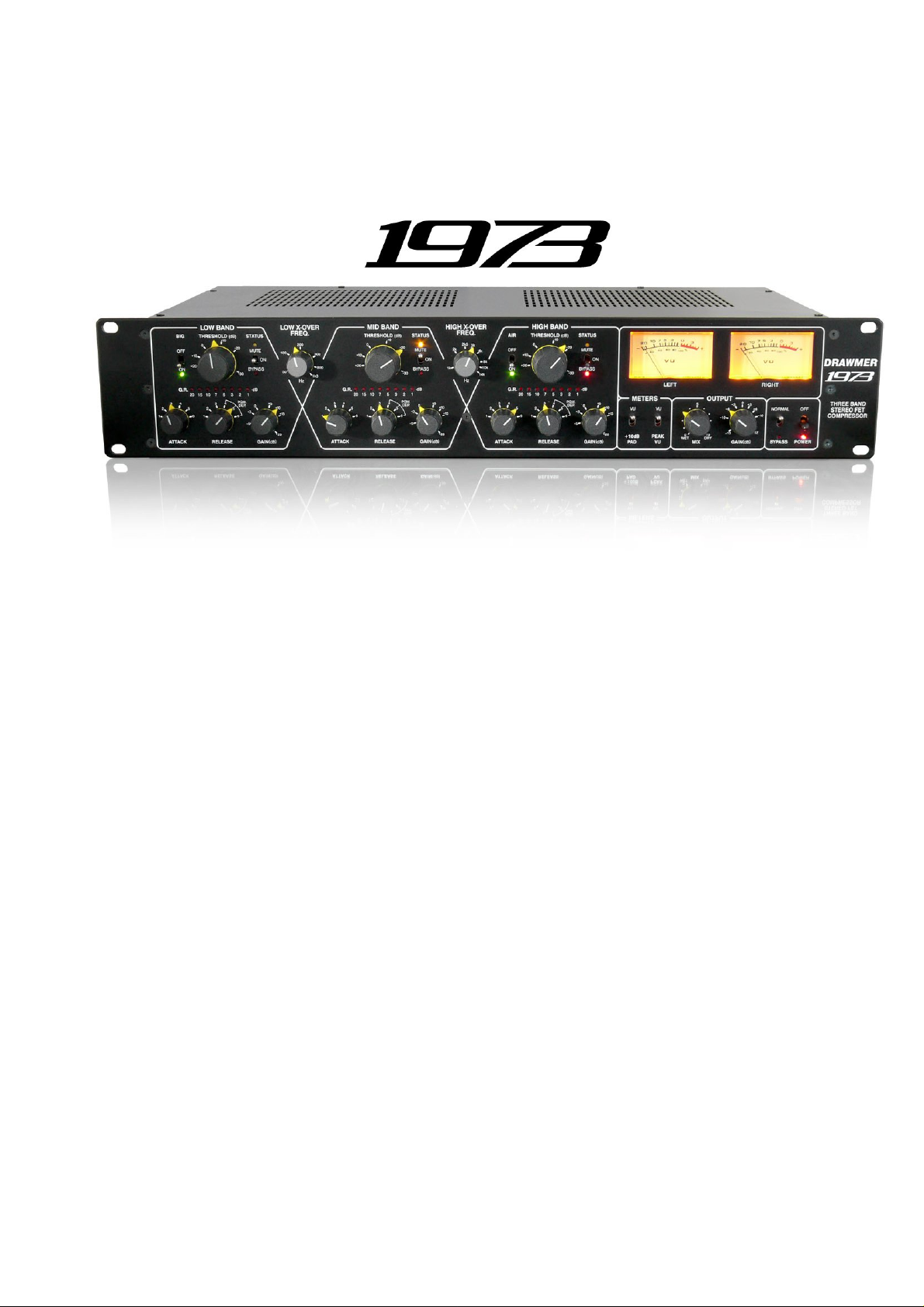
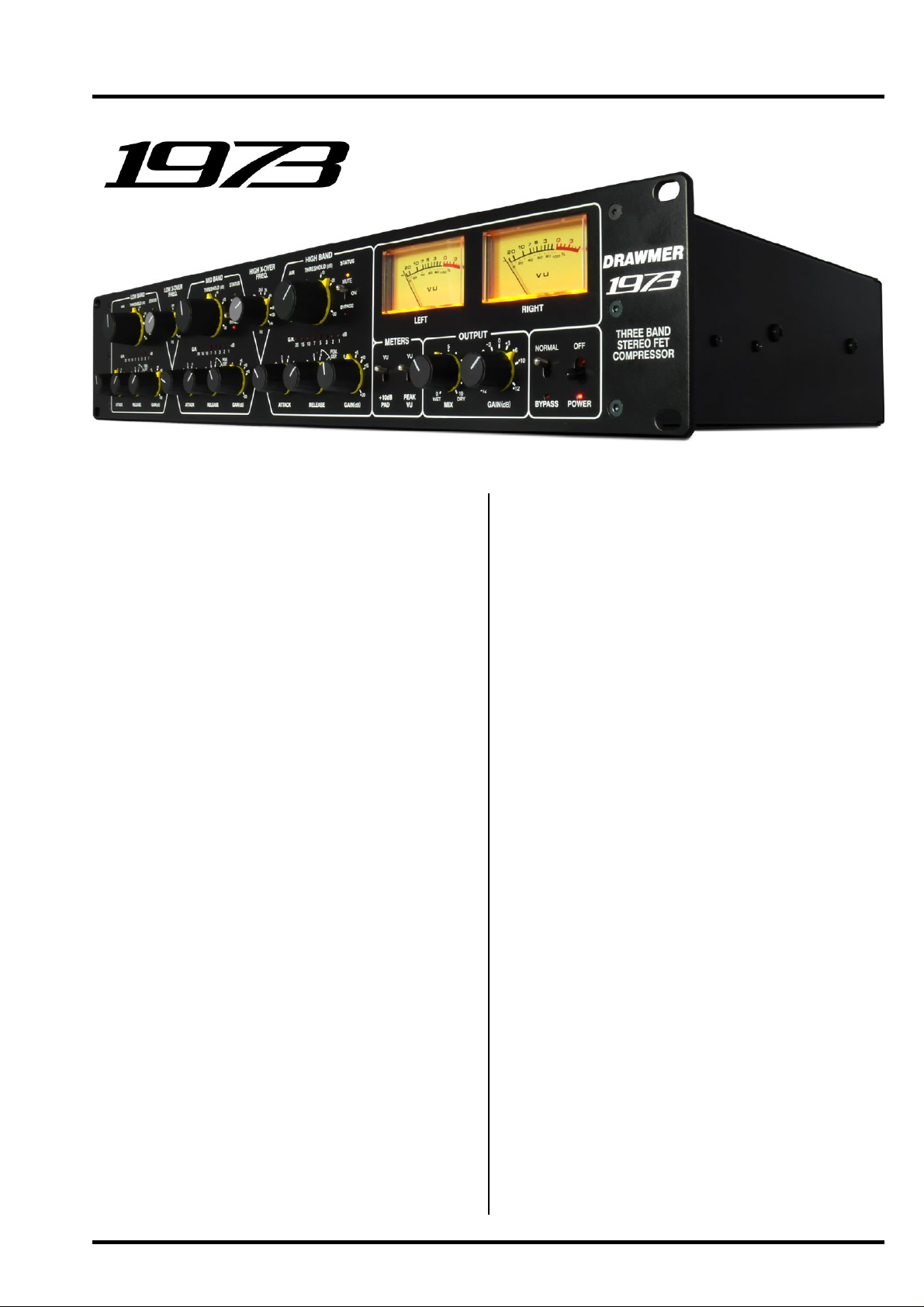
DRAWMER
Three-Band Stereo
FET Compressor
OPERATOR’S MANUAL
Warranty
Safety Con sideration
Chapter 1 - Introduction
Introduction
Installation
Pow er Connec tion
Audio Co nnections
Chapter 2 - Control Descri ption
Control Descripti on
Quick Se tup Proc edure
Chapter 3 - General Information
If a fault develops
Contacting Dr awm er
Sp ecification
Block Diagram
Recall Sheet
. . . . . . . . . . . . . . . . . . . . . . . . . . . . . . . . . . . . . . . . . . . . . . . . . . . . . . . . . . . 2
. . . . . . . . . . . . . . . . . . . . . . . . . . . . . . . . . . . . . . . . . . . . . . . . 2
. . . . . . . . . . . . . . . . . . . . . . . . . . . . . . . . . . . . . . . . . . . . . . . . . . . . . . . 3
. . . . . . . . . . . . . . . . . . . . . . . . . . . . . . . . . . . . . . . . . . . . . . . . . . . . . . . . 4
. . . . . . . . . . . . . . . . . . . . . . . . . . . . . . . . . . . . . . . . . . . . . . . . . 4
. . . . . . . . . . . . . . . . . . . . . . . . . . . . . . . . . . . . . . . . . . . . . . . . . 5
. . . . . . . . . . . . . . . . . . . . . . . . . . . . . . . . . . . . . . . . . . . . . . . . . 6
. . . . . . . . . . . . . . . . . . . . . . . . . . . . . . . . . . . . . . . . . . . . . 9
. . . . . . . . . . . . . . . . . . . . . . . . . . . . . . . . . . . . . . . . . . . . . . . . . 10
. . . . . . . . . . . . . . . . . . . . . . . . . . . . . . . . . . . . . . . . . . . . . . . .10
. . . . . . . . . . . . . . . . . . . . . . . . . . . . . . . . . . . . . . . . . . . . . . . . . . . . .10
. . . . . . . . . . . . . . . . . . . . . . . . . . . . . . . . . . . . . . . . . . . . . . . . . . . 1 1
. . . . . . . . . . . . . . . . . . . . . . . . . . . . . . . . . . . . . . . . . . . . . . . . . . . . . 12
CONTENTS
Page 2
COPYRIG HT
This manual is copy right ed © 2014 by Dr awmer Electronics Ltd. With all right s r eser ved. Under copy r ight
laws, no part of this publi cati on may be repr oduced, tr ansmit ted, s tored in a r etriev al sy stem or tr ansl ated
into any language in any fo rm by any m eans, mechanical , optical , electronic , recor ding, or other wise, wit hout the written permission of Drawmer El ectronics Ltd.
ONE YEAR LIMITED WARRANTY
Drawmer Elect ronics Ltd., warrants the Drawm er 1973
Three-Band Stereo FET Compressor to conform
substantially to the specifications of this manual for a period
of one year from the original date of purchase when used
in accordance with the specif ications detailed i n this
manual. In the case of a valid warranty cl ai m, your sole
and exclusive remedy and Draw mer’s entire liability under
any theory of liability will be to, at Drawmer’s discretion,
repair or replace t he product without charge, or, if not
possible, to refund the purchase price to you. This warranty
is not transferable. It applies o nly to the original purchas er
of the product.
For warranty service please call your local Drawmer dealer.
Alternatively call Drawmer Electronics Ltd. at +44 (0)1709
527574. Then ship the defective product, with transportation
and insurance charges prepaid, to Drawmer Electronics
Ltd., Coleman Street, P arkgate, Rother ham, S62 6EL U K.
Write the RA number in large letters in a prominent position
on the shipping box. Enclose your name, address,
telephone number , copy of the original s ales invoice and a
detailed description of the problem. Drawmer will not accept
responsibility for loss or damage during transit.
SAFETY CONSIDERATIONS
REPLACE TH E MAINS FUSE ONL Y WITH
A FUSE TH AT CONFORMS TO IEC127-2.
250 VOLT WORKING, TI ME D ELA Y TY PE
RA TED A T 230V=T25 0mA and 1 15V=T 500mA.
DRAWMER
1973
Three-Band Stereo
FET Compressor
CAUTI ON - MAINS FUSE
TO REDUCE THE RISK O F FIRE
AND BODY SI ZE OF 20mm x 5mm.
THE M AINS I NPUT FUSE M UST BE
This warranty is void if the product has been damaged by
misuse, modification or unauthorised rep air.
THIS W ARRANTY IS IN LIEU OF ALL W ARRANTIES,
WHETHER ORAL OR WRITTEN, EXPRESSE D, IMPLIED
OR STATUTORY. DRAWMER MAKES NO OTHER
WARRANTY EITHER EXPRESS OR IMPLIED,
INCLUDING, W ITHOUT LIMITATION, ANY IMPLIED
WARRANTIE S OF MERCH ANT ABIL ITY , FITNESS FOR
A PARTICUL AR PUR POSE, OR NON-IN FRINGEMENT.
PURCHASER’S SOLE AND EXCLUSIVE REMEDY
UNDER THIS WARRANTY SHALL BE REPAIR OR
REPLACEMENT AS SPECIFIED HEREIN.
IN NO EVENT WILL DRA WMER ELECTRONICS LTD. BE
LIABLE FOR ANY DIRECT, INDIRECT, SPECIAL,
INCIDENTAL OR CONSEQUENTIAL DAMAGES
RESULTING FROM ANY DEFECT IN THE PRO DUCT,
INCLUDING LOST PROFITS, DAMAGE TO PROPERTY ,
AND, T O THE EX TENT P ERMITTED BY LA W, DAMA GE
FOR PERSONAL INJURY, EVEN IF DRAW MER HAS
BEEN ADVISED OF THE POSSIBILITY OF SUCH
DAMAG ES.
Some states and specific c ountries do not al low the
exclusion of implied warranties or limitations on how long
an implied warranty may last, so the above limitations may
not apply to you. Thi s warranty giv es you specif i c l egal
rights. Y ou may have additional rights that vary from state
to state, and country to country.
CAUTION - MAINS CABLE
DO NOT A TTEMPT T O CHANGE
OR T AMPER WITH THE
SUPPLIED MAINS CABLE.
CAUTION - SERVICING
DO NOT PERFORM ANY SERVICING.
REFER ALL SERVIC ING TO QUALI FI ED
SERVICE P ERSONNEL.
WARNING
TO REDUCE THE RISK OF FIRE OR
ELECTRIC SHOCK DO NOT EXPOSE
THIS EQUIPMENT TO RAIN OR MOISTURE.
In the interests of product deve lopment, Drawmer reser ve the right to modify or
improve specifications of this product at any time, without prior notice.
2
DRAWMER 1973 OPERATOR’S MANUAL
Page 3
DRAWMER
THREE-BAND STEREO
FET COMPRESSOR
CHAPTER 1
INTRO DUCTI ON
The 1973 is a Three Band Compress or with the versatility,
control and ability to shape sound that no full band
compressor could ever provide and at an affordable price.
Expanding on the renowned range of dynamics processors
DRAWMER introduce an affordable Three Band Stereo
FET Compressor that every engineer wi ll com pletely
appreci ate - t he 1973. T he c ulm inat ion of 30 y ears of
dev elopment and experience, the 1973 combi nes the
functionality and control of the world cl ass DRAWMER
S3 with the familiarity and quality of the illustrious 1960
and 1968, providing three bands of transparent, intuitive
compression for the price of a conventional single full band
compressor .
How does the 1973 differ from a full band compressor? In
essence, the 1973 comp rises a set of crossov er f ilt ers
that spl it s the audi o signal i nto t hree f requency bands,
each split signal then passes through its own compressor
and is independently adjusted, after which the signals are
recombined and the final Wet/Dry mix and levels can be
adjusted. The advantage is that one band's compression
has no affect on the others.
What's so good about a three band compressor anyway?
The 1973 can pul l of f am azing feat s t hat a single-b and
compressor could never accomplish. For example, it can
easily pr ev ent an acousti c gui tar, cell o, or doub le b ass
from sounding boomy on low notes without thinning the
highs.
Are you recor ding a v ocal tr ack that sounds too shril l?
The timbre can easily be altered without eliminating detail
and clarity. Adding heavier compression in the bass band
can add to the thickness and richness of the voice, in the
mid band raspiness is controlled, whilst compression to
the high band can give sizzle and definition to an otherwise
bland voi ce. In addition, sibilance can easil y be tamed.
In a mastering situation, having independent control over
each band can resolve a problem mix, pulling out individual
instruments, brighte n the brilliance/air or make the bottom
end of a mix sou nd huge wh ilst sim ultaneously av oid
"pumping" or "breathing" artifacts and increase headroom.
Multiband compressors can be intimidating and difficult
to use due to a minefield of controls and poor lay out, with
this in mind, the 1973 has been designed to be as s imple,
familiar and intuitive as possible whilst still giving complete
control over the audio.
Main Features:
Standard int uiti v e co ntrol s such as Thr eshold , G ain,
Switched Attack & Release with Gain Reducti on
Metering on Each Band.
Fast Reacting Soft Knee F.E.T . Design with excellent
Left/Right Tracking across the Full Range of
compression.
Variable Wet/Dry Mix plus Output Gain Knobs give a
'Paral lel Co mpression ' fun ction wit hout t he need for
external mixing devices, prov iding Complete and
Effortless Control over the amount of compression used
and Output Le vels.
Variable Band Split Filters at a 6dB Per Octave slope
with Switch-able Mute and Bypass on Each Band make
'Tuning In' to a Frequency Simple.
‘Big’ and 'Air' Modes Help to preserve the Very Deep
Lows and Enhance the Sparkling Highs.
Two Analogue V .U. Meters with Switchable +10dB Meter
Rescale Modes and a Switchable ‘Peak’ mode to
Display Fast Transients Not Normally Seen on
Conventional V.U.s.
Internal Low Hum Toroidal Linear Power Supply with
Voltage Selector Switch
Classic Drawmer Build Quality with Rugged Steel
Chassis and Aluminium Front Panel.
DRAWMER 1973 OPERATOR’S MANUAL
3
Page 4
INST A LLATION
The 1961 is designed for standard 19" rack mounting and occupies 2U of rack space. Fibre or plastic
washers may be used to prevent the front panel becoming marked by the mounting bolts.
- Car e should b e taken in the choic e of posit ioni ng. The un it shoul d not be mo unted whe re other
equipment obstructs the normal air flow . The unit should not be situated near any heat source, such
as a radiator , stove or a high power amplifier that would generate heat.
- The appliance should not be operated near any water or in a location where moisture might be
present.
- Always connect the mains earth to the unit.
If the 1973 i s to be conti nuousl y move d from one l ocation to another , w e suggest u sing add itio nal suppor t in
the rack at the rear of the unit.
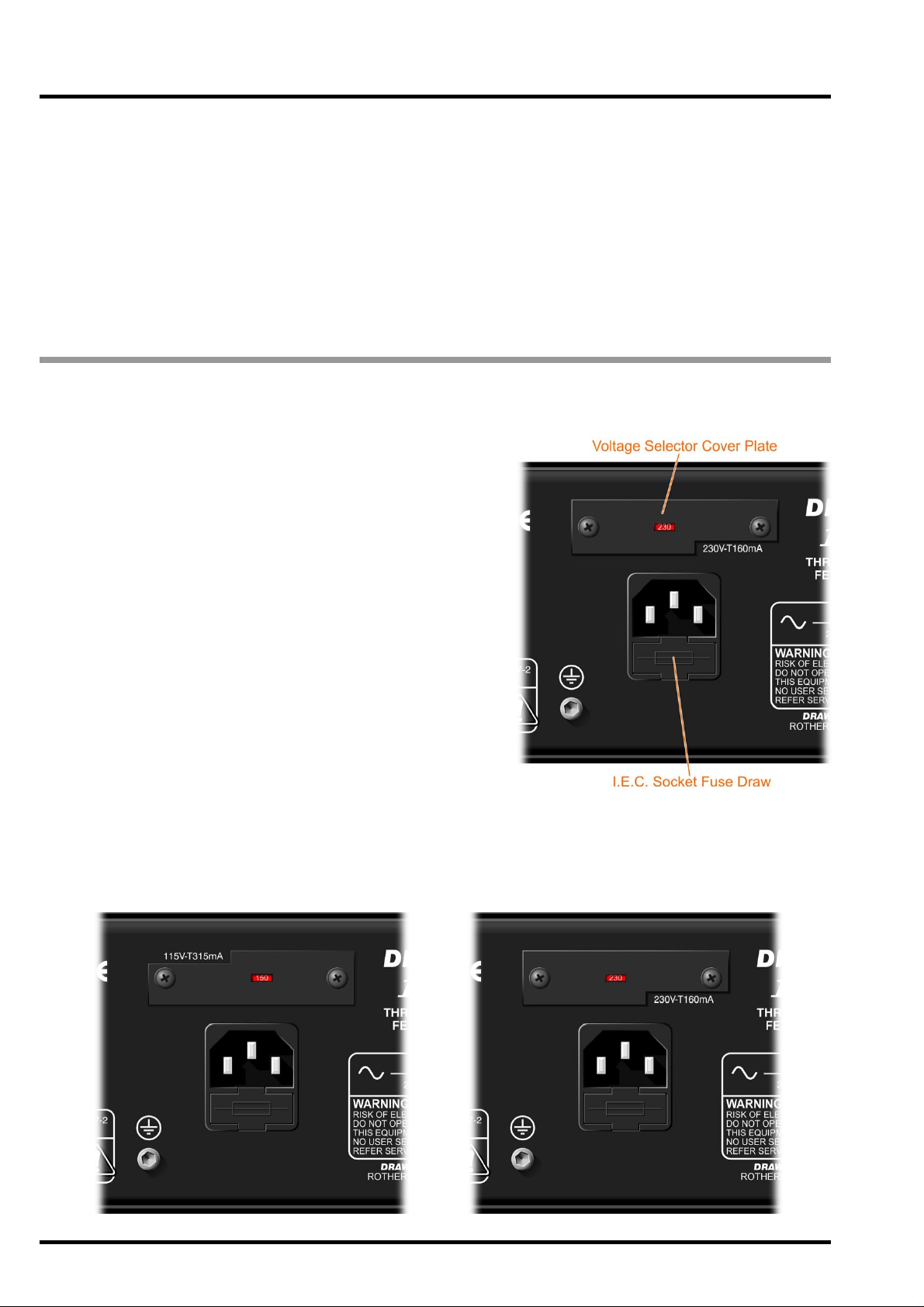
POWER CONNECTION
The unit wi ll have been supplied with a power cable suitable
for dom esti c p ower ou tlet s in yo ur c ountr y . F or your own safety
it is im portant that y ou use thi s cable. The unit shoul d alway s
be connected to the mains supply earth using thi s cable, and
no other.
If for some reason the unit is to be used at a mains input
operating voltage which is different to that as supplied, the
following pr ocedure must be carried out.
1: Disconnect the unit from the mai ns.
2: Remove the tw o screws holding the voltage sel ection
cover -p lat e.
3: Remove the cover plate and slide t he swit ch fully to i ts
opposi te end.
4: Rotate the cover pl ate one half turn ( 180 degrees) and
refit the two screws.
5: Replace wi th a cor rectl y rated fuse for the sel ected
operation vol tage in the IEC s ocket:
230V-T250mA and 115V -T500mA
6: Re-connec t to mains power source.
Never disconnect the earth
from the mains supply
4
DRAWMER 1973 OPERATOR’S MANUAL
Page 5

AUDIO CONNECTIONS
A typic al setup for connecting the 1973 would be by the use of a Y-lead between the two input and output
xlr’s on the r ear of the 1973 and inser t point for the respec tive channel of the desk - this would be repeated
for both channels. The wiring of the Y-lead can be seen below .
The inputs and outputs are electronic ally balanced on conventionally wired XLR s (pin 1 screen, pi n 2 hot,
pin 3 cold and XLR shell is connected to chassi s). Th e operating lev el is nominal ly +4dBu. Balanced use is
recommended.
• Ground Loops:
If ground loop problems are encountered, never disconnect
the mains earth, but instead, try disconnecting the signal screen
on one end of each of t he cables c onnecting th e outputs of the
1973 to the patchbay. If such measures are necessary,
balanced operation is recommended.
• Inter feren ce:
If the 1973 is to be used where it maybe exposed to
high levels of disturbance suc h as found close to a TV
or radio transmitter, we advise that it is operated in a
balanced configuration. The screens of the signal cables
should be connected to the chassis connection on the
XLR connector as opposed to connecting to pin1.
The 1973 conforms to the EMC standards .
DRAWMER 1973 OPERATOR’S MANUAL
5
Page 6

CHAPTER 2
CONTROL DESCRIPTION
The 1973 s hare s similar parameters to a st andard full band co mpress or , such a s the Draw mer 1968, th e difference being
that the stereo signal is split into low, mid and high bands, each one processed separately without affecting the other,
and then summed back into a stereo signal again before output.
As you would imagine a multiband compressor
could become a very intimidating beast due to
the number of controls, however, the 1973 as been
layed out to be as i ntuiti v e to use as possible.
Anyone familiar with the Drawmer 1960’s rang e,
the S2 and especially the S3 compressors should
be immediately at home.
Essentially the 1973 comprises the three low , mid
and high compressor band s to the left of the unit
with the crossover frequency knobs inbetween.
These bands are all al most identi cal, the onl y
difference being the Big and Air switches. T o the
right of the unit the meters and output sections
are located (see be low diagram).
X-OVER FREQUENCIES
The 6dB per octave crossov er frequencies
determine the points within the frequency
spectrum one band stops t o process aud io, and
another band takes over.
Low X-Over Frequency: 50Hz - 1.3kHz
1
Sets the frequency point at which the split
between low and mid bands occurs.
High X-Over Frequency: 1kHz - 14kHz
2
Sets the frequency point at which the split
between mid and high bands occurs.
6
DRAWMER 1973 OPERATOR’S MANUAL
The three bands are almost identical - the only difference being the
inclusion of ‘Big’ (8) and ‘Air’ (9) on the low and high bands respectively.
Page 7

The following diagram provides a good, but general, idea of some useful frequencies that will aid in setting the
crossover frequencies:
LOW BAND, MID BAND, HIGH BAND
Threshold: infinity - -32dB all bands
3
Determi nes the level bel ow which com pression start s to take
place. The 1973 incor porates a So ft Knee, more compression is
applied automatically as the input signal level increases, negating
the need for a Ratio control.
Attack: see below diagram all bands
4
Controls the s peed that the c ompresso r respon ds to signa ls that
exceed the level set by threshold. Six switchable Attack settings.
All times are nominal, the actual attack time is further modified
by the release setting chosen.
Release: see below diagram all bands
5
Sets the time taken for the signal to return to normal after the input level has fallen below threshold.
The first three switch positions ar e fixed and provide progress ively increasing releas e times, while positions F(ast),
M(id) and S(low) cause the release times to vary in a manner which automatically adapts to the dynamics of the
incoming signal.
Release Presets
Attack Presets
Gain: -10 - +20dB all bands
6
During compression the signal is attenuated, gain may be required to produce the required output level. In addition,
as the 1973 is multi-band, the three gain controls are used to adjust the levels of each band to obtain a desirable
overall signal, or to bring out the bass, treble etc.
7
Gain Reduction Meter: -1,-2,-3,- 5,-7, -10,-15,- 20dB all bands
Use the meter as a guide to how much gain to re-apply using the Gain control .
DRAWMER 1973 OPERATOR’S MANUAL
6
7
Page 8

8
Big: Off - On low band only
Big is located only on the low band and when on reduces the side-chain's sensitivity to low frequencies, with the
result that less gain reduction is applied, creating the effect that the bass is louder or 'bigger'. The 'BIG' mode
enables application in buss compression situations where you still want thick and warm tone yet complete dynamics
control.
9
Air: Off - On high ba nd only
Air is located only on the high band and is used to re-introduce high frequencies, which can sometimes be lost
after heavy compression so that it sounds more intimate, detailed and transparent, but without making it sound
harsh or introducing any noticeably unnatural artifacts. Cymbals are more vibrant without becoming splashy, and
vocals sound more open but without becoming sibilant.
10
Status: Mute/On/Bypass all bands
A three pos tion Status s witch is located in each of the bands that allows normal operation, bypas s or muting of that
band. In the ON p osition all the controls of that pa rticular band are in o peration and co mpression ta kes place. In the
“BYP ASS” position the s ignal for the low , mid, or high band is allowed t o pas s through t o the summing st age witho ut
being altered by the comp ressor s tage (including gain). In the “MUTE” position the signal for that particular band is
effectively turned off - any combination of mute is available, to hear only the signal of the low band mute the mid and
high bands etc.
Using a combination of mute and bypass switches for the various bands allows the operator to hear and monitor
only the frequencies that are required and so ‘tune in’ to the low, mid and high frequency settings using the crossover controls.
METERS
11
VU Meter:
Two backlit m oving coil V U meters
monitor the level of the output signal.
Note: T o see the input level on the VU
meters the By pass switch should be
on.
12
Pad: Vu - +10dB
A two position switch adjusts the meters
to show either normal output level, (and
for those working at ‘hot’ output levels)
VU +10dB i. e. with the switch at VU
+10dB, when the VU meter reads 0dB
the actual level is +10dB.
13
Peak VU: Peak VU - VU
On smooth, gentle pieces of music the “VU” (average level) setting would be sufficient, however, on fast dynamic
signals the “Peak VU” setting provides more accurate readings.
OUTPUT
14
Mix: WET - DRY
A variable control that mixes a user defined amount of 'uncompressed' signal (dry) with the compressed signal
(wet) to create a 'parallel compression effect' without the need for external mixing devices. In this way the amount
of overa ll co m pres sion on t he stereo si gna l i s under c om pl ete cont rol - set t he t hree band s to prov ide heavy
compression but then reduce the overal effect by mixing in some of the dry signal using the mix control.
15
Gain: -12 - +12dB
The 1973 provides a single control to modify the stereo output level after summing, without having to adjust the three
band gain c ontrols (and thus altering the mix). Adjus t so that the outpu t signal approa ches the des ired level only on
signal peaks.
16
Bypass: Off - On
A fully balanced hard-wire unit bypass connects the input directly to the output without alteration.
Note: To se e the input level on the VU meters the Byp ass sw itch should be o n, as the meters display the level found
at the output.
17
Power: Off - On
Turns the 1973 on and off. This switch is hard wired and so when off the 1973 will draw no power
8
DRAWMER 1973 OPERATOR’S MANUAL
Page 9

QUICK SETUP P ROCEDURE
Please note that the following procedure is only a guide. All audio is different, requiring numerous settings, however,
this should give a good staring point:
1 ) Set the compressor settings to be the same on all bands - Threshold fully counter-clockwise, Gain at 0dB,
the Attack in a mid position (2 or 3) and Release set to F(ast). The overall Gain control should be set to 0dB,
and the Mix at 0 (Wet).
2 ) Turn on the Bypass switch (bottom right) so that the input signal is heard without compression and adjust the
incoming signal until the VU meters rear 0dB. Set the Bypass switch back to Normal.
3) With the Low X-Over Frequency set fully counter-clockwise, and the High X-Over Frequency set fully clockwise,
listen to the audio and bring in the two knobs to the positions that you think the cross-over points should be set
- generally to separate the main bass and treble sounds from the mid-range. Using a combination of Mute and
Bypass sw itches for the various bands allows the operator to monitor only the frequencies that are required and so
tune the low, mid and high frequencies.
4 ) Keeping an eye on the Ga in Reduc tion Me ters alter the Threshold level control for each band until the desired
compression level is achieved - a G .R. level up to -10dB is acceptable.
5 ) Adjust the Gain control of each band until 0dB is reached on the Output VU meter. T o see only the band that
is being adjusted on the VU meter Mute the other two bands.
6 ) Set the Attack and Release settings of each band to suit the audio being compressed.
7) The Threshold and Gain of each band can be modified to achieve the desired compression, levels and tonal
balance to the overall signal.
8 ) At this point the Bypass sw itch can be toggled to listen to the affect that the 1973 is having on the audio.
Adjust to suit.
9 ) Once each band is setup correctly modify the overall Output Gain and Mix until the VU meters read 0dB
(more if in +10dB VU mode) and the desired amount of compression is heard.
Below is an example setup that could be used for a General Pop Mix, though, of course, as all music is diverse and
varied, will not be ideal elsewhere.
DRAWMER 1973 OPERATOR’S MANUAL
9
Page 10

GENERAL INFORMATION
CHAPTER 3
IF A FAULT DEVELOPS
For warranty servic e p lease call Drawmer Electronics Ltd. or
their nearest authorised service facility, giving full details of
the difficulty.
A list of all main dealers can be found on the Drawmer
web pages .
On receipt of this information, service or shipping instructions
will be forwarded to you.
No equipment should be returned under the warranty without
prior consent from Drawmer or their authorised representative.
For service claims under the warranty agreement a service
Returns Authorisation (RA) number will be issued.
Write this RA number in large letters in a prominent position
on the shipping box. Enclose your name, address, telephone
number, copy of the original sales invoice and a detailed
description of the pro blem.
Authorised returns should be prepaid and must be insured.
All Drawmer products are packaged in specially designed
contai ne r s for protection. If the unit is to be r e t ur ne d, t he origina l
container must be used. If this container is not available, then
the equipment should be packaged in substantial shock-proof
material, capable of withstanding the han dling for the transit.
CONTACTING DRAWMER
Drawmer Electronics Ltd., will be pleased to answer all
application questions to enhance your usage of this
equipment. Please address correspondence to:
Drawmer (Tec hnical Help line)
Coleman Street
Parkgate
Rotherham
S62 6EL
UK
Alternatively contact us by E-mail on :
for sales enquiries: sales@draw mer.c om
or for technical issu es: tech @drawmer.com
Further information on all Drawmer dealers, Authorised service
departments and other contact information can be o btained
from our web pages on:
http://www.drawmer.com
1973 THREE-BAND STEREO FET COMPRESSOR
DATA SPECIFICATION
INPUT
Input Impedance 20k Ohms or greater
Maximum Input Level +26dBu
OUT PUT
Output Impedance 100 Ohm s
Maximum O utput L evel +25dBu into 10k Ohms Load
FREQUENCY RESPONSE
<5Hz to 51kHz -1dB
<3Hz to 70kHz -3dB
CROSSTALK < -80dB @ 1kHz
NOISE AT UNITY GAIN
with flat EQ response switched in circuit
Wideband 22Hz - 22kHz
AV -82dB -87dB
% DIST ORTION (THD & NOISE) @ 1kHz
0dB (ref +4) 0.03%
10dB (ref +4) 0.07%
20dB (ref +4) 0.5%
POWER REQUIREMENTS
230Volt or 115V a t 50-60hZ, 60VA
FUSE RATING
T250mA for 230Volt,
T500mA for 115Volt
Conforming to IEC 127-2
FUSE TYPE
20mm x 5mm, Class 3 Timed-Blo, 250Volt working
CA SE SIZE
482mm (W) x 88mm (H) x 270mm (D)
WEIG HT 4.2Kgs
10
DRAWMER 1973 OPERATOR’S MANUAL
Page 11

BLOCK DIA GRAM
DRAWMER 1973 OPERATOR’S MANUAL
1973 ver 01 B 20/03/14
11
Page 12

12
DRAWMER 1973 OPERATOR’S MANUAL
 Loading...