


The DrawingBoard VI |
1 |
|
|
DrawingBoard VITM
User’s Guide
The DrawingBoard VI family of small format and large format digitizers

2 |
The DrawingBoard VI |
|
|
We at GTCO CalComp are proud of our digitizer products. We strive to bring you the best the technology has to offer. We urge you to visit our Web site, where we will post the latest information regarding updates and changes that may impact the information in this User’s Guide.
Navigate to:
www.gtcocalcomp.com

The DrawingBoard VI |
Table of Contents |
3 |
Table of Contents
What is DrawingBoard VI? |
5 |
Parts Checklist |
6 |
What You Will Need to Use DrawingBoard VI |
7 |
PC Requirements |
7 |
For a USB Installation |
7 |
For an Optional Serial Installation |
7 |
DrawingBoard VI Overview |
8 |
Active Area |
8 |
Menu Strip |
8 |
Indicator Light |
8 |
Transducer |
8 |
Setting Up Your DrawingBoard VI |
10 |
Preparing the Large Format DrawingBoard VI |
10 |
Mounting on the Stand |
10 |
Attaching the Optional Accessory Tray or Plan Holder |
10 |
Software Configuration |
11 |
Configuring Non-Wintab Applications |
11 |
Installing the TabletWorks Driver |
11 |
Hardware Configuration |
11 |
USB Connection |
12 |
Optional RS232 Serial Connection |
13 |
Tablet Power-On |
13 |
Customizing the Tablet |
14 |
Overview of the Menu Strip |
14 |
Selecting a Pre-Programmed Setup |
15 |
Selecting a Custom Setup |
16 |
Tablet Options |
17 |
Recommended Setups for Common PC Software Applications |
21 |
Restoring a Pre-Programmed Setup |
24 |

4 |
Table of Contents |
The DrawingBoard VI |
Learning the Basics |
25 |
Using the Transducer |
25 |
Using the Cursor |
25 |
Using the Pen |
26 |
Learning Basic Movements |
27 |
Clicking and Double-Clicking |
27 |
Dragging |
27 |
Caring for the Tablet and Transducer |
28 |
Cleaning the Tablet |
28 |
Cleaning the Cursor |
28 |
Replacing the Pen Tip |
28 |
Replacing the Cordless Pen Batteries |
29 |
Replacing the Cordless Cursor Batteries |
30 |
Troubleshooting |
31 |
Reducing Monitor Interference |
31 |
Changing the Frequency of the Cordless Cursor |
31 |
Changing the Frequency of the Cordless Pen |
32 |
Changing the Frequency of a Corded Transducer |
32 |
Tablet Checklist |
32 |
Computer Checklist |
33 |
Software Checklist |
33 |
Does the tablet work with some software? |
33 |
Did the software work in the past? |
34 |
Troubleshooting Chart |
35 |
Returning your Tablet for Repair |
36 |
Repackaging for Shipment |
36 |
Parts and Accessories |
37 |
Glossary |
38 |
Regulatory Statements and Warranty |
42 |
Radio and Television Interference |
42 |
Canada |
42 |
Declaration of Conformity |
43 |
European Union Emission Directive |
44 |
European Union WEEE Directive |
44 |
Japan |
45 |
Bescheinigung des Herstellers/Importeurs |
45 |
Limited Warranty for the DrawingBoard VI |
46 |

The DrawingBoard VI |
Introduction |
5 |
What is the DrawingBoard VI?
The DrawingBoard VI belongs to a class of computer input devices called graphic tablets, or digitizers. A digitizer is an electronic tablet work surface. The position of a transducer, a handheld cursor or stylus pen, on the work surface of the DrawingBoard VI is converted—digitized—into data for computer processing. Data output from the DrawingBoard VI digitizer is in the form of an X/Y coordinate pair that pinpoints the precise location of the transducer on the tablet surface. By placing a drawing or sketch on the tablet’s surface and tracing over it, graphical information can be easily converted into accurate digital information for entry into the computer. DrawingBoard VI digitizers utilize the same Advanced Function Technology that has been setting the world standard for performance since 1975. These high performance tools are engineered with a state-of- the-art positioning grid to ensure reliability, performance and quality. Multiple accuracy versions are available to meet specific system requirements.
The DrawingBoard VI family of small and large format digitizers boasts the highest resolution, 12,700 lines per inch, on the market today, unparalleled accuracy, and a wide range of sizes, providing the perfect solution when the work demands precision data input, particularly over a large surface area. CAD, GIS, engineering, textile, and apparel designers appreciate the variety of cordless and corded cursors and stylus pens available to use with the DrawingBoard VI. An integrated mounting channel on the large format tablet frame allows accessories, such as an accessory tray, to be quickly and easily mounted. Easy-to-use software and programmable function keys round out the picture of a powerful, versatile tool that can be configured to meet the needs of any application environment from drawing, animation, presentation graphics and desktop publishing to drafting and mapping. The high-productivity DrawingBoard VI can be used as both a digitizer and a mouse, eliminating the need for multiple devices at your computer.
In order to send data from your DrawingBoard VI to your digitizing application, your DrawingBoard VI must be physically connected to your computer, and it must be able to transmit that data in such a way that the digitizing application recognizes and understands it. Before you set up your DrawingBoard VI, you should determine:
The requirements of the digitizing software application you are using
Whether your digitizing application requires software drivers to communicate with the DrawingBoard VI
The hardware communications connection (USB or serial) you will be using between the DrawingBoard VI and the computer

6 |
Parts Checklist |
The DrawingBoard VI |
Parts Checklist
DrawingBoard VI digitizing tablet
Transducer (corded or cordless pen, 4-button cursor, or 16-button cursor)
USB Cable
Universal Mounting Brackets
A CD (TabletWorks drivers, documentation, or third party software drivers)
DrawingBoard VI User’s Guide (on the CD)
DrawingBoard VI Quick Start
Registration Card
Optional Equipment
RS232 cable with 9-pin connector for serial connection
Power supply – required only for a serial installation
Accessory Tray (large format only)
Plan Holder (large format only)
Table Feet (large format only)
Manual Lift/Manual Tilt Pedestal (large format only)

The DrawingBoard VI |
PC Requirements |
7 |
What You Will Need to Use DrawingBoard VI
This version of the DrawingBoard is equipped with both a USB interface and an RS-232 serial interface, which requires an optional RS232 cable and power supply. It is compatible with most industry-standard PCs. The TabletWorks CD contains drivers provided by GTCO CalComp and is the only software described in this manual. TabletWorks supports reduced functionality Wintab and TabCon-compatible applications. If you are not sure which drivers are required consult with your application vendor.
A USB connection requires the use of a TabletWorks driver, while a serial connection requires the use of a TabletWorks driver and/or a custom application program. After installing the TabletWorks software, the DrawingBoard VI will work with all Windows-based applications as a mouse, in addition to working as a digitizer with Windows-based applications that are specifically designed for use with digitizers.
PC Requirements
For a USB Installation
Microsoft Windows 98se, Me, 2000, XP, or Vista
One available USB port
10 MB of free disk space
Application software that accepts digitizer input via the Wintab API or TabCon API
For an Optional Serial Installation
Microsoft Windows 98, Me, NT 4.0, 2000, XP, or Vista
One available RS232C serial communication port (Serial signal levels must conform to EIA RS232C specifications.)
10 MB of free disk space
Application software that directly accepts digitizer input via the computer’s RS232C serial port, or via the Wintab API or TabCon API
8 |
Overview |
The DrawingBoard VI |
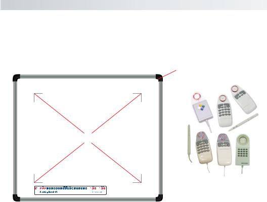
DrawingBoard VI Overview
The DrawingBoard VI digitizer (large format shown here) consists of:
Indicator Light
Active Area
Transducers
 Menu Strip
Active Area
The drawing area—the Active Area—is that portion of the tablet surface designated for digitizing. Its boundaries are marked at each corner by a right-angle crop mark on large format tablets. On small format tablets, the Active Area is delineated by the overlay – not including the menu.
Menu Strip
The Menu Strip is the row of keys located in the lower left corner of the large format tablet and across the top of the small format tablet. You can use the keys to customize your tablet, or to assign macros to Configuration keys for greater productivity.
Indicator Light
The power/proximity LED in the upper right corner of the large format DrawingBoard VI frame or the Prox/Config light above the Menu Strip on the small format tablet is the Indicator light. It remains off when the power is On. However, when the transducer is in prox (within the range) of the Active Area, the LED is solid green.
Transducer
Two types of transducers can be used with DrawingBoard VI: pens and cursors. Both are available in corded and cordless versions. The corded transducers get their power from the digitizer. Cordless transducers are powered by batteries. They will go into a battery-saving Sleep Mode when

The DrawingBoard VI |
9 |
no button has been pressed for one to five minutes, depending on the type of transducer you are using. To reactivate a sleeping transducer, press one of its buttons.
Cursors
The cursor is similar in appearance to a mouse, except that it has an attached lens with crosshairs for highly accurate detail work. Cursors are available in 4- or 16-button models. In addition, there is a special 16button cursor available with high-accuracy tablets. This cord-only style cursor has a lens area that can be illuminated.
Pens
Each pen is similar in appearance to a ballpoint pen. The pen transducer has three buttons, two on the side of the barrel and one in the pen tip. Three different types of pens are identified by a colored ring on the pen barrel—the Click Tip has a light blue ring; the Pressure Tip, a black ring; and the Lite Touch Tip, a red ring.
10 |
Installation |
The DrawingBoard VI |
Setting Up Your DrawingBoard VI
The instructions below describe how to set up your DrawingBoard VI. Before you begin, please take a moment to fill out and mail the Warranty Registration Card.
Preparing the Large Format DrawingBoard VI
Mounting on the Stand
You can place your DrawingBoard VI on a table, desk, or drafting table. Or, you can mount your DrawingBoard VI on a stand or a pedestal. The tablet’s Universal Mounting Brackets attach directly to those stands that have tilt arms. (The old style stands with tilt pads require right-angle mounting brackets, which are attached to the tilt pads. The tablet’s Universal Mounting Brackets are then attached to the right-angle mounting brackets.)
Center the tablet over the attached Universal Mounting Brackets and screw the Thumbscrews into the T-Nuts in the mounting channel in the tablet’s frame.
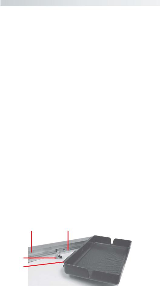
Attaching the Optional Accessory Tray or the Optional Plan Holder
Additional T-Nuts have been included in the perimeter mounting channels on the DrawingBoard VI frame. You can position the Plan Holder or Accessory Tray (see Parts and Accessories) where it is most convenient for you by attaching it to any one of the available T-Nuts. The following instructions and the graphic below detail the installation of the Accessory Tray.
Simply slide the Tray Rails into the channel and line up the hole in the tray with the hole in the T-Nut. Tighten the Thumb Screw to secure the Accessory Tray.
DrawingBoard VI |
|
Frame |
T-Nut |
Thumb
Screw
Tray |
|
|
|
Accessory |
|
||||
|
|
|
||
Rails |
|
|
|
Tray |
The DrawingBoard VI |
Installation |
11 |
Software Configuration
Software drivers provide the communication bridge between your digitizing software application and your DrawingBoard VI. You should install only the drivers necessary for the DrawingBoard VI to work with your application software. If you are not sure which drivers are required, consult with your application vendor.
Configuring Non-Wintab Applications For Optional Serial Interface Only
Many application programs provide configuration information for specific digitizers. If the DrawingBoard VI digitizer is not listed, you can use the configuration for GTCO Digi-Pad Type 5 or Type 5A (T5/T5A), CalComp 9100/9500, or Summagraphics Microgrid III or ID Series.
Installing the TabletWorks Driver
Insert the CD into the CD-ROM drive on your computer. The installer will autoload. If it doesn’t, click on the Start button on the Windows Task Bar and select Run from the menu. Type X:\setup.exe (X represents the CD drive letter). Follow the onscreen prompts to complete the installation.
A TabletWorks icon  will display in the System Tray on the Windows Task Bar. Right-click on the icon to display the TabletWorks Menu, which provides access to all the TabletWorks features.
Hardware Configuration
When you use the USB interface, no data output configuration is required. When you use the optional serial interface, The DrawingBoard VI must be configured to send data in a format that is compatible with the application software. Different applications have different requirements when interacting with a digitizer. Determine, if you haven’t already, which communication connection you will be using—USB or serial.

12 |
Installation |
The DrawingBoard VI |
1Connect the corded transducer – cursor or pen – to the appropriate jack on the digitizer’s Connector Panel. The connector is keyed and will fit only the correct jack. Do not force it.
Transducer |
USB |
Power |
Serial |
Power Switch |
(POINTER) |
(USB) |
(9V DC) |
(RS232) |
(I/O) |
Controller
Box
DrawingBoard VI Connector Panel (large format shown here)
USB Connection
The DrawingBoard VI USB port connection is USB 1.1 and 2.0 compatible. When the digitizer is connected to the USB port, Windows will recognize that there is a new device connected. If Windows displays the Found New Hardware prompt, follow the onscreen instructions to complete the driver installation.
1Connect the interface cable to the USB jack on the DrawingBoard VI Connector Panel. The connector is keyed and will fit only the correct jack. Do not force it.
2Connect the other end of the USB cable to any one of the USB ports

 on your computer or USB hub. Turn the Power Switch on. The digitizer will beep once, indicating it
has power.
DrawingBoard VI USB Connection |
|
Transducer |
Computer |
|
|
(POINTER) |
|
USB (USB)
Power is supplied through the USB port. No additional power source is needed for a USB installation, even when you are using the DrawingBoard VI with a corded high-accuracy cursor.

The DrawingBoard VI |
Installation |
13 |
Optional RS232 Serial Connection
1Connect the RS232 serial cable to the serial jack on the Connector Panel. The connector is keyed and will fit only the correct jack. Do not force it. Connect the other end to an RS232 serial port on your computer.
2Plug the power supply into an AC outlet. Connect the power supply to the appropriate jack on the Connector Panel. Turn the Power Switch on. The digitizer will beep once, indicating it has power.
DrawingBoard VI Serial Connection
Transducer |
Computer |
|
|
(POINTER) |
|
Power |
Serial |
(9V DC) |
(RS232) |
Tablet Power-On
The DrawingBoard VI power switch is located at the rear of the tablet on the Controller Connector Panel. When turned On, the DrawingBoard VI’s Indicator light will begin blinking.
If you are using a cordless transducer, turn it on by pressing any button on the tool. The Indicator light will glow steadily when the transducer is inside the Active Area of the tablet. When the transducer moves outside the Active Area, the Indicator light will go off.
14 |
Tablet Customization |
The DrawingBoard VI |
Customizing the Tablet
You can customize your DrawingBoard VI digitizer and transducer to suit your individual work requirements using TabletWorks. TabletWorks is a Windows program included with the Digitizer Software that helps you use the full capabilities of your DrawingBoard VI. You can map your digitizer to the screen area and program stylus and cursor buttons with custom macros. To learn how to use TabletWorks, please refer to TabletWorks Help on the CD.
If you have chosen to use the optional serial interface, you will be able to customize the tablet data format and communications parameters using the Menu Strip, described below.
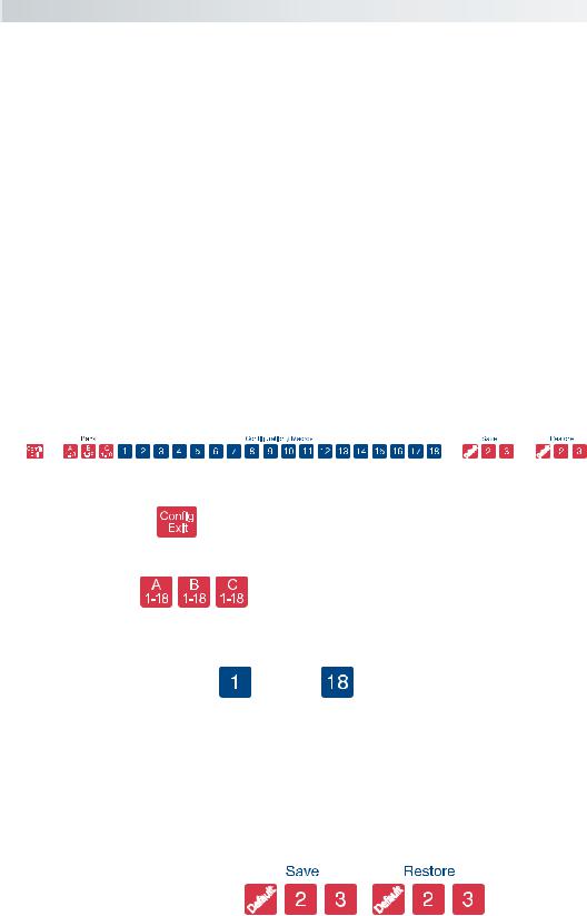
Overview of the Menu Strip For Use With the Optional Serial Interface Only
The Menu Strip is composed of:
Config/Exit Key
The Config/Exit key turns Configuration Mode On and Off.
3 Bank Keys
There are three Bank keys: A, B and C. Each bank has a different set of tablet options that are available through Configuration key combinations.
18 Configuration Keys |
through |
The keys numbered 1-18 can be used as both Configuration and Macro keys. When the tablet is in Configuration Mode, the keys function as Configuration keys. These keys allow you to set specific tablet options by turning different combinations of Configuration keys On or Off.
When Configuration Mode is Off, the keys function as Macro keys. Macros can be recorded only with the TabletWorks software (see TabletWorks Help).
3 Save and 3 Restore Keys
The Save and Restore keys work hand-in-hand. They are used to save, or recall/restore, a setup to or from one of three Save Areas. The tablet comes with three pre-programmed setups. You can use these setups directly or overwrite them with your own. The Default Save Key controls the first Save Area. The setup saved to this area is activated whenever you power up the digitizer. We recommend you save the setup you use most often as Default.

The DrawingBoard VI |
Tablet Customization |
15 |
Selecting a Pre-Programmed Setup
There are three pre-programmed setups available with DrawingBoard VI:
GTCO DP5 High Resolution Binary
Summagraphics MM 1201
CalComp 2000 ASCII
These setups are commonly used within software applications as required tablet formats. They are stored in Save Areas Default, 2, and 3, respectively. Check the manual that came with your software package to see if your application requires one of these pre-programmed setups. The Default setup is available when you power on the digitizer.
To select one of the other setups:
1 Turn on Configuration Mode by clicking on the Config/Exit
key.
2 Click on the desired Restore key.
3 Click on the Config/Exit key again to exit Configuration Mode.
The new setup is activated.
The following table lists the tablet options used by the pre-programmed setups.
|
Default |
Save 2 |
Save 3 |
Mode |
Run |
Track |
Point |
Baud Rate |
9600 |
9600 |
9600 |
Data Bits |
8 |
8 |
7 |
Parity |
None |
Odd |
Even |
Data Rate |
125 pps |
150 pps |
125 pps |
Resolution |
1000 lpi |
500 lpi |
200 lpi |
Output Format |
Format 23 |
Format 30 |
Format 0 |
Emulation |
GTCO DP5 |
Summagraphics |
CalComp 2000 |
|
High Resolution |
MM 1201 Binary |
ASCII |
|
Binary |
|
|
 Loading...