

Page 1
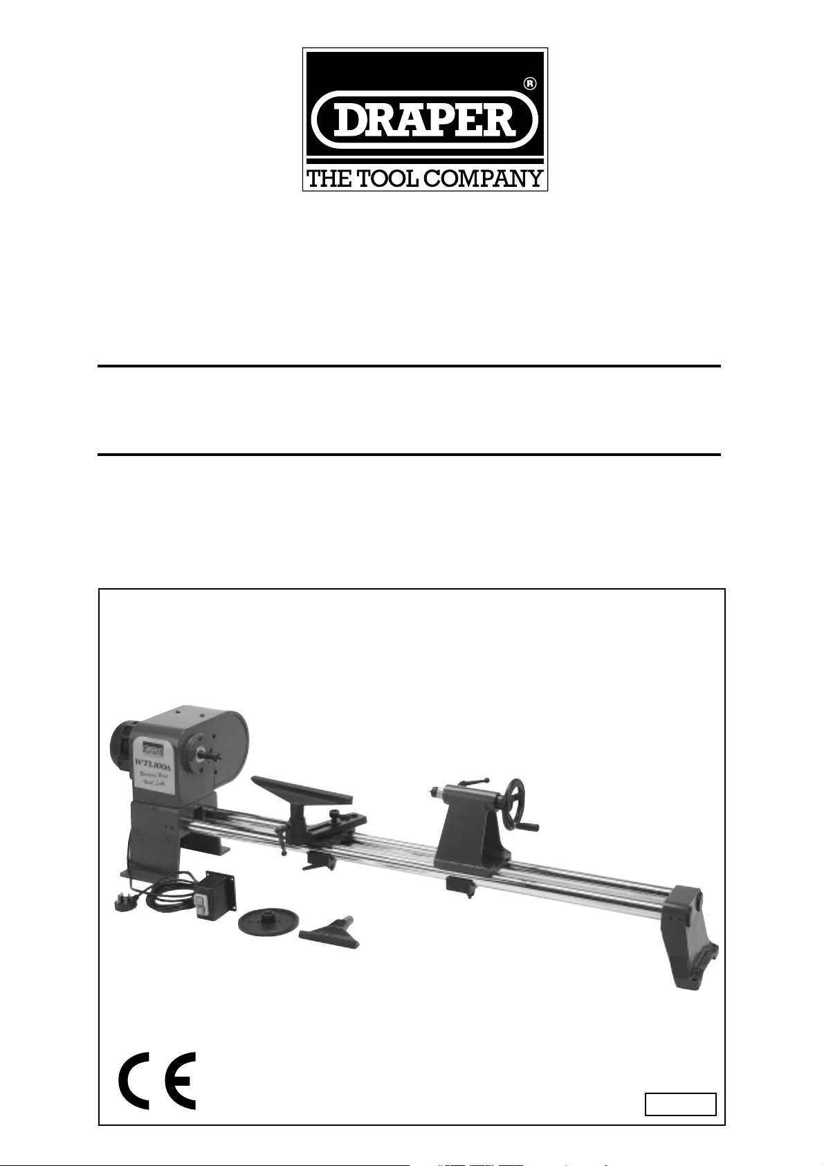
REVOLVING HEAD
WOOD LATHE
• INSTRUCTIONS •
IMPORTANT: PLEASE READ THESE INSTRUCTIONS CAREFULLY TO
ENSURE THE SAFE AND EFFECTIVE USE OF THIS TOOL.
STOCK No.58410 PART No.WTL100A
08/2000
Page 2

- 2 -
REVOLVING HEAD
WOOD LATHE
■ STOCK No.58410. ■ PART No.WTL100A
Whilst every effort has been made to ensure accuracy of information given in this manual is correct at the
time of going to print, the Draper Tools policy of continuous improvement determines the right to change
specification without notice.
CONTENTS: Page Nos.
Declaration of Conformity.................................................................................................................. 2
Specification / Guarantee................................................................................................................... 3
Power supply...................................................................................................................................... 4
General Safety Rules .......................................................................................................................... 5
Additional Safety Rules for Wood Lathes ............................................................................................ 6
Know Your Wood Lathe ....................................................................................................................... 6
Unpacking/Assembly......................................................................................................................... 7-13
Wood Lathe Adjustments - Changing speeds..................................................................................... 14
Wood Lathe Adjustments - Head Stock Position ................................................................................. 14
Wood Lathe Adjustments - Cup Centre Adjustment ........................................................................... 15
Wood Lathe Adjustments - Tool Rest ................................................................................................. 16
Trouble Shooting ............................................................................................................................... 17
Optional Accessories ........................................................................................................................ 17
We
Draper Tools Ltd. Hursley Road, Chandler's Ford, Eastleigh, Hampshire. SO53 1YF. England.
Declare under our sole responsibility that the product:
Stock No.:-58410. Part No.:-WTL100A.
Description:- Revolving Head Wood Lathe.
To which this declaration relates is in conformity with the following directive(s)98/37/EC, 73/23/EEC and
89/336/EEC.
With reference to:BS EN 60204-1:1993.
JOHN DRAPER
Managing Director 08/2000
DECLARATION OF CONFORMITY
Page 3

Draper machine tools have been carefully tested and inspected before shipment and are guaranteed to
be free from defective materials and workmanship for a period of 12 months from the date of purchase
except where tools are hired out when the guarantee period is ninety days from the date of purchase.
Should the compressor develop any fault, please return the complete tool to your nearest authorised
warranty repair agent or contact Draper Tools Limited, Chandler's Ford, Eastleigh, Hampshire, SO53 1YF.
England. Telephone: (023) 8026 6355.
If upon inspection it is found that the fault occurring is due to defective materials or workmanship, repairs
will be carried out free of charge. This guarantee does not apply to normal wear and tear, nor does it
cover any damage caused by misuse, careless or unsafe handling, alterations, accident, or repairs
attempted or made by any personnel other than the authorised Draper warranty repair agent.
This guarantee applies in lieu of any other guarantee expressed or implied and variations of its terms are
not authorised.
Your Draper guarantee is not effective unless you can produce upon request a dated receipt or invoice to
verify your proof of purchase within the 12 month period.
Please note that this guarantee is an additional benefit and does not affect your statutory rights.
Draper Tools Limited
SPECIFICATION
- 3 -
GUARANTEE
Stock No................................................................................................................................................58410
Part No............................................................................................................................................WTL100A
Turning Capacity Diameter........................................................................................................310mm (12")
Turning Capacity Length..........................................................................................................1000mm (39")
Motor...............................................................................................................................................370WATT
Voltage...................................................................................................................................................230V
Speeds (RPM).........................................................................................................475, 830, 1350, 2210, 3300
Spindle Taper...........................................................................................................................................MT1
Maximum Length......................................................................................................................1700mm (67")
Spindle Thread Size.....................................................................................................................
3
/4" x 16 TPI
Weight (Complete Machine) Nett/Gross...........................................................................................74/78kg
Sound Pressure Level (Max.)..............................................................................................................75dB(A)
Page 4
- 4 -
POWER SUPPLY
CONNECTING YOUR MACHINE TO A POWER SUPPLY
To eliminate the possibility of an electric shock your machine has been fitted with a BS approved, nonrewireable moulded plug and cable which incorporates a fuse, the value of which is indicated on the pin
face of the plug. Should the fuse need to be replaced an approved BS1362 fuse must be used of the
same rating, marked thus . The fuse cover is detachable, never use the plug with the cover omitted. If
a replacement fuse cover is required, ensure it is of the same colour as that visible on the pin face of the
plug (i.e. red). Fuse covers are available from your Draper Tools stockist.
If the fitted plug is not suitable, it should be cut off and destroyed. *The end of the cable should now be
suitably prepared and the correct type of plug fitted. See below.
*WARNING: A plug with bare flexible wires exposed is hazardous if engaged in a live power socket
outlet.
WARNING:THIS APPLIANCE MUST BE EARTHED
Green and yellow - Earth, Blue - Neutral, Brown - Live. As these colours may not correspond with the
coloured markings identifying the terminals in your plug proceed as follows: The wire which is coloured
green and yellow must be connected to the terminal in the plug which is marked with the letter ‘E’ or by
the earth symbol or coloured green and yellow. The wire which is coloured blue must be connected to
the terminal which is marked with the letter ‘N’ or coloured black or blue. The wire which is coloured
brown must be connected to the terminal which is marked with the letter ‘L’ or coloured red or brown.
EXTENSION LEAD CHART:
Extension lead sizes shown assure a voltage drop of not more than 5% at rated load of tool.
3 6 10 13
Extension cable length Wire Size mm
2
7.5m 0.75 0.75 1.0 1.25
15m 0.75 0.75 1.0 1.5
22.5m 0.75 0.75 1.0 1.5
30m 0.75 0.75 1.25 1.5
45m 0.75 1.25 1.5 2.5
Ampere rating
(on Name plate)
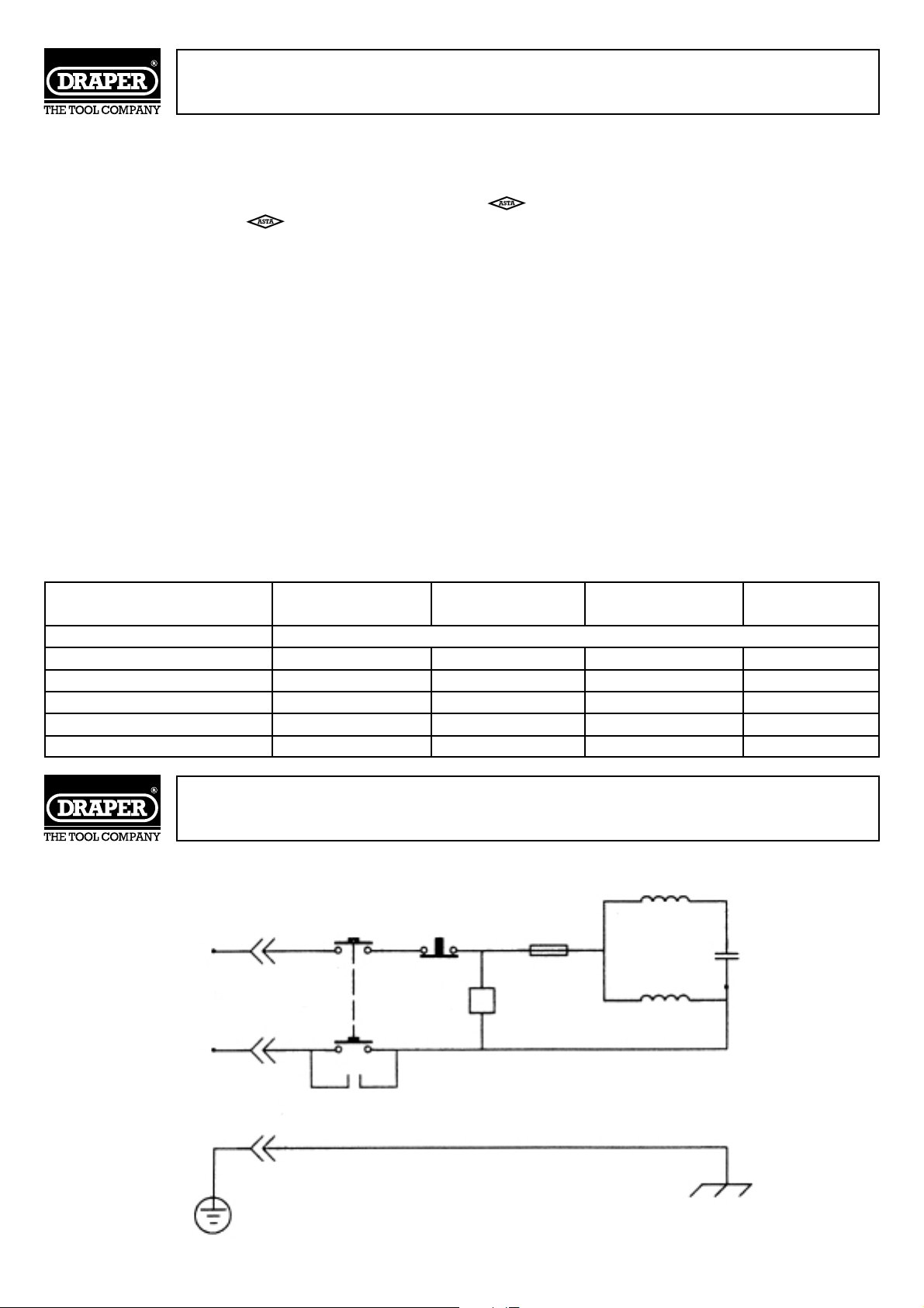
WIRING DIAGRAM
L
N
~
E
E
Yellow/Green
wire
Grounded
Red wire
Whire wire
Capacitor
Whire wire
Auxiliary winding
Thermal fuse
“O”
“1”
XS
XP
∏
J
Main
winding
Page 5

- 5 -
SAFETY WARNING
WARNING:
Please read the following instructions carefully. Failure to do so could lead to serious personal injury.
IMPORTANT:
Draper Tools recommends that this woodlathe should not be modified or used for any application other
than that for which it was designed. If you are unsure of it’s relative applications do not hesitate to contact
us in writing and we will advise you.
GENERAL SAFETY RULES
1. KNOW YOUR MACHINE TOOL
Read and understand the owner’s manual and labels
affixed to the tool. Learn its application and limitations
as well as the specified potential hazards peculiar to this
tool.
2. EARTH ALL TOOLS
This tool is equipped with an approved 3-core cable.
The green and yellow conductor in the core is the earth
wire. NEVER connect the yellow and green wire to a live
terminal.
3. KEEP GUARDS IN PLACE
and in working order.
4. REMOVE ADJUSTING KEYS AND WRENCHES
For a habit of checking to see that keys and adjusting
wrenches are removed from tool before turning it on.
5. KEEP WORK AREA CLEAN
Cluttered areas and benches invite accidents. Floor must
not be slippery due to oil or sawdust.
6. AVOID DANGEROUS ENVIRONMENTS
Do not use power tools in damp or wet locations or
expose them to rain. Keep the work area well lit. Provide
adequate surrounding work space.
7. KEEP CHILDREN AWAY
All visitors should be kept a safe distance from work
area.
8. MAKE WORKSHOP CHILDPROOF
with padlocks, master switches or by removing starter
keys.
9. DO NOT FORCE TOOL
It will do the job better and safer at the rate for which it
was designed.
10. USE RIGHT TOOL
Do not force tool or attachment to do a job for which it
was not designed.
11. WEAR PROPER CLOTHING
Do not wear loose clothing, gloves, neckties or
jewellery (rings, wristwatches) to catch in moving parts.
NON SLIP footwear is recommended. Wear protective
hair covering to contain long hair. Roll long sleeves
above the elbow.
12. USE SAFETY GOGGLES (Head Protection)
Wear safety goggles (must comply with BS 2092) at all
times. Normal spectacles only have impact resistant
lenses, they are NOT safety glasses. Also use a face
mask or dust mask if cutting operation is dusty and ear
protectors (plugs or muffs) during extended periods of
operation.
13. SECURE WORK
Use clamps or a vice to hold work. This frees
both hands to operate tool.
14. DO NOT OVERREACH
Keep proper footing and balance at all times.
15. MAINTAIN TOOLS WITH CARE
Keep tools sharp and clean for best and safest
performance. Follow instructions for lubricating
and changing accessories.
16. DISCONNECT POWER TO THE TOOLS
Before servicing, when changing accessories
such as cutters etc.
17. AVOID ACCIDENTAL STARTING
Make sure switch is in ‘OFF’ position before
plugging in the cable to the power supply.
18. USE RECOMMENDED ACCESSORIES
Consult the owner’s manual for recommended
accessories. Follow the instructions that
accompany the accessories. The use of improper
accessories may cause hazards.
19. NEVER STAND ON TOOL
Serious injury could occur if the tool is tipped or
if the cutting tool is accidentally contacted. Do
not store materials above or near the tool such
that is necessary to stand on the tool to reach
them.
20. CHECK DAMAGED PARTS
Before further use of the tool, a guard or other
part that is damaged should be carefully checked
to ensure that it will operate properly and
perform its intended function. Check for
alignment of moving parts, breakage of parts,
mounting and any other conditions that may
affect its operation. A guard or other part that is
damaged should be properly repaired or
replaced.
21. DIRECTION OF FEED
Feed work into a blade or cutter against the
direction of rotation of the blade or cutter only.
22. NEVER LEAVE THE MACHINE RUNNING
UNATTENDED
Turn power off. Do not leave the machine until it
comes to a complete stop.
Page 6
- 6 -
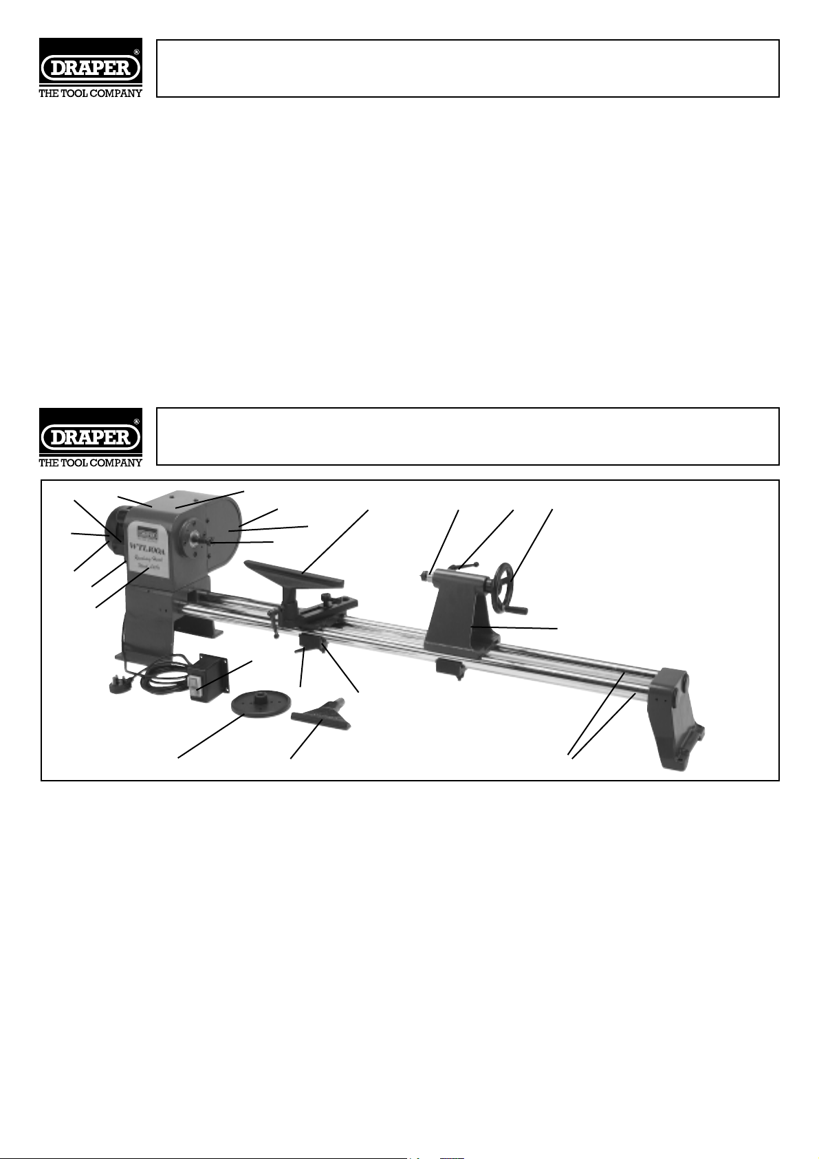
✪✌ Nameplate.
✫✌ Drive belt.
✬✌ Motor pulley - 5 speed manual change.
✭✌ ON/OFF No Volt Switch.
✮✌ Tool rest clamping bracket.
✯✌ Tool rest lock handles - locks rest in
required position.
✰✌ Bed bars - supports tailstock/tool rest.
✱✌ Tailstock adjustment handle wheel.
✲✌ Tailstock adjustment locking handle - locks
tailstock barrel in position.
✳✌ Live centre - acts as a pivot for the free end
of the workpiece.
ADDITIONAL SAFETY RULES FOR WOOD LATHES
KNOW YOUR WOOD LATHE
FOR YOUR OWN SAFETY: Read and understand this instruction manual before operation.
1. Always wear eye protection which complies to a recognized standard.
2. Wear a mask or respirator when dust is generated.
3. Keep hands clear of moving parts.
4. Only use Draper approved accessories and spare parts.
5. Keep turning chisels sharp.
6. Keep guards in place and working properly.
7. Never reach behind or beneath the workpiece.
8. Disconnect from the power supply before adjusting or servicing.
9. To avoid electric shock do not use in damp conditions.
✴✌ Tool rests, 6" and 12" supplied - supports
chisel.
✵✌ Motor.
✶✌ Drive spur - drive centre for workpiece.
✷✌ Spindle pulley - 5 speed manual change.
✸✌ Pulley cover - protects user from moving
parts.
✹✌ Tailstock assembly - supports long
workpieces.
✺✌ Headstock.
✻✌ Spindle.
✼✌ Belt tension lever.
✽✌ Face plate.
✪✌
✫✌
✬✌
✭✌
✮✌
✱✌
✯✌
✰✌
✲✌
✳✌
✴✌
✵✌
✶✌
✷✌
✸✌
✹✌
✺✌
✼✌
✻✌
✴✌
✽✌
Page 7
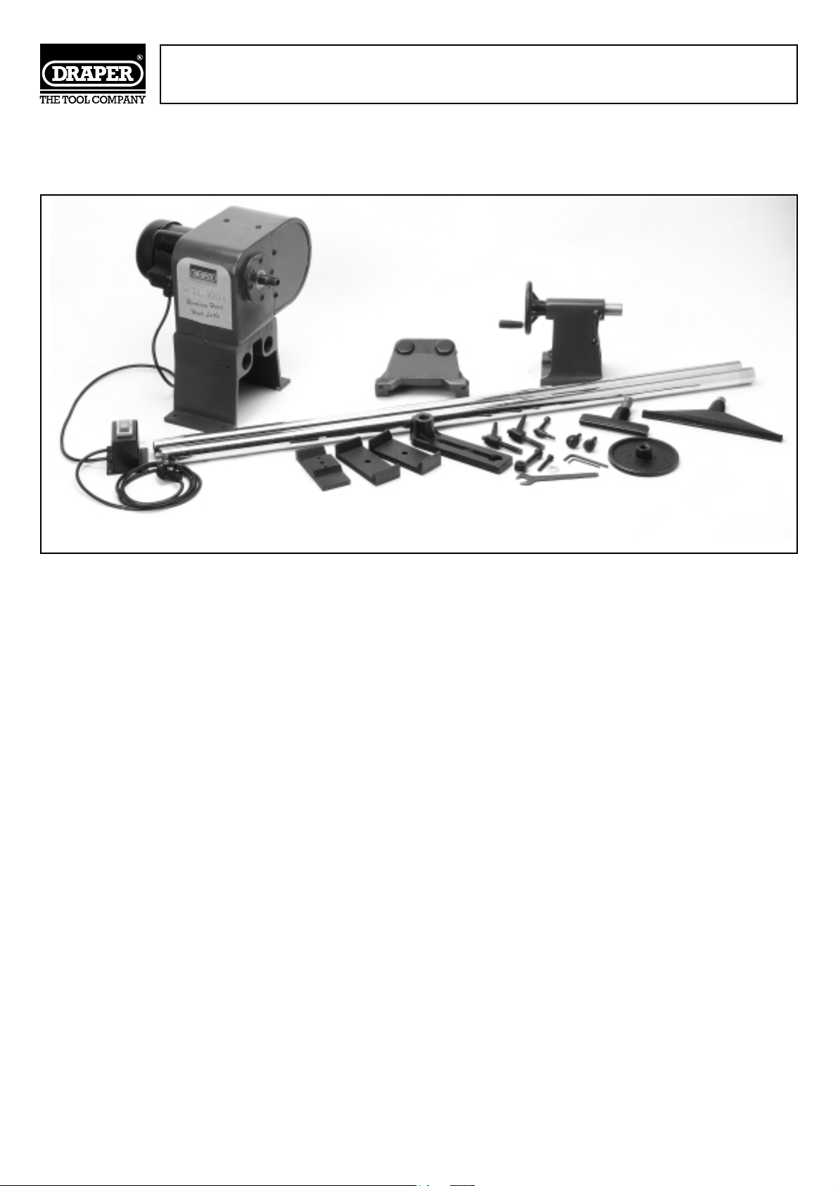
UNPACKING AND CHECKING CONTENTS
Carefully unpack the wood lathe and all the loose parts from the carton. Fig.1. illustrates the wood lathe
and all the associated parts that are packed in the carton. Now check that all the parts are present.
Fig.1.
Please contact the Draper stockist where your purchase was made if you have any enquiries, eg problems
with assembly, missing/damaged parts, help with accessories available or technical advice or
alternatively, call the Draper Helpline on (023) 8049 4344.
- 7 -
Page 8
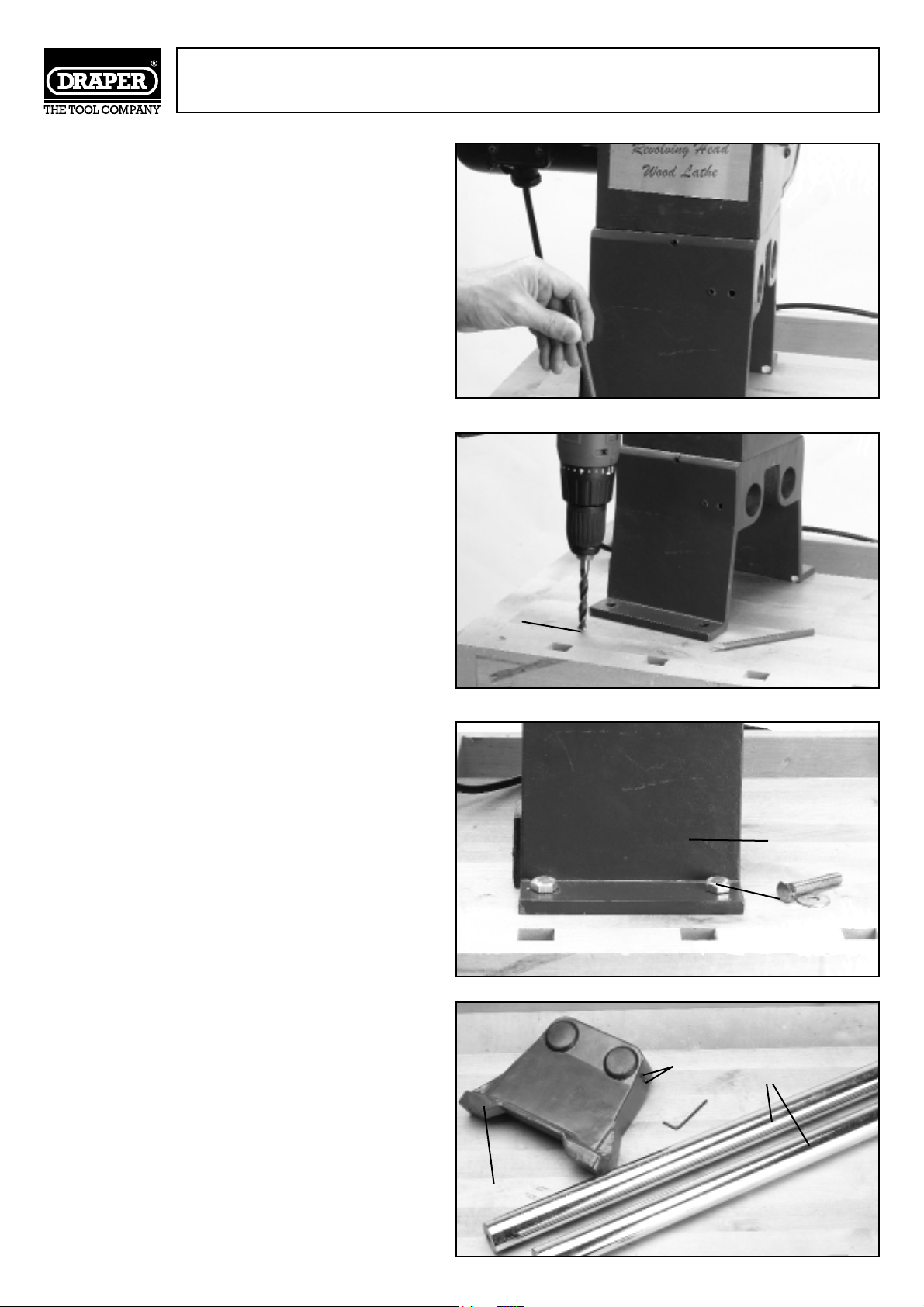
ASSEMBLY
IMPORTANT:
To correctly assemble and adjust this wood lathe,
please read the following instructions carefully.
NOTE - To secure the wood lathe to a workbench
or stand, you will need to obtain nuts, bolts and
washers (these are not supplied).
SECURING: Position the wood lathe on the
workbench/stand (optional accessory) before
drilling the locations holes, this will ensure correct
alignment. Mark and drill four holes ✪✌ (Figs.2 &
3) in the top of the workbench/stand to the
required size as shown. Ensure the headstock is
positioned so that you do not drill into the legs or
support rails underneath.
Carefully lift the headstock ✫✌Fig.4. onto the
workbench/stand. Now line up the holes in the
base of the headstock with the holes you have
drilled in the top of the workbench/stand. Insert
one bolt ✭✌ into each of the four holes. Now
place a flat washer, lock washer and nut onto each
of the bolts. Tighten nuts finger tight only.
From the loose parts, locate the two bed bars ✮✌,
bed bar foot ✯✌ and grub screws ✰✌ Fig.5.
Fig.2.
Fig.3.
Fig.4.
Fig.5.
- 8 -
✪✌
✫✌
✭✌
✯✌
✰✌
✮✌
Page 9
ASSEMBLY Cont'd.
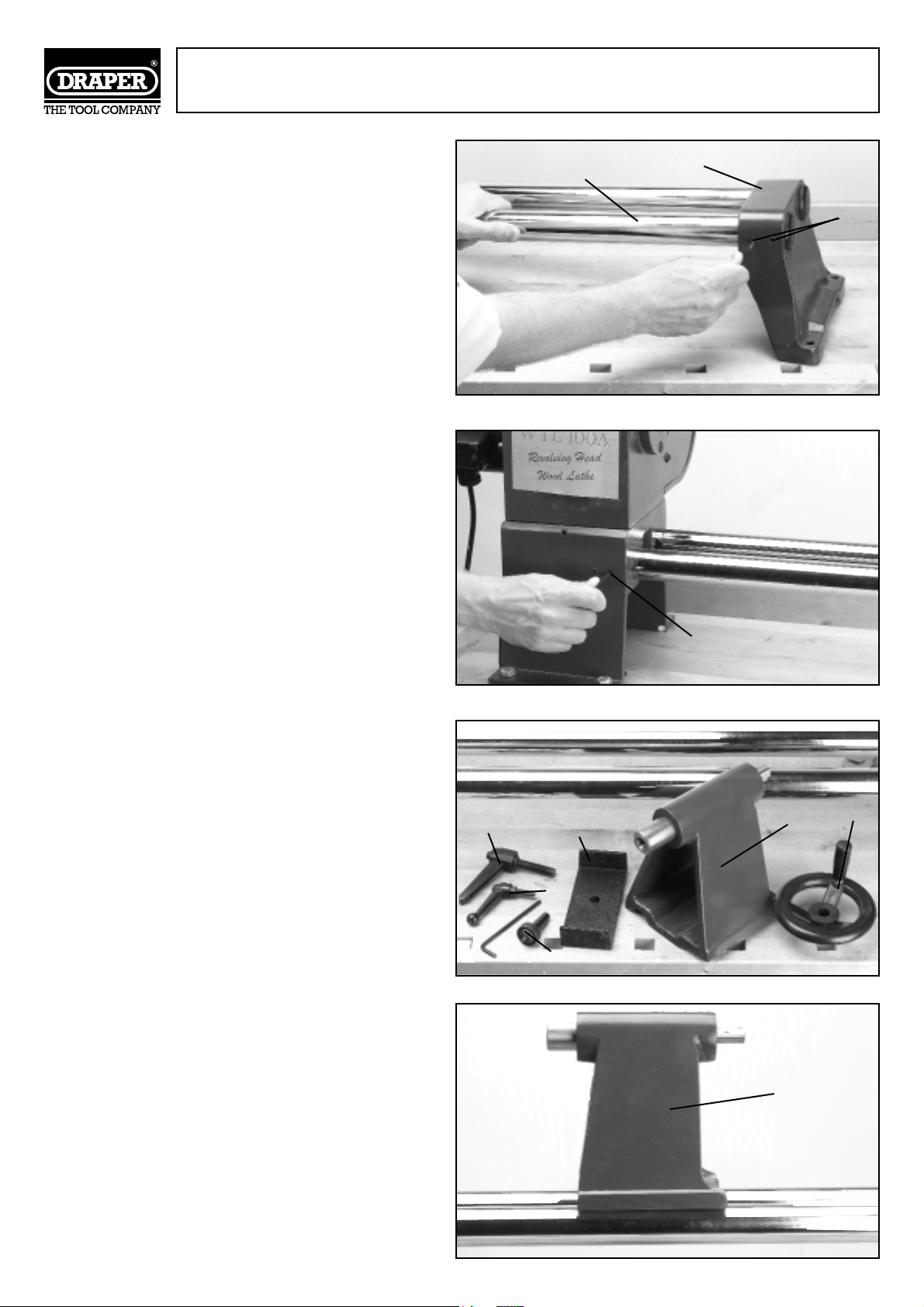
Place each of the bed bars ✮✌ into the holes ✱✌
located in the bed bar foot and secure by
tightening the hexagon socket head screws ✰✌
as shown in Fig.6.
Now slide the bed bars into the headstock and
secure by tightening the two hexagon socket
head screws ✲✌ see Fig.7.
Next, from the loose parts supplied locate the
following parts; tailstock assembly ✳✌, locking
handle ✵✌and ✴✌, base plate ✶✌, hand wheel
✷✌and finally centre cup ✸✌see Fig.8.
Place the tailstock assembly ✳✌ on the bed bars
as shown in Fig.9.
Fig.6.
Fig.7.
Fig.8.
Fig.9.
- 9 -
✮✌
✱✌
✰✌
✲✌
✳✌
✴✌
✵✌
✶✌
✸✌
✷✌
✳✌
Page 10
ASSEMBLY Cont'd.
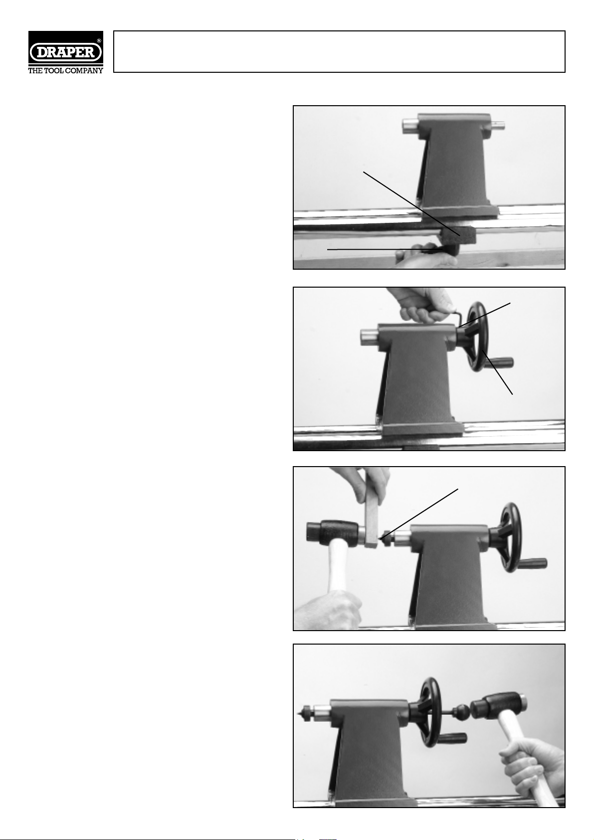
Then secure in place using the base plate ✶✌
and locking handle ✴✌as shown in Fig.10.
Secure the handwheel ✷✌to the tailstock
assembly by tightening the hexagon socket
head screw ✹✌ as shown in Fig.11.
Slide the centre cup ✸✌ into the tailstock barrel
as shown in Fig.12. Note: do not drive or hammer
the centre cup into the tailstock barrel as
removal maybe difficult. Use a soft faced
hammer and a block of wood to gently tap it in
as shown in Fig.12.
To remove the centre cup from the tailstock
barrel insert the ejection pin (supplied), a small
wooden dowel or brass rod into the rear of the
barrel. Hold the cup with one hand and gently
tap the pin with the hammer until it is released.
See Fig.13.
Fig.10.
Fig.13.
Fig.11.
Fig.12.
- 10 -
✶✌
✴✌
✹✌
✸✌
✷✌
Page 11
ASSEMBLY Cont'd.
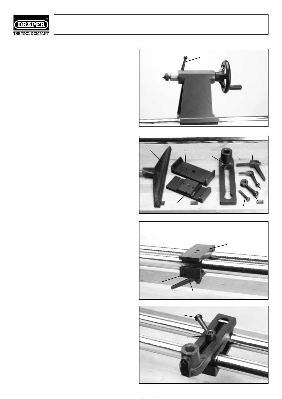
Finally insert locking handle ✵✌ as shown in
Fig.14.
Now locate the following from the loose parts
supplied with the wood lathe; tool rest ✺✌,
base plate ✻✌, locking handle ✼✌, top plate
✽✌, locking handle ✾✌, tool rest support ✿✌,
bolt ❀✌ and finally handle ❁✌. See Fig.15.
Secure the base plate ✻✌to the top plate ✽✌
using the locking handle ✼✌as shown in
Fig.16.
The tool rest support can now be attached to
the top plate as shown in Fig.17 using the bolt
❀✌and handle ❁✌.
Fig.14.
Fig.17 .
Fig.15.
Fig.16.
- 11 -
✵✌
✺✌
✻✌
✽✌
❁✌
✾✌
✼✌
✿✌
✻✌
✽✌
✼✌
❀✌
❁✌
❀✌
Page 12
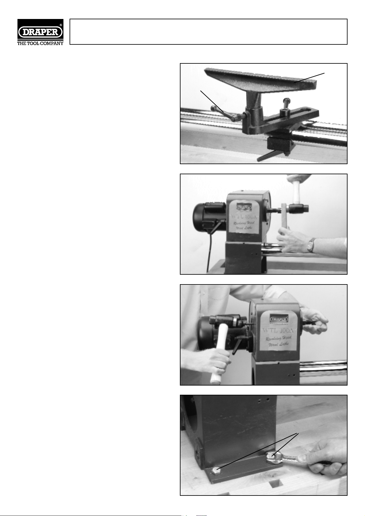
ASSEMBLY Cont'd.
Finally insert the tool rest ✺✌ into the support
and secure using locking handle ✾✌ Fig.18.
Now locate the headstock spindle. Note: Do not
drive or hammer the drive centre into the
spindle as removal may be difficult. Use a soft
faced hammer and a piece of softwood as
shown in Fig.19.
To remove the drive spur from the headstock
spindle insert the ejection pin, a wooden dowel
or brass rod through the hole in the rear of the
headstock, hold the drive spur with one hand
and gently tap the dowel or rod with a hammer
until it is released. See Fig.20.
Tighten the four nuts and bolts ❂✌Fig.21 so that
the headstock is securely fixed to the
workbench/stand.
Fig.18.
Fig.19.
Fig.20.
Fig.21.
- 12 -
✺✌
✾✌
❂✌
Page 13
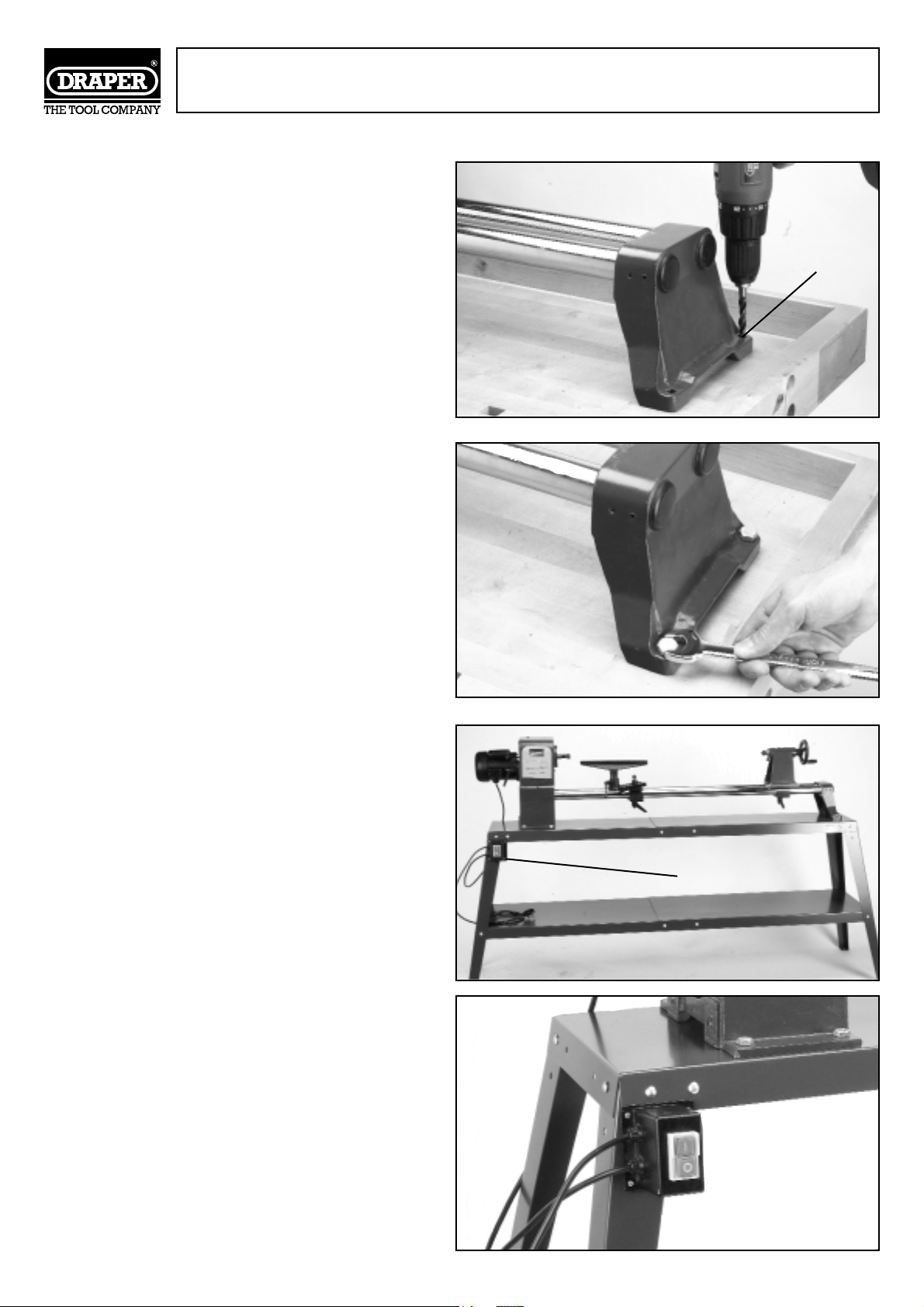
ASSEMBLY Cont'd.
Now mark the two drill holes in the
workbench/stand through the bed bar foot fixing
holes ❃✌ as shown in Fig.22.
Insert one bolt into each of the holes. Now place
a flat washer and nut onto each of the bolts and
tighten. See Fig.23.
We recommend the switch and cable are
mounted on the side of the workbench or on the
leg of the wood lathe stand (optional
accessory)(Fig.24A & B). This will ensure the
cable is not pulled up into the workings when
the headstock is rotated for spinning up larger
pieces of work. Once a safe position is found the
holes should be marked and drilled. Secure the
switch box to the stand with suitable fixings ✪✌
(not supplied) as shown.
Note: Make sure the switch is easily accessable
in the event of an emergency.
Fig.22.
Fig.23.
Fig.24A.
- 13 -
❃✌
✪✌
Fig.24B.
Page 14
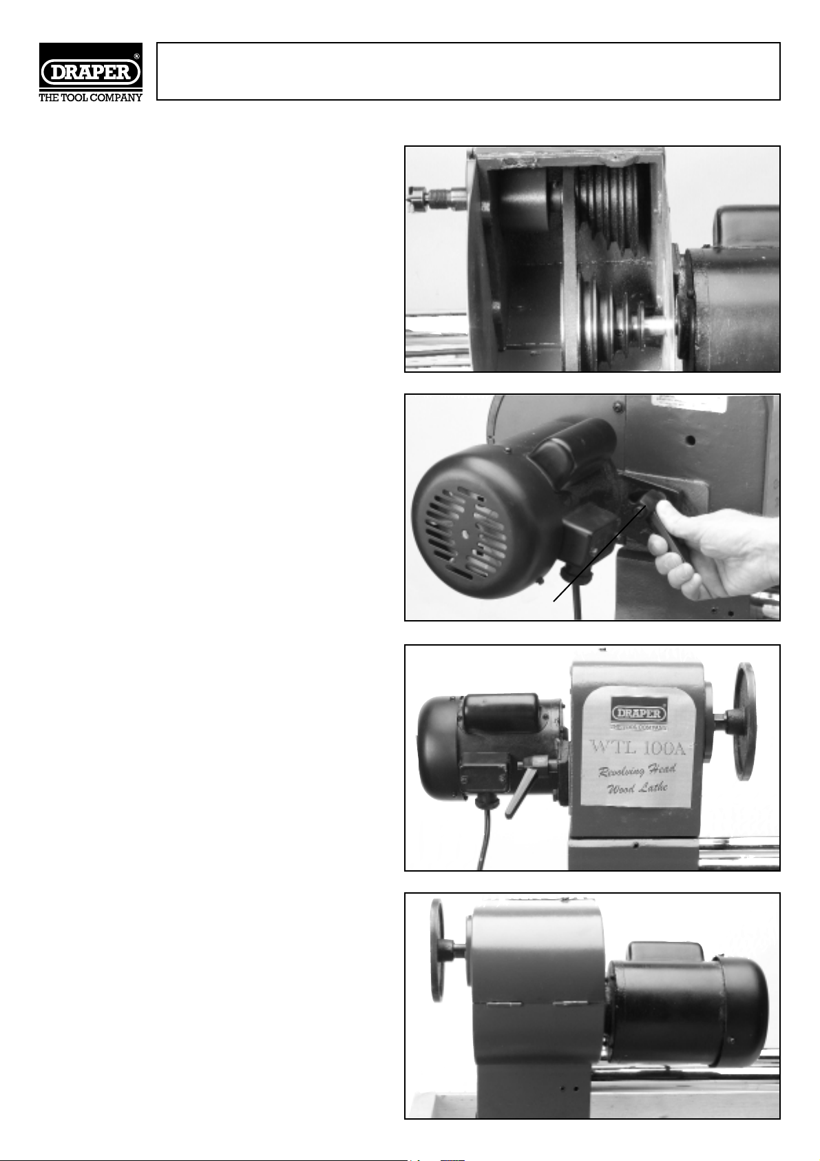
WOOD LATHE ADJUSTMENTS
CHANGING SPEEDS
Fig.25 shows the belt on the outside end of the
pulleys. In this position the spindle will turn at
maximum rpm, should you want to run the lathe
at a slower speed, you must move the belt
inwards.
IMPORTANT:- Ensure the wood lathe is
disconnected from the power supply before
making any adjustments. If you want to increase
the speed move the belt outwards. The drive belt
can be moved as follows:
Release the motor locking handle ✫✌Fig.26.
Move the motor inwards, move belt to the
required position, retension belt by moving
motor outwards then tighten locking handle ✫✌.
HEADSTOCK POSITION ADJUSTMENT
The headstock assembly has three preset
positions these are shown in Figs.27, 28 and 29.
To move the headstock release locking lever ✬✌
Fig.30 and turn the head in a clockwise direction
until the head is in the required position then
tighten locking lever ✬✌Fig.30.
Fig.25.
Fig.26.
Fig.28.
Fig.27.
- 14 -
✫✌
Page 15
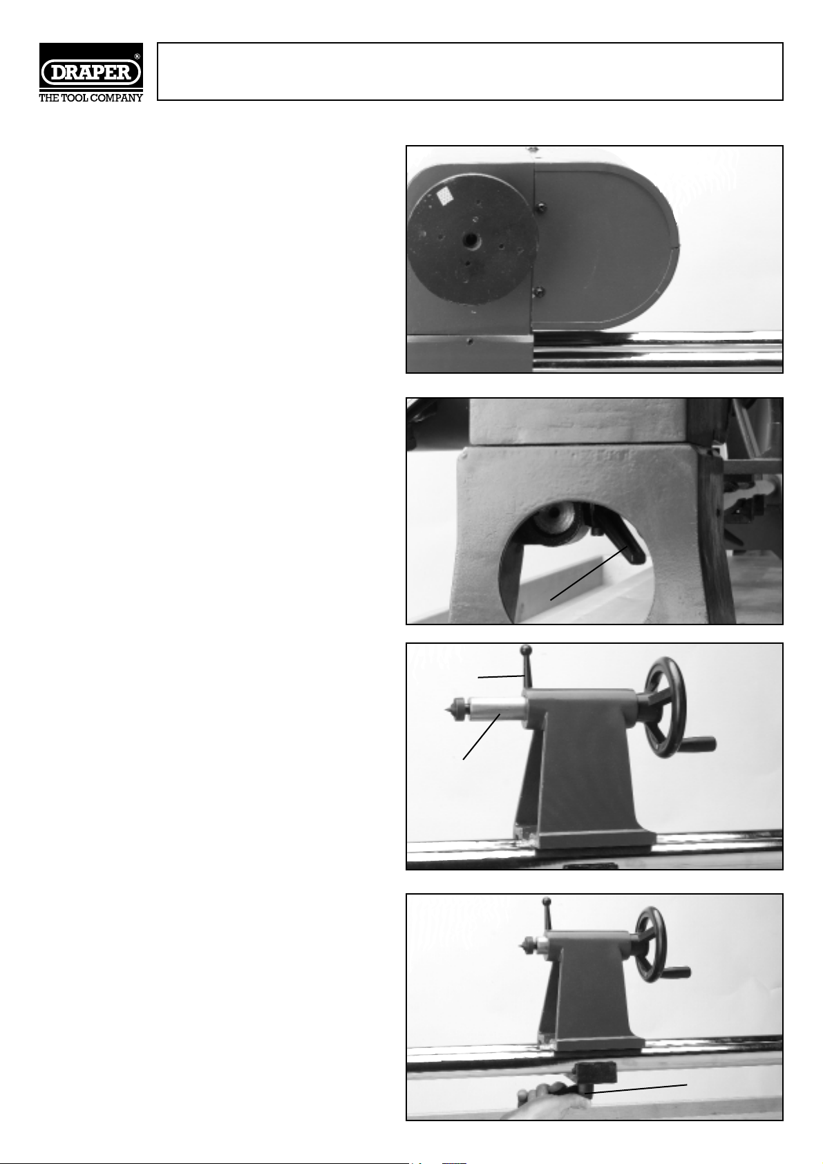
- 15 -
WOOD LATHE ADJUSTMENTS Cont'd.
CUP CENTRE ADJUSTMENT
The cup centre located in the tailstock barrel ✭✌
supports the workpiece when spindle turning.
The cup centre barrel maybe adjusted as
follows: Release locking handle ✮✌ and turn the
handwheel clockwise to decrease the distance
between the centres, and turn the handwheel
anticlockwise to increase the distance between
the centres (Fig.31).
Once in position secure in place by tightening
lock knob ✮✌. The tailstock assembly can be
moved to any part of the bed bars, loosen
locking lever ✯✌(Fig.32), move to the required
position and retighten.
Fig.29.
Fig.32.
Fig.30.
Fig.31.
✮✌
✬✌
✭✌
✯✌
Page 16
-16 -
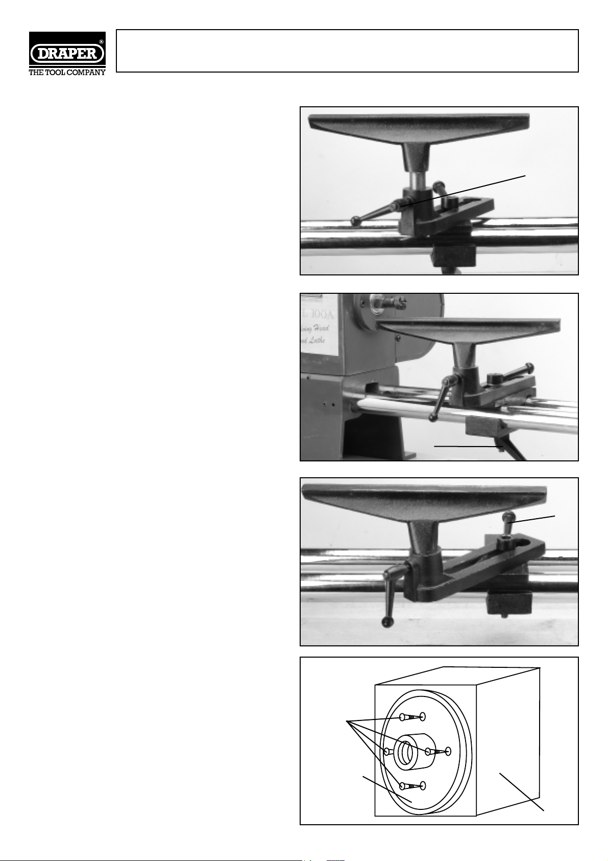
TOOL REST ADJUSTMENT
The following adjustments can be made to the
tool rest assembly:
Height - The height of the tool rest can be
adjusted by loosening locking lever ✰✌ Fig.33
moving the tool rest to the required height and
tightening the locking lever.
Positioning - (length)- The tool rest assembly
can be moved along the length of the bed bar
assembly. Loosen locking lever ✱✌Fig.34 move
to the required position and retighten.
Positioning - (width)- The tool rest can be closer
or further away from the workpiece as required.
Loosen lever ✲✌Fig.35 move to the required
position and retighten lever.
Mounting woodstock onto a faceplate: there are
several ways in which you can mount the stock
onto a conventional face plate, the most common
way used is shown in Fig.36.
WOOD LATHE ADJUSTMENTS Cont'd..
Fig.33.
Fig.34.
Fig.35.
✰✌
✱✌
✲✌
Fig.36.
SCREWS
FACE PLATE
WOOD
STOCK
Page 17
- 17 -
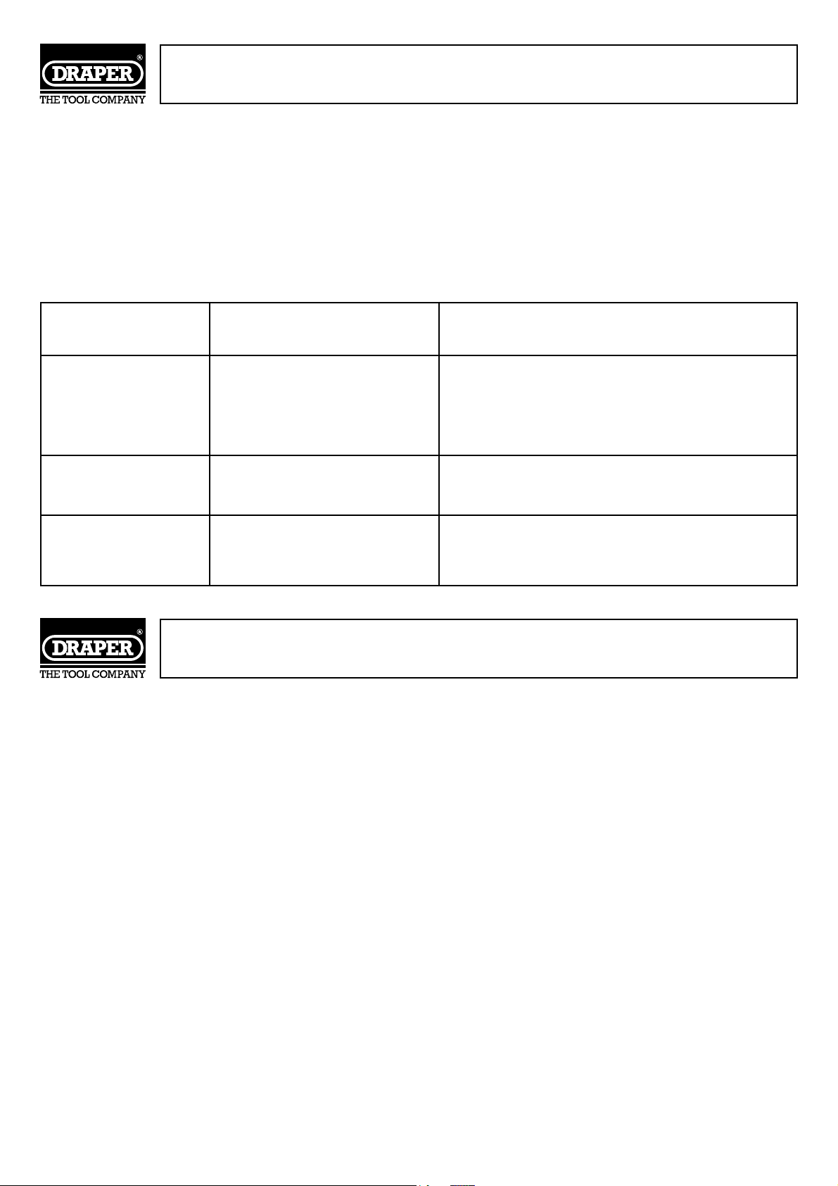
TROUBLESHOOTING
WARNING:
FOR YOUR SAFETY ALWAYS TURN THE MAIN SWITCH ON
THE MACHINE ‘OFF’ AND REMOVE THE PLUG FROM THE
POWER SUPPLY BEFORE CARRYING OUT ANY
MAINTENANCE OR TROUBLESHOOTING
Motor will not run. 1. Defective On-Off switch.
Defective switch cord.
2. Burned out motor.
1. Replace defective parts before using
Lathe.
2. Any attempt to repair this motor may
cause a HAZARD unless repair is done by
a qualified service technician.
Lathe slows down. 1.V-belt too loose. 1. Adjust belt tension, see Basic Lathe
Operations
Wood burns at
tailstock end.
1. Live centre too tight or
not lubricated.
1. Back off tailstock barrel and lubricate live
centre
TROUBLE PROBABLE CAUSE REMEDY
OPTIONAL ACCESSORIES
Wood Lathe Stand
Stock No.63196
Part No.AWL18
Combination Chuck
Stock No.37168
Part No.AWL40
Face Shield
Stock No.33831
Part No.FS8
A full range of wood turning accessories are shown in the Draper Catalogue.
Page 18

- 18 -
NOTES
Page 19

NOTES
- 19 -
Page 20

DRAPER TOOLS LTD.
Hursley Road, Chandler’s Ford,
Eastleigh, Hants. SO53 1YF. England.
Tel: (023) 8026 6355.
Fax: (023) 8026 0784.
Helpline: (023) 8049 4344.
YOUR DRAPER STOCKIST
©Published by Draper Tools Ltd.
No part of this publication may be reproduced,
stored in a retrieval system or transmitted in any
form or by any means, electronic, mechanical
photocopying, recording or otherwise without
prior permission in writing from Draper Tools Ltd.
www.draper.co.uk
e-mail: [email protected]
 Loading...