

Page 1
Page 2

TABLE OF CONTENTS
SECTION
I
II
III
IV
SPECIFICATIONS
INSTALLATION
OPERATION
SERVICING
ILLUSTRATIONS AND TABLES
Figure 1
Figure 2
Figure 3
Figure 4
Figure 5
Figure 6
Figure 7
Rear View
Viewing Angle Options 8
Front View 11
Block Diagram
Bottom View
Top View
Schematic Diagram
PAG E
l - 3
4
-
9
-
17
-
PAGE
6
22
23
24
25
8
16
20
Table I
Table II
Tube Voltages
Resistance to Ground
21
21
Page 3

Section I
Specifications
1.1
l.2
TUNING RANGES
Band
.2
.5
1.0
6.0
7.0
9.5
11.5
15.0
17.5
21.5
25.5
SENSITIVITY
Frequencies Tuned (Megahertz)
.150
.450
.950
5.950
6.950
9.450
11.450
14.950
17.450
21.450
25.450
to
to
to
to
to
to
to
to
to
to
to
.500
1.050
1.550
6.550
7.550
10.050
12.050
15.450
18.050
22.050
26.050
The SW-4A has a signal-to-noise ratio of 10 decibels with an input signal of 1
.2 band) when the input signal is modulated 30% with 400
microvolt (3 microvolt
Hertz.
Simply stated, this means that you get 10 times as much signal output
on
as noise output from your receiver when you have a signal as small as 1 millionth of a volt on your antenna.
1.3
SELECTIVITY
The SW-4A has a bandwidth of 5 kilohertz at 6 dB down and 16 kilohertz at 60
down.
This selectivity gives adequate bandwidth for optimum reception without
allowing significant interference from stations operating near the frequency to
which you are tuned.
1.4
ANTENNA
The nominal input impedance of the antenna circuit is 52 ohms. This provides
excellent reception characteristics with
most commercial short-wave antennas,
/
while also giving good performance with properly installed long-wire antennas.
1.5
DIAL CALIBRATION
The tuning dial of the SW-4A is accurate to +- 3 KHz after calibration on a par-
ticular band.
1.6
Output impedances of 4 and 8 ohms are provided, The
audio output (volume) of 3 watts,
OUTPUT
SW-4A
has a maximum
At a 2 watt level, the harmonic distortion is
5%.
dB
Page 4

Section I
Specifications
1.7
STABILITY
After a five minute warm-up, the SW-4A will not drift more than 100 Hertz
above or below the frequency to which it is tuned, A 10% change in line
age,
either above or below the nominal value , will cause a frequency shift
volt-
of not more than 100 Hertz.
1.8
INTERMEDIATE FREQUENCIES
The first conversion is made at a frequency of 5,645 megahertz, the second
at .455 megahertz
1.9
AUTOMATIC GAIN CONTROL
An amplified-delayed automatic gain control circuit is used in the
dB
90
change in
. A crystal lattice filter is used in the first conversion.
SW-4
R,F,
input causes a 3 dB change in audio output, In other
A
words, the volume from the SW-4A does not change much from very weak sig-
nals to very strong signals.
1.10
The power consumption of the SW-4A is
POWER
30
watts.
1.ll
The SW-4A is
DIMENSIONS
5-l/2
inches high, 10-3/4 inches wide, and 12-l/4 inches deep,
It weighs 16 pounds.
1.12
TUBES AND SEMICONDUCTORS
The SW-4A uses 6 tubes, 7 transistors, and 8 semiconductor diodes, These
are listed on the next page.
Page 5

Section I
Specifications
1.12
TUBES AND SEMICONDUCTORS
Identification
vl
v2
v3
v4
v5
v6
Ql
Q2
Q3
Q4
Q5,
Q7
Dl
D2
D3
D4
D5, D6, D7, D8
Q6
Type
12BZ6
6HS6
12BE6
12BA6
12BA6
6HS6
2N3394
2N3858
2N706
2N3858
2N3394
RCA
40310
lN483
lN714
lN270
lN3194
lN3194
(cont’d.)
Function
Radio frequency amplifier
First mixer
Second mixer
First intermediate frequency
amplifier
Second intermediate frequency
a mplif ier
Premixer
Crystal oscillator
Buffer for variable frequency
oscillator
Variable frequency oscillator
Automatic gain control amplifier
Audio frequency amplifiers
Audio output
Automatic volume control
clamp
Volta ge regulator
Detector
Bias rectifier
Power supply rectifiers
Page 6

Section II
Installation
2.1
UNPACKING
Carefully remove the receiver from the shipping carton, and examine it for
evidence of damage
.
If any damage is discovered, immediately notify the
transportation company that delivered the receiver, Be sure to keep the shipping carton and packing material, as the transportation company will want to
examine them if there is a damage claim.
Keeping the carton and packing
material is recommended even when no shipping damage occurs, as having
the original carton available makes shipment of the receiver much easier
should it ever be necessary to return it to the factory for service.
On the front of this manual you will find a brown envelope, which contains a
warranty card and some hardware. Fill our the warranty registration card and
mail it, Lay the hardware aside temporarily. Turn your SW-4A so the rear of
the cabinet is facing you, and check that all tubes and crystals are firmly in
their sockets.
2.2
LOCATION
The SW-4A will work well in almost any location. Avoid placing it in an ex-
,
tremely hot area (such as over a radiator)
and do not restrict air circulation
around the receiver.It is best to leave an inch or more clearance on each
side of the receiver.
2.3
ANTENNAS
Your SW-4A is an excellent receiver, and should be used with an adequate an-
.
tenna system
A carefully
and located as high in the air as possible,
SW-4A. Commercially available antennas,
installed long wire
___
will give good reception with the
antenna, 50 to 75 feet in length,
such as the Mosely SWL-7, will
give even better results. In any case,a standard radio lightning arrester
should be installed in
the antenna
screw terminal (marked ANT) on the rear of the receiver.
hertz
use the accessory DRAKE AL-4 Shielded Directional Loop Antenna if
lead.
The
antenna lead is connected to a
For .15
- 1.5
mega-
directional reception is desired.
SW-4A
SPEAKER
requires an external speaker, which may have an impedance of
2 . 4
The
4 or 8 ohms.The Drake MS-4 Speaker, housed in a cabinet that matches the
SW-4A, provides excellent audio reproduction and comes equipped with a cable
terminated in a phono plug matching the 4 ohm output socket of the receiver,
Screw terminals
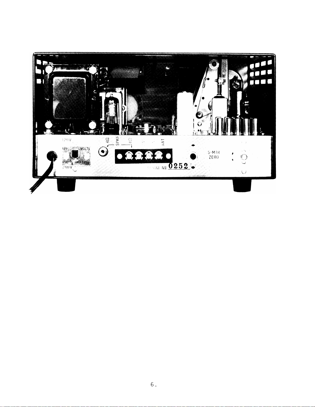
, marked 8 ohms and GND are provided on the rear of the SW-4A
for connection of speaker leads if an 8 ohm speaker is used. (See Figure 1).
4.
Page 7

Section II
Installation
2.5
HEADPHONES
Headphones having an impedance of 500 to 1000 ohms may be used with the
SW-4A. Best results will be obtained with a set of good quality 600 ohm headphones
at the bottom center of the front panel of the receiver, A standard
phono plug will mate with this socket.
The headphone connection is made through the socket marked PHONES
.
l/4
inch
Connecting the headphones to the
receiver will shut off the speaker output.
SW-4A
POWER
was shipped from the factory ready for operation from a 120 volt
3/4
ampere slo-blow fuse
3/4)
is installed in the fuseholder at the rear of the chassis.
,
no changes need be made.
,
your receiver is easily adapted to operation
2.6
Your
50 to 60 Hertz (cycles per second) power line. A
(Buss type MDL
If your receiver is to be operated on 120 volts
If your line voltage is 240 volts
at that voltage. Make sure the power cord is not connected. Turn the receiv-
er so the rear of it is facing you.
At the left side of the receiver, (see Figure
1) near the place where the power cord passes through the chassis, is a switch.
A copper plate surrounds the switch handle, and the plate is marked
3/4
use a
chassis,
the
amp. fuse.
remove the plate, and push the sliding handle of the switch down
as far as it will go.
3/8
amp. fuse” is toward you, and place the plate in position around the switch
Remove the two (2) screws holding the copper plate to
Turn the copper plate so the side marked
"120 volts",
”
240 volts use
"
handle.Install the two (2) screws to hold the copper plate in place, Remove
the knurled cap from the fuse holder (next to the power transformer on the top
3/4
rear of the chassis) and remove the
ampere slo-blow fuse (Buss type MDL
fuseholder cap,
Your receiver is now ready for operation on 240 volts.
ampere fuse, Obtain and install
3/8)
in the fuseholder and tighten the
3/8
2.7
The receiver should be connected to a ground that is as near as possible to
earth potential.
connection,
connection,
GROUNDING
A cold water pipe will usually
Either of the screw terminals
Use a commercial ground clamp for fastening the ground wire
make
a satisfactory ground
marked GND may be used for this
to the water pipe, and make sure the clamp makes solid physical contact with
the pipe.
2.8
VIEWING ANGLE OPTIONS
As supplied, your SW-4A sits with its base parallel to the mounting surface
as its front panel vertical to the mounting surface . Using the hardware that
was packed with your warranty registration card, it is possible to change the
viewing angle.
The top illustration in Figure 2 shows the SW-4A as supplied,
To change to the other mounting shown in Figure 2, it is necessary to remove
5.
,
Page 8
Section II
Installation
FIG. 1
the bottom cover of your SW-4A.
REAR
VIEW SW-4A
To do this, first obtain a piece of soft material, such as a rubber mat or a blanket, and place it on the work surface.
Turn the SW-4A upside down, and set it on its top cover, on the mat. You
will note two rows of three screws each on each side of your receiver.
To re-
move the bottom cover, remove the rows of three screws that are nearest the
bottom cover, and lift the cover from the receiver.
Next, remove the screws holding the rear mounting feet to the receiver, Near
the holes from which you removed the screws are two other holes,, Take the
small hemispherical rubber feet that were supplied, and snap the cylindrical
portion of these into the holes next to the screw holes,, If you want the view-
#l,
ing angle shown in Option
all that remains to be done is to put the bottom
cover back onto your receiver.
For mounting as shown in Option
#2,
remove the front mounting feet, invert
them, and remount them on the original mounting screws. Then take the two
threaded studs supplied (these look like bolts without heads) and thread them
into the bottom of the inverted mounting feet.
Now screw the mounting feet
that were removed from the rear of the receiver onto the protruding studs, (See
detail drawing at bottom of Figure 2).
Page 9

Section II
Installation
2.9
ACCESSORIES
In addition to the MS-4 matching speaker, a special loop antenna, Model AL-4
is available.
ASSEMBLY AND USE OF THE ACCESSORY AL-4 LOOP ANTENNA
Assembly
Your AL-4 Loop Antenna is shipped in five separate pieces; 4 struts and 1 body
piece.
and attached to the wire are 4 eyelets.
4 struts into the 4 holes in the aluminum disc part of the body piece.
The body piece has a length of coaxial wire attached at the handle-plug
To assemble the AL-4, first insert the
Either end
may be inserted. It will probably be easiest to do this with the antenna lying
.
horizontally on a table
struts .
The 4th eyelet is then inserted into the 4th strut by bending this strut
up out of the plane of the other struts;
Next insert 3 of the eyelets into the ends of 3 of the
be careful not to bend excessively so
that it will take a permanent set.When the struts and eyelets are in place,
the struts should form shallow “S’s”. This completes the assembly of the AL-4
Loop Antenna.
Use
The AL-4 Loop Antenna handle should be inserted into the hole on the top of
the SW-4A Shortwave Listening Receiver cabinet, and the plug inserted in the
jack on top of the chassis. The AL-4 is intended for use primarily on the 3
lowest bands. For directional effect, disconnect any antenna connected to the
antenna terminal at the rear of the chassis. The antenna is directional in that
it has a very sharp null in two directions. When using the AL-4 (or any other
antenna) quite often there will be interferring stations operating on the same
frequency. To best receive the desired signal, in the presence of an interferring
station, the AL-4 should be rotated until the interferring station is
When there is no interferring station,
rotate the loop for maximum strength of
“nulled”
out.
the desired signal.
7.
Page 10

VIEWING ANGLE OPTIONS
Section II
Iristallation
Fig
\
2
“II
STANDARD
I
I
I
J
OPTION # 2
INVERTED
FEET REMOV
SCREW MOUNTED
FRONT
ED FROM
FEET REMOVED
‘EET
F
REAROF BASE
REAR
STUD* 10x24 x
SUPPLIED WITH UNIT
8.
5/8
LONG
Page 11

Section III
Operation
3.1
Connect an antenna, a ground wire,
SW-4A, following the instructions in Section II.
CONNECTIONS
and a speaker (or headphones) to your
Do not connect the receiver to
the powerline until you have become familiar with the information in Paragraphs
3.2
through
3.2
3.9.
OPERATING CONTROLS
The operating controls of your SW-4A are identified, by number, in Figure 3.
The use of these controls is described below.
3.3
VOLUME ON-OFF
With. this control knob (1) in its extreme counterclockwise position no power is
applied to the receiver,
which turns on the receiver,
Clockwise rotation of this control knob trips a switch
Continued rotation of the knob in the clockwise
direction increa ses the volume of sound produced by the receiver.
3.4
TONE
The tone control knob (2) enables you to adjust the tone of your receiver to
suit your personal taste
range, the widest audio response is obtained,,
. With the knob adjusted to the clockwise end of its
Counterclockwise rotation of
this control knob will decrease the treble response, and thus is useful in suppressing hiss or noise.
3.5
BAND
Rotation of the band selector knob (3) connects the proper radio frequency
circuits for each frequency band tuned by your SW-4A. The numbers encircling
the knob indicate the base frequency in each band, with the frequencies being
expressed in megahertz.
frequency, one Hertz being one cycle per second.
by the International Organization for Standardization and the International
technical Commission.
(The Hertz is a recently adopted standard unit of
This usage was recommended
Electro-
All frequencies in this manual are expressed in Hertz.
No confusion should result, for the change is one of name only, Thus 60 cycles
per second becomes 60 Hertz,
15,55
megacycles per second becomes
583 kilocycles per second becomes 583 kilohertz,
15.55
megahertz, and so on.
To illustrate the function of the band selector knob, rotate the knob so that the
white line on the knob is aligned with 6.0 on the front panel of the receiver.
,
With this band setting
megahertz
as the variable tuning section of the SW-4A can be tuned as much as
,
your SW-4A can be tuned from 5.950 megahertz to 6.550
9.
Page 12

Section III
Operation
0,05
megahertz less than the frequency indicated by the band selector, and
0,55
up to
megahertz higher than the frequency indicated by the band selector,
If the band selector were set to 0.5, the receiver could be tuned from 0.450 to
1 050 megahertz, etc.
10,
Page 13

Page 14

Section III
Operation
3.6
PRESELECTOR
Rotation of the preselector knob (4) changes the tuning of the antenna and radio
frequency circuits of your receiver so you may get maximum sensitivity on each
band,,
the numbers (and colors) around the band selector knob, When these
both set to the same number (and color)
The numbers (and the colors) around the preselector knob correspond to
knobs
,
the tuning of the preselector circuits
are
will be approximately correct for the band selected, The length of the colored
areas around the preselector knob indicate the range through which the
lector
tuning must be varied as you tune through each particular band, The use
prese-
of the preselector will be more thoroughly described in Paragraph 3.9.
3.7
S-METER
The S-meter (5) serves as a signal strength indicator. Since the maximum
indication occurs when the SW-4A is accurately tuned to the station being received, the S-meter also serves as a tuning indicator, The tuning dial settings
that cause the S-meter pointer to move farthest toward the right will normally be
the settings corresponding to the best reception of the signal.
3.8
TUNING CONTROLS
One of the major advantages of your SW-4A is the ease with which it can be
tuned exactly to a station frequency.
Your understanding of the proper use of
this tuning system will add a new dimension to your short wave listening by
enabling you to find any station quickly and accurately.
An understanding of the units used in expressing frequencies is essential for
you to get the maximum satisfaction from this feature of your SW-4A, You were
,
introduced to Hertz
and further explanation might be useful,
second
.
The prefix kilo- means thousand, the prefix
kilohertz, and megahertz in Paragraph 3.5, but some review
A Hertz is a frequency of 1 cycle per
mega-
means million;
therefore 1 kilohertz is 1,000 cycles per second (formerly called 1 kilocycle)
and 1 megahertz is
1.000.000
cycles per second (formerly called 1 megacycle)
The numbers around the band selector and preselector knobs of your SW-4A stand
for frequencies expressed in megahertz.
If you set these two knobs to 9.5
,
for
example, you are adjusting your SW-4A to receive a band of frequencies near
9.5
megahertz.
Most of the currently available short-wave station listings give station fre-
quencies in kilohertz
between kilo- and mega-
.
This poses no problem, for the decimal relationship
makes conversion from one to the other very easy.
Any frequency expressed in kilohertz can be converted to megahertz by dividing
,
by 1,000
the left,
which is accomplished by moving the decimal point three places to
:
For example
a station frequency listed as 9745 kilohertz is 9,745
megahertz, 15115 kilohertz is 15.115 megahertz, 842 kilohertz is .842 mega-
, etc.
hertz
Page 15

Section III
Operation
Near the middle of the window
index
.
If this red index is not aligned with the engraved marking (8) at the
covering the main tuning dial (6) is a red tuning
center of the bottom of the window, grasp the red handle (7) and move the index
until it is aligned with the marks. Next, rotate the tuning knob (9) to bring the
0 mark on the top row of numbers on the tuning dial (6) directly under the index,
Now examine the metal skirt around the base of the tuning knob. It is marked
into 25 divisions,,If the zero on this skirt is not aligned with the index mark (8)
hold the tuning knob in position,
alignment with the index mark (8).
you are moving the metal skirt.
and turn the skirt to bring the zero mark into
Do not allow the tuning knob to turn while
The zero marks on both dials should now be
aligned with the index mark (8) and the red tuning index.
Start turning the tuning knob slowly counterclockwise, and stop when the .025
mark on the upper scale of the main tuning dial is under the red index,
Look at
the metal skirt of the tuning knob, and you will note that the zero mark is again
aligned with the index mark (8).
.025
is therefore equal to
on the main tuning dial,
marked in megahertz,it follows that 1 division on the metal skirt is
hertz .
steps of .001 megahertz.
Thus it is possible, with the SW-4A, to adjust frequency accurately in
Turn the main tuning knob clockwise, and return to
One revolution of the tuning knob (25 divisions)
Since the main tuning dial is
.001
mega-
the zero settings of both the main tuning dial and the metal skirt.
3.9
Now that the tuning controls are “zeroed”
TUNING A STATION
,
your SW-4A is ready for a tuning
demonstration. Suppose you wish to receive a transmission from station HCJB,
,
Quito, Ecuador
convert this frequency to a megahertz (see Paragraph 2
on a frequency listed as 15235 kilohertz,, The first step is to
.
8) . The frequency is
15.235 megahertz.This is in the 15 megahertz band, so the band selector (3)
(4),
and the pre-selector
must be set to 15.
Setting these controls to 15 in effect tunes your SW-4A to 15,000 megahertz,
since the variable tuning section was set to 0 (in the last step of Paragraph 2.8)
.235
To tune the remaining
:
hertz)
first determine which of the two scales on the main tuning dial to use,
megahertz of the selected frequency (15,235 mega-
When the number lies between 0 and .500, you use the upper scale, and when
.500
the number lies between
and 1.0, you use the lower scale, Since .235 is
the required frequency in this case, you use the upper scale, Turn the tuning
knob (9) counterclockwise until the point marked .225 is under the red tuning
index
than the desired frequency.
scale is
and the next dial marking,,
The SW-4A is now tuned to 15.225 megahertz, or .010 megahertz less
.
Since the next marked point on the main tuning dial
.250,
you know the desired point is between your present dial setting
,
To reach .235 megahertz
you merely tune upscale
from .225 until the figure 10 on the metal skirt is aligned with the index mark (8)
on the front panel of the receiver,
megahertz.
.
The SW-4A is then tuned precisely to 15.235
13.
Page 16

Page 17

Section III
Operation
Carefully adjust the tuning for maximum signal.If the 1 .0 of the main tuning
dial is not exactly aligned with the red tuning index, use the calibration slide
handle to move the index into line with the
knob,
front panel index mark,
Then check whether 0 on the skirt of the tuning knob is aligned with the
If it is not, hold the tuning knob, and slip the skirt
1.
0 mark.
Do not move the tuning
around until 0 is so aligned, It may be necessary to repeat this operation several
times before you get things adjusted so that proper tuning indications and maximum
signal strength coincide.
In using your SW-4A, you will find that as you tune across a frequency band the
level of sound coming from the speaker will vary,, This is due to the fact that
the section of your SW-4A tuned by the preselector is rather sharply tuned, and
does not pass all frequencies in the band with equal efficiency at any one setting.
Therefore, it is necessary to change the setting of the preselector control oc-
casionally in order to get the best performance from your receiver.
To assist you in making this adjustment,
the front panel of your SW-4A has
colored markings to show the limits of preselector adjustment necessary for
.
each band
selector knob, and a red bar next to the preselector control knob. Tune the
For example: the 6 .O band is marked by a red dot next to the band
SW4A to 6,000 megahertz (band selector and preselector set to 6.0 , main tuning
dial and tuning knob skirt at 0) , and adjust the volume control for a comfortable
output level.
The slowly turn the preselector control knob back and forth within
the area of the red bar until you reach a setting that gives maximum sound. Now
not changing the preselector setting , and note the decrease
slowly tune upscale,
of volume.
Stop tuning, and readjust the preselector for maximum volume.
You will find that each time you tune in a station it is
best reception,
the main tuning section,
necessary,
for the very
to alternately “touch-up” the tuning of the preselector and of
With a little practice you will find you can do both
simultaneously, thus assuring optimum performance at all times.
S-METER ADJUSTMENT
3.11
The S-Meter of your SW-4A should indicate S-l with no signal input, To check
the operation of the S-Meter, disconnect the antenna from the SW-4A, then turn
the receiver on and allow it to warm up for 5 minutes . Turn up the volume , and
vary the setting of the preselector knob until you are sure no signals are being
heard
The S-Meter should now indicate S-1.
.
If it does not, adjust the S-Meter
zero control (see Figure 1) until a reading of S-l is obtained.
3.12
STATION LISTINGS
Now that you are familiar with the operation of your SW-4A, and have seen how
it can be precisely set to a selected frequency,
a listing of short-wave station
frequencies would be a valuable accessory for your listening pleasure. One of
the more readily available sources of station listings is the magazine “Popular
which features a monthly column devoted to the short-wave
s”
Electronic
,
15.
Page 18

Section III
Operation
listening
schedules the “World Radio-Television Handbook” by 0.
mended
casting stations.
For complete information regarding station frequencies and broadcast
.
Johanson
.
Issued yearly, this book lists all AM, FM, TV, and short-wave broad-
Frequencies, call signs,
transmitter power
is recom-
,
and program
details are included, as well as numerous articles of interest to the short-wave
listener,
Your radio dealer may be able to supply you with this publication,, If
not, the English language edition is available from Gilfer Associates, Box 239
Park Ridge, New Jersey 07656,
The most recent advertised price was $4.95.
SW-4A ALTERNATE FREQUENCY COVERAGE
Basically the SW-4A is designed to operate in the range of 150 thru 1600
and 4.5 thru
segments that are most commonly used, each segment being 500
30,0 mHz.
Crystals are provided as standard for reception in ten
kHz
kHz
(See
Sec. 1.1 of manual).
Alternate 500
with the ranges noted in the paragraph above.
installed in the set and one of the existing 500
kHz
tuning ranges are possible providing the requirement falls
To do so a new crystal must be
kHz
ranges sacrificed. The new
crystal can only be used in a socket that had a crystal comparable in frequency.
For example:
500
kHz
Coverage Between
.5
4.5
9.5
15.0
21.5
As an example:
and
and
and
and
and
1,6
9.5
15.0
21.5
30.0
mHz
mHz
mHz
mHz
mHz
assume alternate coverage is desired from 18.0 to 18.5
The crystal for this range must be used in either the 15.0 or 17.5
Band to be Sacrificed
.5
6.0
9.5
15.0
21.5
or
or
or
or
or
25.5
1.0
7.0
11.5
17.5
mHz
Order crystals by specifying upper and lower limits of alternate 500
mHz.
socket.
kHz
band.
16.
Page 19

Section IV
Servicing
4.1
TUBES
Tube failure is the most common trouble encountered in radio receivers. The
best way to detect a defective tube is to substitute a tube known to be in good
condition for the questionable tube,
and then observe the receiver’s performance.
If a difficulty occurs that cannot be corrected by the tube substitution we recom-
mend that you write our Service Department, giving complete details of the set’s
performance,so we may analyze the problem and suggest how you may correct
the problem.
the Service Department about the problem.
Please do not return your receiver for service without first writing
If your receiver must be returned for
service, repack it in the original shipping carton, and enclose a note describing
the problem with the receiver.
4.2
TROUBLE-SHOOTING
Voltage and resistance tables for the SW-4A are provided in this section so that
qualified electronic technicians can service your receiver. In general, we cannot
recommend that service be attempted at the neighborhood radio shop unless the
technician is known to be thoroughly familiar with the
SW-4A
receiver, Usually
service can be more rapidly and satisfactorily performed by our Service Depart-
ment.
4.3
ALIGNMENT
For alignment of the SW-4A the following equipment will be required:
1, A stable radio frequency generator,
covering the frequency range from
0,150 to 30 megahertz, having a continuously variable output attenuator,
and an output impedance of 50 ohms.
2, A 3000 picofarad ceramic or mica capacitor.
3
.
A narrow-bladed screw driver with plastic handle, approximately 6
inches long overall.
4, An accurate scale with
Operate the SW-4A at least
4.3.1
ALIGNMENT OF THE 455
overaall
l/2
hour before attempting alignment.
l/32
inch divisions.
kHz I.F.
1, Adjust the radio frequency generator to 5645 kHz, and connect the
output of the generator to pin 7 of V3.
Increase the output of the gener-
ator until the receiver’s S-Meter indicates approximately S-2.
17.
Page 20

Section IV
Servicing
2, Adjust the top and bottom slugs of
Meter reading.
Vary the signal level from the generator while making
T7, T8
these adjustments so that the S-Meter reading never exceeds S-5.
Disconnect the signal generator from the receiver.
3.
4.3
.
.
2
ALIGNMENT OF CRYSTAL FILTER TRANSFORMERS
Connect the output of the signal generator to pin 1 of V2, and set
1.o
the
generator frequency to 5645 kHz.
Vary the generator frequency about 5645
2.
reading is obtained.
Adjust the generator output to give an S-Meter
reading of S-9 on this peak signal.
3. Increase the signal generator frequency slowly while watching the
S-Meter
.
When the S-Meter reads S-5, stop changing the frequency.
4. Adjust T5 and T6 for maximum S-Meter reading.
Disconnect the signal generator from the receiver.
5.
and T9 for maximum S-
kHz
until a peak S-Meter
4.3
.
3 ANTENNA AND INJECTION CIRCUIT ALIGNMENT
1. Turn preselector knob counterclockwise to stop, Check to see that
pointer points exactly to the counterclockwise end of the gold color
segment. If it does not, loosen the knob setscrew and turn knob on shaft
to correct the position and tighten setscrew.
2. Turn preselector knob clockwise to a position corresponding to 9
o’clock on a clock face and position the knob flats exactly horizontal,
, T2
,
The top of the tuning cores in
Tl
with the top of the coil form tube.
T3 , and T7 should be exactly even
If not, adjust to correct position by
turning spring inserts in the retainers of the moving rack.
3. Connect signal generator to antenna terminals.
25.5
,
Set band switch to
4.
counterclockwise end of the
dial to 0, and preselector pointer to the
25.5
color segment. Adjust signal generator
to give a S-Meter reading of S-2 at the 25.5 megahertz receiver frequency.
25.5
Adjust all four trimmers marked
for maximum S-Meter reading (keep
level of signal generator output low so the final peaking is done at less
than S-5)
.
Detune T4 circuit by touching the 6” screw driver to the rotor
blade of switch SIE (front of 3rd switch wafer from front of set) at the
same time repeak the 25.5 in the 4th row from front of set.
18.
Page 21

Section IV
Servicing
Detune ‘T3 circuit by touching the 6” screwdriver to the rotor blade of
switch SIH (rear of the 4th switch wafer from front of set, careful it has
B+ on it) at the same time repeak the 25.5 in the 3rd row from front of
set.
5
.
Set band switch to
17.5,
dial to 0, and preselector to counterclock-
wise end of 17.5 color segment. Adjust signal generator to give S-2
17.5
reading at 17.5 and adjust all four
trimmers for peak S-Meter read-
ing (keep signal generator level down).
Detune T4 circuit (as was done at 25.5) and peak 17
.
5 trimmer in 4th
row.
Detune T3 circuit and peak 17.5 in 3rd row.
6
.
Set band switch to
wise end of 11.5 color segment.
reading at 11.5 and adjust all four
11.5
, dial to 0, and preselector to counterclock-
Adjust signal generator to give S-2
11.5
trimmers for peak S-Meter read-
ing. (Keep signal generator level down).
Retune T4
circuit (same as was done at 25.5) and peak 11.5 in 4th row.
Detune T3 circuit (same as was done at 25.5) and peak 11.5 in 3rd row.
Set band switch to 7.0
7.
dial to 0, and preselector to counterclockwise end of 7.0 color segment. Adjust signal generator for S-2 reading
at 7.0 and adjust all four 7.0 trimmers for peak S-Meter reading (keep
signal generator level down).
Detune T4 circuit (same as was done at 25.5) and peak 7.0 in 4th row.
Detune T3 circuit (same as was done at 25.5) and peak 7.0 in 3rd row.
8. Connect 3000 picofarad capacitor in series with signal generator lead
to antenna terminal screw.
Set band switch to .2, dial 50
9.
at 150
kHz),
and preselector to counterclockwise stop. Adjust signal
kHz
lower than 0 (receiving frequency
generator for S-2 reading at 150 kHz. Tighten down , 2 trimmer (1st row
from front of set).
Adjust core in T7 by turning spring in retainer for peak
S-meter reading (keep signal generator level down).
10
. Set
band switch to .5 dial to 0 , and preselector to counterclockwise
stop, Adjust signal generator for S-2 reading at 500
kHz
and adjust all
three 1.0 trimmers for peak S-Meter reading.
Set band switch to 1
Tune signal generator to receiver frequency (1400
.0
,dial to .400 and preselector to about 3 o’clock,
kHz)
and adjust
pre-
selector for maximum S-Meter reading.
19.
Page 22

Signal IV
Servicing
Detune T4 circuit (same as was done at 25.
5)
and peak 1. 0 in 4th row.
Detune T3 circuit (same as was done at 25.5) and peak 1. 0 in 3rd row.
4.3 .4 VFO ADJUSTMENT
The permeability tuned VFO was carefully adjusted at the factory and no further
alignment should be attempted.
Should a constant error across the band occur
which cannot be compensated for with the skirt on the tuning knob, the tuning
dial may be repositioned on its shaft to return the unit to proper calibration.
Page 23

TABLE I: Tube Voltages
Section IV
Servicing
.
PIN
vl
_
v2
v3
v4
v5
v6
NOTES:
1.
2.
3.
4.
PIN
NUMBER:
12BZ6
6HS6
12BE6
12BA6
12BA6
6HS6 -
1
-1.1
0
-9,4
-1.2
-1,2
.86
2
+1.2
0
+2,4
0
0
0 0
3
0
12.6*
0
0
0
4
*
12.6
6.3
12.6
12.6
12.6
6.3
5 6
+82
+110
+110
+100
+100
+120
+ 62
+l00
+ 74 +1,5
+ 74 +1.5
+110 +100
7
0
+2
-1.2
+1,7
All measurements made with the VTVM, input impedance 11 megohms.
Receiver connected to 120 volt 60 Hertz power source.
* indicates A.C. voltage
Control settings:Volume control full clockwise, other settings unimportant.
Antenna disconnected, no station tuned in.
TABLE II: Resistance to Ground
NUMBER
:
1
2 3
4
5
6
7
o
vl
v2
v3
v4
v5
.
v6
NOTES
1.
2.
12BZ6
6HS6
12BE6 150K
12BA6
12BA6
6HS6 330K
:
3.4M
150
0
2.2M 0 Fil . Fil.
4.3M
4.3M
330
0
0 0
0
0 0
Receiver disconnected from A.C. line.
Band switch set to 1.0.
Other controls in any position.
Fil.
Fil .
0
Fil.
Fil.
Fil.
20K
20K
20K 20K
20K
230K
0
2,2K
2.5K
20K 18K 330
20K
19.1K
18K
330
40K 470
21.
Page 24

Page 25

Page 26

Page 27

Page 28

 Loading...