

DRAKE SRR60 User Manual
SRR60 Sound Reinforcement Receiver
Users’ Manual
©
Copyright 2007 R.L. Drake LLC P/N 3853203A-2007 Printed in U.S.A.
is a registered trademark of R.L. Drake LLC
TM
2
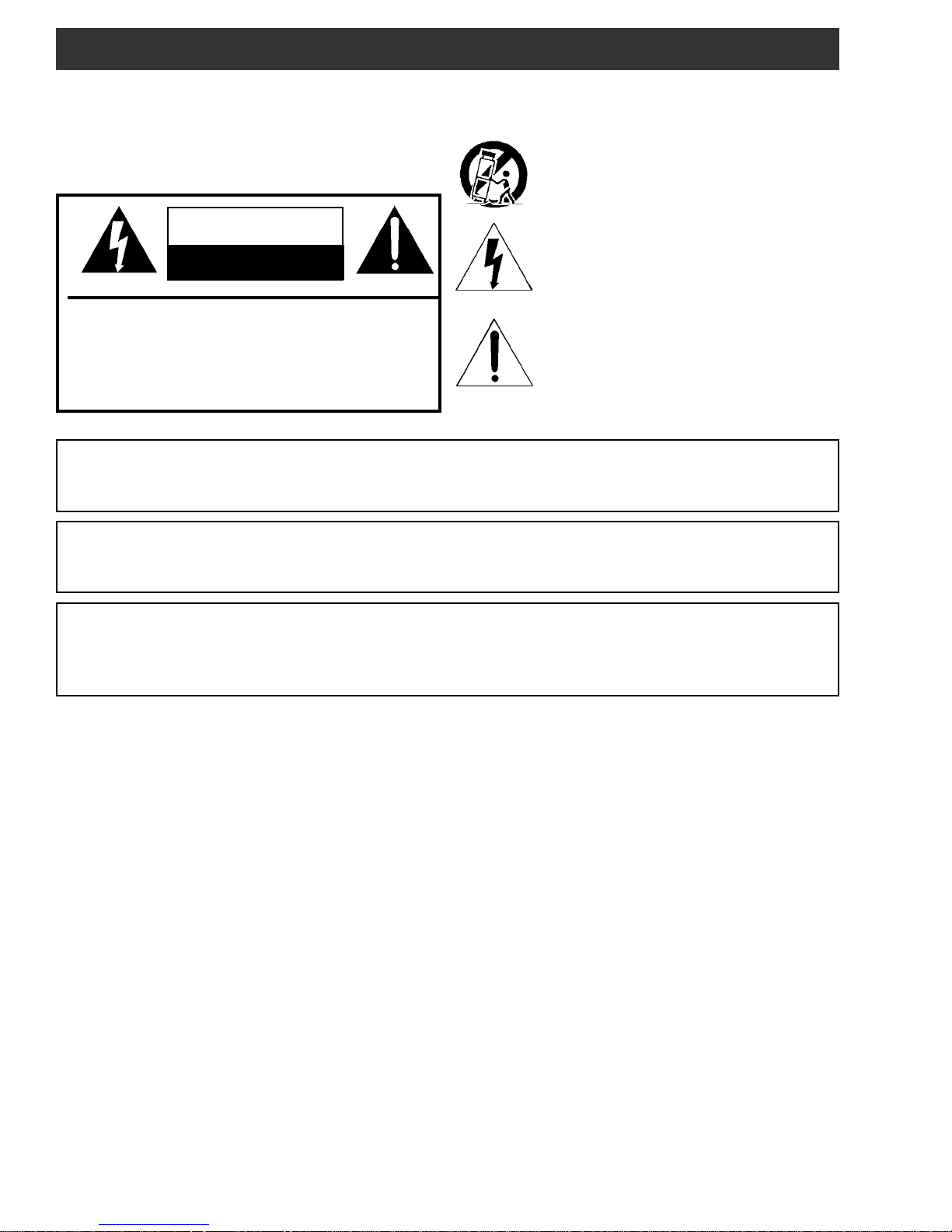
Caution Statements
WARNING: TO PREVENT FIRE OR
ELECTRICAL SHOCK DO NOT
EXPOSE TO RAIN OR MOISTURE
CAUTION
RISK OF ELECTRIC SHOCK
DO NOT OPEN
CAUTION: TO REDUCE THE RISK OF ELECTRIC
SHOCK,
DO NOT REMOVE COVER
NO USER-SERVICEABLE PARTS INSIDE
REFER SERVICING TO QUALIFIED PERSONNEL
WARNING:
CAUTION:
TO REDUCE THE RISK OF FIRE OR ELECTRIC SHOCK, DO NOT EXPOSE THIS
PRODUCT TO RAIN OR MOISTURE.
DO NOT OPEN THE CABINET, REFER SERVICING TO QUALIFIED PERSONNEL ONLY.
TO PREVENT ELECTRIC SHOCK, DO NOT USE THIS (POLARIZED) PLUG WITH AN
EXTENSION CORD RECEPTACLE OR OTHER OUTLET UNLESS THE BLADES CAN BE
FULLY INSERTED TO PREVENT BLADE EXPOSURE.
A product and cart combination should be moved with
care. Quick stops, excessive force and uneven
surfaces may cause the product and cart combination
to overturn.
The lightning flash with arrow head symbol, within an
equilateral triangle, is intended to alert the user to the
presence of uninsulated "dangerous voltage" within
the product's enclosure that may be of sufficient
magnitude to constitute a risk of electric shock to
persons.
The exclamation point within an equilateral triangle is
intended to alert the user to the presence of important
operating and maintenance (servicing) instructions in
the literature accompanying
the product.
ATTENTION:
POUR PREVENIR LES CHOCS ELECTRIQUES, NE PAS UTILISER CETTE FICHE
POLARISEE AVEC UN PROLONGATEUR, UNE PRISE DE COURANT OU UNE AUTRE
SORTIE DE COURANT, SAUF SI LES LAMES PEUVENT ETRE INSEREES A FOND
SANS EN LAISSER AUCUNE PARTIE A DECOUVERT.
Important Safety Instructions
3
1. Read Instructions—All the safety and operating instructions should be read
before the product is operated.
2. Retain Instructions—The safety and operating instructions should be
retained for future reference.
3. Heed Warnings—All warnings on the product and in the operating
instructions should be adhered to.
4. Follow Instructions—All operating and use instructions should be followed.
5. Cleaning—Unplug this product from the wall outlet before cleaning. Do not
use liquid cleaners or aerosol cleansers. Use a damp cloth for cleaning.
6. Attachments—Do not use attachments that are not recommended by the
product manufacturer as they may cause hazards.
7. Water and Moisture—Do not use this product near water—for example,
near a bathtub, wash bowl, kitchen sink or laundry tub; in a wet basement;
or near a swimming pool; and the like.
8. Accessories—Do not place this product on an unstable cart, stand, tripod,
bracket, or table. The product may fall, causing serious injury to a child or adult,
and serious damage to the product. Use only with a cart, stand, tripod, bracket,
or table recommended by the manufacturer, or sold with the product. Any
mounting of the product should follow the manufacturer's instructions, and
should use a mounting accessory recommended by the manufacturer.
9. A product and cart combination should be moved with care. Quick stops,
excessive force, and uneven surfaces may cause the product and cart
combination to overturn.
10. Ventilation—Slots and openings in the cabinet are provided for ventilation
and to ensure reliable operation of the product and to protect it from
overheating, and these openings must not be blocked or covered. The
openings should never be blocked by placing the product on a bed, sofa, rug,
or similar surface. This product should not be placed in a built-in installation
such as bookcase or rack unless proper ventilation is provided or the
manufacturer's instructions have been adhered to.
11. Power Sources—This product should be operated only from the type of
power source indicated on the marking label. If you are not sure of the type of
power supplied to your home, consult your product dealer or local power
company. For products intended to operate from battery power, or other
sources, refer to the operating instructions.
12. Grounding or Polarization—This product may be equipped with a
polarized alternating-current line plug (a plug having one blade wider than the
other). This plug will fit into the power outlet only one way. This is a safety
feature. If you are unable to insert the plug fully into the outlet, try reversing
the plug. If the plug should still fail to fit, contact your electrician to replace
your obsolete outlet. Do not defeat the safety purpose of the polarized plug.
Alternate Warnings—If this product is equipped with a three-wire groundingtype plug, a plug having a third (grounding) pin, the plug will only fit into a
grounding-type power outlet. This is a safety feature. If you are unable to insert
the plug into the outlet, contact your electrician to replace your obsolete outlet.
Do not defeat the safety purpose of the grounding-type plug.
12 a. Mise à la terre ou Polarisation—Cet appareil est équipé avec un cordon
d'alimentation à trois fils. Il est a brancher sur une prise ayant un connecteur
a la terre. Assurez-vous que la connection a la terre ne manque pas.
13. Power-Cord Protection—Power-supply cords should be routed so that
they are not likely to be walked on or pinched by items placed upon or against
them, paying particular attention to cords at plugs, convenience receptacles,
and the point where they exit from the product.
NOTE TO CATV SYSTEM INSTALLERS:
THIS REMINDER IS PROVIDED TO CALL THE
CATV SYSTEM INSTALLER'S ATTENTION TO
ARTICLE 820 - 40 OF THE NEC THAT
PROVIDES GUIDELINES FOR PROPER
GROUNDING AND, IN PARTICULAR, SPECIFIES THAT THE CABLE GROUND SHALL BE
CONNECTED TO THE GROUNDING SYSTEM
OF THE BUILDING, AS CLOSE TO THE POINT
OF CABLE ENTRY AS PRACTICAL.
14. Outdoor Antenna Grounding—If an outside antenna or cable system is
connected to the product, be sure the antenna or cable system is grounded so
as to provide some protection against voltage surges and built-up static
charges. Article 810 of the National Electrical Code, ANSI/NFPA 70, provides
information with regard to proper grounding of the mast and supporting
structure, grounding of the lead-in wire to an antenna discharge unit, size of
grounding conductors, location of antenna-discharge unit, connection to
grounding electrodes, and requirements for the grounding electrode.
See Figure A.
15. Lightning—For added protection for this product during a lightning storm,
or when it is left unattended and unused for long periods of time, unplug it from
the wall outlet and disconnect the antenna or cable system. This will prevent
damage to the product due to lightning and power-line surges.
16. Power Lines—An outside antenna system should not be located in the
vicinity of overhead power lines, other electric light or power circuits, where it
can fall into such power lines or circuits. When installing an outside antenna
system, extreme care should be taken to keep from touching such power lines
or circuits as contact with them may be fatal.
17. Overloading—Do not overload wall outlets, extension cords, or integral
convenience receptacles as this can result in a risk of fire or electric shock.
18. Object and Liquid Entry—Never push objects of any kind into this product
through openings as they may touch dangerous voltage points or short-out
parts that could result in a fire or electric shock. Never spill liquid of any kind
on the product.
19. Servicing—Do not attempt to service this product yourself as opening
or removing covers may expose you to dangerous voltage or other hazards.
Refer all servicing to qualified service personnel.
20. Damage Requiring Service—Unplug this product from the wall outlet and
refer servicing to qualified service personnel under the following conditions:
a. When the power-supply cord or plug is damaged,
b. If liquid has been spilled, or objects have fallen into the product,
c. If the product has been exposed to rain or water,
d. If the product does not operate normally by following the operating
instructions. Adjust only those controls that are covered by the operating
instructions as an improper adjustment of other controls may result in damage
and will often require extensive work by a qualified technician to restore the
product to its normal operation,
e. If the product has been dropped or damaged in any way, and
f. When the product exhibits a distinct change in performance—this indicates
a need for service.
21. Replacement Parts—When replacement parts are required, be sure the
service technician has used replacement parts specified by the manufacturer
or have the same characteristics as the original part. Unauthorized substitutes
may result in fire, electric shock or other hazards.
22. Safety Check—Upon completion of any service or repairs to this product,
ask the service technician to perform safety checks to determine that the
product is in proper operating condition.
23. Wall or Ceiling Mounting—The product should be mounted to a wall or
ceiling only as recommended by the manufacturer.
24. Heat—The product should be situated away from heat sources such as
radiators, heat registers, stoves, or other products (including amplifiers) that
produce heat.
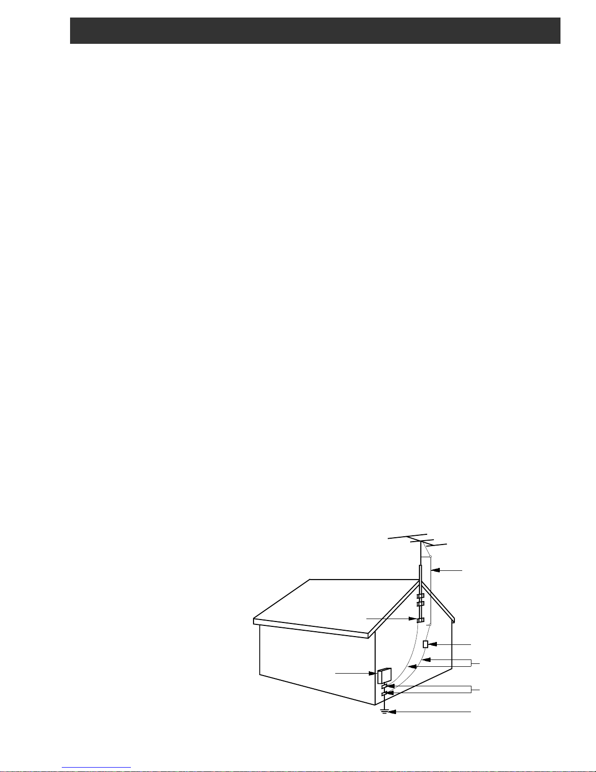
Example of antenna grounding as per National Electrical Code, ANSI/NFPA 70
Figure A
ANTENNA
LEAD IN
WIRE
GROUND CLAMP
ELECTRIC
SERVICE
EQUIPMENT
NEC - NATIONAL ELECTRIC CODE
ANTENNA
DISCHARGE UNIT
(NEC SECTION 810-20)
GROUNDING CONDUCTORS
(NEC SECTION 810-21)
GROUND CLAMPS
POWER SERVICE GROUNDING
ELECTRODE SYSTEM
(NEC ART 250, PART H)

4 Table of Contents / Specifications
TABLE OF CONTENTS
2 Caution Statements
3 Important Safety Instructions
4 Table of Contents / Specifications
5 Purpose
6 General Description & Installation
7 Additional System Components
8 Front Panel Controls & Connections
9 Rear Panel Controls & Connections
SRR60 RECEIVER
IR Microphone Channels:
Inputs:
AUX Input, RCA jacks, front:
AUX Input, 3.5mm jack, front:
AUX Input, 3.5mm jack, rear:
3 Band Equalizers:
MIC Channel A:
MIC Channel B:
AUX1, AUX2 combined:
Volume Controls, front panel:
MIC, Channel A:
MIC, Channel B:
AUX 1:
AUX 2:
AUX 3:
MASTER VOLUME (speakers):
Outputs:
Speaker, rear panel terminals:
Line level AUX, front panel:
Line level AUX, rear panel:
Volume Controls,
recessed screwdriver set:
Trim for each speaker output:
Trim for each AUX Line output:
Amplifier Output Power:
Total Harmonic Distortion (THD):
Output Impedance, speaker outputs:
Receiver Frequency Response:
Remote IR pickup sensor inputs:
Speaker Muting:
Safety :
5 total
2 (CH A and CH B)
1
1
1
3 sets
1
1
1
6
1
1
1
1
1
1
6
4 sets
1
1
6
4
2
60 W maximum @ <10%
THD (15W nominal per
speaker output)
< .5 %, 1 kHz, .01 to
10 W/ CH into 8 ohms
8 ohms, nominal
20 Hz to 20 kHz
3 (1, 2, or 3 may be
used depending on
room size and dimensions.)
Contact Closure and
Audio Sensing Inputs
Safety certified to
ANSI/UL 60065, 7th ed.
dated 6/30/04, rev
11/20/06
CAN/CSA-C22.2 No.
60065:03 (2006)
10 BP60 Belt Pack Controls & Connections
11 HHM60 Microphone Controls & Connections
12 Battery installation & Charging
13 Daily Operation
16 General Usage Tips
17 Troubleshooting Guide
18 Service / If you Need To Call For Help
19 Warranty
SPECIFICATIONS for SRR60 and related system components
SRR60 RECEIVER (Continued)
Receiver Power Requirement:
BP60 BELT P ACK with EM60LA VALIERE MIC
Channels:
IR Subcarrier Frequencies:
Battery Current:
Battery Type:
(2 used)
Charging Time:
Microphone Gain:
HHM60 HAND HELD MICROPHONE
Channels:
IR Subcarrier Frequencies:
Battery Current:
Battery Type:
(2 used)
Charging Time:
Microphone Gain:
120 VAC, +/- 20 %
50/60 Hz / 150 W Max.
75 W nominal @ full output /
8 ohm speakers.
150 W during fault condition
such as shorted outputs.
2 user selectable
CH 1 - 2.06 MHz
CH 2 - 2.56 MHz
mA low (LO): 100 mA
mA high (HI): 160 mA
AA, Ni-MH rechargeable,
minimum of 2000 mAH
Approx 12 - 14 hours to
charge depleted 2100 mAH
cells using supplied
charger.
User Adjustable - access
inside battery compartment
2 user selectable
CH 1 - 2.06 MHz
CH 2 - 2.56 MHz
mA low (LO) - 230 mA
mA high (HI) - 350 mA
AA, Ni-MH rechargeable,
minimum of 2000 mAH
Approx 12 - 14 hours to charge
depleted 2100 mAH cells using
supplied charger.
Set by factory
FCC:
Part 15 B
Specifications subject to change without notice or obligation.
Purpose 5
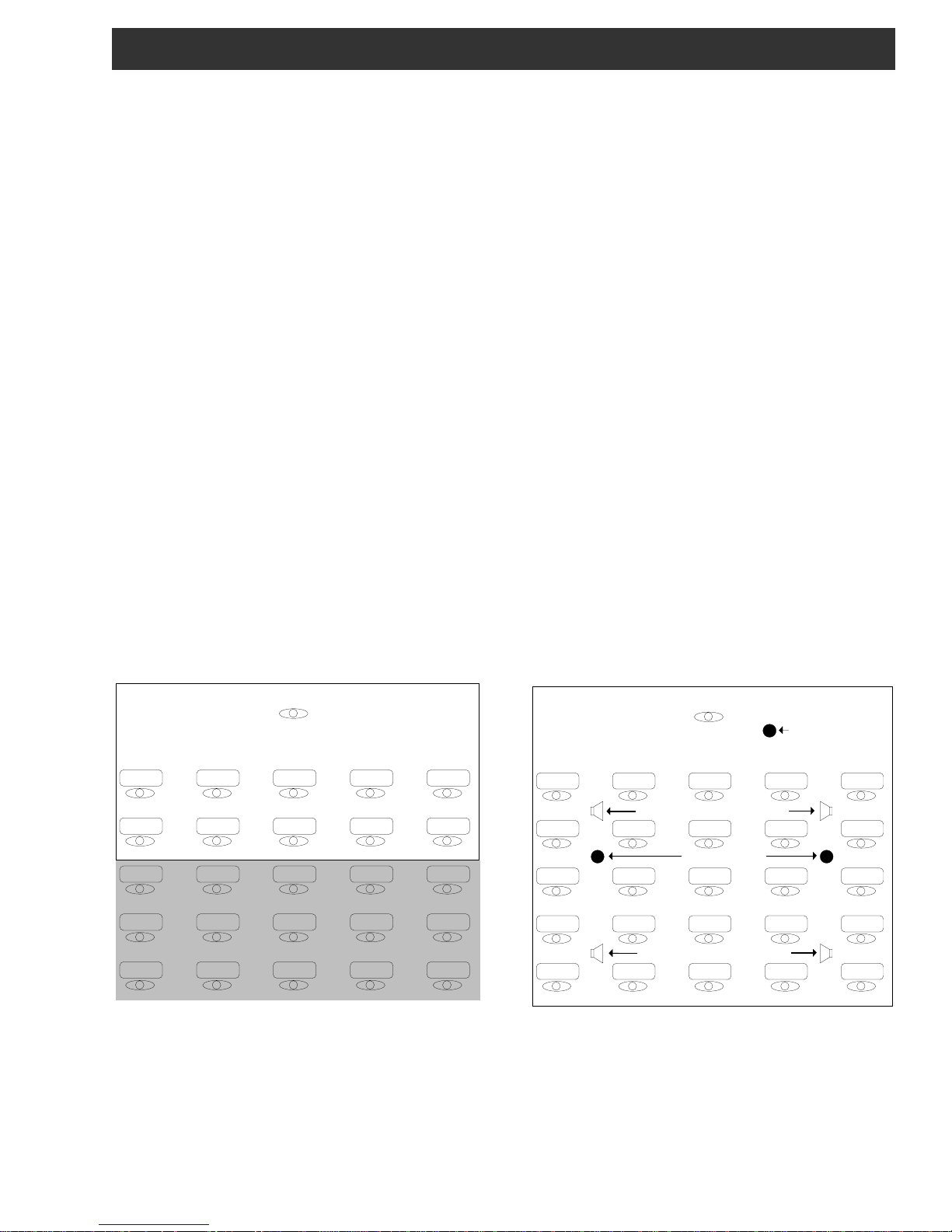
PURPOSE
In a typical classroom environment, a teacher
in front of the room lectures to a room filled with 30
or 40 students. Those students in the first few rows
can easily hear what the teacher is saying, but those
further back in the classroom frequently find that
hearing the teacher over the ambient noise of the
room can be considerably more difficult. This
frequently leads to lack of comprehension, inattention, disorder, teacher fatigue, and a generally less
than ideal learning environment.
The R. L. Drake SRR60 Sound Reinforcement
Receiver and associated system microphones, IR
sensors, and speakers, successfully addresses this
problem by supplying the teacher with a lavaliere
microphone which transmits his or her voice by
infrared (IR) signals to sensors placed at strategic
locations around the classroom. These sensors pick
up the infrared signals and feed them to the SRR60
Receiver which, in turn detects and amplifies them
and feeds the teacher’s voice to loudspeakers placed
in such a way as to provide equal sound volume to all
points in the room. In this way, all students in the
room have equal access to what
the teacher is saying, which greatly improves
attentiveness and comprehension for those students
farthest from the teacher, which in turn results in less
teacher stress.
A hand held IR microphone is typically used
with the system and can be passed to students who
are responding to questions, or are otherwise
contributing in class discussions. The SRR60
Receiver also accepts external audio inputs from
various audio-visual aids such as CD and DVD
players, VCRs, TVs and computers.
Two audio outputs are provided for feeding
audio recorders, or assistive listening transmitters to
accommodate those with impaired hearing.
While the SRR60 was designed with classrooms
in mind, it will provide just as great a benefit when
used in any similar environment such as meeting
rooms, large conference rooms, churches, etc.
TYPICAL CLASSROOM
TEACHER
STUDENTS
GOOD LISTENING AREA
POOR LISTENING AREA
CLASSROOM WITH SRR60 SYSTEM
TEACHER
Infrared sensor
STUDENTS
Ceiling mounted loudspeakers
Infrared Sensors
GOOD LISTENING AREA
Ceiling mounted loudspeakers
6 General Description & Installation
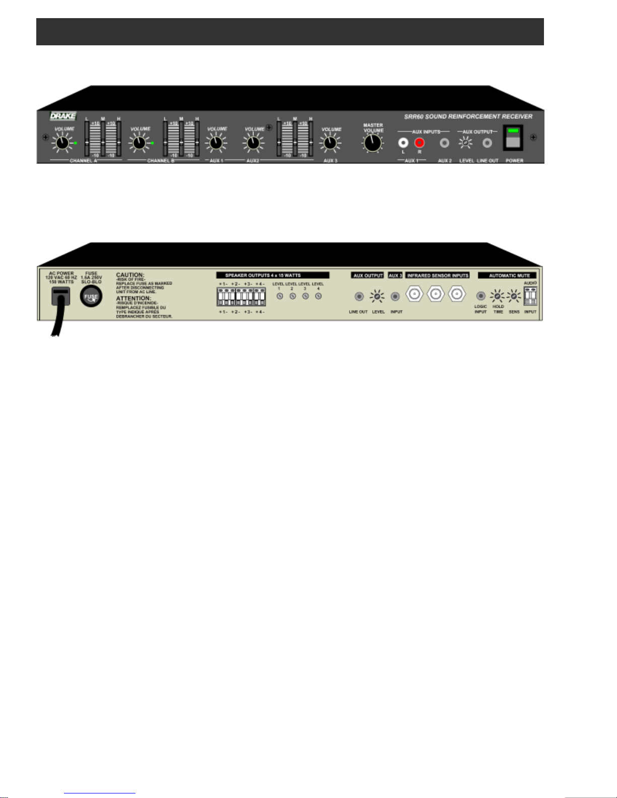
SRR60 Sound Reinforcement Receiver Front View
SRR60 Sound Reinforcement Receiver Rear View
GENERAL DESCRIPTION
The R.L. Drake model SRR60 is a professional
quality Sound Reinforcement Receiver which
accepts audio modulated infrared (IR) signals from
up to two separate IR transmitters, such as hand
held and/or lavaliere microphones. The SRR60 can
accommodate up to three external infrared sensors,
statically placed throughout a classroom or other
similar facility, which detect the transmitted IR
microphone signals. The SRR60 demodulates these
signals, provides audio shaping by means of two,
three-band equalizers, one for each IR transmitter,
and provides up to 15 watts of audio output to each
of four external speakers placed throughout the
classroom or other facility.
The SSR60 can also accept up to three
additional audio sources for connection to audio/
visual equipment such as CD or cassette players,
VCRs, DVD players, TVs, computers, etc. An
additional three-band equalizer is provided for audio
shaping of two of the three external audio sources.
Two AUX audio outputs are also provided for
connection to assistive listening transmitters or to
audio recording devices.
When connected to an external public address
system, the SRR60 can be automatically or manually muted whenever this public address system is
active.
INSTALLATION
It is recommended that the SRR60 Sound
Reinforcement Receiver be installed by a qualified
installer. Once installed, this manual covers the
required set up and also provides instructions for the
day to day use of the system.
 Loading...