

DRAKE SCT3860 Instruction Manual

SCT3860 Transcoder System
Instruction Manual
© Copyright 2008 R.L. Drake Company P/N: 3852383E-01-2008
TM is a registered trademark of the R.L. Drake Company
2
Caution Statements
WARNING: TO PREVENT FIRE OR
ELECTRICAL SHOCK DO NOT
EXPOSE TO RAIN OR MOISTURE
CAUTION
RISK OF ELECTRIC SHOCK
DO NOT OPEN
CAUTION: TO REDUCE THE RISK OF ELECTRIC
SHOCK,
DO NOT REMOVE COVER
NO USER-SERVICEABLE PARTS INSIDE
REFER SERVICING TO QUALIFIED PERSONNEL
WARNING:
CAUTION:
TO REDUCE THE RISK OF FIRE OR ELECTRIC SHOCK, DO NOT EXPOSE THIS PRODUCT
TO RAIN OR MOISTURE.
DO NOT OPEN THE CABINET, REFER SERVICING TO QUALIFIED PERSONNEL ONLY.
TO PREVENT ELECTRIC SHOCK, DO NOT USE THIS (POLARIZED) PLUG WITH AN EXTENSION
CORD RECEPTACLE OR OTHER OUTLET UNLESS THE BLADES CAN BE FULLY INSERTED TO
PREVENT BLADE EXPOSURE.
A product and cart combination should be moved
with care. Quick stops, excessive force and
uneven surfaces may cause the product and cart
combination to overturn.
The lightning flash with arrow head symbol, within
an equilateral triangle, is intended to alert the user
to the presence of uninsulated "dangerous voltage"
within the product's enclosure that may be of
sufficient magnitude to constitute a risk of electric
shock to persons.
The exclamation point within an equilateral triangle
is intended to alert the user to the presence of
important operating and maintenance (servicing)
instructions in the literature accompanying
the product.
ATTENTION:
POUR PREVENIR LES CHOCS ELECTRIQUES, NE PAS UTILISER CETTE FICHE POLARISEE
AVEC UN PROLONGATEUR, UNE PRISE DE COURANT OU UNE AUTRE SORTIE DE
COURANT, SAUF SI LES LAMES PEUVENT ETRE INSEREES A FOND SANS EN LAISSER
AUCUNE PARTIE A DECOUVERT.
Important Safety Instructions 3
1. Read Instructions—All the safety and operating instructions should be read
before the product is operated.
2. Retain Instructions—The safety and operating instructions should be
retained for future reference.
3. Heed Warnings—All warnings on the product and in the operating
instructions should be adhered to.
4. Follow Instructions—All operating and use instructions should be followed.
5. Cleaning—Unplug this product from the wall outlet before cleaning. Do not
use liquid cleaners or aerosol cleansers. Use a damp cloth for cleaning.
6. Attachments—Do not use attachments that are not recommended by the
product manufacturer as they may cause hazards.
7. Water and Moisture—Do not use this product near water—for example,
near a bathtub, wash bowl, kitchen sink or laundry tub; in a wet basement;
or near a swimming pool; and the like.
8. Accessories—Do not place this product on an unstable cart, stand, tripod,
bracket, or table. The product may fall, causing serious injury to a child or adult,
and serious damage to the product. Use only with a cart, stand, tripod, bracket,
or table recommended by the manufacturer, or sold with the product. Any
mounting of the product should follow the manufacturer's instructions, and
should use a mounting accessory recommended by the manufacturer.
9. A product and cart combination should be moved with care. Quick stops,
excessive force, and uneven surfaces may cause the product and cart
combination to overturn.
10. Ventilation—Slots and openings in the cabinet are provided for ventilation
and to ensure reliable operation of the product and to protect it from
overheating, and these openings must not be blocked or covered. The
openings should never be blocked by placing the product on a bed, sofa, rug,
or similar surface. This product should not be placed in a built-in installation
such as bookcase or rack unless proper ventilation is provided or the
manufacturer's instructions have been adhered to.
11. Power Sources—This product should be operated only from the type of
power source indicated on the marking label. If you are not sure of the type of
power supplied to your home, consult your product dealer or local power
company. For products intended to operate from battery power, or other
sources, refer to the operating instructions.
12. Grounding or Polarization—This product may be equipped with a
polarized alternating-current line plug (a plug having one blade wider than the
other). This plug will fit into the power outlet only one way. This is a safety
feature. If you are unable to insert the plug fully into the outlet, try reversing
the plug. If the plug should still fail to fit, contact your electrician to replace
your obsolete outlet. Do not defeat the safety purpose of the polarized plug.
Alternate Warnings—If this product is equipped with a three-wire groundingtype plug, a plug having a third (grounding) pin, the plug will only fit into a
grounding-type power outlet. This is a safety feature. If you are unable to insert
the plug into the outlet, contact your electrician to replace your obsolete outlet.
Do not defeat the safety purpose of the grounding-type plug.
12 a. Mise à la terre ou Polarisation—Cet appareil est équipé avec un cordon
d'alimentation à trois fils. Il est a brancher sur une prise ayant un connecteur a
la terre. Assurez-vous que la connection a la terre ne manque pas.
13. Power-Cord Protection—Power-supply cords should be routed so that
they are not likely to be walked on or pinched by items placed upon or against
them, paying particular attention to cords at plugs, convenience receptacles,
and the point where they exit from the product.
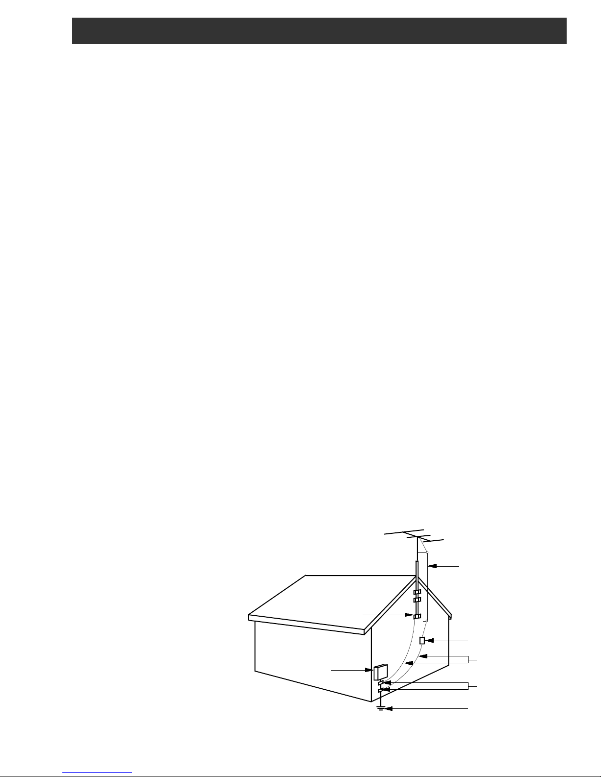
14. Outdoor Antenna Grounding—If an outside antenna or cable system is
connected to the product, be sure the antenna or cable system is grounded so
as to provide some protection against voltage surges and built-up static
charges. Article 810 of the National Electrical Code, ANSI/NFPA 70, provides
information with regard to proper grounding of the mast and supporting
structure, grounding of the lead-in wire to an antenna discharge unit, size of
grounding conductors, location of antenna-discharge unit, connection to
grounding electrodes, and requirements for the grounding electrode.
See Figure A.
15. Lightning—For added protection for this product during a lightning storm,
or when it is left unattended and unused for long periods of time, unplug it from
the wall outlet and disconnect the antenna or cable system. This will prevent
damage to the product due to lightning and power-line surges.
16. Power Lines—An outside antenna system should not be located in the
vicinity of overhead power lines, other electric light or power circuits, where it
can fall into such power lines or circuits. When installing an outside antenna
system, extreme care should be taken to keep from touching such power lines
or circuits as contact with them may be fatal.
17. Overloading—Do not overload wall outlets, extension cords, or integral
convenience receptacles as this can result in a risk of fire or electric shock.
18. Object and Liquid Entry—Never push objects of any kind into this product
through openings as they may touch dangerous voltage points or short-out
parts that could result in a fire or electric shock. Never spill liquid of any kind
on the product.
19. Servicing—Do not attempt to service this product yourself as opening
or removing covers may expose you to dangerous voltage or other hazards.
Refer all servicing to qualified service personnel.
20. Damage Requiring Service—Unplug this product from the wall outlet and
refer servicing to qualified service personnel under the following conditions:
a. When the power-supply cord or plug is damaged,
b. If liquid has been spilled, or objects have fallen into the product,
c. If the product has been exposed to rain or water,
d. If the product does not operate normally by following the operating
instructions. Adjust only those controls that are covered by the operating
instructions as an improper adjustment of other controls may result in damage
and will often require extensive work by a qualified technician to restore the
product to its normal operation,
e. If the product has been dropped or damaged in any way, and
f. When the product exhibits a distinct change in performance—this indicates
a need for service.
21. Replacement Parts—When replacement parts are required, be sure the
service technician has used replacement parts specified by the manufacturer
or have the same characteristics as the original part. Unauthorized substitutes
may result in fire, electric shock or other hazards.
22. Safety Check—Upon completion of any service or repairs to this product,
ask the service technician to perform safety checks to determine that the
product is in proper operating condition.
23. Wall or Ceiling Mounting—The product should be mounted to a wall or
ceiling only as recommended by the manufacturer.
24. Heat—The product should be situated away from heat sources such as
radiators, heat registers, stoves, or other products (including amplifiers) that
produce heat.
NOTE TO CATV SYSTEM INSTALLERS:
THIS REMINDER IS PROVIDED TO CALL THE
CATV SYSTEM INSTALLER'S ATTENTION TO
ARTICLE 820 - 40 OF THE NEC THAT
PROVIDES GUIDELINES FOR PROPER
GROUNDING AND, IN PARTICULAR, SPECIFIES THAT THE CABLE GROUND SHALL BE
CONNECTED TO THE GROUNDING
SYSTEM OF THE BUILDING, AS CLOSE TO
THE POINT OF CABLE ENTRY AS PRACTICAL.
Example of antenna grounding as per National Electrical Code, ANSI/NFPA 70
GROUND CLAMP
ELECTRIC
SERVICE
EQUIPMENT
NEC - NATIONAL ELECTRIC CODE
Figure A
ANTENNA
LEAD IN
WIRE
ANTENNA
DISCHARGE UNIT
(NEC SECTION 810-20)
GROUNDING CONDUCTORS
(NEC SECTION 810-21)
GROUND CLAMPS
POWER SERVICE GROUNDING
ELECTRODE SYSTEM
(NEC ART 250, PART H)

4 Table of Contents / Specifications
TABLE OF CONTENTS
2 Caution Statements
3 Important Safety Instructions
4 Table of Contents / Specifications
5 General Description / Installation and Mounting
6 Controls and Connections
7 LNB Input / Setup and Programming
8 Setup and Programming (continued)
9 Additional Features
10 Additional Features (continued)
11 CATV Channel Frequencies Tables
12 Broadcast Channel Frequency Tables
13 Service / If You Need To Call For Help
14 Warranty
SPECIFICATIONS
SATELLITE INPUT
Frequency Range:
Tuning Increment:
Acquisition Range:
Input Level:
Input Impedance:
I/Q Phase Imbalance:
I/Q Amplitude Imbalance:
Mode:
FEC:
VITERBI Autoscan:
Turbo QPSK modes:
Turbo 8PSK modes:
Input Data Rate:
QAM OUTPUT
Output Impedance:
Output Level:
Display Error:
Level Adjustment Increment:
Frequency Range:
Frequency Plan:
Broadband Spurious:
Broadband Noise:
Phase Noise:
Frequency Stability:
QAM I/Q Phase Error:
Channel Amplitude Error:
Carrier Suppression:
MER:
Mode:
Symbol Rate:
FEC:
950 MHz to 2150 MHz.
500 kHz.
±5.0 MHz minimum.
-25 dBm to -70 dBm.
75 Ohms, return loss of 10 dB minimum.
<1 Degree.
<1dB.
QPSK, 8PSK.
DCII, DVB, advanced Turbo modes
1/2, 2/3, 3/4, 5/6, 6/7, 7/8 - DVB
5/11, 1/2, 3/5, 2/3, 3/4, 4/5, 5/6, 7/8 - DCII
1/2, 3/4, 2/3, 5/6, 7/8
2/3, 5/6, 8/9, 3/4, 4/5
2 Mbaud to 30 Mbaud.
75 Ohms, return loss of 10 dB minimum.
+ 25 to +40 dBmV, displayed.
± 2 dB maximum.
1 dB, nominal.
54 MHz to 864 MHz.
Standard, IRC, or HRC CATV channels
or off-air broadcast channels.
-60 dB, 5 MHz to 900 MHz.
-75 dBc, 6 MHz bandwidth.
-103 dBc/Hz @ 10 kHz offset.
± 5 kHz.
<1 degree.
<1 dB.
45 dB.
>40 dB, with blind equalizer.
16, 32, 64, 128, 256, 512, 1024 QAM.
1 Mbaud to 7 Mbaud.
ITU-T J.83 Annex A or Annex B.
RS232 CONTROL
Data Link:
RS232 Input:
RS232 Output:
GENERAL
Operating Temperature Range:
Size:
Weight:
Power Requirement:
4800 baud interface to PS151 via power
supply cable.
DB-9 connector on PS151 for connection
to modem or PC.
DB-9 connector on PS151 for connection
to additional transcoders.
00 C to +500 C, ambient.
1.1" W x 3.4" H x 13.25" D.
1 lb. 6 oz.
All voltages are provided by the Drake
model PS151 power supply. PS151
power requirement: 90 to 260 VAC / 150
W, maximum w. 10 transcoders powered.
Specifications subject to change without notice or obligation.
General Description / Installation and Mounting 5
DRAKE TRANSCODER SYSTEM
L BAND INPUTS
GENERAL DESCRIPTION
The R.L. Drake model SCT3860 is a
professional quality, modular, digital headend component
providing QPSK or 8PSK input to QAM transmodulation
and RF upconversion functions in a single module. Up to
ten SCT3860 modules and a power supply module can
be accommodated in the RMT150 rack mounting tray,
occupying only a 2 unit (3.5”) high rack space. The
SCT3860 can transcode DigiCipher II or DVB digital
satellite signals, included those with advanced turbo
satellite FEC modes, outputting QAM modulation.
The SCT3860 accepts L band RF inputs between 950
and 2150 MHz from the LNB at the satellite dish. The
transcoder demodulates the selected satellite QPSK or
8PSK signal. The forward error correction (FEC) imbedded in the data stream is used to help retrieve an error
free digital transport stream containing the desired digital
programming multiplex.
ID 1.1
12.45 dB
UNIT
ENTER
SELECT
The transcoder then applies cable environment FEC to
this stream and remodulates using QAM modulation that
occupies a nominal 6 MHz wide cable channel slot. QAM
modes up through 1024QAM are supported.
The RF upconverter then upconverts the IF QAM signal to
the selected output channel - any standard EIA, IRC, or
HRC CATV channel or a broadcast off-air channel
frequency in the range of 54 to 860 MHz.
Bandpass flatness and phase noise are very closely
controlled in the SCT3860 to insure a high MER and S/N
ratio of the output signal. This insures that the transcoder
will not introduce a source of errors into the distribution
process. Because the MPEG2 transport stream information is not modified by the transcoder, all encryption,
authorization, and program guide information is passed
on to the CATV set top box, unchanged.
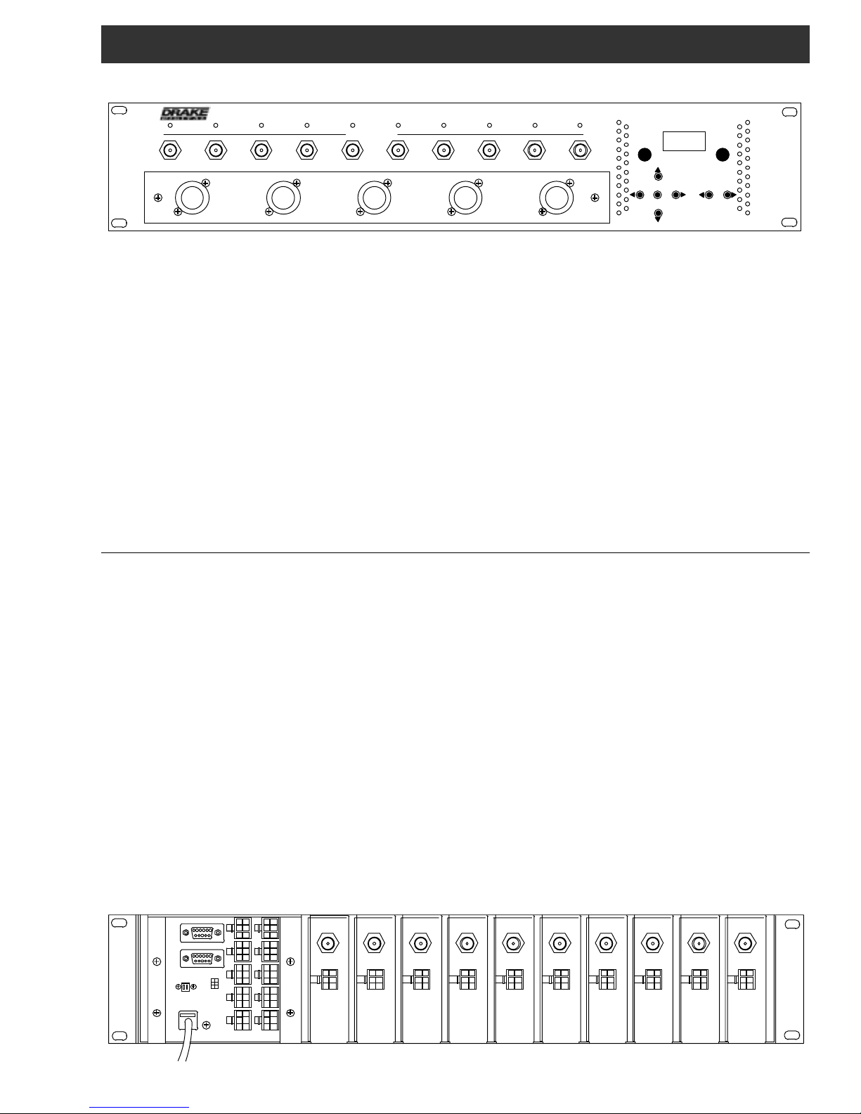
INSTALLATION AND MOUNTING
Install the SCT3860 transcoders in the RMT150 rack
mounting frame. Slide each module into the tray so that
the "F" connector extends though the front panel hole, the
LED is properly aligned behind its front panel hole, and
the hook shaped projection on the bottom of the module
engages the rear of the mounting tray. Secure the
module with the supplied standard 1/2 inch "F" connector
mounting nut and nylon washer.
Similarly, mount the PS151 power supply in the RMT150
tray, making sure that the LCD display and control buttons
line up with their corresponding holes in the front panel,
and that the hook shaped projections on the rear of the
unit engage the rear of the mounting tray. Secure the
unit in place, with the supplied Philips head black
screws, from the front panel. Connect each SCT3860 to
the PS151 with the cable included with the SCT3860.
Each SCT3860 can connect to any one of the ten sockets
on the power supply. However, to minimize confusion, it
is suggested that the left most unit (as viewed from the
front panel) be connected to power supply socket
number 1, the second from the left to number 2, etc.
RS232 OUT
RS232 IN
FAN POWER
100 - 240 VAC
47 - 63 HZ, 125 W
12
34
56
+12
+3
+5
GND
TX
RX
78
910
RF OUTPUT
POWER
RF OUTPUT
POWER
RF OUTPUT
POWER
Connect the LNB signal to each SCT3860 module at the
front panel connector. Connect each SCT3860 RF output
"F" connector on the rear of the unit to the output combiner. The Drake model LBS2250 is a combination LNB
L band multiswitch/amplified splitter in addition to a CATV
output combiner. It provides these functions in only 1 RU
of rack space. Also, plug the cable from the front panel
fan module into the FAN POWER receptacle on the rear
of the power supply. Plug the line cord from the PS151
into the AC power source. SCT3860s can be mixed with
SCT1860s, SCT2860s, or SCT4860s and one PS151.
When installing the RMT150 tray of transcoders, it is not
necessary to leave a vertical airspace between the
transcoder tray and other equipment unless that other
equipment specifies that a space should be left open.
The air flow through the transcoders and power supply
has been designed to allow immediate adjacent
mounting of multiple RMT150 trays with SCT3860
transcoders and PS151 power supplies installed. Of
course, air spaces may be left in between RMT150s if
desired.
RF OUTPUT
POWER
RF OUTPUT
POWER
RF OUTPUT
POWER
RF OUTPUT
POWER
RF OUTPUT
POWER
RF OUTPUT
POWER
RF OUTPUT
POWER
 Loading...