

Page 1
®
RMM12 Rac
k Mount 1
The RMM12 Ra ck Mount suppo rts a single Dra ke P ower
Supply and up to (12) modular Audio/Video modulators to
congure a professional quality, modular, headend system,
which optimizes rack spac e.
Identify the following items shipped with this kit of rack mount
assem bly and cable assem bly:
(1) RMM12 Ra ck Mount chassi s .
(1) Wir e, ground bonding chassis to power supply
(1) C able Ass embly, 37-pin D conne ctor (mal e) to (1 2) fan-out
3-Ckt connectors (female)
(2) End Cap s , Bla ck
Ins tall ation :
Adequate ventilation is very important in multichannel
installations. Ra ck units should be spaced apa rt by at least
one panel height wherever pos si ble, and so me air moveme nt
is advis a ble in enclos ed rack cabinets. E xces sive heat will
ten the life of components and individual module(s).
shor
Power supply performance will also be degraded without
proper cooling.
If desired, the supplied black end caps can be installed over
the mounting ears of the RMM12 and secured by the rack
support s crews.
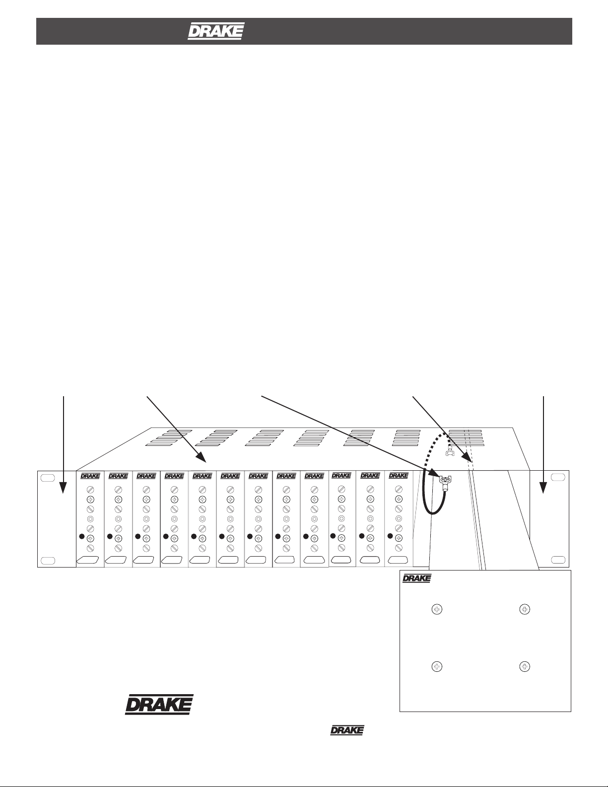
Locate the Power Supply (sold sepa rately) . P rior to sliding the
power supply into the right-hand side top a nd bottom s lide rails
of the RMM12, loosen the #6-32 scr ew located on the top
surface of the power supply. P osition the free end of the
ground wire lug (other end of wire fastened to RMM12) under
the #6-32 scr ew, and tighten the scr ew to secure the ground
wire. Slide the power supply into the RMM12.
If necessa ry, use the following steps to remove the Drake
Power Supply from the rack:
1) Rem ove the
module immediately adjacent to the Drake
Power Suppl y. Be aware that the module power ca ble will
become disconnected from the rear when the module is
remove d.
2) Now grasp the edge of the Drake Power Supply front panel
and remove the unit from rack.
3) R econnect the module power cable then repla ce the
adjacent module as required.
BL ACK END CAP
(DEC O RATI VE )
AU DIO
VIDEO
PWR
A / V
#
CH
SECURE LUG (G R OUND
BONDING WIRE) UNDER
RM M12
AU DIO
VIDEO
AU DIO
VIDEO
PWR
PWR
A / V
A / V
#
CH
RF
RF
AU DIO
VIDEO
PWR
A / V
#
#
CH
RF
CH
RF
#6- 32 S C R E W HEA D.
AU DIO
AU DIO
VIDEO
VIDEO
PWR
PWR
A / V
#
CH
A / V
#
CH
RF
RF
AU DIO
VIDEO
PWR
A / V
#
CH
RF
FIGURE 1 - Front Vi ew of Rack Mount System with
Power Supply
SLIDE RAIL (INTERNAL
TO R ACK CHASSI S , TOP
AND B OTTOM).
AU DIO
VIDEO
AU DIO
VIDEO
PWR
PWR
A / V
A / V
#
#
CH
CH
RF
RF
AU DIO
VIDEO
PWR
A / V
#
#
CH
CH
RF
AU DIO
VIDEO
AU DIO
VIDEO
PWR
PWR
A / V
A / V
#
CH
RF
RF
BL ACK END CAP
(DEC O RATIVE)
P OW E R S U PP LY
R .L. DRAK E HOLDINGS LLC
®
710 Pleasant Vally Drive
CUSTOMER SERVICE AND PARTS TELEPHONE: +1 (937) 746-6990
Springboro, Ohio 45066
FAX: +1 (937) 806-1510
http://www.rldrake.com
® is a registere d trademark of the R . L. Dra ke Holdings LLC
© Copyright 20 13 R .L. Dr ake Holdings LLC
P/N: 651231900A
Printed in Taiwan.
Page 2
2 RMM12 Rack Mount, continued
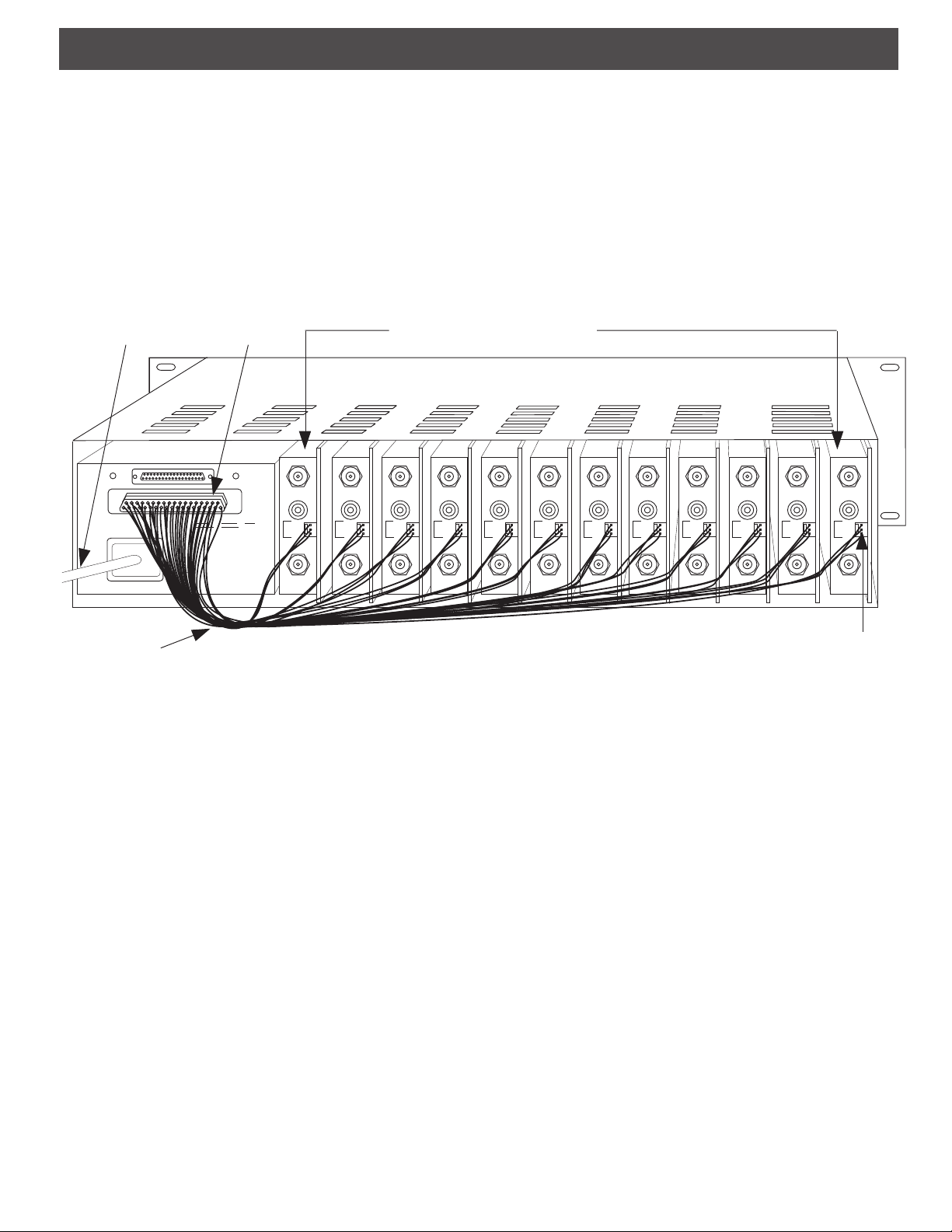
With the Drake Power Supply installed in the RMM12, connect
the 37-pin D connector to the mating connector at the rear of
the Drake Power Supply. Slide individual modules (maximum
of 12 units) into the desired rack locations. Connect one 3-Ckt
connector to the rear panel power input connector of each
installed module. Connect the shorter 3-Ckt cables to the
modules that are located closer to the power supply, and
AC POWER
CORD
20
1
37-PIN
CONNECTOR
37
19
+12VDC
+5VDC
(3A Max):
(3A Max):
Pins 2, 3, 5,
Pins 1, 4, 7,
6, 8, 9,11,
12, 15, 18,
13, 14, 16,
21, 24, 27,
17, 19.
30, 33, 36.
100-240 V
~
50/60 Hz
75 WATTS
VIDEO INPUT VIDEO INPUT VIDEO INPUT VIDEO INPUT VIDEO INPUT VIDEO INPUT VIDEO INPUT VIDEO INPUT VIDEO INPUT VIDEO INPUT VIDEO INPUT VIDEO INPUT
AUDIO INPUT AUDIO INPUT AUDIO INPUT AUDIO INPUT AUDIO INPUT AUDIO INPUT AUDIO INPUT AUDIO INPUT AUDIO INPUT AUDIO INPUT AUDIO INPUT AUDIO INPUT
GND:
Pins 10, 20,
22, 23, 25,
26, 28, 29,
31, 32, 34,
35, 37.
+5V
+12V
GND
DC INPUT DC INPUT DC INPUT DC INPUT DC INPUT DC INPUT DC INPUT DC INPUT DC INPUT DC INPUT DC INPUT DC INPUT
RF OUT RF OUT RF OUT RF OUT RF OUT RF OUT RF OUT RF OUT RF OUT RF OUT RF OUT RF OUT
+5V
+12V
GND
AUDIO/VIDEO MODULATORS
(REAR PANEL VIEW)
+5V
+12V
GND
longer cables to the modules located farther from the power
supply. Avoid stretching the cables or routing them where
damage to the cable is likely.
After the desired modules are installed into the RMM12 and
the RMM12 is secured in the rack, connect the power supply
to a source of AC power.
+5V
+12V
GND
+5V
+12V
GND
+5V
+12V
GND
+5V
+12V
GND
+5V
+12V
GND
+5V
+12V
GND
+5V
+12V
GND
+5V
+12V
GND
+5V
+12V
GND
DC POWER
CABLES
FIGURE 2 - Rear View of System with
12 Audio/Video Modulators.
3-PIN MALE
CONNECTOR
(TYPICAL)
 Loading...