

DRAKE SCT, R.L. DIGITAL HEADEND CONTROL PROGRAM Instruction Manual

INTRODUCTION
The SCT series of transcoders and also the DQT861 and MQM861 products provide for
remote monitoring and control. This is accomplished via a RS232 data connection between the
controlling PC and the units. The SCT transcoder data connection is made via the transcoder
power supply unit. The DQT and MQM861 units have the data connectors on the rear of the
unit. This Digital Headend Control Software will be installed on a PC to provide the necessary
user interface. This software is designed to run on PCs with a Windows (95 through XP)
operating system.
The RS232 remote control data interfaces, consist of one DB9 data input connector and one
DB9 output connector, located on the rear panels. The PC or modem is connected to the RS232
data input connector on the SCT power supply or the DQT/MQM861. The data for the SCT
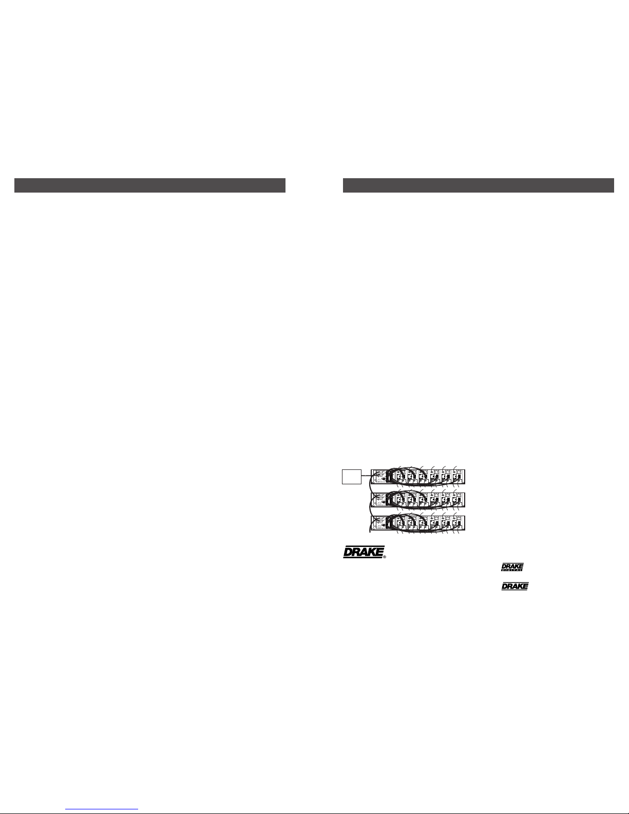
transcoders is then passed to and from each SCT transcoder via the power cables connecting each transcoder to the power supply. Up to 10 transcoders can be controlled with a single
connection to one PS150 or PS151 (or up to 6 SCT860s with a PS100). The DQT/MQM861
units are all self contained. When more than one tray of transcoders is installed, or when
DQTs or MQMs are also present, the data connection can simply be looped through all
associated PS100, PS150, and PS151 power supplies and the DQT861s and MQM861s to pick
up all of the transcoders. The maximum number of SCT860s that can be controlled as one
headend via a single RS232 connection is 63. The maximum number of SCT1860, SCT2860,
SCT3860, SCT4860 transcoders is 70 per headend. The maximum number of DQT861s and
MQM861s is 63.
It is possible to store files on your PC for more than one headend. Each headend file can
contain its specific parameters, connection type, dial-up number, password, etc. Thus, one PC
can be used to control multiple headend locations.
The PC may be connected directly to the PS100, PS150, PS151, DQT861, or MQM861 RS232
input DB9 connector via a standard serial data cable. If the control and monitoring is to be from
a remote site using a dial-up telephone line, modems may be used to make this connection. If
using a modem, a null modem cable is required.
2
INSTALLING THE PC SOFTW ARE
To install the control software, place the CDROM in the PC CDROM tray. The auto run routine
should produce a menu providing three selections:
1) Install SCT Control Program.
2) View various instruction manuals.
3) Install Adobe Acrobat Reader
To install the control software, choose the “Install SCT Control Program” option. If the
CDROM does not start automatically, Click on the "My Computer" icon on your PC desktop, then
click on the CDROM drive icon. To install the program, click on the setup.exe file on the
CDROM. Follow the prompts and when the program has been installed successfully, the
"DRAKE DIGITAL, R.L. Drake SCT Control Program" icon will appear on the PC desktop.
SETTING UP A REMOTE MODEM
If a pair of modems will be used to connect the PC to the headend via a dial up phone line, the
following procedure must be followed. The remote modem that will be located at the headend
equipment location must be set up for auto answer mode and it must also be set to
communicate at the same baud rate as the transcoder settings. If any other rate is used, the
transcoders will not respond.
The default RS232 baud rate is 4800 (factory default). It is suggested that this not be changed
unless your modem will not operate at this speed. Some modems may require a faster setting.
When changing the RS232 baud rate, be sure to change it in three places: 1) the setting on the
SCT/PS unit, set with front panel buttons. 2) the setting on the remote modem setup screen; 3)
the setting in the headend parameter screen. The easiest way to set up these parameters is to
temporarily connect the modem to a PC with this software program installed. Double click on the
DRAKE DIGITAL icon on the desktop and open the program. It is not necessary to have a
headend file set up at this point. Click on ‘Tools’ and again on ‘Remote Modem Setup’. Make sure
the PC is connected to the modem via a standard (not a null modem) RS232 serial port cable. If
you know that the command string must be altered, you may edit it from this screen. The factory
default values that are supplied should work with most currently available external modems.
Select the ‘Continue’ option. This will load the modem with the control character string that will
set up the proper parameters. When the pop up screen advises that the process is complete,
exit the program. The modem is now ready for installation at the headend. When the modem is
connected to the PS, a NULL MODEM CABLE MUST BE USED FOR THIS CONNECTION.
Reminder: Use a standard cable for setting up the baud rate and auto answer strings for the
remote modem but then use a null modem cable for the final installation connection of the remote
modem to the headend.
1
TM
R. L. DRAKE DIGIT AL HEADEND CONTR OL PROGRAM
CT DIGITAL HEADEND TRANSCODER REMO TE CONTROL SOFTW ARE
Here are the major issues to be addressed in order to set up your remote monitoring and
control:
■ Assigning UNIT ID numbers.
■ Installing the Drake Digital Headend Control Program on a PC.
■ Setting up a remote modem if a modem connection will be used.
■ Setting up your headend file or files.
■ Connecting to a Headend.
■ Setting a password, if desired.
A FEW WORDS ABOUT UNIT ID NUMBERS
In order to view settings or control a transcoder, it must be assigned a unique UNIT ID address
in the desired headend. The SCT1860/2860/3860/4860 series of transcoders uses a system
where the connected PS150 or PS151 is assigned a number from 1 to 7 and the 10
transcoders connected to that supply are automatically assigned a number between 1 and 10
determined by which socket they are connected to on the power supply. This results in an ID
number such as 7-10. The PS unit ID is set via the PS150/PS151 front panel buttons. You
cannot have more than one transcoder with the same ID. If the PS unit ID is set to 0, the
transcoders connected to that supply will not be seen or addressed by the remote control
software - control must be from the power supply panel.
The unit ID for DQT861 or MQM861 units is set from the front panel. See the instruction manual
SETTING UP HEADEND FILES
This procedure will set up a file for each new headend that you wish to control.
■ Open the R.L. Drake SCT file by double clicking the new DRAKE DIGITAL icon on the
desktop.
■ Click the "Setup New Headend" button.
■ Type in a name for the headend.
■ Select the Direct Connection or Modem choice.
■ Choose an available COM port. If you do not know which COM port your PC is using for the
modem or direct cable connection, go to the Control Panel folder located in your PC’s "My
Computer" folder. Look for the device properties for the modem or COM port. Usually this is
COM1 or COM2.
■ If the direct connection is used, press "OK" to connect.
■ If the baud rate (default is 4800) does not match the transcoder remote modem settings,
you may adjust it on this screen.
■ If the modem choice was selected, enter the phone number to be dialed. Use a comma for
a pause and be sure to add any long distance or outside line prefixes, if required.
Click OK to access the Modem Connection screen and then press the Connect button
to connect.
SETTING UP HEADEND FILES - continued
To set up a different headend location, close any existing connection, then use the "Setup New
Headend" button again and repeat the above steps for the second location. Add as many
locations as needed using this same procedure.
NOTES
(1) Right click on a headend name to edit or delete that headend if needed.
(2) This software contains factory default SCT parameter settings including presets for
certain popular services. These may or may not be the same settings that are factory loaded
into the transcoders themselves. You may wish to first set all parameters in the PC file for your
specific headend without connecting to the headend. You may then download these PC settings
to the headend with one command. If you wish to do this, proceed to the Off-line Editing
section.
To begin connecting to a headend now, skip the following "Off-line Editing" paragraph and refer
to the "Connecting to a Headend" paragraph.
OFF-LINE EDITING OF TRANSCODER PARAMETERS
To edit parameters off-line, choose the "Continue without Connecting" option from the modem
connection menu or if a direct connection is programmed, proceed as usual and edit the
appropriate PC files. Do not download the PC files to the transcoder but be sure to save
changes when prompted for this response.
CONNECTING TO A HEADEND
From the R.L. Drake SCT Control Program main screen, proceed as follows:
■ Click to highlight a desired headend name and select that headend.
■ Click on the "OK" selection.
If a direct connection is being used, this will make the connection.
If the modem choice was selected, enter the phone number to be dialed, if not already present.
Click on the "Connect" button to make the connection.
■ Once connected, the screen will display eight sets of transcoder info at a time. To speed up
the display refresh cycle, remove check marks from all unused transcoder numbers for all
transcoder screens. Click on the appropriate button to display another set of 8 transcoders.
■ If no data can be received from the transcoders, check the RS232 baud rate setting (right
click on headend name or select "edit" from the file menu). The setting must match the
transcoder setting. If necessary, use the remote modem setup procedure to program the
remote modem for this same baud rate.
4
3
PASSWORD PROTECTION
It is always possible to connect to the SCT headends with the RS232 control software,
regardless of password settings. However, without a valid password, you will only be able to
view the existing settings and edit the PC files. It will not be possible to download any new
parameters to the transcoders. This prevents unauthorized tampering with the headend settings
via the RS232 link. With SCT860s, DQT861s, or MQM861s each unit is set individually. With the
18/28/38/4860 units, the password is set on the PS150/PS151 and applies to all 10
transcoders per supply.
The factory default password is 0. If this password is not changed and the RS232 control
program is also kept at the default 0 setting, full access will be permitted. If password
protection is desired, program a new password. To do this, there must be a person at the
headend to put each transcoder or supply into the password programming mode.
Start the password program process by connecting to the headend, either by direct connection
or via a modem. You can always connect regardless of the password settings. After connecting
to the headend and while viewing the eight transcoder summary screen,
■ Click on the "Change Password" button.
■ In the space provided on the "Change Password" screen, enter your desired new password.
Do not click the ‘OK’ button yet.
■ Now have the person at the headend place all SCT860s, all PS150/PS151s, all DQT861s,
and all MQM861s to receive the password in the loading password mode by pressing the left
arrow, enter, and right arrow buttons simultaneously. Hold these until the that unit's display is
displaying the "Loading Password" message. Repeat on each SCT860, DQT, MQM, or power
supply until all displays are showing the "Loading Password" message.
■ Back at the PC, click on "OK" to transfer the password to the transcoders. It is essential that
this order is followed. The new password is now set in both the PC software and at the
transcoders.
■ Test the new password by downloading a PC file to a transcoder.
TM is a trademark of
R.L. Drake LLC
® is a registered trademark of
R.L. Drake LLC
© Copyright 2007 R.L. Drake LLC
P/N: 3852765C-02-2007
Printed in U.S.A.
R.L. DRAKE LLC
230 INDUSTRIAL DRIVE
FRANKLIN, OHIO 45005 U.S.A.
CUSTOMER SERVICE AND PARTS TELEPHONE:
+1 (937) 746-6990
TELEFAX: +1 (937) 806-1576
WORLD WIDE WEB SITE: http://www.rldrake.com
EIGHT TRANSCODER SUMMARY SCREEN DISPLA Y
Each summary screen displays four items of interest for each of eight transcoders: Mode,
satellite S/N, Output QAM symbol rate, and alarms or firmware version number. When the
View/Edit button is pushed for any one transcoder, the detailed parameter screen, showing a
full set of parameters, will be accessed.
DETAILED P ARAMETER SCREEN
When the "View/Edit" button is selected, this screen provides all parameter values for the
selected transcoder as stored in the PC file on the left side and the actual operating parameters in the SCT will be shown on the right side. The parameters in the left side PC file may be
changed without affecting the actual hardware operation. When desired, values from the PC
file may be downloaded to the transcoder from the screen. Alternatively, you may wish to
select other transcoders and adjust values as desired in the PC files and then return to the
summary screen and download all of the PC files to multiple transcoders in one operation.
Many times it will be desirable to set up the entire set of headend parameters off-line and then
download all of these PC files to the multiple transcoders.
POWER
RF OUT
EAS LNB
POWER
RF OUT
EAS LNB
POWER
RF OUT
EAS LNB
POWER
RF OUT
EAS LNB
POWER
RF OUT
EAS LNB
POWER
RF OUT
EAS LNB
POWER
RF OUT
EAS LNB
POWER
RF OUT
EAS LNB
POWER
RF OUT
EAS LNB
POWER
RF OUT
EAS LNB
POWER
RF OUT
EAS LNB
POWER
RF OUT
EAS LNB
POWER
RF OUT
EAS LNB
POWER
RF OUT
EAS LNB
POWER
RF OUT
EAS LNB
POWER
RF OUT
EAS LNB
POWER
RF OUT
EAS LNB
POWER
RF OUT
EAS LNB
PC
OR
MODEM
RS-232 CABLE CONNECTION
 Loading...