

Page 1
BW
AUTO
6.0
MODE
AM SYNC
A-B
TIME
MEM
VFO A = B
A = B
PRE ATTN
ANT 1 2 VHF
AGC S F
NOTCH
NB N W
NAME
TIMER
STEP
CLK/FREQ
LOCK
TUNE
SCAN
NOTCH TONE
SCAN
MEM
6.0
4.0
AM/
SYNC
FM
2.3
1.8 LSB USB
0.5
AUTO CW RTTY
BANDWIDTH
MODE
LIST
2
A - B
3
SEEK
4
TIME
5
CARR
6
CLK
7
LAMP
8
BEEP
9
F
DEL
0
V M
M V
SQUELCH
PASSBAND
OFFSET
VOL RF
MIN
0
-
+
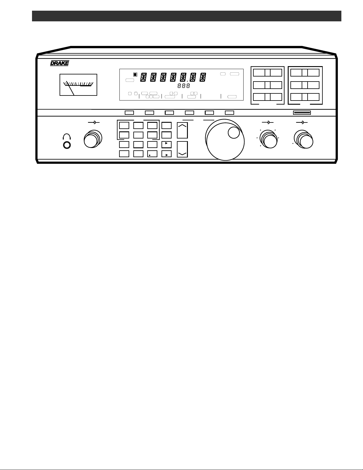
R8B Communications Receiver
1 3 5 7 9 20 40 60
S UNITS DECIBLES
SIGNAL
M/KHz
MEM
1
CLR
kHz
®
R8B Communications Receiver
Owner's Manual
© Copyright 1997 R. L. Drake Company P/N: 3851305A-9-1997 Printed in the U. S. A.
is a registered trademark of the R. L. Drake Company
®
Page 2
Declaration of Conformity
We, Manufacturer/Importer
(Full address)
R. L. Drake Company
Franklin, Ohio 45005 United States of America
(Description of the apparatus, system, installation to which it refers)
R8B Communications Receiver
(reference to the specifications under which conformity is declared)
in accordance with 89/336 EEC-EMC Directive
230 Industrial Drive
declare that the product
1294
is in conformity with
EN 55011
EN 55013
EN 55014
EN 55015
EN 55020
EN 55022
DIN V VDE 0855
part 10
part 12
CE marking
Limits and methods of measurement
of radio disturbance characteristics of
industrial, scientific and medical (ISM)
high frequency equipment
Limits and methods of measurement
of radio disturbance characteristics of
broadcast receivers and associated
equipment
Limits and methods of measurement
of radio disturbance characteristics of
household electrical appliances,
portable tools and similar electrical
apparatus
Limits and methods of measurement
of radio disturbance characteristics of
flourescent lamps and luminaries
immunity from radio interference of
broadcast receivers and associated
equipment
Limits and methods of measurement
of radio disturbance characteristics of
information technology equipment
Cabled distribution systems; Equipment
for receiving and/or distribution from
sound and television signals
EN 61000-3-2*
EN 61000-3-3*
EN 50081-1
EN 50082-1
prEN 55024-2
prEN 55024-3
pr EN 55024-4
prENV 50142
ENV 50141
(EC conformity marking)
Disturbances in supply systems caused
by household appliances and similar
electrical equipment "Harmonics"
Disturbances in supply systems caused
by household appliances and similar
electrical equipment "Voltage fluctuations"
Generic emission standard
Generic immunity standard
Electrostatic discharge requirements
"ESD" (IEC 801-2)
Radiated, radio frequency electromagnetic
field (IEC 801-3)
Electrical fast transient requirements
"Burst" (IEC 801-4)
Surge immunity requirements
(IEC 801-5)
Immunity to conducted disturbances
induced by radio frequency fields
above 9kHz (IEC 801-6)
* Replacement of
EN60555-2/-3
The manufacturer also declares the conformity of above mentioned product
with the actual required safety standards in accordance with LVD 73/23 EEC.
EN 60065
Safety requirements for mains operated
electronic and related apparatus for
household and similar general use
®
(Stamp)
EMC Tested by electronic GmbH
Ref. No. 953427 Name: G. Raithel Dipl.-Ing.
EN 60950
Manufacturer/Importer
Date: July 01, 1997 Name: Ronald E. Wysong____
Date: October 16, 1995 Signature ___________________
Safety for information technology equipment
including electrical business equipment
Signature ____________________
Page 3
WARNING: TO PREVENT FIRE OR
ELECTRICAL SHOCK DO NOT
EXPOSE TO RAIN OR MOISTURE
¡WARNING!
RISK OF ELECTRIC SHOCK
DO NOT OPEN
WARNING: TO REDUCE THE RISK OF ELECTRIC
SHOCK,
DO NOT REMOVE COVER (OR BACK)
NO USER-SERVICABLE PARTS INSIDE
REFER SERVICING TO QUALIFIED PERSONNEL
Important Safeguards i
An appliance and cart combination should be moved
with care. Quick stops, excessive force and uneven
surfaces may cause the appliance and cart combination to overturn.
The lightning flash with arrow head symbol, within an
equilateral triangle, is intended to alert the user to the
presence of uninsulated "dangerous voltage" within
the product's enclosure that may be of sufficient
magnitude to constitute a risk of electric shock to
persons.
The exclamation point within an equilateral triangle is
intended to alert the user to the presence of important operating and maintenance (servicing) instructions in the literature accompanying the appliance.
WARNING:
TO REDUCE THE RISK OF FIRE OR ELECTRIC SHOCK, DO NOT EXPOSE THIS APPLIANCE
TO RAIN OR MOISTURE.
DO NOT OPEN THE CABINET, REFER SERVICING TO QUALIFIED PERSONNEL ONLY.
CAUTION:
TO PREVENT ELECTRIC SHOCK, DO NOT USE THE THREE WIRE CORD WITH AN EXTENSION
CORD RECEPTACLE OR OTHER OUTLET UNLESS THE BLADES CAN BE FULLY INSERTED TO
PREVENT BLADE EXPOSURE.
ATTENTION:
POUR PREVENIR LES CHOCS ELECTRIQUES, NE PAS UTILISER CETTE FICHE POLARISEE
AVEC UN PROLONGATEUR, UNE PRISE DE COURANT OU UNE AUTRE SORTIE DE COURANT, SAUF SI LES LAMES PEUVENT ETRE INSEREES A FOND SANS EN LAISSER AUCUNE
PARTIE A DECOUVERT.
1. Read Instructions—All the safety and operating instructions should be
read before the appliance is operated.
2. Retain Instructions—The safety and operating instructions should be
retained for future reference.
3. Heed Warnings—All warnings on the appliance should be adhered to.
4. Follow Instructions—All operating and use instructions should be
followed.
5. Cleaning—Unplug this appliance from the wall outlet before cleaning.
Do not use liquid cleaners or aerosol cleansers. Use a damp cloth for
cleaning.
6. Do Not Use Attachments—not recommended by the manufacturer or
they may cause hazards.
7. Water and Moisture—Do not use this product near water—for example,
near a bathtub, wash bowl, kitchen sink, laundry tub, in a wet basement,
or near a swimming pool—and the like.
8. Accessories—Do not place this product on an unstable cart, stand,
tripod, bracket, or table. The product may fall, causing serious injury to a
child or adult, and serious damage to the appliance.
9. Ventilation—This product should never be placed near or over a
radiator or heat register. This product should not be placed in a built-in
installation such as a bookcase or rack unless proper ventilation is provided
or the manufacturer’s instructions have been adhered to. Any slots or
openings in the cabinet are provided for ventilation. To ensure reliable
operation of the video product and to protect it from overheating, these
openings must not be blocked or covered. The openings should never be
blocked by placing the product on a bed, sofa, rug, or other similar surface.
10. Grounding or Polarization—This product is equipped with a 3- wire
line cord receptacle. It is intended for use with a 3-wire properly grounded
power socket. Do not defeat the safety purpose of the supplied line cord
and plug.
10A. Mise à la terre ou Polarisation—Cet appareil est équipé avec un
cordon d'alimentation à trois fils. Il est a brancher sur une prise ayant un
connecteur a la terre. Assurez-vous que la connection a la terre ne manque
pas.
11. Power Sources—This product should be operated only from the type
of power source indicated on the marking label. If you are not sure of the
type of power supplied to your home, consult your appliance dealer or local
power company.
12. Power-cord Protection—Power-supply cords should be routed so
they are not likely to be walked on or pinched by items placed upon or
against them. Pay particular attention to cords at plugs, convenience
receptacles, and the point where they exit from the appliance.
13. Lightning—For added protection for this product during a lightning
storm, or when it is left unattended and unused for long periods of time,
unplug it from the wall outlet.
14. Power Lines—An outside antenna system should not be located in the
vicinity of overhead power lines, other electric light or power circuits, where
it can fall into such power lines or circuits. When installing an outside
antenna system, extreme care should be taken to keep from touching such
power lines or circuits as contact with them may be fatal.
Page 4
ii Important Safeguards, continued
15. Overloading—Do not overload wall outlets and extension cords as this
can result in a risk of fire or electric shock.
16. Object and Liquid Entry—Never push objects of any kind into this
product through openings as they may touch dangerous voltage points or
short-out parts that could result in a fire or electric shock. Never spill liquid
of any kind on the product.
17. Servicing—Do not attempt to service this product yourself as opening
or removing covers may expose you to dangerous voltage or other
hazards. Refer all servicing to qualified service personnel.
18. Damage Requiring Service—Unplug this product from the wall outlet
and refer servicing to qualified service personnel under the following
conditions:
a. When the power-supply cord or plug is damaged.
b. If liquid has been spilled, or objects have fallen into the product.
c. If the product has been exposed to rain or water.
d. If the product does not operate normally by following the operating
instructions. Adjust only those controls that are covered by the operating
instructions. An improper adjustment may result in damage and will often
require extensive work by a qualified technician to restore the product to its
normal operation.
e. If the product has been dropped or the cabinet has been damaged.
f. When the product exhibits a distinct change in performance—this
indicates a need for service.
19. Replacement Parts—When replacement parts are required, be sure
the service technician has used replacement parts specified by the
manufacturer or have the same characteristics as the original parts.
Unauthorized substitutes may result in fire, electric shock or other hazards.
20. Safety Check—Upon completion of any service or repairs to this
product, ask the service technician to perform safety checks to determine
that the product is in proper operating condition.
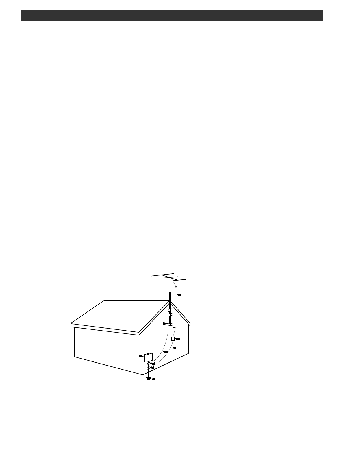
21. Outdoor Antenna Grounding—Before attempting to install this product, be sure the antenna or cable system is grounded so as to provide some
protection against voltage surges and built-up static charges.
a. Use No.10 AWG (5.3mm
No.17 AWG (1.0mm
2
) copper, No.8 AWG (8.4mm2) aluminum,
2
) copper-clad steel or bronze wire or larger, as ground
wire.
b. Secure antenna lead-in and ground wires to house with stand-off
insulators spaced from 4 feet (1.22m) to 6 feet (1.83m) apart.
c. Mount antenna discharge unit as close as possible to where lead-in
enters house.
d. A driven rod may be used as the grounding electrode where other types
of electrode systems do not exist. Refer to the National Electrical Code,
ANSI/NFPA 70-1990for information.
e. Use jumper wire not smaller than No.6 AWG 13.3mm
2
) copper or
equivalent, when a separate antenna grounding electrode is used.
"EFFECTUER LE CABLAGE CONFORMEMENT AU CODE CANADIEN DE L' ELECTRICITE"
" INSTALL WIRING ACCORDING TO THE CANADIAN ELECTRICAL CODE"
EXAMPLE OF ANTENNA GROUNDING
ANTENNA
LEAD IN
WIRE
GROUND CLAMP
ANTENNA
DISCHARGE UNIT
(NEC SECTION 810-20)
ELECTRIC
SERVICE
EQUIPMENT
NEC - NATIONAL ELECTRIC CODE
GROUNDING CONDUCTORS
(NEC SECTION 810-21)
GROUND CLAMPS
POWER SERVICE GROUNDING
ELECTRODE SYSTEM
(NEC ART 250, PART H)
Page 5

Table of Contents iii
Thank you for purchasing a Drake R8B Communications
Receiver. This receiver has been designed and manufactured to high quality standards, and will provide
reliable operation for many years.
Important Safeguards
Table of Contents
Introduction
General Description
Specifications / Accessories
Safety Voltage Selection
Installation
Unpacking
Location
Fixed Installation
Mobile Installation
Antenna Requirements
Installation Diagram
Front Panel Description
i
iii
1
1
2
3
4
5
6
Please carefully read the Owner's Manual in order to
take advantage of the many interesting features that
will provide enjoyable listening to radio broadcasts
around the world.
Memory Functions
Memory Channel Programming
Recalling A Memory Channel
Deleting A Memory Channel
Erase All Memory Channels
Locking A Memory Channel
Scan Functions
Scan Memory
Scan Memory List Block
Locking A Memory Channel
Scan A - B
Important Notes About Scanning
Clock and Timer Functions
Time Display
Setting The 24 Hour Clocks
Timer Operation
Setting Timer On/Off Times
Enabling/Disabling Timer Operation
Timer Connector Interface
17
18
18
18
18
18
19
19
20
20
21
21
22
22
22
22
22
23
25
Front Panel Display
Rear Panel Description
Mute Operation of the Receiver
Getting Started
General Operating Information
Microprocessor Reset
Beep Tones
Getting Started
Frequency Step Selection
Dual VFO's
Direct Frequency Entry
Front Panel Lock
Passband Offset Operation
Notch Operation
AM Synchronous Detector
RF Function (Attenuator/Preamplifier)
Noise Blanker
CW Operation
RTTY Operation
SSB Operation
FM Operation
Gain and AGC Operation
8
10
11
12
12
12
12
12
12
13
13
14
14
14
14
15
15
15
15
15
16
16
Special Use Features and Functions
Function Line Invert
Setting Power Off (On) Lamp Brightness
10 kHz/9 kHz Scan
Delete All Memory Locations
Power On Button Functions
Held Button Functions
RS232C Interface
Glossary of Terms
Suggested References
Quick Reference Guide
Troubleshooting
Special Display Messages
Service
Warranty
26
26
26
26
26
26
26
27
31
32
33
35
35
36
37
Warning: The R8B Communications Receiver complies with FCC
rule Part 15. Any changes or modifications to the receiver, without
expressed approval of the R. L. Drake Company, could cause the
receiver to violate the FCC Compliance rules.
Page 6

iv
This page left intentionally blank.
Page 7
R8B Communications Receiver
1 3 5 7 9 20 40 60
S UNITS DECIBLES
SIGNAL
SCAN
MEM
SEEK
LIST
TIME
A-B
CARR
VFO A = B
A = B
F
ANT 1 2 VHF
PRE ATTN
Introduction - General Description 1
AM/
SYNC
FM
MODE
MEM
TUNE
AGC S F
NOTCH
NB N W
NAME
4.0
BW
AUTO
6.0 4.0
2.3 1.8
0.5
MODE
AM SYNC
LSB USB
CW FM
RTTY
CLK/FREQ
LOCK
MHz
kHz
12 ON OFF
TIMER
STEP
6.0
1.8 LSB USB
2.3
AUTO CW RTTY
0.5
BANDWIDTH
NOTCH TONE
SCAN
LIST
MEM
1
SEEK
4
CLK
7
F
A - B
2
TIME
5
LAMP
8
DEL
0
SCAN
3
CARR
MEM
6
BEEP
V M
9
CLR
M/KHz
M V
The R8B communications receiver is a microprocessor
controlled, synthesized, all mode, world band receiver
with continuous coverage capability from 100 through
30,000 kHz. The receiver offers excellent sensitivity, selectivity, high dynamic range and offers features for the most
demanding shortwave reception. Conveniently located
front panel controls allow for rapid operator programming and ease of use. Operating mode and corresponding bandwidth are quickly selected by front panel buttons. The selectable AC input allows for operation around
the world. In addition, a DC input is provided for mobile
operation.
A High-Q, 8-pole, electronically switched IF filter provides
a range of five commonly used bandwidths. These bandwidths are automatically selected by mode, however
any bandwidth may be selected at the touch of a button.
TUNE
PASSBAND
OFFSET
VOL RF
SQUELCH
0
-
+
MIN
A PASSBAND OFFSET control also aids in reducing or
eliminating interfering signals by electronically shifting the
receiver's IF frequencies without disturbing the operating
frequency. This action allows the operator to electronically move interfering signals out of the receiver’s passband thus utilizing the high degree of selectivity provided
by the High-Q, 8-pole IF filter.
Other built-in reception aids include selectable AGC
speed, dual antenna inputs, noise blanker(NB), RF preamplifier for enhancing weak signals, RF attenuator for further
improvement of strong signal handling capabilities, adjustable RF gain, NOTCH, TONE and SQUELCH controls.
Two independent, real time clocks provide a local and
alternative time selection. Also provided is a two event
timer.
The front panel liquid crystal display provides visual feedback to the operator of the current status of the receiver.
The seven digit frequency display allows tuning resolution
to 10 Hz accuracy.
In the AM mode, a selectable sideband synchronous
detector (SYNCHRO) allows for enhanced reception by
eliminating or reducing distortion due to fading signals
and allowing the passband to be shifted toward one
sideband, to reject interference, without causing audio
distortion.
A programmable memory area allows for 1000 independent receive memories. In addition, these memories are
stored in a battery backed-up memory chip to ensure
memory retention during power line failure. Any of these
memories may be altered by the operator and re-stored.
These memory channels may be accessed manually or
by various scanning methods.
Finally, a built-in RS-232 compatible interface allows complete digital control of the receiver including memory and
scanning functions.
Page 8

2 Introduction - Specifications / Accessories
Frequency Range
Modes
Sensitivity: SSB, CW (10dB
S+N/N)
Sensitivity: AM
(10dB S+N/N, 1000 Hz,
30% mod)
Sensitivity: FM
(12 dB SINAD)
Frequency Stability
Frequency Accuracy
Selectivity: AM, LSB, USB,
RTTY, CW
FM Only
100-30,000 kHz
AM, LSB, USB, CW, RTTY, FM
0.5 µV nominal, 100-30,000 kHz
(preamp off)
Less than 0.25µV, 100-30,000 kHz
(preamp on)
1.5 µV nominal, 100-30,000 kHz
(preamp off)
Less than 1.0 µV, 100-30,000 kHz
(preamp on)
Less than 0.5 µV, 100-30,000 kHz
±5ppm, -100 to 500 C
Better than ±100 Hz, -100 to
500 C
6 KHz @ -6 dB, less than 12 kHz
@ -60 dB
4 KHz @ -6 dB, less than 8 kHz
@ - 60 dB
2.3 KHz @ -6 dB, less than
4.5 KHz @ -60 dB
1.8 KHz @ -6 dB, less than
3.6 KHz @ -60 dB
500 Hz @ -6 dB, less than
1.5 KHz @ -60 dB
12 KHz @ -6 dB, less than
25 KHz @ -60 dB
IP3 - Intercept Point
(preamp off)
1st IF
2nd IF
AGC
Ant 1, Converter
Ant 2
Notch Filter Attenuation
External Speaker Output
Line Outputs
AC Power Requirements
DC Power Requirements
+20 dBm @
100 kHz spacing
-20 dBm @
5 kHz spacing
45 MHz
50 kHz
Threshold: 0.8 µV
Attack time: 1mS
Release time: SLOW: 2 Sec
FAST: 300mSec
Nominal 6 dB change in audio output for 100 dB input
change above AGC
threshold
50 Ohms unbalanced
50 or 500 Ohms unbalanced
AF type, 40 dB min. Depth
(500-5000 Hz)
2.5 W, 4 Ohms @ less than
5% distortion
300 mV, 4.7K Ohms
100/120/200/240VAC,
±10%
50 or 60 Hz, 40 Watts
nominal
11-16 VDC @ 2 A
Ultimate Selectivity
Image Rejection
IF Rejection
Dynamic Range
ACCESSORIES
Accessories for the receiver include:
1) A VHF converter with frequency coverage of 35-55 MHz
and 108-174 MHz.
2) A complementary styled MS8 external speaker.
Greater than 95 dB
Greater than 80 dB,
100-30,000 kHz
Greater than 80 dB, 45 MHz
Greater than100 dB, 50 kHz
97 dB, 100-30,000 kHz @ 100 kHz
spacing
Operating Temperature
Weight
CAUTION: The optional VHF Converter accessory should
be installed by a qualified service technician to prevent
personal injury or damage to the equipment.
-100 to +500 Celsius
13 lbs. (5.9 Kg)
Size
Width 13 1/8" (33.4 cm)
Height 5 1/4" (13.4 cm) including feet
Depth 13" (33 cm), including front knobs and rear
connectors
Page 9

SAFETY/VOLTAGE SELECTION
WARNING!!!
Please read before applying power
Introduction - Safety / Voltage Selection 3
The receiver is normally shipped with the input line voltage
selector switch set to 108-132 VAC for operation in the U.S.
and Canada. If your operating voltage is different than
this, please refer to FIGURE 1 below. The voltage select
switch is located on the rear panel and must be set to the
proper voltage range for your area. In addition, the
proper mains fuse may need to be installed. The unit may
be set to operate over the following voltage ranges: 90110 VAC, 108-132 VAC, 180-220 VAC and 216-264 VAC.
Most countries outside the U.S. and Canada use either
220 VAC or 240 VAC line voltage. Please be certain of the
operating voltage before connecting to the mains source.
The receiver will operate on either 50 Hz or 60 Hz line
frequency.
_________________________________________________________________
Note: The warranty does not cover damage as a result of
improper voltage selection, or replacement of fuse with
ratings other than those specified.
_________________________________________________________________
FIGURE 1 VOLTAGE SELECTOR SWITCH SETTINGS
Setting for 108-132 VAC
Fuse rating 400mA
Setting for 90-110 VAC
Fuse rating 400mA
Antenna grounding is necessary if the unit is connected to
an outdoor antenna. Grounding of the antenna system
is required to protect against static build up and voltage
surges. Refer to section 810-21 of the National Electric
Code, ANSI/NFPA No. 70-1990.
The power cord and antenna lead-in should be disconnected if the unit is not to be used for an extended period
of time or if threatening weather containing damaging
lightning is likely.
CAUTION
WARNING
DISCONNECT FROM
SUPPLY BEFORE
CHANGING RANGES
108-
132V
90-
110V
180-
220V
264V
216-
Setting for 180-220 VAC
Fuse rating 200mA
WARNING
DISCONNECT FROM
SUPPLY BEFORE
CHANGING RANGES
180-
108-
220V
132V
110V
264V
216-
90-
WARNING
DISCONNECT FROM
SUPPLY BEFORE
CHANGING RANGES
90-
110V
108-
132V
264V
216-
220V
180-
Setting for 216-264 VAC
Fuse rating 200mA
WARNING
DISCONNECT FROM
SUPPLY BEFORE
CHANGING RANGES
216-
264V
220V
180-
132V
110V
108-
90-
In accordance with international safety
standards, this instrument is equipped with
a three-wire power cable receptacle. The
unit is shipped with a detachable type threewire power cable intended for nominal
115/127 VAC mains supply. When connected to an appropriate power line outlet, this cable grounds the instrument cabinet. For operation of this unit on nominal
220/240 VAC mains supply, use the proper
power cable assembly approved by your
local codes.
For use of this product outside the U. S. A. or
Canada on supply voltages of 220 VAC or
greater, the discharge resistor (4.7 Meg
Ohm) connected from the neutral wire terminal of the AC input receptacle to the
receiver chassis must be removed.
Refer modification to a qualified service
technician.
Page 10
4 Installation
UNPACKING
Carefully remove the receiver from the shipping carton
and examine it for evidence of damage. If any damage
is noted, immediately contact the transportation company responsible for delivery or return the unit to the
dealer from whom it was purchased. Keep the shipping
carton and all packing material for the transportation
company to inspect. The original carton and packing
material should be retained for repackaging should it be
necessary to return the unit. Inspect the packing material
for any accessories or printed material before storing the
box. Locate the registration card, fill out, and immediately return to the R. L. Drake Company to insure registration and validation of warranty.
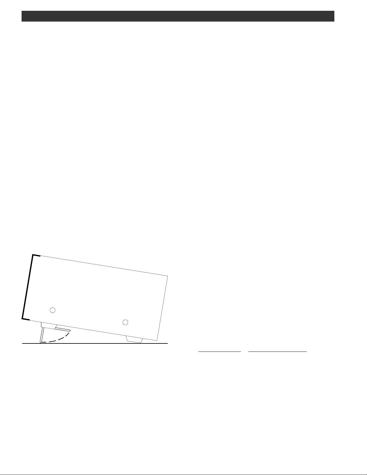
LOCATION
The location of the receiver is not critical so long as
adequate clearance is provided to allow air circulation in
and around the unit. Do not cover any ventilation slots in
top cover or overheating may result. The ventilation slots
also double as a speaker grill and any blockage may
result in poor sound quality. For added operating convenience, the front bail may be flipped down to elevate the
front of the unit. Refer to Figure 2
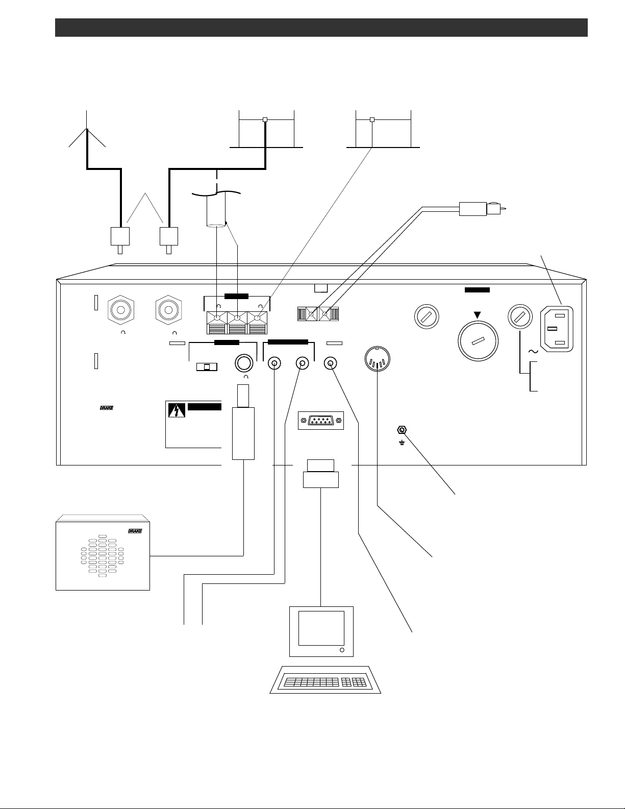
FIXED INSTALLATION
After unpacking the unit and checking the voltage select
switch for proper setting and correct fusing, connect
antenna system to the appropriate antenna input. Connect AC cord to mains voltage. Connect ground system
to ground screw on rear panel of radio. Connect any
other external equipment at this time. Refer to Figure 3 for
the diagram of a typical fixed installation.
MOBILE INSTALLATION
For use in a mobile environment, the receiver includes a
fused external DC input connector. This connector is
located on the rear panel. The receiver works well with a
DC input voltage of 11-16 VDC. Typical automotive
systems supply 13.8 VDC. Due to the relatively low current
draw, the receiver may be powered from the vehicle’s
cigarette lighter socket. Connect DC power cord observing the correct polarity. An internal protection device will
protect the receiver from reverse polarity hookup. Connect the mobile antenna(s) to appropriate antenna
input(s). This will typically be a whip antenna with a
coaxial cable thus permitting the cable to be run under
floor mats, etc. Connect a grounding wire from the
grounding screw on the rear panel to the vehicle's chassis. To further reduce current draw from the vehicle’s
battery system, it is recommended the LCD backlighting
be turned off for extended listening periods.
Side View of Receiver
FIGURE 2 ADJUSTING FRONT BAIL
ANTENNA REQUIREMENTS
The receiver incorporates internal switching to allow two
separate antenna systems to be connected simultaneously. Refer to Figure 3. Ant 1 is a 50 Ohm , SO-239
coaxial input requiring a mating PL-259 connector. This
input would typically be used as the primary antenna
input. Antennas such as dipoles, trapped dipoles, verticals and beams will provide the best results. Ant 2 is a
compression terminal type connection, providing a choice
of high impedance (500 Ohms typical) or low impedance
(50 Ohms typical). Antennas such as long wires or end fed
Zepps will provide the best results. The best antenna will
depend on the frequency range and time of day for the
particular signal in question. Refer to publications such as
the ARRL Handbook or ARRL Antenna Manual (available
in most public libraries) for help on selection and/or construction of the antennas mentioned above.
Page 11
Installation, continued 5
FOR USE WITH
OPTIONAL VHF
CONVERTER
50 OHM
COAXIAL
CABLE
CONV
50
MADE IN U. S. A.
BY ®
50 OHM COAXIAL CABLE
PL-259
ANT 1
- OR -
50 GND 500
50
INT EXT
BOTH
W A R N I N G
RISK OF ELECTRIC
SHOCK DO NOT OPEN
AVIS
RISQUE DE CHOC
ELECTRIQUE NE PAS OUVRIR
DIPOLE
LOW IMPEDANCE
A N T 2
SPEAKER
EXT OUT OUT MUTE
4
LINE AUDIO
OR
- +
EXT 11 - 16 VDC IN
INTERFACE
RS - 232C
LONGWIRE
HIGH IMPEDANCE
2A
TYPE T
TIMER
GND
ATTENTION: LOCATE ANY
RECEIVER ANTENNAS SOME
DISTANCE AWAY FROM
TRANSMITTER ANTENNAS TO
AVOID POSSIBLE DAMAGE TO
THE RECEIVER
DC POWER PLUG TO
VEHICLE'S LIGHTER SOCKET
AC POWER CORD
CONNECTION
WARNING
DC
DISCONNECT FROM
SUPPLY BEFORE
CHANGING RANGES
108-
132V
110V
180-
220V
264V
216-
CAUTION: - RISK OF FIRE -
REPLACE FUSE AS MARKED AFTER
DISCONNECTING UNIT FROM AC LINE.
ATTENTION:- RISQUE D'INCENDIE -
REMPLACEZ FUSIBLE DU TYPE INDIQUÉ
APRÉS DEBRANCHER DU SECTEUR.
AC
90-
40 WATTS 50/60 Hz
100VAC 400 mA
120VAC 400 mA
200VAC 200 mA
240VAC 200 mA
TYPE T
MS8 Speaker
EXTERNAL SPEAKER
(MS8)
EQUIPMENT WITH LINE AUDIO
TO PERIPHERAL
INPUTS SUCH AS CW/RTTY
DEMODULATORS, TAPE
RECORDERS , ETC.
TO GOOD EARTH GROUND
(POWER SERVICE GROUNDING, ELECTRODE SYSTEM OR
WATER PIPE)
TO PERIPHERAL
EQUIPMENT WITH TIMED ON/
OFF CONTROL SUCH AS
TAPE RECORDERS
TO PERIPHERAL
EQUIPMENT PROVIDING
MUTING CONTROL SUCH AS
TRANSMITTERS
TERMINAL
FIGURE 3 INSTALLATION DIAGRAM
Page 12
6 Front Panel Description
1 2 3 4
R8B Communications Receiver
1 3 5 7 9 20 40 60
S UNITS DECIBLES
SIGNAL
SCAN
MEM
SEEK
LIST
TIME
A-B
CARR
VFO A = B
A = B
F
ANT 1 2 VHF
PRE ATTN
MEM
TUNE
AGC S F
NOTCH
NB N W
NAME
4.0
BW
AUTO
6.0 4.0
2.3 1.8
0.5
MODE
AM SYNC
LSB USB
CW FM
RTTY
CLK/FREQ
LOCK
MHz
kHz
12 ON OFF
TIMER
STEP
6.0
1.8 LSB USB
2.3
AUTO CW RTTY
0.5
BANDWIDTH
AM/
SYNC
FM
MODE
NOTCH TONE
SCAN
LIST
MEM
1
SEEK
4
CLK
7
F
A - B
2
TIME
5
LAMP
8
DEL
0
SCAN
3
CARR
MEM
6
BEEP
V M
9
CLR
M/KHz
M V
TUNE
PASSBAND
OFFSET
VOL RF
SQUELCH
0
-
+
MIN
14 13 12 11 10 9 8 7 6 5
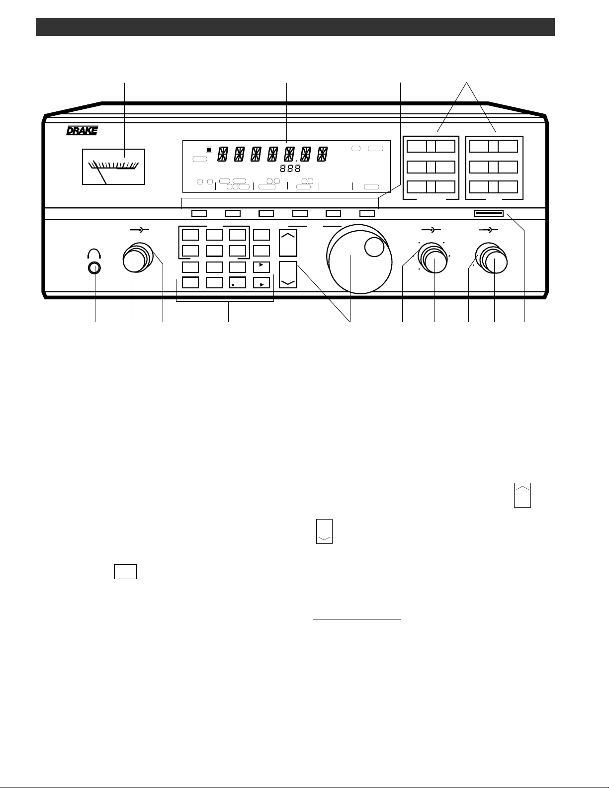
FIGURE 4 FRONT PANEL
1) SIGNAL - This meter indicates the relative signal level in
S-units and dB above S9.
2) Display - The backlit, liquid crystal display provides the
current status of the receiver such as frequency, mode,
bandwidth, etc. Refer to the FRONT PANEL DISPLAY
section of this manual for a full description.
3) Function Buttons - These (6) buttons control the various
functions of the receiver which are indicated on the
display directly above each button.
4) MODE/BANDWIDTH Buttons - The operating mode and
bandwidth are directly entered with these front panel
buttons. Press the AUTO button to permit automatic
setting of bandwidth as mode is selected. Press the AM/
SYNC button to enable the synchronous detector in AM
AM/
mode. Press the
button to turn the synchronous
SYNC
detector off before selecting LSB or USB modes.
5) POWER - This button turns the receiver on or off. When
unit is off, the clock will be displayed.
6) VOLUME - This control adjusts the receiver’s audio
speaker level. Turn clockwise to increase level or counterclockwise to decrease level.
7) RF - This control adjusts the gain of the receiver and is
normally left in the fully clockwise position for maximum
gain.
8) PASSBAND OFFSET - This control alters the position of the
receiver’s IF passband without disturbing the main tuning.
Normally, this control should be set at the “0” or 12 o’clock
position. This control is not active in FM mode.
9) SQUELCH - This control sets the signal level at which the
audio is muted. For normal operation, this control is set
fully counterclockwise.
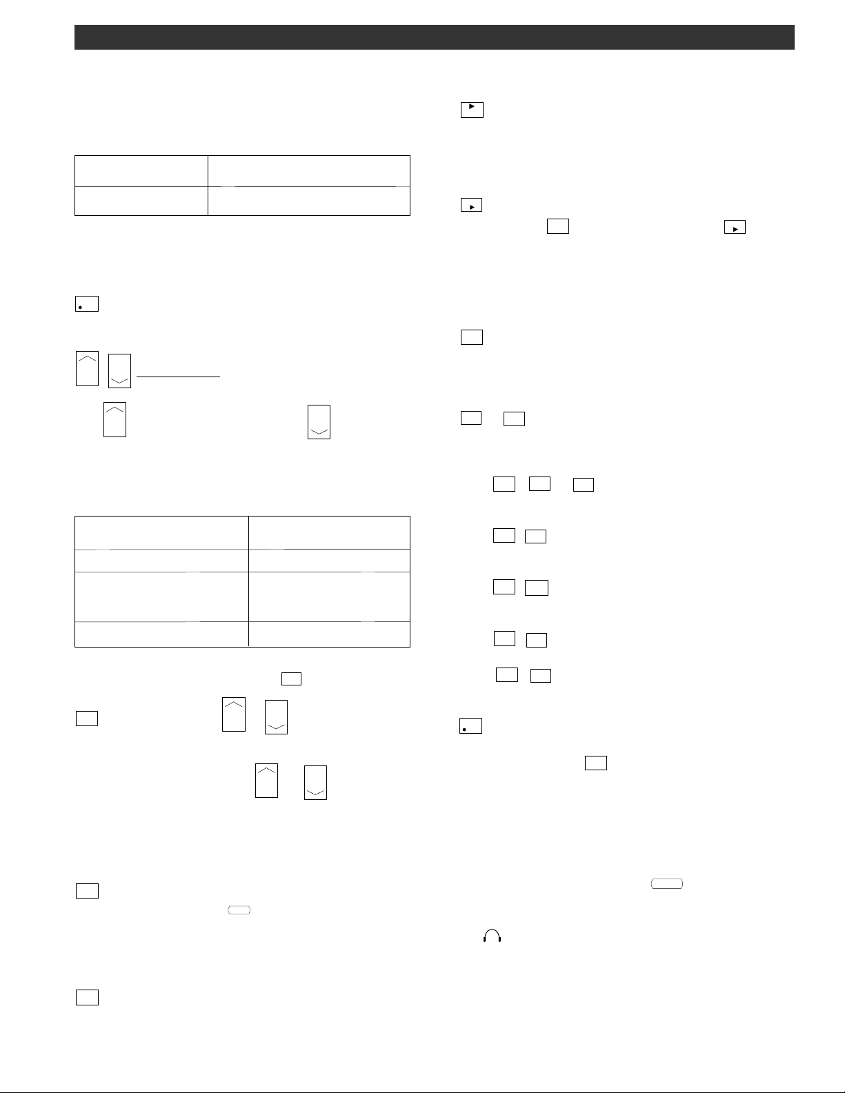
10) TUNING (VFO) - The tuning wheel and the
buttons are the primary tuning controls of the re-
ceiver. Clockwise rotation of the tuning wheel increases
frequency and counterclockwise rotation decreases frequency. The tuning wheel also incorporates variable
speed tuning. The faster the tuning wheel is rotated, the
faster the tuning speed.
TUNING WHEEL STEPS
The receiver can be programmed to tune in three
different resolutions (steps) with the corresponding
display readout. The three choices are as follows:
A) 1 kHz display readout (tuning in 1 kHz steps).
Used for fairly rapid frequency search.
B) 100 Hz display readout (tuning in 100 Hz steps).
Used for tuning AM and FM signals.
C) 10 Hz display readout (tuning in 10 Hz steps).
Used for tuning SSB, CW, or data signals.
and
Page 13
Front Panel Description, continued 7
V M
F
BEEP
9
F
The step size may be programmed per mode. The receiver, as shipped from the factory, has step sizes programmed as shown in Table 1 below:
Tuning and
Mode
LSB, USB, RTTY, CW
AM, FM
Display Resolution (Hz)
10
100
Table 1
To reset the receiver to the factory settings for STEP size,
AGC setting, BANDWIDTH, etc.:
Press the POWER button to turn the receiver off. Press the
CLR
button and hold while pressing the POWER button to
turn Power on. After three seconds, the receiver will reset.
BUTTON STEPS
The button increases and the button decreases the frequency by fixed steps with each depres-
sion as programmed. Pressing and holding either button
will allow continuous stepping up or down as long as the
button is depressed. The fixed steps are as follows:
Frequency Range
100-540 kHz
540-1800 kHz
Step
5 kHz
AM mode: 10 kHz
(9 kHz if programmed)
Other modes: 5 kHz
1800-30,000 kHz
To tune in 100 kHz steps, press the
F
displayed, press the / buttons, as desired,
5 kHz
F
button. With the
to tune in 100 kHz increments.
Note that, regardless of the / button step
(VFO to Memory) - Pressing this button in VFO mode
transfers the current status of the receiver, for example,
frequency, mode, bandwidth, etc., into memory. Please
refer to the MEMORY FUNCTIONS section of this manual for
details.
M/KHz
(MHz or kHz Frequency Readout or Memory to VFO)
M V
- Pressing the
F
button followed by the
M/KHz
M V
button,
changes the frequency readout to MHz or kHz as desired.
Pressing this button in memory mode transfers the contents of the current memory location, i.e., frequency,
mode, bandwidth, etc. to the selected VFO. Refer to the
MEMORY FUNCTIONS section of this manual for details.
(Function) - Pressing this button accesses secondary
functions, printed in orange, on the numeric buttons 0-9
and switches the function line on the display above the 6
function buttons.
DEL
to
0
- These buttons are normally used for direct
numeric entries in VFO, memory, clock, and timer modes.
Each button also has a secondary function printed in
orange. These secondary functions are used as follows:
Press
F
,
1
to
CARR
for programming scan methods.
6
MEM
Refer to the SCAN FUNCTIONS section of this manual for
details.
F
CLK
,
Press
to access the clock. Refer to the CLOCK
7
& TIMER FUNCTIONS section of this manual for details.
F
LAMP
,
Press
to adjust display and signal meter back-
8
light intensity.
F
Press
BEEP
,
to turn audible beep on or off. Refer to
9
BEEP TONES page 12.
F
DEL
,
Press
to delete a program from a memory
0
location. See DELETING A MEMORY LOCATION page 18.
CLR
(Decimal) - This button is used when entering a
frequency directly with the numeric buttons. Also used in
conjunction with the
button to provide a Clear entry
function. See DIRECT FREQUENCY ENTRY page 13.
increments, the display always indicates the programmed
tuning resolution (step) available by using the tuning
wheel at any frequency.
11) Program Buttons -
SCAN
(Scan) - Pressing this button starts a scan as defined
SCAN
by the scan indicators (
) on the display.
MEM
SEEK
LIST
TIME
A-B
CARR
Please refer to the SCAN FUNCTIONS section of this
manual for details.
MEM
(Memory) - Pressing this button in VFO mode switches
the receiver to memory mode. Please refer to the MEMORY
FUNCTIONS section of this manual for details.
12) TONE - This control is used to modify the tonal quality
of the audio. Counterclockwise rotation increases bass
response. Flat response occurs at the 12 o'clock setting.
13) NOTCH - This control is used to “tune” the notch
frequency and is active when
NOTCH
is displayed. This
control is not active in FM mode.
14)
Headphone - This connector accepts a standard
1/4" diameter 2-circuit (monaural) or 3-circuit (stereo)
phone plug. Audio is monaural in either case. All speaker
outputs are automatically switched off when using headphones.
Page 14
8 Front Panel Display
A B CARR
12 ON OFF
F
4
6
7
SCAN
MEM
SEEK
LIST
TIME
A-B
CARR
VFO A = B
A = B
PRE ATTN
ANT 1 2 VHF
911210 13 12 15 14
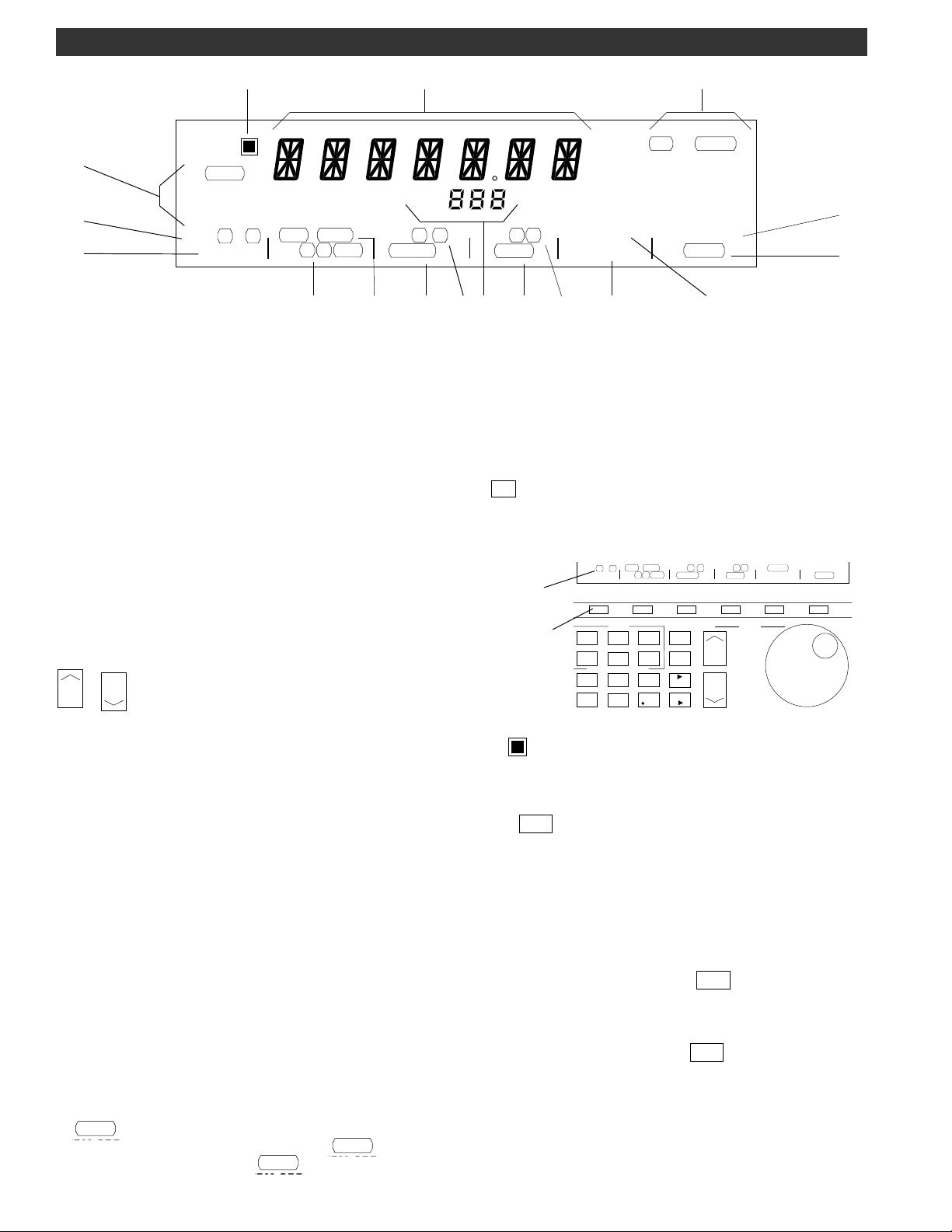
1) 7-Digit Apha/Numeric Display Readout - This display
indicates frequency, in ‘MHz’ or ‘kHz’ as selected, of the
current VFO or Memory channel. The readout will also
display the channel name if assigned and selected in
addition to various programming and error messages. For
memory list scans, the two left-most digits display an Index
number. In the clock mode, indicates either ‘Local’ or
‘Universal’ time in 24 hour format as selected. Time display
is as follows: HH:MM:SS. In the Timer mode, indicates time
in 24 hour format as follows: HH:MM, with no seconds
indicated.
2) MEM/TUNE - This annunciator indicates the current
memory location. ‘MEM’ will light when the receiver
enters the Memory mode and all memory channel
locations can be sequentially tuned by use of the ‘TUNE
/ ’ buttons or Tuning wheel. With 'TUNE'
displayed, use of the Tuning wheel will allow the the user
to tune away from the selected memory channel.
3) BANDWIDTH/MODE Indicators - The currently selected
IF filter Bandwidth and mode of reception are indicated.
For FM mode operation, only the mode (FM) is displayed.
When ‘AUTO’ is illuminated, the appropriate bandwidth is
automatically set for the corresponding selected mode.
Note: The AGC setting, tuning step size, display resolution
and bandwidth are user programmable and stored per
mode. The modes are:
AM - Amplitude Modulation
AM/SYNC - Amplitude Modulation (with Synchronous
Detection)
AM SYNC, LSB, USB - Amplitude Modulation with Synchronous Detection of either the selected upper or lower
sideband portion of an AM signal.
FM - Frequency Modulation
CW - Continuous Wave (Morse Code)
RTTY - Radio Teletype or data
LSB - Lower Sideband
USB - Upper Sideband
4)
- The annunciators under this heading indicate
SCAN
the current scan function programming.
when the receiver enters the
Refer to the ‘Scan Functions’ section of this manual.
SCAN
mode.
15
MEM
TUNE
AGC S F
NOTCH
NB N W
NAME
8
FIGURE 5 FRONT PANEL DISPLAY
IMPORTANT - PLEASE READ
The function lines of the display, described in callouts 5)
through 17) are activated by the unmarked function
button located directly below the displayed function.
The primary function line is the top most line. Pressing the
F
allows access to the alternate function line (lower
line). Alternate function availability ‘times out’ after any
front panel activity which alters the display.
Function
Lines
Function
Buttons
F
5)
nate function selection is enabled.
6) VFO A/B - This annunciator indicates the VFO in use. A
box
7) A=B - An ‘=’ sign appears between the ‘A’ and ‘B’ of the
top function line to indicate that one of the VFO’s has
been set to the same frequency as the other. This function
serves as a temporary ‘scratchpad’ memory of the first
VFO frequency as the second VFO frequency is changed
by tuning.
8) PREamp/ATTENuator - A box
appropriate legend when the Preamp or attenuator is
activated.
9) ANTenna 1/2/VHF - A box
selected antenna input: ‘ANT 1’, ‘ANT 2’ or the ‘VHF’
('CONV') connector at the rear panel of the receiver.
NOTE: VHF is only accessible when the accessory VHF
SCAN
will light
Converter module is installed.
3
MHz
kHz
BW
AUTO
6.0 4.0
2.3 1.8
12 ON OFF
TIMER
STEP
PRE ATTN
VFO A = B
MEM
1
SEEK
4
CLK
7
F
A = B
SCAN
2
5
8
0
LIST
TIME
LAMP
DEL
ANT 1 2 VHF
A - B
3
CARR
6
BEEP
9
CLR
- This annunciator lights to indicate that the alter-
appears around the active VFO.
0.5
CLK/FREQ
AGC S F
NOTCH
SCAN
MEM
V M
M/KHz
M V
MODE
AM SYNC
LSB USB
CW FM
RTTY
LOCK
TIMER
NB N W
NAME
STEP
TUNE
appears around the
appears around the
16
17
CLK/FREQ
LOCK
Page 15

10) AGC S/F - A box appears around the selected
AGC setting. With no box illuminated, the AGC is Off. As
the receiver is factory supplied, two choices are possible:
S or F. Select either the Slow or Fast AGC setting for most
all modes of operation. However, to add the 'Off' condition as a third selection: Press and hold the AGC function
line button for three seconds. The choices for AGC setting
will now be among three possible conditions:
or no box displayed (AGC Off).
AGC is not displayed when the FM mode is selected.
S
,
F
Front Panel Display, continued 9
11) NOTCH - A box
to indicate that the variable frequency audio notch
control is active.
12) Noise Blanker Narrow/Wide - A box
around the selected noise blanking range, either Narrow
or Wide. No box indicates that the noise blanker is not
activated.
13) NAME - Whenever a box
annunciator, the receiver will display channel names if
the tuned frequency is within ± 1kHz of a stored memory
channel frequency with a name assigned. It is important
to note that, if a name is not assigned to a memory
channel, only the frequency will be displayed for that
channel when it is recalled even though
nated.
When the frequency first enters the 1kHz window, the
name will be displayed. It will remain until the frequency
is tuned out of the window. If tuning is stopped inside the
window (such as when the listener is interested in the
signal) name display is reversed; when tuning resumes,
the name will be replaced by the frequency to allow fine
tuning of the tuned signal. The frequency will remain on
the display until tuning is stopped for 2 seconds, then the
name will return.
If, while fine tuning, the frequency goes outside the window, the display will revert to the original name and will be
displayed as soon as the frequency enters the window.
appears around this annunciator
appears
appears around this
is illumi-
NAME
14) TIMER - The number 1 or 2 will light to indicate which
timer is selected. If one or both timers (Timer 1 and/or
Timer 2) is/are enabled, the 1 and/or 2 annunciator(s) will
continue to be displayed after the receiver is turned off.
The ON and OFF annunciators are displayed to indicate
which respective time is being programmed.
15) STEP - When selected, permits setting of three different
step sizes and corresponding display resolutions. Refer to
‘FREQUENCY STEP SELECTION’ on page 12.
16) CLOCK/FREQUENCY - Either the Time or Frequency
can be displayed by pressing the function button below
this annunciator.
17) LOCK - A box
to indicate that all front panel buttons and Tuning wheel
entries are locked out.
appears around this annunciator
Page 16

10 Rear Panel Description
1 2 3 4 5 6 7 8
CONV
MADE IN U. S. A.
BY ®
ANT 1
50
50
INT EXT
W A R N I N G
RISK OF ELECTRIC
SHOCK DO NOT OPEN
AVIS
RISQUE DE CHOC
ELECTRIQUE NE PAS OUVRIR
A N T 2
50 GND 500
SPEAKER
BOTH
- +
EXT 11 - 16 VDC IN
EXT OUT OUT MUTE
4
LINE AUDIO
INTERFACE
RS - 232C
TYPE T
TIMER
15 14 13 12 11 10 9
FIGURE 6 REAR PANEL
1) CONV - This connector is the antenna input to the
optional VHF Converter. Attach a 50 OHMS nominal
impedance coaxial feed line from the antenna. This
connector accepts a standard PL-259 plug.
This unit is shipped with a cord intended for nominal 115/
127 VAC mains supply. For operation of this unit on
nominal 220/240 VAC mains supply, use the proper cable
assembly approved by your local codes.
2A
GND
WARNING
DC
DISCONNECT FROM
SUPPLY BEFORE
CHANGING RANGES
108-
132V
90-
110V
180-
220V
264V
216-
CAUTION: - RISK OF FIRE -
REPLACE FUSE AS MARKED AFTER
DISCONNECTING UNIT FROM AC LINE.
ATTENTION:- RISQUE D'INCENDIE -
REMPLACEZ FUSIBLE DU TYPE INDIQUÉ
APRÉS DEBRANCHER DU SECTEUR.
AC
40 WATTS 50/60 Hz
100VAC 400 mA
120VAC 400 mA
200VAC 200 mA
240VAC 200 mA
TYPE T
2) ANT 1 - This connector is used when attaching receiving
antennas with coaxial feed lines of 50 OHMS nominal
impedance. Accepts a standard PL-259 plug.
3) ANT 2 - This connector can be used to attach either a
low impedance (50 OHMS nominal) or high impedance
(500 Ohm nominal) antenna. The center clip is ground
and its connection should be as short as possible.
4) EXT 11-16 VDC IN - This connector is used for powering
the receiver from an external DC source such as a car
battery. Observe proper polarity when attaching wires.
This connector is internally protected from reverse polarity.
5) DC Fuse - This is a 2 ampere type T fuse. Replace with
same type and rating.
6) AC LINE Voltage Selector - This switch is used to select
the proper line voltage setting for your particular area. BE
CERTAIN OF THE OPERATING VOLTAGE BEFORE CONNECTING THIS RECEIVER TO THE MAINS SOURCE. Also, the
proper mains fuse and line cord may need to be installed.
See items (7) and (8).
7) Fuse - Check for proper fusing prior to connecting this
receiver to the mains source (see page 4). Fuse is 5x20 mm
SLO-BLO®, T400 mA for nominal 115/127 VAC operation;
T200 mA, 250V for nominal 220/240 VAC operation.
9) GND (Ground) - The earth ground wire connected here
should be as short as possible.
10) TIMER - This 5 pin din connector provides switching
contacts for on/off control of an external device such as
a cassette tape recorder. Refer to the CLOCK & TIMER
FUNCTIONS section of this manual.
11) MUTE - The RCA connector provides a method of
muting the receiver for use with a transmitter. Ground
center pin to mute.
12) Interface RS-232C - This 9 pin DB-9 connector provides
a standard RS-232C interface to a keyboard terminal.
Refer to the RS-232C INTERFACE section of this manual.
13) LINE AUDIO OUT - Both RCA connectors provide a
constant low level audio source independent of the
setting of the volume control. They are designed to
interface to tape recorders, CW/RTTY demodulators,
amplifiers, etc.
14) EXT (External Speaker) - This connector accepts a
standard 1/4" diameter, 2-circuit, (monaural) phone plug
for connection of a 4-8 ohm external speaker.
15) Speaker Switch (INT/BOTH/EXT) - This 3 position switch
allows selection of internal only, both internal and external, or external only speaker outputs.
8) Power Line Cord Receptacle - This receptacle accepts
a three-wire power cable. When the cable is connected
to an appropriate power line outlet, the instrument is
grounded.
Page 17

MUTE OPERATION OF THE R8B COMMUNICATIONS RECEIVER
When using this receiver with an external transmitter, it
is often desirable to be able to externally mute the
receiver during transmission. The receiver provides this
external control by use of the "MUTE" connector
located on the rear panel. Grounding the center pin
of this connector forces the AGC circuitry to shut down
all RF/IF stages, thus quieting or muting the receiver.
Mute Operation of the Receiver 11
The mute line does not disconnect the antenna. Older
Drake equipment required the mute line to be grounded
for receive. This receiver requires ground to mute.
When using the receiver with older Drake equipment,
an external relay is recommended to operate the
mute line. Sometimes this may be accomplished by
using a spare set of relay contacts on the antenna
switch-over relay.
If you are not operating a linear amplifier, you can use
the vox relay contacts to provide control of the receiver muting. Simply connect the two pin jack or RCA
phono socket of the AC-4, PS-75, PS-7, power supply to
the mute jack on the R8B.
ANTENNA RELAY CONTROL
TRANSMITTER
ANTENNA RELAY
e.g. DOW-KEY,
ETC.
ANTENNA COAX
MUTE CABLE
FIGURE 7 SUGGESTED HOOKUP FOR MUTE OPERATION
R8B RECEIVER
ANTENNA COAX
OR
Page 18

12 Getting Started
R8B Communications Receiver
1 3 5 7 9 20 40 60
S UNITS DECIBLES
SIGNAL
SCAN
MEM
LIST
A-B
VFO A = B
A = B
SEEK
TIME
CARR
F
ANT 1 2 VHF
PRE ATTN
MEM
TUNE
AGC S F
NOTCH
NB N W
NAME
4.0
BW
AUTO
6.0 4.0
2.3 1.8
0.5
MODE
AM SYNC
LSB USB
CW FM
RTTY
CLK/FREQ
LOCK
MHz
kHz
12 ON OFF
TIMER
STEP
6.0
1.8 LSB USB
2.3
AUTO CW RTTY
0.5
BANDWIDTH
AM/
SYNC
FM
MODE
SCAN
LIST
MEM
1
SEEK
4
CLK
7
F
A - B
2
TIME
5
LAMP
8
DEL
0
SCAN
3
CARR
MEM
6
BEEP
V M
9
CLR
M/KHz
M V
SQUELCH
COUNTER-CLOCKWISE
NOTCH
CENTERED
NOTCH TONE
TONE
CENTERED
GENERAL OPERATING INFORMATION
This receiver is easy to use. Please take a few moments to
read through this section and familarize yourself with
general operating information.
MICROPROCESSOR RESET
A power-up reset is activated each time the unit is
connected to an AC or DC power source. This may be
confirmed by the front panel display illuminating all
annunciators for 3 seconds, followed by the clock display.
If, for any reason, the receiver display or operation
becomes confused or a ‘PWRFAIL’ message is displayed,
unplug the receiver from the power source and
reconnect. Normal operations of the receiver are halted
in the ‘PWRFAIL’ mode. Note: Any pr ogrammed memory
locations will NOT be lost under a power-up reset or under
a ‘PWRFAIL’ mode due to the memory design of the
receiver.
BEEP TONES
The receiver responds to all button depressions with an
audible beep. They are as follows:
1 short tone for any button depression.
1 long, high tone when programming in memory mode.
1 long, low tone for any illegal button depression.
GETTING STARTED
1. Please refer to FIGURE 8 and adjust controls as shown.
2. Press the (power) button.
3. Press VFO button to select VFO A.
F
4. Press
button followed by the ANT button to select
desired antenna input.
5. Press one of the MODE buttons to select the desired
mode of reception. Press the AUTO (bandwidth) button
for automatic bandwidth selection with mode change or
press one of the BANDWIDTH buttons to select the desired
IF Bandwidth.
TUNE
PASSBAND OFFSET
CENTERED
FIGURE 8
AUTO MODE, and the Default BANDWIDTH/STEP/AGC Settings
If the AUTO mode is selected, the default Bandwidth, Step
and AGC setting are automatically recalled when the
mode is changed. These defaults are user programmable. To set the default, turn AUTO off (press the AUTO
button until AUTO is extinguished in the display area). Set
the Bandwidth, Step and AGC as desired for the defaults.
Press and hold the corresponding MODE button for which
the defaults are being set. A memory beep will indicate
that the defaults have been stored. Repeat the above
procedure for all modes that are to be programmed.
Once the defaults are programmed, and the AUTO mode
is selected, changing modes will recall the user programmed BANDWIDTH, STEP and AGC settings.
6. Check that 'SPEAKER' switch on rear panel is on desired
setting.
7. Adjust VOLUME (VOL) control for desired level.
Adjust SQUELCH control fully counterclockwise. Adjust RF
GAIN control fully clockwise.
Press the
entry units.
8. Press the CLK/FREQ button as required, to display
frequency. Use the numeric keypad to enter frequency,
in MHz or kHz, as indicated, directly or use the
tuning buttons to rapidly tune near a frequency, then fine
tune with the tuning knob.
FREQUENCY STEP SELECTION
TUNING WHEEL STEPS
The receiver can be programmed to tune in three different resolutions (steps) with the corresponding display
readout.
PASSBAND
OFFSET
0
-
RF GAIN
CLOCKWISE
F
button followed by
VOL RF
SQUELCH
+
MIN
VOLUME
COUNTER-CLOCKWISE
M/KHz
to set frequency
M V
or
Page 19

Getting Started, continued 13
F
CLR
CLR
DEL
0
The three choices are as follows:
A) 1 kHz display readout (tuning in 1 kHz steps).
Used for fairly rapid frequency search.
B) 100 Hz display readout (tuning in 100 Hz steps).
Used for tuning AM and FM signals.
C) 10 Hz display readout (tuning in 10 Hz steps).
Used for tuning SSB, CW, or data signals.
The step size may be programmed per mode. The receiver, as shipped from the factory, has step sizes programmed as shown in Table 2 below:
Tuning and
Mode
LSB, USB, RTTY, CW
AM, FM
Display Resolution (Hz)
10
100
Table 2
F
To change the step, press the
button followed by the
STEP function line button.
To reset the receiver to the factory settings for STEP size,
AGC setting, BANDWIDTH, etc.:
Press the POWER button to turn the receiver off. Press the
CLR
button and hold while pressing the POWER button to
turn Power on. After three seconds, the receiver will reset.
The tuning wheel incorporates variable rate tuning. The
faster the tuning wheel is rotated, the greater the frequency change per tuning wheel revolution.
BUTTON STEPS
The
button increases and the button de-
creases the frequency by fixed steps with each depression as programmed. Pressing and holding either button
will allow continuous stepping up or down as long as the
button is depressed. The fixed steps are as follows:
Frequency Range
100-540 kHz
540-1800 kHz
Step
5 kHz
AM mode: 10 kHz
(9 kHz if programmed)
Other modes: 5 kHz
1800-30,000 kHz
To tune in 100 kHz steps, press the
F
displayed, press the / buttons, as desired,
5 kHz
F
button. With the
to tune in 100 kHz increments. Note that, regardless of the
/ button step increments, the display always
indicates the programmed tuning resolution (step) available by using the tuning wheel at any frequency.
DUAL VFO's
A) VFO A/VFO B
Two VFOs (A and B) are provided on the receiver. Selection is made with the VFO function key. Each VFO can be
set to any frequency and act as a temporary memory
channel.
For example, suppose you want WWV at 10 MHz in VFO B
while using VFO A to tune other frequencies.
Press: VFO to select B
Press: AM mode button
Press:
MEM
1
CLR CLR
DEL
0
- WWV is now stored in VFO B.
Press: VFO to select A
Tune other frequencies with VFO A. To recall WWV, press
VFO function button. NOTE: See 'DIRECT FREQUENCY EN-
CLR
TRY' section below for explanation of second
entry.
B) A=B
This function is used to transfer the frequency of the active
VFO into the inactive VFO. This is handy if you are tuning
and would like to temporarily hold a certain frequency as
you continue tuning. For example, suppose you are
tuning in VFO B and come across a station at 4.5 MHz you
would like to occasionally check.
F
Press:
, then A=B. Equal (=) symbol now appears
between VFO A = B.
Continue tuning and recall station at 4.5 MHz anytime by
pressing the VFO button.
DIRECT FREQUENCY ENTRY
Direct keyboard entry of a frequency is possible using
numeric buttons 0-9 and decimal
CLR
allowing for rapid
frequency change. Pressing the button sequence
will cancel any frequency or memory channel num-
ber entry in progress and return the setting to its previous
state.
NOTE: With the optional VHF Converter installed, entering
a three digit frequency (in MHz) is possible after first
selecting
VHF
antenna.
Press: VFO to select VFO A or VFO B
TO ENTER FREQUENCY IN MHz:
F
M/KHz
,
Press:
to select 'MHz' display mode if required.
M V
Enter frequency in MHz beginning with the most significant digit. You do not need to enter leading or trailing
zeros.
Examples:
1) 1.410 MHz - Press:
2) 29.660 MHz - Press:
MEM
1
LIST
2
The second depression of the decimal
SEEK
CLR
BEEP
9
MEM
4
1
CLR
CLR
CARR
CARR
6
6
CLR
button acts as
CLR
an 'Enter' and causes immediate response to the entered
CLR
digits. If you forget to press the decimal
button a
second time, the receiver will automatically do so for you,
but with a slight delay.
CLR
CLK
3) 700 KHz (= .70 MHz) - Press:
. After 3 second
7
pause, frequency will be entered.
TO ENTER FREQUENCY IN kHz:
F
Press:
M/KHz
,
to select 'kHz' display mode if not already
M V
selected. Enter frequency in kHz beginning with the most
significant digit, followed by a double depression of the
button. Example:
1) 700 kHz - Press:
CLK
7
CLR CLR
DEL
0
Frequency will be immediately displayed. Attempting to
enter a frequency outside of the tuning range of the
receiver will cause the word ERROR to be displayed along
with the error beep to be heard. The receiver will then
return to the last displayed frequency.
,
Page 20

14 Getting Started, continued
AM/
SYNC
FRONT PANEL LOCK (UNLOCK)
First be sure the receiver is in the VFO mode, ( MEM or
SCAN not displayed). All button entries, display settings
and the large tuning knob can be locked if desired.
Press
F
LOCK to lock front panel. All analog control
knob functions, except tuning, will still remain operable.
F
Press
LOCK to unlock front panel if previously locked.
PASSBAND OFFSET OPERATION
When the PASSBAND OFFSET control is centered, the
receiver will properly position its IF passband with mode
change. Occasionally, an interfering signal will appear
above or below the desired signal. Rotating the PASS-
BAND OFFSET “+” or “-” will reduce or eliminate this
interfering signal by electronically shifting the receiver’s IF
passband. Refer to FIGURE 9. This shifting of the IF
passband also alters the audio quality. For example, if you
are receiving a signal in USB and rotate the PASSBAND
OFFSET control “-”, the audio will become low pitched.
Conversely if the control is rotated to the “+” position, the
audio will become high pitched. The results are reversed
in LSB; rotated “+” the audio becomes low pitched,
rotated “-” the audio becomes high pitched.
In AM, the PASSBAND OFFSET can enhance audio quality.
For example, with the PASSBAND OFFSET control at the
normal 12 o’clock position and the 6 kHz IF filter selected,
the maximum audio response will begin to roll off at 3 kHz.
If the PASSBAND OFFSET control is moved to one side or
the other, audio response exceeding 5 kHz is obtainable
thus enhancing fidelity. Try both offset directions to determine which side of the signal is least subject to any
possible adjacent signal interference. The PASSBAND
OFFSET control is also coupled to the synchronous detector (SYNCHRO) allowing the passband to be altered while
the detector is in use.
Desired
PASSBAND OFFSET
Signal
CENTERED
Desired
Signal
PASSBAND OFFSET
Undesired
Signal
+
Desired
Signal
PASSBAND OFFSET
Undesired
Signal
-
FIGURE 9 PASSBAND OFFSET Operation
NOTCH OPERATION
Audio notch will nullify signals from 500 Hz at the counterclockwise setting of the control to 5kHz at the clockwise
setting. Adjust control to nullify an undesired signal.
AM SYNCHRONOUS DETECTOR OPERATION
For general tuning and listening, the normal AM detector
is best. It allows normal AM reception while providing the
capability to offset the IF passband without causing distortion. If the received signal is experiencing severe fading as
is common on many SW and BC bands, the synchronous
detector should be engaged. Make sure the main tuning
is set to within 1 kHz of the station’s transmitting frequency.
Adjust the PASSBAND OFFSET control and change band-
width as required to minimize any interference. Press AM/
SYNC to activate the synchronous detector. The word
SYNC is displayed following AM to indicate the synchro-
nous detector is selected and locked. SYNC will flash to
indicate that the detector is acquiring lock. This detector
provides a very powerful aid in reducing the severe audio
distortion that can occur during the time period when the
carrier of the received AM signal is cancelled or reduced
by propagation effects.
When the synchronous detector has been activated,
moving the main tuning will automatically switch the
receiver out of synchronous detection while the synchronous detector re-aquires lock. The ‘SYNC’ annunciator
will flash briefly until lock is achieved. Also, moving the
PASSBAND OFFSET control while the synchronous detector is engaged, will cause the receiver to momentarily
switch out of synchronous detection while the synchronous detector re-aquires lock. The ‘SYNC’ annunciator
will flash briefly until lock is achieved.
The detector also permits selectable tuning to either the
upper or lower sideband portion of an AM signal. Since
most all AM (LW, MW and SW) broadcasting generally
uses double-sideband transmission, detection of either of
the two sidebands results in full reception of the transmitted information. The selectable sideband tuning and
detection not only aids reception by permitting tuning to
the stronger or less distorted sideband, but also permits
rejection of the sideband nearer to the interfering signal(s).
For Example:
Select LSB
to receive
CARRIER
this side
only
LSB USB
interference
from
adjacent station
The synchronous detector will lock to the strongest signal
that is within the IF passband when it is activated. Most of
the time, the strongest signal will be the carrier of the
desired signal. First, be sure the main tuning is set to within
1 kHz of the desired station’s transmitting frequency. Press
AM/
the
button to activate synchronous operation. If
SYNC
adjacent channel interference or any other undesired
signal is sufficiently strong, the synchronous detector may
AM/
lock to it instead. In that case, press the
SYNC
button to
turn the synchronous detector off and repeat the tuning
process. For severe cases of fading, set the audio bandwidth to 4 kHz. If interference is present, press the LSB or
USB button, with the AM SYNC active, to select the sideband with the least interference. If the interference is
sufficiently severe to prevent reception, select a narrower
IF bandwidth and retune to the desired signal. After
reception is obtained, select a wider bandwidth and/or
alternate sideband if desired. When AM/SYNC has been
activated, moving the main tuning knob will cause the
SYNC circuit to momentarily disengage (indicated by
‘SYNC’ flashing), then back on again when tuning has
stopped. AM SYNC will not operate properly on intermittent transmissions such as those encountered on CB radio
bands, for example. For those types of transmissions, use
the AM mode. Press the
button to turn the synchro-
nous detector off before selecting LSB or USB modes.
Page 21

Getting Started, continued 15
SCAN
LIST
MEM
1
SEEK
4
CLK
7
F
A - B
2
TIME
5
LAMP
8
DEL
0
SCAN
3
CARR
MEM
6
BEEP
V M
9
CLR
M/KHz
M V
SQUELCH
COUNTER-CLOCKWISE
NOTCH
CENTERED
NOTCH TONE
TONE
CENTERED
RF FUNCTION (ATTENUATOR/PREAMP)
Occasionally, a received signal may be very strong such
as from a local broadcast station. When this happens,
distortion could degrade the signal’s quality. To help
combat this, the
should be selected. It provides 10
ATTN
dB of loss to the incoming signal, thereby allowing the
receiver to function normally. Also, when trying to listen to
a weak station in the presence of an undesired stronger
station, selecting the attenuator will lower the received
level of both. This action could make it possible, however,
to receive the desired station. The attenuator is available
for use across the entire tuning range of the receiver,
except for the ranges covered by the optional VHF Converter module.
Another RF function available is a preamplifier
PRE
which provides an additional 10 dB of gain to the received signal. This can be useful on the higher shortwave
frequencies when trying to receive a weak signal perhaps
at the noise level. Use caution when using the preamp as
it could amplify an adjacent signal causing distortion on
the desired signal. The preamplifier is not selected for
frequency ranges covered by the optional VHF Converter module.
For general tuning, operate the receiver with both the
PREAMPLIFIER and ATTENUATOR off.
To enable or disable the PREAMPLIFIER or ATTENUATOR:
Press the function line button below the displayed PRE
ATTN annunciators. The selected function is indicated by
a displayed box
around the function. Conversely,
no box indicates that the function is not selected.
NOISE BLANKER
The NOISE BLANKER NB provides two settings which will
reduce or eliminate much noise interference encountered. The
impulse noise such as automotive ignition noise. The
(or narrow) setting is for short duration, high
N
(or
W
wide) setting is to reduce longer duration impulses.
Unfortunately, there exists no blanker capable of eliminating all possible noise either atmospheric or man-made.
Another side effect of the NOISE BLANKER use is on AM
signals. Occasionally, if a strong AM signal is tuned in and
the NOISE BLANKER is engaged, blanking can occur on
modulation peaks causing a popping or breaking up of
the audio. If this is noticed, be sure the NOISE BLANKER is
off.
TUNE
PASSBAND OFFSET
CENTERED
FIGURE 10
CW OPERATION
For general tuning in CW mode, the 1.8 kHz bandwidth is
recommended since the 0.5 kHz bandwidth is very narrow. When the desired signal is found, tune the receiver
until an approximately 800 Hz audio note is heard, then
select the 0.5 kHz filter. If interference is present, the
passband offset can be employed to reduce or eliminate
the interfering signal.
RTTY OPERATION
In RTTY mode, the receiver selects the user programmed
bandwidth (1.8 kHz recommended) filter and positions it
for the 2125 Hz mark and 2975 Hz space high tone group.
When receiving other shifts such as 425 Hz or 170 Hz, the
PASSBAND OFFSET may need to be adjusted to pass both
tones equally. Additionally, the selected IF bandwidth
should not be smaller than the shift of the received signal.
Therefore, the 0.5 kHz bandwidth filter can not be used
when receiving a 850 Hz shift RTTY signal but could be
selected for a 425 Hz or 170 Hz shift RTTY signal.
SSB OPERATION
Tuning in a single sideband (SSB) signal can be somewhat
frustrating for the first time listener. With the 'AUTO' bandwidth selected in either of the receiver's SSB modes, LSB
(lower sideband) or USB (upper sideband), the receiver
will select the 2.3 kHz bandwidth, 10 Hz tuning steps and
Slow AGC setting.
If the default 'AUTO' settings have been programmed by
the user, then those particular settings are recalled. Generally, LSB is used below 10 MHz and USB is used above 10
MHz.
First, be sure the PASSBAND OFFSET control is centered.
When initially tuning in the desired station, tune slowly. If
the station is unintelligible, try the other sideband again
tuning slowly. A station tuned in on the wrong sideband
is totally unreadable but a station mistuned on the right
sideband may sound like "Donald Duck". Further tuning
will result in a more normal voice sound. Once the station
is tuned in, the PASSBAND OFFSET can be used to alter the
audio response of the received SSB signal. Refer to
PASSBAND OFFSET OPERATION for details. Additionally, if
adjacent stations are causing interference, the 1.8 kHz
bandwidth filter may be selected in conjunction with the
PASSBAND OFFSET to further reduce or eliminate interfering signals.
PASSBAND
OFFSET
-
RF GAIN
CLOCKWISE
0
VOL RF
SQUELCH
+
MIN
COUNTER-CLOCKWISE
VOLUME
Page 22

16 Getting Started, continued
R8B Communications Receiver
1 3 5 7 9 20 40 60
S UNITS DECIBLES
SIGNAL
SCAN
MEM
SEEK
LIST
TIME
A-B
CARR
VFO A = B
A = B
F
ANT 1 2 VHF
PRE ATTN
MEM
TUNE
AGC S F
NOTCH
NB N W
NAME
4.0
BW
AUTO
6.0 4.0
2.3 1.8
0.5
MODE
AM SYNC
LSB USB
CW FM
RTTY
CLK/FREQ
LOCK
MHz
kHz
12 ON OFF
TIMER
STEP
6.0
1.8 LSB USB
2.3
AUTO CW RTTY
0.5
BANDWIDTH
AM/
SYNC
FM
MODE
NOTCH TONE
SIGNAL METER
SCAN
LIST
MEM
1
SEEK
4
CLK
7
F
A - B
2
TIME
5
LAMP
8
DEL
0
SCAN
3
CARR
MEM
6
BEEP
V M
9
CLR
M/KHz
M V
AGC function button and dislpay
(FAST, SLOW and OFF)
FM OPERATION
Frequency modulation (FM) is perhaps the easiest mode
to use on the receiver. When the FM mode is selected, the
receiver defaults to PRE only. No AGC or BANDWIDTH
settings are used in FM mode. In fact, attempting to
activate these buttons will result in an error beep. Additionally, NB, NOTCH, PASSBAND OFFSET, and RF GAIN
controls are not used.
Most FM transmissions are above 29 MHz and are generally amateur radio in nature. A very active frequency,
when conditions permit, is 29.660 MHz.
Peculiar to FM transmissions is the fact that a stronger
signal on the same frequency or close to the same
frequency will completely cover up a weaker signal. Also,
there are no controls to help reduce or eliminate an
interfering signal. This is not a fault of the receiver but of
the FM mode of transmission. However, to help in eliminating the background hiss, the SQUELCH control may be
used to quiet the receiver during periods of no signal.
Gain and AGC OPERATION
In a basic sense, gain means amplification. AGC is an
abbreviation for Automatic Gain Control. Thus, AGC
helps tune in weak signals by conveniently amplifying
them automatically. When a strong signal is tuned in, the
AGC automatically reduces the amplification since it is
not needed. This also prevents overloading the receiver
and minimizes distortion. When factory supplied, AGC
can be selected to operate S(LOW) or F(AST). The SLOW
AGC setting is used for reception of slowly changing signal
levels such as SSB signals. The FAST AGC setting allows
more rapid automatic receiver gain adjustment to fast
changing signal levels such as AM signals. The user can
select an off position, if desired. To select this feature,
press and hold the AGC function button until a memory
confirmation beep is heard. The AGC button will now
permit SLOW, FAST or OFF settings.
FIGURE 11
TUNE
PASSBAND
OFFSET
VOL RF
SQUELCH
0
-
+
MIN
RF control knob (gain)
(CLOCKWISE and COUNTERCLOCKWISE)
The OFF condition is indicated by the display not showing
a
around S or F. To remove the OFF selection option,
repeat the press-and-hold sequence. If the AGC is turned
off, the receiver gain must be manually set by using the RF
(gain) control knob to produce distortion free reception.
HOW AGC, RF GAIN AND THE SIGNAL METER WORK TOGETHER
The AGC function button, RF Gain control knob and the
SIGNAL METER work together in the same circuit in three
basic ways.
1) Fully Automatic Gain Control Selecting either the S(LOW) or F(AST) AGC setting and full
clockwise RF Gain setting makes the gain (amplification)
control fully automatic. No other gain adjustments are
required. Using the AGC is the most convenient way to
operate the receiver and is recommended for almost all
receiving conditions.
The Signal Meter needle automatically fluctuates with the
strength of the signal received. A weak signal is indicated
by the signal meter needle moving to the left
(for example -3). A strong signal is indicated by the signal
meter needle moving to the right (for example -40 ).
2) Manual Gain Control With AGC On (Slow or Fast) The maximum gain level can be reduced manually, as
desired, by using the RF control knob. Turning the RF
control knob counterclockwise will reduce the gain, causing the signal meter needle to move upscale. With the
gain reduced manually, there will be less background
noise when no signal is present, but signals stronger than
the S-meter setting will be received normally.
3) Manual Gain Control With AGC Off With the AGC off, the RF Gain control must be rotated
counterclockwise until the gain is reduced to the point
where no signal distortion occurs. This mode of operation
is seldom used.
Page 23

R8B Communications Receiver
1 3 5 7 9 20 40 60
S UNITS DECIBLES
SIGNAL
SCAN
MEM
SEEK
LIST
TIME
A-B
CARR
VFO A = B
A = B
F
ANT 1 2 VHF
PRE ATTN
MEM
TUNE
AGC S F
NOTCH
NB N W
NAME
Memory Functions 17
4.0
BW
AUTO
6.0 4.0
2.3 1.8
0.5
MODE
AM SYNC
LSB USB
CW FM
RTTY
CLK/FREQ
LOCK
MHz
kHz
12 ON OFF
TIMER
STEP
6.0
1.8 LSB USB
2.3
AUTO CW RTTY
0.5
BANDWIDTH
AM/
SYNC
FM
MODE
NOTCH TONE
SCAN
LIST
MEM
1
SEEK
4
CLK
7
F
A - B
2
TIME
5
LAMP
8
DEL
0
SCAN
3
CARR
MEM
6
BEEP
V M
9
CLR
M/KHz
M V
MEMORY FUNCTIONS
The receiver contains 1000 programmable memory channels that can be used to store and recall commonly
monitored frequencies. These 1000 channels are divided
into blocks of 10, ie, 00-09, 10-19, 20-29, etc. This allows
convenient grouping of frequencies. As an example, 0009 could be broadcast stations, 10-19 could be time
stations such CHU and WWV, frequencies for listening at
different times of day, etc. The receiver is preprogrammed
(at the factory) with (20) useful frequencies and corresponding mode in memory channels 00-19. With memory
channels programmed, you can use the various scan
functions to automatically monitor desired memory frequencies. The following may be stored in any memory
channel:
1) Frequency
2) Mode
3) Bandwidth
4) AGC setting
5) PRE or ATTN setting
6) Antenna
7) Notch ON/OFF
8) Noise blanker setting
9) Synchronous detector ON/OFF
10) NAME
FIGURE 12
TUNE
MEMORY
CHANNEL
MEM 00
MEM 01
MEM 02
MEM 03
MEM 04
MEM 05
MEM 06
MEM 07
MEM 08
MEM 09
MEM 10
MEM 11
MEM 12
MEM 13
MEM 14
MEM 15
MEM 16
MEM 17
MEM 18
MEM 19
PASSBAND
OFFSET
0
-
SQUELCH
+
VOL RF
MIN
PREPROGRAMMED MEMORY CHANNELS LIST
FREQUENCY
530
2300
3200
3900
4750
5800
7100
9500
11600
13570
15100
17480
21450
25600
5000
10000
15000
20000
7335
14670
NAME
AM BCB
120M
90M
75M
60M
49M
41M
31M
25M
22M
19M
16M
13M
11M
WWV
WWV
WWV
WWV
CHU
CHU
MODE
AM
AM
AM
AM
AM
AM
AM
AM
AM
AM
AM
AM
AM
AM
AM
AM
AM
AM
AM
AM
All above are stored as VFO A, ANT 1, PREAMPLIFIER Off,
AGC S and BW as selected by the particular mode.
Page 24

18 Memory Functions, continued
MEMORY CHANNEL PROGRAMMING
First be sure the receiver is in the VFO mode (MEM, MEM
SCAN
TUNE or
A) Select the desired frequency, mode, bandwidth, etc.
B) Press:
number from 000 to 999. A confirmation beep is heard.
C) Receiver will switch to NAME mode. The receiver is now
ready to accept a 7-digit name for this particular memory
channel as indicated by the blinking NAME annunciator.
Name Assignment
If you do not want to store a name with this memory
channel, press the
To assign a name to this memory channel, turn the Tuning
wheel slowly to select the desired character or blank
space at each flashing digit location. Press the
not displayed).
V M
and within three seconds, enter a three digit
BW
SCAN
MEM
SEEK
LIST
TIME
A-B
CARR
VFO A = B
A = B
F
ANT 1 2 VHF
PRE ATTN
V M
AGC S F
NOTCH
NB N W
NAME
button.
12 ON OFF
TIMER
STEP
AUTO
6.0 4.0
2.3 1.8
0.5
MODE
AM SYNC
LSB USB
CW FM
RTTY
CLK/FREQ
LOCK
V M
To save any altered settings, press the
button, and
within three seconds, enter the three digit memory number.
B) MEM
First be sure that the receiver is in the VFO mode (MEM,
MEM TUNE or
not displayed). Press and hold the
SCAN
MEM
button until a confirmation beep is heard and the MEM
annunciator is displayed. Select the desired memory
channel by turning the Tuning wheel, pressing the
buttons, or directly entering the three digit memory
M/KHz
number. To retune the frequency, press the
M V
button
and the receiver will return to VFO mode. Contents of the
memory channel are not lost. Alternately, to return to the
VFO mode, press the VFO function line button. The receiver returns to the VFO mode and restores the last used
frequency before
MEM
was pressed.
button to scroll right. Press the button to scroll left.
V M
After entering all desired name information, press
to
store the information and return the receiver to the VFO
mode. The stored name and assigned memory channel
number will be displayed.
RECALLING A MEMORY CHANNEL
First, be sure that the receiver is in the VFO mode (MEM,
MEM TUNE or
not displayed). There are two basic
SCAN
methods for selecting a memory channel. The MEM TUNE
method permits frequency tuning after recalling a memory
channel by turning the Tuning wheel. Additional programmed memory channels are conveniently recalled
by pressing the
or buttons or by directly entering
the three digit memory number. The MEM method, does
not permit frequency retuning, but does permit convenient selection of programmed memory channels by
turning the Tuning wheel, pressing the
buttons, or
by directly entering the three digit memory number.
A) MEM TUNE
First , be sure that the receiver is in the VFO mode (MEM,
MEM TUNE or
not displayed). Press the
SCAN
MEM TUNE should be displayed. If not, press the
MEM
button.
MEM
button and hold to switch to MEM TUNE. A confirmation
beep will be heard. Press the
buttons or directly
enter the desired three digit memory number.
Normal VFO operation will resume and the MEM TUNE
indicator will extinguish if the Tuning wheel is turned. To
MEM
recall the original memory settings, press the
button.
DELETING A MEMORY CHANNEL
A) Press
the
MEM
and select desired memory channel with
buttons, or by direct entry of a three digit
memory channel. If recalling an unprogrammed channel
with direct entry, an error beep is heard and Error is
displayed.
DEL
F
,
B) Press
and hold until a short, high pitched
0
beep is heard. Display will show a new memory channel
number.
C) Press
M/KHz
or VFO to return to VFO mode.
M V
ERASE ALL MEMORY CHANNELS
With power off, Press
on. Hold
DEL
for 3 seconds until a confirmation beep is
0
DEL
and hold while turning power
0
heard and the display shows a single '-' in the Memory
Number display.
LOCKING A MEMORY CHANNEL
First be sure the receiver is in the VFO mode (MEM or
SCAN
not displayed).
A) Press
the
MEM
and select desired memory channel with
buttons, or by direct entry of a three digit
memory channel. If recalling an unprogrammed channel with direct entry, an error beep is heard and Error is
displayed.
F
B) To lock memory channel: Press
LOCK. A confirmation beep will be heard and MEM will now flash.
To unlock a locked memory channel: Press
F
LOCK. A
confirmation beep will be heard and MEM will stop flashing.
C) Press
M/KHz
or VFO to return to VFO mode.
M V
Page 25

BW
AUTO
6.0 4.0
2.3 1.8
0.5
MODE
AM SYNC
LSB USB
CW FM
RTTY
SCAN
MEM
LIST
A-B
SEEK
TIME
CARR
MEM
TUNE
VFO A = B
A = B
PRE ATTN
ANT 1 2 VHF
AGC S F
NOTCH
NB N W
NAME
12 ON OFF
TIMER
STEP
CLK/FREQ
LOCK
F
TUNE
SCAN
SCAN
MEM
LIST
2
A - B
3
SEEK
4
TIME
5
CARR
6
CLK
7
LAMP
8
BEEP
9
F
DEL
0
V M
M V
P
M/KHz
MEM
1
CLR
kHz
MHz
TIME
5
SCAN
SEEK
4
TIME
5
CARR
6
SCAN FUNCTIONS
The receiver provides nine distinct scan functions which
are programmed with keys 1-6 on the numeric keypad
and indicated in the scan status area of the display.
Keys 1-3 are considered modes.
MEM
1 2 -
Scans all unlocked memory locations.
1
LIST
Scans all unlocked memory locations within
2
a user selected group or groups of channels.
A - B
3 -
Scans from frequency A to frequency B.
3
Keys 4-6 are considered methods.
SEEK
4 5 -
Stops scan at first carrier detected.
4
TIME
Stops at detected carrier for five seconds,
5
then resumes scan.
CARR
6 -
Stops at detected carrier until carrier drops
6
for five seconds, then resumes scan.
A scan program therefore consists of any combination of
a mode and method. For example, scanning A to B and
stopping at a detected carrier five seconds, then resuming would be programmed with:
F
TIME
and display would indicate
5
A - B
F
3
A-B and TIME
Table 3 charts the nine (9) scan functions.
Scan methods cannot be changed while the receiver
is scanning. The STEP size, however, can be changed
while the receiver is scanning. Press the
F
button
followed by the STEP function line button. The PREAMPLIFIER and/or ATTENUATOR setting is unchanged from
the setting prior to starting the scan, but may be
changed while the receiver is scanning. Press the
F
button followed by the PREamp/ATTEN function line
button. The clock display can be accessed while the
receiver is in the scan mode, but only after the receiver
stops on a station. All other functions are locked out
until scan functions are terminated.
Pressing the buttons during scan will reverse the
scan direction. When starting a scan, the direction is
always the same as the last time a scan was ended.
Scan Functions 19
FIGURE 13
SCAN MEMORY
To scan all unlocked memory channels from 000 to 999:
Press: F,
Result: MEM lights in status area.
Select method: SEEK
or CARRIER F ,
Result: SEEK, TIME, or CARR lights in status area.
Adjust squelch to quiet receiver audio.
SCAN
Press:
displayed when the scan is activated.
Scan direction may be reversed with the buttons.
Scanning can be stopped or restarted with repeated
depressions of the
stopped, the receiver remains in MEMORY mode. Press
VFO to return to last VFO frequency before entering the
SCAN mode or
channel into indicated VFO.
MEM
; selects memory scan;
1
CARR
6
;
flashes in status area and MEM SCAN is
SCAN
button. When scan action is
M/KHz
to load contents of indicated memory
M V
SEEK
F
,
or TIME
4
F
,
Scan All
MODE
METHOD
Stop at First Carrier detected
Pause at Detected Carrier 5
Seconds Then Resume SCAN.
Pause at Detected Carrier until
Carrier Drops for 5 Seconds,
Then Resume SCAN.
Unlocked
Memory
Channels
(F) (1)
(F) (4)
(F) (1)
(F) (5)
(F) (1)
(F) (6)
Scan All
Unlocked
Memory
Channels
of User-
Selected
MEM
1
Lists
LIST
2
(F) (2)
(F) (4)
(F) (2)
(F) (5)
(F) (2)
(F) (6)
Scan From
A to B
A - B
3
(F) (3)
(F) (4)
(F) (3)
(F) (5)
(F) (3)
(F) (6)
Table 3 Scan Functions
Page 26

20 Scan Functions, continued
A - B
3
SCAN MEMORY LIST BLOCK
The memory channels 000 to 999 are partitioned into 100
LISTS (blocks), with each block having ten memory channels (total of 1000 channels). See Table 4.
A) Single list scan
Press: F ,
LIST
selects list scan;
2
Result: LIST flashes in status area prompting a List Number
entry, 00 - 99. Enter the desired List Number. For example,
SEEK
PRE ATTN
ANT 1 2 VHF
A - B
,
for List Number 34.
4
3
BW
MODE
AUTO
AM SYNC
6.0 4.0
LSB USB
2.3 1.8
CW FM
0.5
RTTY
CLK/FREQ
LOCK
Memory
Channel
260 - 269
310 - 319
370 - 379
420 - 429
990 - 999
AGC S F
NOTCH
Number
List
26
31
37
42
99
NB N W
NAME
MHz
kHz
12 ON OFF
TIMER
STEP
to scan 340 to 349, press
Index
Number
List
Number
00
05
10
15
20
F
SEEK
LIST
VFO A = B
A = B
Memory
Channel
000 - 009
050 - 059
100 - 109
150 - 159
200 - 209
Table 4 Examples of Memory Channel Blocks
Note that a two-digit Index Number also lights in the
upper left-hand numeric digits of the display. The index
number is useful to catalog multiple lists for scanning.
The index number can be scrolled by pressing the
upper left-hand numeric digits of the display. The twodigit Index number (00-99) serves to catalog multiple List
number entries. Press the
or button to scroll to
successive Index numbers. At first, the List number will be
- - -, indicating that no list has been entered. Enter the
first List number as two digits, 00 through 99, corresponding to a block of ten memory channels. To enter
another list number, press the
(or ) button (Index
number changes), followed by the second list number.
Repeat the process to enter all desired List numbers.
For example, to scan memory channels 340 to 349, 400
to 409, and 000 to 009,
press
SEEK
,
, ,
4
To review the current setup, press the ,
SEEK
DEL
,
0
, ,
4
DEL
DEL
,
0
.
0
or button.
Attempting to scan an empty list will result in an error tone
and request for a new value. To clear a single entry, press
CLR
. To clear multiple Lists, press F,
F
Select method: SEEK
or CARRIER F,
,
4
CARR
6
SEEK
or TIME F,
CLR
.
TIME
5
Result: SEEK, TIME, or CARR lights in status area.
Adjust squelch to quiet receiver audio.
or button, but a single list scan is accomplished only
Press:
;
flashes in status area when scan is
SCAN
SCAN
activated, and display will indicate MEM SCAN until scan-
by entering the desired List Number.
SEEK
F
,
Select method: SEEK
or CARRIER F,
6
CARR
or TIME F ,
4
Result: SEEK, TIME, or CARR lights in status area.
Adjust squelch to quiet receiver audio.
TIME
5
ning detects a carrier on a scanned channel.
Pressing the
, button during scan will reverse the
scan direction. Scanning can be stopped or re-started
SCAN
with repeated depressions of the
button. When scan
action is stopped, the receiver remains in MEMORY mode.
Press VFO to return to the last VFO frequency before
SCAN
Press:
;
lights in status area when scan is
SCAN
activated and display will indicate MEM SCAN until scan-
entering scan or
channel into indicated VFO.
M/KHz
to load contents of indicated memory
M V
ning detects a carrier on a scanned channel. Upon carrier
LOCKING A MEMORY CHANNEL
detection, the
will flash. Pressing the or
SCAN
First be sure the receiver is in the VFO mode (MEM or
SCAN
not displayed).
buttons during scan will reverse the scan direction. Scanning can be stopped or re-started with repeated depres-
SCAN
sions of the
button. When scan action is stopped, the
receiver will be in MEMORY mode. Press VFO to return to
M/KHz
last VFO frequency before entering scan or
M V
to load
contents of indicated memory channel into indicated
VFO.
A) Press
the
memory channel. If recalling an unprogrammed channel
with direct entry, an error beep is heard and Error is displayed.
B) To lock memory channel: Press
B) Multiple LIST scan
LIST
Press:
F
selects list scan.
2
Result: LIST flashes in the status area and the memory
channel number will display the first List number in the
current setup. An Index number will also light in the
tion beep will be heard and MEM will now flash.
To unlock a locked memory channel: Press
confirmation beep will be heard and MEM will stop flash-
ing.
C) Press
MEM
and select desired memory channel with
buttons, or by direct entry of a two digit
F
LOCK. A confirma-
F
LOCK. A
M/KHz
or VFO to return to VFO mode.
M V
Page 27

Scan Functions, continued 21
SCAN A - B
An A-B scan allows continuous tuning of frequencies
between two programmed limits. Table 4 charts the
tuning step size and display resolution for the various
modes. In scan and with ‘F’ displayed, press the ‘STEP’
function button to select scanning resolution and its
corresponding display resolution. With ‘Step 1’ scanning resolution enabled, if the selected scan range
includes the AM broadcast band, the receiver automatically switches to a 10 kHz step size (9 kHz programmable) within the AM broadcast band.
To perform an A - B scan, press F ,
A - B
.
3
Result: A - B flashes and the frequency display changes to
show one of the current scan frequency endpoints. To
change this endpoint, enter a new frequency. To set the
second endpoint, press the or button. The
display now shows the other frequency endpoint. Enter a
new frequency, if desired. To review the endpoints, press
the or buttons.
Select method: SEEK
or CARRIER F
CARR
6
SEEK
F
or TIME F
4
TIME
5
Result: SEEK, TIME, or CARR lights in status area.
Select desired mode, bandwidth (BW), antenna, etc.
To program a 9 kHz step rate for overseas broadcast band
reception-
Press POWER to turn receiver off
Hold TIMER/STEP function button
Press POWER to turn receiver on
9 kHz step in broadcast band is now programmed. This
setting is saved even if power is removed from the receiver. To change back to 10 kHz, repeat above steps.
Display Resolution
(Hz)
Default
1K
1K
Step 1
1K
1K
Step 2
100
100
Mode
USB, LSB, CW,
RTTY, AM, FM
In the
AM Broadcast
Band
Scanning Resolution
(Hz)
Default
1K
1K
Step 1
elsewhere)
5K
10K*
(5K
Step 2
100
100
(*or 9kHz if programmed)
Table 5 Scan Tuning Resolution
Important Notes About Scanning
To avoid impaired scanning action, it is recommended
not to intermix HF with VHF channels, which imposes rapid
switching on the antenna select relay.
Adjust squelch to quiet receiver audio.
SCAN
Press
;
flashes in status area when scan
SCAN
is activated.
F
To adjust step rate: Press
STEP and step size will
change as per table 5.
Display will indicate scanned frequency. Scanning can
be stopped or restarted with repeated depressions of the
SCAN
button. When scan action is stopped, the receiver will
be in the VFO mode.
In all scanning modes the setting of the SQUELCH control
is important for proper scanning action. Due to atmospheric noises alone, using a squelch control in the HF
spectrum is, at best, a compromise. A more exact method
of SQUELCH setting is provided here.
First, be sure the SQUELCH control is counterclockwise.
Next, adjust the RF gain control slowly counterclockwise
until the S METER reads the signal level desired to trip the
squelch circuit. For example, if you want only signals S7 or stronger to break the SQUELCH, rotate the RF GAIN
control until the S-METER is reading S-7. Next, leaving the
RF GAIN control alone, advance the SQUELCH control
clockwise until the receiver audio just quiets. Finally,
advance the RF GAIN fully clockwise. The receiver is now
ready for accurate scanning.
Page 28

22 Clock and Timer Functions
A - B
3
R8B Communications Receiver
1 3 5 7 9 20 40 60
S UNITS DECIBLES
SIGNAL
SCAN
MEM
SEEK
LIST
TIME
A-B
CARR
VFO A = B
A = B
F
ANT 1 2 VHF
PRE ATTN
MEM
TUNE
AGC S F
NOTCH
NB N W
NAME
4.0
BW
AUTO
6.0 4.0
2.3 1.8
0.5
MODE
AM SYNC
LSB USB
CW FM
RTTY
CLK/FREQ
LOCK
MHz
kHz
12 ON OFF
TIMER
STEP
6.0
1.8 LSB USB
2.3
AUTO CW RTTY
0.5
BANDWIDTH
AM/
SYNC
FM
MODE
NOTCH TONE
SCAN
LIST
MEM
1
SEEK
4
CLK
7
F
A - B
2
TIME
5
LAMP
8
DEL
0
SCAN
3
CARR
MEM
6
BEEP
V M
9
CLR
M/KHz
M V
TIME DISPLAY
The receiver incorporates dual time clocks allowing two
24 hour clocks to be set and maintained. During loss of
AC power, clock operation is maintained for a period
of approximately 30 minutes. The two-event timer
functions are also derived from the last displayed clock,
therefore the clocks must be set first for proper TIMER
operation. TIMER Settings are maintained through a
power loss.
Pressing the CLK/FREQ function button will toggle the
display between the time of the current clock and the
operating frequency. Press the
CLK
the
button to toggle between the two clocks, L
7
F
button followed by
and U. Normally the clock accompanied by the L on
the display will be set with the local time, while the
alternate clock will be set to display GMT (UTC) time.
The receiver will display the selected clock when the
POWER is turned off.
SETTING THE 24 HOUR CLOCKS
Select local (L) or alternate time clock by pressing the
F
button followed by the
F
With the
displayed, press and hold the
CLK
7
button.
CLK
7
button
for three seconds until the colons begin flashing rapidly.
If the L is illuminated, you are setting the local clock.
With U displayed, you are setting the alternate clock.
Either clock can be set first. Time is entered in a 24 hour
format.
Enter the time in ‘HH:MM:SS’, with the ‘colons’ understood.
If an erroneous entry is made, simply enter the correct
time again. The incorrect entry will scroll off the display.
Press the F button to start the clock when the
actual time value agrees with the entered time.
FIGURE 14
TUNE
PASSBAND
OFFSET
VOL RF
SQUELCH
0
-
+
MIN
Example for Local Clock Set:
With either frequency or time displayed, suppose it is
desired to set 13:01:00 -
Press the F button, then press and hold the
CLK
7
button until the colons flash rapidly.
Press the following sequence of numeric buttons:
1
MEM
00:00:01 L 00:00:13 L 00:01:30
MEM
1
DEL
0
00:13:01 L 01:30:10 L 13:01:00
DEL
0
L
DEL
0
L
When the actual time is 13:01:00, Press the F button.
The clock is now started.
TIMER OPERATION
Two programmable event timers allow the receiver to
turn ON or OFF at preset times. The timers may be used
separately or together and may recall a currently
displayed frequency, memory channel or a combination of both. In addition, programming only an OFF
time provides a Sleep timer; programming only an ON
time provides a Wake timer. Note that the timers, when
activated, respond to the last displayed clock.
Programming the timers is a two step process. Step
one is to set the ON and OFF times. Step two is to
assign a frequency or memory channel to a timer. This
assignment occurs when the desired timer is actually
enabled.
SETTING TIMER ON/OFF TIMES
Press and hold the TIMER function button for approximately 2 seconds until the ON annunciator flashes. The
ON Time will also be indicated in the frequency portion
of the display (same readout format as the clock) as
well as the number 1 or 2 displayed to the left of the
ON annunciator. The number 1 or 2 indicates which
one of the two event timers you are programming.
Page 29

Clock and Timer Functions, continued 23
BW
AUTO
6.0 4.0
2.3 1.8
0.5
MODE
AM SYNC
LSB USB
CW FM
RTTY
SCAN
MEM
LIST
A-B
SEEK
TIME
CARR
MEM
TUNE
VFO A = B
A = B
PRE ATTN
ANT 1 2 VHF
AGC S F
NOTCH
NB N W
NAME
1
TIMER
STEP
CLK/FREQ
LOCK
F
BW
AUTO
6.0 4.0
2.3 1.8
0.5
MODE
AM SYNC
LSB USB
CW FM
RTTY
SCAN
MEM
LIST
A-B
SEEK
TIME
CARR
MEM
TUNE
VFO A = B
A = B
PRE ATTN
ANT 1 2 VHF
AGC S F
NOTCH
NB N W
NAME
CLK/FREQ
LOCK
F
1 ON
TIMER
STEP
BW
AUTO
6.0 4.0
2.3 1.8
0.5
MODE
AM SYNC
LSB USB
CW FM
RTTY
SCAN
MEM
LIST
A-B
SEEK
TIME
CARR
MEM
TUNE
VFO A = B
A = B
PRE ATTN
ANT 1 2 VHF
AGC S F
NOTCH
NB N W
NAME
1 ON
TIMER
STEP
CLK/FREQ
LOCK
F
BW
AUTO
6.0 4.0
2.3 1.8
0.5
MODE
AM SYNC
LSB USB
CW FM
RTTY
SCAN
MEM
LIST
A-B
SEEK
TIME
CARR
MEM
TUNE
VFO A = B
A = B
PRE ATTN
ANT 1 2 VHF
AGC S F
NOTCH
NB N W
NAME
1 OFF
TIMER
STEP
CLK/FREQ
LOCK
F
BW
AUTO
6.0 4.0
2.3 1.8
0.5
MODE
AM SYNC
LSB USB
CW FM
RTTY
SCAN
MEM
LIST
A-B
SEEK
TIME
CARR
MEM
TUNE
VFO A = B
A = B
PRE ATTN
ANT 1 2 VHF
AGC S F
NOTCH
NB N W
NAME
CLK/FREQ
LOCK
F
2 ON
TIMER
STEP
Press the desired numeric buttons to enter a new ON
time. Enter the time in ‘HH:MM’ and in 24 hour format.
Press the F button followed by the
CLR
button to
remove the ‘On Time’ to use the timer as a Sleep timer.
For a Wake timer, program an 'On Time' and remove
the 'OFF' time.
To set the OFF time, Press the TIMER function button
again to display OFF time.
Press the desired numeric buttons to enter a new OFF
time. Enter the time in ‘HH:MM’ and in 24 hour format.
Press the F button followed by the
CLR
button to
remove the OFF time, if desired.
Press the TIMER function button again to enter TIMER 2
ON time.
Press the TIMER function button again to enter TIMER 2
OFF time.
Finally, press the TIMER function button to save the
settings and switch the display to normal readout
values.
ENABLING/DISABLING TIMER OPERATION
Press the TIMER function button. A '1' or '2' or '- - ' will
be displayed. After two seconds with no entry, the
display reverts back to frequency or time readout.
Timer ‘1’ can be disabled/enabled by pressing the
numeric digit
MEM
on the keypad while the timer
1
enable display is showing.
Timer 2 can be disabled/enabled by pressing the
numeric digit
LIST
on the keypad while the timer
2
enable display is showing.
Prior to enabling either or both timers, consider one of
two possible cases for each timer:
eg.) - To Enable TIMER 1 —
Timer 1 Enabled; Timer 2 Disabled
If either one or both the timer 1 or timer 2 are enabled,
the 1 or 2 annunciator will continue to be displayed
after the receiver is turned off. Be certain to leave the
volume setting at the desired level. The receiver will
automatically turn on and off as programmed. If both
timers are disabled, the timer programming in either or
both timers is retained, but no TIMER action will take
place until one or both are enabled.
1) Example for Setting Timer ‘1’
With frequency displayed, suppose it is desired to set
Timer 1 for a local ON Time: ‘16:59’
OFF Time: ‘18:01’
Action:
Press and hold the TIMER function button until the 1 ON
annunciator flashes.
Press the sequence:
MEM
,
1
TIME
CARR
,
5
6
BEEP
,
9
Press the TIMER function button.
Press the sequence:
MEM
LAMP
,
1
,
8
0
DEL
MEM
,
1
1) '- -' is displayed: Press the
MEM
button to
1
display 1.
2) '1 -' is displayed: Press the
MEM
button twice to
1
again display 1.
Setting a - for either timer DISABLES the respective
timer.
Timers 1 and 2 Enabled
F
SCAN
MEM
SEEK
LIST
TIME
A-B
CARR
VFO A = B
A = B
PRE ATTN
ANT 1 2 VHF
MEM
TUNE
AGC S F
NOTCH
NB N W
NAME
12
TIMER
STEP
BW
AUTO
6.0 4.0
2.3 1.8
0.5
MODE
AM SYNC
LSB USB
CW FM
RTTY
CLK/FREQ
LOCK
Press the TIMER function
If it is desired to set 'Timer 2', use the same procedure as
that for 'Timer 1', otherwise, press the TIMER function
button twice to exit setting Timer operation and return
to normal frequency display.
Page 30

24 Clock and Timer Functions, continued
CARR
6
LAMP
8
It is important to note that the timer is enabled only when
the timer is deliberately changed from a
- to 1, or - to 2.
Even if the 1 or 2 is already displayed, the timer is not
enabled unless the - to 1 or 2 transition occurs.
2) Example for Setting Events on Two Different Memory
Channels:
eg.) PROGRAMMING MEM 008 in Timer 1;
MEM 029 in Timer 2:
With frequency displayed,
MEM
Press
DEL
0
followed with the numeric button sequence:
DEL
,
0
LAMP
,
.
8
Press the timer function button followed within 2 seconds
by depression(s) of the
MEM
button until the 1 is displayed
1
with MEM 008 indicated. Even if the 1 is already displayed, the timer is not enabled unless the '-' to 1
transition occurs.
BW
AUTO
6.0 4.0
2.3 1.8
0.5
MODE
AM SYNC
LSB USB
CW FM
RTTY
CLK/FREQ
LOCK
SCAN
MEM
SEEK
LIST
TIME
A-B
CARR
VFO A = B
A = B
F
ANT 1 2 VHF
PRE ATTN
MEM
TUNE
AGC S F
NOTCH
NB N W
NAME
1
TIMER
STEP
After 3 seconds, the display reverts to the frequency
readout.
With frequency displayed,
Press
LIST
2
MEM
followed with the button sequence:
BEEP
,
9
DEL
,
0
Press the timer function button followed within 2 seconds
by depression(s) of the
LIST
button until the 2 is displayed
2
with MEM 029 indicated. Even if the 2 is already displayed, the timer is not enabled unless the '-' to 2
transition occurs.
BW
AUTO
6.0 4.0
2.3 1.8
0.5
MODE
AM SYNC
LSB USB
CW FM
RTTY
CLK/FREQ
LOCK
SCAN
MEM
SEEK
LIST
TIME
A-B
CARR
VFO A = B
A = B
F
ANT 1 2 VHF
PRE ATTN
MEM
TUNE
AGC S F
NOTCH
NB N W
NAME
12
TIMER
STEP
After 3 seconds, the display reverts to the frequency
readout.
To set a timer without recalling a specific memory
channel, exit the memory mode before enabling the
timer. In this case, the receiver maintains its current
settings. Refer to 'ENABLING/DISABLING TIMER OPERATION' to enable or disable either of the two timers.
3) Example for Setting Overlapping Events:
With frequency displayed, suppose it is desired to
record a one hour program on one frequency with a
beginning time of ‘16:59’ and an
ending time of ‘18:00’;
and a second program on the same frequency with a
beginning time of ‘18:00’ and an
ending time of ‘19:01’.
Action:
Press and hold the TIMER function button until the 1 ON
annunciator flashes.
BW
F
SCAN
MEM
SEEK
LIST
TIME
A-B
CARR
VFO A = B
A = B
PRE ATTN
ANT 1 2 VHF
Press the sequence:
F
SCAN
MEM
SEEK
LIST
TIME
A-B
CARR
VFO A = B
A = B
PRE ATTN
ANT 1 2 VHF
MEM
1
MEM
TUNE
AGC S F
NOTCH
,
MEM
TUNE
AGC S F
NOTCH
NB N W
NAME
,
NB N W
NAME
1 ON
TIMER
STEP
TIME
,
5
1 ON
TIMER
STEP
MODE
AUTO
AM SYNC
6.0 4.0
LSB USB
2.3 1.8
CW FM
0.5
RTTY
CLK/FREQ
LOCK
BEEP
9
BW
MODE
AUTO
AM SYNC
6.0 4.0
LSB USB
2.3 1.8
CW FM
0.5
RTTY
CLK/FREQ
LOCK
Press the TIMER function button.
Press the TIMER function button (enters no OFF Time for
timer 1)
BW
AUTO
6.0 4.0
2.3 1.8
0.5
MODE
AM SYNC
LSB USB
CW FM
RTTY
CLK/FREQ
LOCK
SCAN
MEM
SEEK
LIST
TIME
A-B
CARR
VFO A = B
A = B
F
PRE ATTN
ANT 1 2 VHF
MEM
TUNE
AGC S F
NOTCH
NB N W
NAME
1 OFF
TIMER
STEP
Press the TIMER function button
BW
F
SCAN
MEM
SEEK
LIST
TIME
A-B
CARR
VFO A = B
A = B
PRE ATTN
ANT 1 2 VHF
Press the sequence:
F
SCAN
MEM
SEEK
LIST
TIME
A-B
CARR
VFO A = B
A = B
PRE ATTN
ANT 1 2 VHF
MEM
1
MEM
TUNE
AGC S F
NOTCH
,
MEM
TUNE
AGC S F
NOTCH
NB N W
NAME
,
NB N W
NAME
2 ON
TIMER
STEP
DEL
,
0
2 ON
TIMER
STEP
MODE
AUTO
AM SYNC
6.0 4.0
LSB USB
2.3 1.8
CW FM
0.5
RTTY
CLK/FREQ
LOCK
DEL
0
BW
MODE
AUTO
AM SYNC
6.0 4.0
LSB USB
2.3 1.8
CW FM
0.5
RTTY
CLK/FREQ
LOCK
Press the TIMER function button
BW
AUTO
6.0 4.0
2.3 1.8
0.5
MODE
AM SYNC
LSB USB
CW FM
RTTY
CLK/FREQ
LOCK
SCAN
MEM
SEEK
LIST
TIME
A-B
CARR
VFO A = B
A = B
F
ANT 1 2 VHF
PRE ATTN
MEM
TUNE
AGC S F
NOTCH
NB N W
NAME
2 OFF
TIMER
STEP
Press the button sequence:
F
SCAN
MEM
SEEK
LIST
TIME
A-B
CARR
VFO A = B
A = B
PRE ATTN
ANT 1 2 VHF
MEM
TUNE
AGC S F
NOTCH
1
MEM
NB N W
NAME
BEEP
,
,
9
2 OFF
TIMER
STEP
0
DEL
BW
AUTO
6.0 4.0
2.3 1.8
0.5
,
MODE
AM SYNC
LSB USB
CW FM
RTTY
CLK/FREQ
LOCK
MEM
1
Press the TIMER function button for normal frequency
display.
Page 31

Clock and Timer Functions, continued 25
TIMER CONNECTOR INTERFACE
A standard 5 pin DIN connector located on the rear panel
provides the connections for unattended, programmed
Timer control of cassette recorders, RTTY or FAX demodulators, etc. Please refer to Figure 15 for a pin by pin
description of this connector.
WARNING!!!
DO NOT USE TIMER CONNECTIONS TO SWITCH STANDARD
120 VAC LINE OPERATED EQUIPMENT DIRECTLY. MAXIMUM
RATINGS OF TIMER CONNECTIONS ARE 30 VDC AT 1 AMPERE. IF IT IS NECESSARY TO SWITCH THE 120 VAC LINE
UNDER TIMER CONTROL, IT WILL REQUIRE THE ADDITION OF
AN EXTERNAL RELAY WITH THE PROPER CONTACT RATING
THAT IS DRIVEN FROM THE RECEIVER's TIMER CONNECTOR.
Rear Panel View
13
No
Connection
Normally Closed
(Timer Off)
45
2
Normally Open
(Timer On)
Common
Figure 15 Timer Connections
Contacts shown with TIMER OFF
Pin 1:
No Connection.
BATTERY POWERED
RECORDER
Pin 2:
Pin 3:
Pin 4:
Pin 5:
Timer Relay Common Connection.
This connection switches between Pins 3 and 5
depending on the state of Timer 1 or 2.
Timer Relay Normally Closed Connection.
Connected to relay Common when Timer 1or
2 is OFF.
Chassis Ground Connection.
Timer Relay Normally Open Connection.
Connected to relay Common when Timer 1 or
2 is ON.
As mentioned above, a common usage of the
internal timer relay is to control a tape recorder
to provide automatic, unattended recordings
of received programs. By programming Timer 1
or 2 On/Off times into the receiver, the recorder will be turned On at the Timer ON time,
record the program, and then turn off at the
Timer OFF time.
A typical connection diagram is shown in
FIGURE 16 .
R8B
TO "PAUSE" OR MOTOR
CONTROL ON/OFF
TO "LINE AUDIO IN"
FIGURE 16
LINE AUDIO
OUT
TIMER
USE PINS 2 & 5 TO
CONTROL MOTOR
Page 32

S
TUNE
S
A-B CARR
TUNE
VFO A = B
A = B
PRE ATTN
ANT 1 2 VHF
AGC S F
NOTCH
NB N W
NAME
12 ON OFF
TIMER
STEP
CLK/FREQ
LOCK
TUNE
SCAN
SCAN
MEM
LIST
2
A - B
3
SEEK
4
TIME
5
CARR
6
CLK
7
LAMP
8
BEEP
9
F
DEL
0
V M
M V
M/KHz
MEM
1
CLR
26 Special Use Features and Functions
6.0
4.0
AM/
SYNC
FM
2.3
1.8 LSB USB
0.5
AUTO CW RTTY
BANDWIDTH
MODE
This receiver has several special features that are referred
to in the main body of this owner's manual but may require
additional explanation.
FUNCTION LINE INVERT
As described on page 8 of this manual, the six function
buttons, located below the display area of the receiver,
activate a primary or secondary function if the
F
annunciator is displayed or not. The user can define either
of two function lines as primary functions. To continuously
access the alternate function line without incurring the
time out action, Press the F button and hold for 3
seconds until a confirmation beep is heard. The
F
annunciator will remain lit indicating that the alternate
function line is now continuously active.
F
To summarize, pressing the
button allows access to
the alternate function line for the short duration. Alternate
function availability times out after any front panel inac-
tivity. Pressing the
F
button and holding it for 3 seconds
acts as a Shift Lock on the function lines.
SETTING POWER OFF (ON) LAMP BRIGHTNESS
To set the brightness of the display when the power is
turned off, press the
F
button followed by the
LAMP
8
button until the desired brightness is selected. Continue
to hold down the
LAMP
button and turn power off. This
8
action will store the Off state brightness. Turn power on
LAMP
and press the button sequence
F
,
to set the
8
power On state brightness. Now the lamp will automatically change to the desired brightness for power on and
power off states. This can be used to dim or blackout the
display when power is off, without changing the lamp
state during use of the radio.
10 kHz/9 kHz SCAN
If a selected scan range includes the 540-1800 kHz broadcast band, the receiver automatically switches to a 10 kHz
step size while the receiver scans the broadcast band if
the 'Step 1' (5kHz) scanning resolution is enabled. The
10 kHz step size is practical for tuning the U.S. and Canadian broadcast bands. The step size can be changed to
9 kHz for the 540 - 1800 kHz broadcast band to permit
practical tuning of European broadcast stations. To select the alternate step size:
With the POWER OFF
Press the TIMER/STEP function button and hold while pressing the POWER button.
If the step size was 10 kHz prior to performing the above
procedure, then the 9 kHz step size is now programmed.
To change back to 10 kHz, repeat the same procedure.
DELETE ALL MEMORY LOCATIONS
If it is desired to delete ALL programmed memory locations, perform the following procedure:
With POWER OFF,
DEL
Press the
button and hold while pressing the POWER
0
button.
Hold the
DEL
button until a double 'beep' is heard to
0
indicate that ALL memory locations have been cleared.
HELD BUTTON FUNCTIONS
Hold the indicated button for two seconds to perform the
function shown.
POWER ON BUTTON FUNCTIONS
Press the button shown while turning power on to perform
the indicated function.
* Indicates hold for two seconds.
Toggle 9/10 kHz
1
A-B CARR
VFO A = B
MEM
SEEK
4
CLK
7
F
A = B
SCAN
LIST
2
TIME
5
LAMP
8
DEL
0
PRE ATTN
ANT 1 2 VHF
A - B
3
CARR
6
BEEP
9
CLR
AGC S F
SCAN
MEM
V M
M/KHz
M V
NOTCH
NB N W
NAME
TUNE
12 ON OFF
TIMER
STEP
CLK/FREQ
LOCK
Display software
revision number
*Clear ALL
memory channels
*Master reset of all
radio settings
selection
Set clock
times
Invert
the F shift
operation
Toggle between
Slow/Fast and
Slow/Fast/Off
AGC operation
Toggles between
MEM and MEM
TUNE modes
Store default
AGC, STEP, and
BANDWIDTH for
Auto mode
Enter a memory
channel name
Set timer
times
Tunes frequency
or memory
channel up
Tunes frequency
or memory
channel down
Page 33

RS-232C Interface 27
The receiver rear panel provides a common DB-9 connector which conforms to the RS-232C serial data communications standard with the receiver configured as
DCE. This connector may be attached to a personal
computer running a terminal emulation program such as
PROCOMM PLUSTM, Hyperterm (operates under
WindowsTM 95) or BITCOMTM. Standard BASIC terminal
programs will also permit receiver operation.
The interface provides complete control and programming capability of the receiver. Only the analog controls
such as volume, RF gain, etc. are not controllable. The
receiver front panel buttons and tuning wheel are normally operable when the receiver is under computer
control. The buttons and tuning wheel can be locked out,
if desired, either by pressing the button sequence: F,
LOCK function line button or by use of the ‘LO’ computer
command.
Please refer to FIGURE 17 for interface connector pin out.
Rear Panel View
INTERFACE
6
897
NOTE:
The following additional items apply when using the
RS-232C Interface capability of the receiver:
WARNING:
SHIELDED INTERFACE CABLES MUST BE USED WITH THIS
RECEIVER FOR FCC COMPLIANCE TO LIMITS FOR A CLASS
B DIGITAL DEVICE.
When interfacing the receiver to a computer utilizing a 25
pin male connector for the RS-232C serial port, the following wiring convention should be followed:
Receiver DB9
Connector
1
2
3
4
5
6
7
8
9
Computer DB25
Connector
8
3
2
20
7
6
4
5
22
23451
RS - 232C
Pin
Signal Description
1
Scan Feedback;
+5 Volts = Receiver
Unsquelched
2
Rx DATA
3
Tx DATA
4
No Connection
5
Ground
6
DSR
7
No Connection
8
CTS
9
Ground
FIGURE 17 RS-232C Interface Connections
TM
PROCOMM PLUS
Quarterdeck Corporation
P.O. Box 18049
Clearwater, Florida 34620
is registered to:
Note: This equipment has been tested and found to
comply with the limits for a Class B digital device, pursuant
to Part 15 of the FCC rules. These limits are designed to
provide reasonable protection against harmful interference in a residential installation. This equipment generates, uses and can radiate radio frequency energy and,
if not installed and used in accordance with the instructions, may cause harmful interference to radio communications. However, there is no guarantee that interference will not occur in a particular installation. If this
equipment does cause harmful interference to radio or
television reception, which can be determined by turning
the equipment off and on, the user is encouraged to try
to correct the interference by one or more of the following measures:
- Reorient or relocate the receiving antenna.
- Increase the separation between the equipment and
the receiver.
- Connect the equipment into an outlet on a circuit
different from that to which the receiver is connected.
- Consult the dealer or an experienced radio/TV technician for help.
BITCOMTM is registered to BIT Software, Inc.
830 Hillview Court, Suite 160
Milpitas, CA 95035
Page 34

28 RS-232C Interface, continued
Index to Commands (listed by function group, then in alphabetical order of function)
FUNCTION
1. Basic Radio Controls
AGC Setting (Fast, Slow, Off)
Antenna selection (1, 2, VHF Converter)
Bandwidth selection (0.5, 1.8, 2.3, 4.0, 6.0 kHz)
Frequency entry
Mode selection
M1=USB; with SYNC on, M1=AM SYNC USB
M2=LSB; with SYNC on, M2=AM SYNC LSB
M3=RTTY
M4=CW
M5=FM
M6=AM; with SYNC on, M6=AM SYNC
Noise blanker setting (Off, Narrow, Wide)
Notch setting (Off, On)
Power On/Off (5)
Quick Set (7)
RF gain setting (Preamp, Atten., No Preamp or Atten.)
Step size selection (2)
ST0=10 Hz steps (with Scan Not active)
ST1=100 Hz steps
ST2=1 kHz steps
ST3=10 kHz steps (with Scan active)
ST=Cycles between 100 Hz, 1 kHz and 5 kHz with Scan active
Cycles between 10 Hz, 100 Hz and 1 kHz with Scan NOT active
Synchronous detector setting (2) (AM mode - SYNC Off, On)
Tune Up (2)
Tune Down (2)
VFO selection (VFO A, VFO B)
VFO A = VFO B
2. Memory Management
Block Read (7)
Block Store (7) (Permits large transfer of information)
Erase All Memory Channels
Erase Channel (nnn=000 through 999)
Mem Tune Control (Off, On)
Name Channel
Name Mode Control (Active, Inactive)
Recall Channel (nnn=000 through 999)
Store (Program) Channel (nnn=000 through 999)
3. Information Retrieval
Identify Receiver (5)
Output Control (8) (On, Off)
Report (9)
Report the Scan List (9)
RA - report Channel, Frequency, Mode,
Name, and Signal Strength
RC - report Channel
RF - report Frequency
RM - report Mode
RN - Report Name
RSS - report Signal Strength
RSL - report Scan List
4. Scan Functions
Scan Method (2) MEM, LIST, A-B)
Scan Mode (2) (SEEK, TIME, CARRIER)
Start/Stop Scan (2) (Toggles, Scan On, Scan Off)
Scan [Transfers the current VFO (A or B) to the A - B scan limits]
Scan List [Allows entry of lists to scan -any 20 of a possible 100 lists
('00' - '99' - any undefined entries are cleared)
5. Clock & Timer Functions
Timer Disable
Timer Enable
Timer Relay Control (Off, On)
Activate/Deactivate Relay on Squelch Break
Local Time Report,[Entry]
UTC Time Report,[Entry]
Timer Time Report,[Entry]
T1O hhmm - Timer 1 on (time) entry
T1F hhmm - Timer 1 off (time) entry
T2O hhmm - Timer 2 on (time) entry
T2F hhmm - Timer 2 off (time) entry
6. Miscellaneous
Lock Front Panel
Load Defaults
Set AM BCB Step size (9 kHz, 10 kHz)
Select MHz/kHz
Select Frequency Display Mode
Select Time Display Mode
Select Display Brightness
COMMAND GROUP
AF, AS, AO
A1, A2, AC
F[nnn.nnnnn],F[nnnnn.nn] or F[nnnnnnn]
(Combinations of these report commands may
be made. For example, 'RFN' will report both
'R' is included, a repeat of the report will occur
W0, W1, W2, W4, W6
M1, M2, M3, M4, M5, M6
BF, BN, BW
NF, NO
PO, PF
Qddddddd
G+, G-, G0
ST0, ST1, ST2, ST3, or ST
SF, SO
U
D
VA, VB
A E B
BR sss, eee
BS sss
RA, RC, RF, RM, RN, RSS, RSL
Frequency and Name. If an
approximately every 5 seconds or
at every scan change, such as 'RFR'.
SA, SB
SL XX, XX, XX, ...
ddddddd
EA[Y]
EC[nnn]
CTF, CTO
NCccccccc
NA, NI
C[nnn]
[nnn]
PR
ID
OO, OF
S1, S2, S3
S4, S5, S6
SC, SCO, SCF
TD[1,2]
TE[1,2]
TF, TO
TSO, TSF
TL[hhmmss]
TU[hhmmss]
T[1,2][O, F][hhmm]
LF, LO
LD[Y]
SSE, SSU
SM, SK
FR
TI
LB
RESPONSE
CR AND LF
CR AND LF
CR AND LF
CR AND LF
CR AND LF
CR AND LF
CR AND LF
CR AND LF
CR AND LF
CR AND LF
CR AND LF
CR AND LF
NONE
NONE
CR AND LF
CR AND LF
S S
CR AND LF
CR, LF or NONE
CR AND LF
CR AND LF
CR AND LF
CR AND LF
CR AND LF
CR AND LF
R8B.n CR LF
CR AND LF
Scan Report
Scan Report
CR AND LF
CR AND LF
CR AND LF
CR AND LF
CR AND LF
CR AND LF
CR AND LF
CR AND LF
CR AND LF
CR AND LF
CR AND LF
TR LF
CR AND LF
CR AND LF
CR AND LF
CR AND LF
CR AND LF
CR AND LF
CR AND LF
=
Enter key
=
Enter key
=
Enter key
Page 35

RS-232C Interface, continued 29
NOTES:
(1) All commands terminated by carriage return CR,
except U and D. Commands ‘Cx’ and ‘Fxxxxxxx’ require
an optional Carriage Return as follows:
- If ‘Cx’ is followed by a Carriage Return, response is
immediate.
- If ‘Cxxx’ is entered, response is immediate (but note that
no Carriage Return was required in this case).
(2) These commands may be used during scanning.
Others are locked out.
(3) A null entry (carriage return by itself) results in a LF
response.
Invalid commands result in a ‘Not recognized’ response.
Transfers to and from a PC to an R8B can be made using
a terminal program capable of Raw ASCII data transfer,
such as PROCOMM PLUSTM 2.0 for DOS. A Raw ASCII
transfer does not modify the data during the transfer in
any way.
PROCOMM PLUS
The following example explains how to accomplish a file
transfer to and from an R8B using Procomm Plus
TM
TM
Version 2.0:
Setup
- Procomm must be configured for direct connection at
9600 baud using 8 data bits, 1 strip bit and no parity.
- Go to the Terminal Options setup screen.
Software flow control (XON/XOFF) should be off.
Hardware flow control (RTS/CTS) should be on.
Terminal emulation should be set to ANSI.
ANSI 7 or 8 bit commands set to 8 bit.
- Go to the General Options setup screen.
Set Transmit pacing to 0 milliseconds.
- Go to the Protocol Options menu and select ASCII
protocol options.
Then set Character pacing to 0 milliseconds.
Set Line pacing to 0 seconds.
Set Pace Character to 0.
Set strip 8th bit to no.
- Make certain that the R8B squelch is open (Squelch
control fully CCW).
(4) Format: RS-232C levels at rear panel connector.
9600 baud, half Duplex 1 start bit, 8 data, 1 stop bit, no
parity
Data is ASCII encoded.
(5) These commands allowed even if power is turned off
(see PO/PF). Others are locked out.
(6) Backspace can be used to correct typing error before
hitting return.
(7) Commands Intended for use in computer control use
hexadecimal data.
(8) Causes a report from the receiver whenever any
receiver setting is changed.
(9) Report types may be entered in any combination for
customized reports.
To Transfer Memory Channels from a PC file to R8B
memory:
- Type BSxxx where xxx is the lowest channel number
where you want the channels to be stored.
- This will result in “—DMA—” being displayed on the R8B
front panel.
- Press the Page Up button on the PC. From the resulting
screen, select “Raw ASCII”. From the resulting ASCII
Upload dialog box, type in the path and name of the file.
- Then press Enter. This will start the transfer.
- When the file transfer is complete, there can be as
much as 1.5 minutes delay before “—DMA—” disappears
from the R8B front panel display.
To Transfer Memory Channels from an R8B to a PC file:
- Press the PC Page Down button. From the resulting
menu, select “Raw ASCII”.
- This action will result in a dialog box requesting a file
name. Type in the desired path and file name, and press
“Enter”.
- Type BRxxx,yyy where xxx is the number of the lowest
channel to be transferred and yyy is the number of the
highest.
- Press Enter. This will start the transfer.
- When the transfer is complete, press Esc to save the file.
Page 36

30 RS-232C Interface, continued
Setting Strings used in Quick Set, Block Store, and Block Read
commands:
Some commands work with ‘setting strings’. These allow fast and
direct setting or reading of certain radio information.
They are intended for use within a computer program only. All
operations using these can be done manually with other
commands using much less cryptic formats. Note that invalid
settings will be overridden in most cases without warning.
Since these commands use hexadecimal data in the command
strings, it is important that the host terminal use an RS232 receiver
program that does not attempt to translate control characters
into their respective actions. For example, some programs
intended for modem communications translate a data byte
received as hex 08 into the destructive backspace action. Such
programs usually supply option settings to select whether control
characters are translated or not. Translation of data into control
actions will result in unpredictable results, since some of the
setting information will be lost or changed.
A setting string consists of from 7 to 14 bytes formatted as follows:
dd nn nn nn nn dd dd [c[c[c[c[c[c[c]]]]]]]
where dd = a hexadecimal data byte, format described below
nn = two digits 0-9
c = any ASCII character value, in the R8B character set
The format for each of the bytes is:
byte 1 dd :
0 0 0 0 syncr 0
MHz/
kHz
mem
lock
bytes 2-5: frequency in ‘little-endian’ form. These are the digits of
the frequency in decimal form but in reverse order pairs. For
example, a frequency of 123.45670 MHz would be entered as 70
56 34 12. The MHz decimal is always fixed between the nibbles of
byte number 4.
byte 6 dd :
byte 7 dd :
noise
blanker
antenna mode bandwidth
agc
amp
0notchattenpre-
bytes 8-14 : These bytes are optional and contain the name for
the accompanying data. This is intended for use with high speed
memory store and recall functions. Names can be less than 7
characters without filling the string out to 7. When doing
block store operations, a hexadecimal 7F can be used to
terminate names shorter than 7 characters, eliminating the need
to send unneeded bytes. For example, if the radio is doing a
block store of channels 20 through 30, and channel 21 is
named ‘NAME’ while 22 is unnamed, the data strings sent for
each of those would be:
ch 21 data: 00 70 56 34 12 00 00 ‘N’ ‘A’ ‘M’ ‘E’ 07F
ch 22 data: 00 25 12 94 02 00 00 07F
Thus, instead of sending 28 bytes for these two channels,only 20
H
H
are required to convey all the information.
Similarly, a 7F can be used to indicate a blank channel in a string.
In the above example, if channel 22 were blank, the string for
channel 22 could be sent as simply: ch 22 data: 07F
This reduces the data for a blank channel from 8 meaningless
H
bytes to only 1. Data sent in a block store must be terminated
with a hex value of 7D.
Data for various fields listed above:
Noise Blanker (2 bits):
AGC (2 bits):
Antenna (2 bits):
00 OFF
01 NARROW
11 WIDE
00 OFF
10 FAST
11 SLOW
00 ANT 1
01 VHF CONV
10 ANT 2
Mode (3 bits):
Bandwidth (3 bits):
000 LSB
001 USB
010 RTTY
011 CW
100 FM
101 AM
000 0.5 kHz
001 1.8 kHz
010 2.3 kHz
011 4.0 kHz
100 6.0 kHz
Table 6
RESPONSE TO THE RM AND RMR COMMANDS: X X X X X CR LF
ASCII
CHARACTER
DISPLAYED
ON SCREEN
0
1
2
3
4
5
6
7
8
9
:
;
<
=
>
?
FIRST
CHARACTER
NOISE
BLANKER
OFF
OFF
OFF
NARROW
-
NARROW
NARROW
-
-
-
-
WIDE
-
WIDE
WIDE
AGC
OFF
-
FAST
SLOW
OFF
-
FAST
SLOW
-
-
-
-
OFF
-
FAST
SLOW
SECOND
CHARACTER
RF
OFF
OFF
OFF
OFF
ATTEN
ATTEN
ATTEN
ATTEN
PREAMP
PREAMP
PREAMP
PREAMP
-
-
-
-
NOTCH
FILTER
OFF
OFF
ON
ON
OFF
OFF
ON
ON
OFF
OFF
ON
ON
-
-
-
-
THIRD
CHARACTER
ANT
1
1
1
CONV
CONV
CONV
-
2
2
2
-
-
-
-
-
MODE
SEE
TABLE
7
-
-
-
FOURTH
CHARACTER
BANDWIDTH
.5 KHz
1.8
2.3
4.0
6.0
-
-
-
0.5
1.8
2.3
4.0
6.0
-
-
-
SYNCRO
VFO
B
A
EXAMPLE: You type - RM (ENTER) and the radio response
on your screen is:
Table 7
THIRD
CHARACTER
0, 4, OR 8
1, 5, OR 9
2, 6, OR :
FOURTH CHARACTER
0, 1, 2, 3, OR 4
LSB
RTTY
FM
8, 9, :, ;, OR <
USB
CW
AM
3 0 2 < 8
FROM TABLE
VFO is A, SYNCRO DET. is OFF, radio is not
scanning
BANDWIDTH selected is 6.0 KHz
ANTENNA selected is ANT 1
RF is OFF, NOTCH is OFF
NOISE BLANKER is OFF, AGC setting is SLOW
And using characters
3&4, from Table 7:
FIFTH
CHARACTER
DET.
OFF
ON
OFF
ON
2 AM
SCANNING
NO
NO
YES
YES
NO
NO
YES
YES
NO
NO
YES
YES
NO
NO
YES
YES
<
MHz/
kHz
ASCII
K
M
K
M
K
M
K
M
K
M
K
M
K
M
K
M
Mode is AM
0
1
2
3
4
5
6
7
8
9
:
;
<
=
>
?
Page 37

Glossary of Terms 31
1) AC Input - Alternating Current power source available
at wall outlet sockets.
2) AM - Amplitude Modulated signals in which the information or intelligence being transmitted changes the
instantaneous amplitude of the transmitted carrier.
Not to be confused with the AM Broadcast Band (frequencies of 540 to 1610 kHz).
3) AGC - Automatic Gain Control which is employed in
receivers to adjust the amount of gain in the receiver's
circuitry to prevent distortion and maintain a nearly constant audio volume level over wide variations in received
signal strength.
4) Attenuation - Loss, as applied in the text of this manual,
added prior to the input stages of the receiver to reduce
the level of very strong signals that may occur on certain
bands, in certain locations, at certain times or a combination of all three factors. Each 10 dB (decibel) step reduces
the power of the received signal by a factor of ten.
5) CW - Continuous Wave transmission signals. Actually,
the signal is keyed on and off at precise intervals to
convey information. Morse code is the most common CW
signal.
6) DC Input - Direct Current power source such as is
available from batteries or regulated power supplies.
Lead acid storage batteries, such as employed in cars
and boats, have a 12-14 volt DC output which is the
proper operating voltage for the receiver's DC input.
Another requirement of the battery is its AMP-HR rating. To
determine the number of hours of operation before battery recharging is required, divide the AMP-HR rating of
the battery by (2 AMPS) the current requirement of the
receiver.
7) Dynamic Range - Ability of the receiver to faithfully
reproduce high quality audio over a wide range of signal
strength conditions - from very weak signals to very strong
signals.
parallel glass plates with conductive coatings sandwiching a liquid-crystal compound between them. The compound becomes opaque and reflective when subjected
to an electric field. LCD displays are used as information
displays on many types of electronic equipment.
13) LSB - Lower Side Band, the mirror image of the USB
containing all of the modulation information of amplitude
modulation in one half the bandwidth. The lower half,
excluding the carrier, of an AM signal.
14) Notch - A response producing attenuation of signals
over a narrow range of frequencies.
15) Passband Offset - A frequency conversion technique
which skews the desired channel off center of the detection filters allowing low or high frequency components to
be selectively attenuated.
16) Passive Double Balanced Mixer - A frequency conversion device requiring a locally generated oscillator (LO) to
operate. An incoming RF signal is shifted relative to the LO
producing an intermediate or IF frequency.
17) RF - Radio frequency
18) RS232 - Electronics Industries Association standard
physical-level interface between DTE (terminal) and DCE
(modem).
19) RTTY - Radio Teletype communications.
20) Squelch - A user controlled adjustment which mutes
the audio output below a certain signal strength.
21) Synchronous Detector - An amplitude modulation
detector which utilizes a replica of the original transmitted
carrier signal to improve the reception of weak signals.
22) Synthesized - Capable of generating a large number
of different output frequencies, all related to a single,
highly stable reference source.
8) Frequency - Rate of reoccurrence in hertz or cycles/
second of electromagnetic wave or carrier.
9) FM - Frequency Modulated signals in which the information or intelligence being transmitted changes the
instantaneous frequency of the transmitter carrier.
Not to be confused with the FM Broadcast Band (frequencies of 88 to 108 MHz).
10) High Q, Electronically Switched Filter - A multi bandwidth filter with high adjacent channel attenuation
switched electronically.
11) GMT - Greenwich Mean Time.
12) LCD - Liquid-crystal display - composed of two
23) Up Conversion - A frequency conversion technique
that translates an incoming RF signal to a higher frequency.
24) USB - Upper side band, the mirror image of the LSB
containing all of the modulation information of amplitude
modulation in one half the band width. The upper half,
excluding the carrier, of an AM signal.
25) UTC - Universal Time Coordinated.
26) VFO - Variable frequency oscillator
27) VHF - Very High Frequency band extends from ap-
proximately 30MHz to 300 MHz.
Page 38

32 Suggested References
SUGGESTED REFERENCES
1) Passport to World Band Radio
Published by:
International Broadcasting Services, Ltd.
P. O. Box 300
Penn's Park, Pennsylvania 18943
2) World Radio TV Handbook
Volume 37
Published by:
Billboard Publications Inc.
1515 Broadway
New York, NY 10036
3) The ARRL Antenna Book
Published by:
The American Radio Relay League
Newington, CT USA 06111
Copyright © 1988 by The American Radio Relay League
Library of Congress Catalog Card Number: 55-8966
4) The ARRL Handbook
Published by:
The American Radio Relay League
Newington, CT USA 06111
Copyright © 1989 by The American Radio Relay League
Library of Congress Catalog Card Number: 41-3345
5) Radio Interference - How to Find it and Cure it
Published by:
The American Radio Relay League
Newington, CT 06111
U. S. A.
Page 39

Quick Reference Guide 33
Select VFO (page 13)
Adjust Frequency (page13)
Preamp or Attenuator (page 15)
Select AGC (page 9, 16)
Activate Noise Blanker (page 9, 15)
Select Bandwidth (page 6)
Select Mode (page 6)
Select Synchro (page 6, 14)
Set TIMER On/Off times (page 22, 23, 24)
Press VFO function button until desired VFO is enclosed in box.
Select VFO function button. Use numeric keypad,
, or tuning
wheel.
Press PRE ATTN function button until a box encloses
PRE
or
ATTN
.
Press AGC function button until desired AGC action is enclosed in box.
Press NB function button until desired noise blanker mode is displayed.
Press BANDWIDTH buttons to select appropriate filter.
Press MODE buttons to select appropriate mode.
Press the AM/SYNC button to activate or deactivate the Synchronous
detector. With SYNC displayed, press the LSB or USB button for selectable sideband synchronous detection. Press the AM/SYNC button to
return to AM synchronous detection. Press the AM/SYNC button to turn
the synchronous detector off before selecting LSB or USB modes.
Press and hold TIMER function button until ON annunciator turns on and
flashes. Use keypad to enter On time for Timer 1. Press TIMER function
button again. Use keypad to enter Off time for Timer 1. Press TIMER
function button again. Use keypad to enter ON time for Timer 2. Press
TIMER function button again. Use keypad to enter Off time for Timer 2.
Press TIMER function button again to exit set mode.
Activate TIMER (page 23)
Select CLOCK/FREQUENCY Display (page 6, 9)
Press TIMER function button, enter 1 and/or 2.
Press CLK/FREQ function button to display time or frequency readout.
Most front panel pushbuttons perform two functions. The second function requires that the F button be
pressed first, and then the desired 2nd function button pressed within 3 seconds. The symbol
indicates that
3
button is to be pressed within 3 seconds.
Set VFO A=VFO B (page 8)
Select Antenna (page 8, 12)
Press
Press
F
3 press VFO function button until display shows VFO A = B.
F
, ANT function button until desired antenna is enclosed in box.
Note: VHF is only accessible if the optional VHF converter module is
installed.
Activate NAME (page 9, 18)
Activate Notch (page 9)
Press F 3 press NAME function button until a box encloses NAME.
Press
F
3 press NOTCH function button, use NOTCH control to
adjust for desired results.
Adjust Step Size (page 6, 9, 13)
Press
F
3 press STEP function button. Frequency display will adjust
accordingly.
Lock Controls (page 9, 14)
Press
F
3 press LOCK function button. Must be in VFO mode.
Pushbuttons and tuning wheel are inactive.
Set Time (page 22)
Press F 3 press
CLK
(hold until colon flashes). Use keypad to enter
7
either L (local) or U (alternate) time in HH:MM:SS format. Press F to
start clock.
Display Time (page 22)
Press F 3 press
CLK
7
(press
CLK
again within 3 seconds to display
7
alternate time). Press CLK/FREQ function button to display current
selected time.
Page 40

34 Quick Reference Guide
Dim Lamp (7,26)
Disable Beep (7)
MEMORY FUNCTIONS
Program Memory Channel (page 18)
Recall Memory Channel (page 18)
Recall Memory Tune Channel (page 18)
Move Memory to VFO (page 18)
Lock Memory Channel (page 18)
Press F 3 press
Press F 3 press
LAMP
Press until dial lighting is at desired level.
8
BEEP
to enable or disable beep.
9
Select VFO & mode, adjust frequency & bandwidth.
V M
Press
(MEM will flash), 3 use keypad to enter 3 digit memory
channel number. Use the Tuning Wheel to enter character at each
location for NAME. Press
V M
backspace. Press
MEM
Press
use keypad to enter channel number, or use or the
to advance cursor and press to
to exit.
tuning wheel.
MEM
Press
(hold until MEM TUNE is displayed). Use keypad or .
Use tuning wheel to change frequency.
M/KHz
Press
Select memory channel to be locked,
. Will move memory contents to last used VFO.
M V
F
3 press LOCK.
F
Delete Memory Channel (page 18)
Select memory channel to be deleted. Press
3 press
0
(hold until 2nd beep).
SCAN MODES
All SCAN modes require selecting one of three SCAN METHODS. Select desired SCAN MODE and then select 'SEEK',
'TIME' or 'CARRIER'.
Scan Memory (page 19)
Scan List (page20)
Scan Multiple Lists (page 20)
Scan A - B (page21)
Press
Press
F
3 press
F
3 press
Press F 3 press
Press
Press
F
3 press
F
3 press
Press F 3 press
Press
number,
Press
F
3 press
or to review list. Select method. Press
F
3 press
Press F 3 press
Press
F
3 press
MEM
then select method,
1
SEEK
or press F 3 press
4
CARR
. Press
6
LIST
, enter two-digit List number.
2
SEEK
or press F 3 press
4
CARR
to select method. Press
6
LIST
, enter List number, to enter additional
2
SEEK
or press F 3 press
4
CARR
or press
6
A - B
, Enter one endpoint frequency.
3
SCAN
SCAN
.
.
TIME
or
5
TIME
or
5
SCAN
.
SCAN
TIME
or
5
.
DEL
Other Controls Used in Scan Mode.
Passband Offset
Squelch/RF
Press
Press
or , Enter second endpoint frequency.
SCAN
.
Adjust for optimum reception.
Set squelch counterclockwise. Adjust RF (gain) counterclockwise until S-meter
indicates desired signal level to trip squelch. Advance the Squelch control
clockwise until the audio just quiets. Advance the RF (gain) fully clockwise.
Page 41

TROUBLESHOOTING
Troubleshooting 35
Symptom
No front panel display or lights
when power is depressed
Scrambled front panel display
when power is depressed
No signals heard when antenna
is connected or sensitivity low
S meter indication, but remains
constant
S meter indication, but no sound
heard
SSB signals have excessively
high or low frequency response
No front panel operation i.e.
tuning, frequency entry, etc.
Probable Cause
A) Power connection
B) Blown supply fuse
A) Microprocessor malfunction
A) Squelch enabled
B) Incorrect antenna input selected
C) RF ATTN enabled
D) RF gain improperly set
A) RF gain improperly set
A) Improper mode selected
B) External speaker selected
C) Squelch enabled
A) PASSBAND OFFSET improperly set
A) Lock enabled
Corrective Action
A) Check power supply cables
B) Check fuse
C) Contact service
A) Unplug from power source and reconnect to reset microprocessor
A) Turn squelch counterclockwise
B) Select correct antenna input
C) Turn off RF ATTN
D) Turn RF gain clockwise
A) Turn RF gain clockwise
A) Check mode selection
B) Check external speaker switch on
rear panel
A) Center PASSBAND OFFSET control
A) Press F ”LOCK” to unlock front
panel
Timer does not operate
Direct frequency entry will not work
Special Display Messages
"PWRLOSL" or "PWRLOSU" (power lost) indicates that power
has been disrupted to the receiver and the clocks have
lost their time settings. There is no problem with the
receiver, and it may be operated as normal. To extinguish
this message, simply reset the clocks.
"PWRFAIL" (Power Fail) indicates that the power supplied
to the receiver does not meet the specified requirements.
This could be caused by an improperly selected AC line
voltage, low AC line voltage (brown out), or low DC
voltage. Normal operations of the receiver are halted in
the "PWRFAIL" mode. To return to normal operation,
disconnect the receiver from the power source. Make
sure the proper AC Voltage range is selected from the
rear panel switch, then reconnect the power.
A) Timer not properly set
B) Alternate clock selected
A) Alternate button functions enabled
i.e.) F is displayed
A) Program timer ON/OFF times
A) Press
and F annunciator not displayed
Continued "PWRFAIL" messages under a known good
power source could indicate receiver power supply problems. Should this occur, contact the Service Department.
"UNLOCKD" (unlocked) indicates that the synthesizer of
the phased locked loop circuit is not locking to the proper
frequency. If this should occur with the receiver, contact
the Service Department with details on what operations
are affected.
F
for confirmation beep
Page 42

36 Service
SERVICE INFORMATION
You may contact R. L. DRAKE Service Department for
additional information or assistance by calling
(513) 746-6990, Monday through Friday, 8:00 A.M. - 5:00
P.M. EST, except on holidays.
You may also contact the R. L. DRAKE Service Department
by E-mail at the following address:
service@rldrake.com
or by Telefax:
+1 (513) 743-4576.
IF YOU NEED TO CALL FOR HELP
Call our Customer Service/Technical Support line at
(513) 746-6990 between 8:00 a.m. and 5:00 p.m. EST,
weekdays. Please have the unit’s serial number available. We will also need to know the specifics of any
other equipment connected to the unit.
When calling, please have the unit up and running, near
the phone if possible. Our technician(s) will likely ask
certain questions to aid in diagnosis of the problem.
Also, have a voltmeter handy, if possible.
R. L. DRAKE also provides technical assistance by
e-mail: bill_frost@rldrake.com
or by Telefax: +1 (513)-743-4576.
Should you want to return your unit for service, package
the receiver carefully using the original carton or other
suitable container.
Write your return address clearly on the shipping carton
and on an enclosed cover letter describing the service
required, symptoms or problems. Also include your
daytime telephone number and a copy of your proof of
purchase.
The receiver will be serviced under the terms of the
R. L. DRAKE COMPANY Limited Warranty and returned to
you.
Red is an overnight service and is expensive. Send the
unit in a way that it can be traced if we can’t verify
receipt of shipment. We suggest UPS or insured postal
shipment.
If the unit is still under the original owner’s warranty,
R. L. DRAKE will pay the cost of the return shipment to
you. Our return shipping policy is that we will return it UPS
Brown if received Brown or by US Mail, it will be returned
Blue if received Blue or Red—or it will be returned
however you prefer if you furnish the return cost for the
method you select.
If the unit is out of warranty, it will be returned by UPS
Brown label COD unless:
Many of the products that are sent to us for repair are in
perfect working order when we receive them. For these
units, there is a standard checkout fee that you will be
charged. Please perform whatever steps are applicable
from the installation sections of the Owner's Manual
before calling or writing—this could save unnecessary
phone charges. Please do not return the unit without
contacting R. L. Drake first: it is preferred to help troubleshoot the problem over the phone (or by mail) first,
saving you both time and money.
Inside the carton, enclose a note with your name,
address, daytime phone number, and a description of
the unit’s problem.
The unit must be sent to the following address:
Service Department
R. L. DRAKE COMPANY
230 Industrial Drive
Franklin, Ohio 45005 U.S.A.
Be sure to include your street address which will be
needed for UPS return. UPS Surface (Brown Label) takes
7-10 days to reach us depending on your location, Blue
takes 2-3 days.
1) It was received UPS Blue/Red, in which case it will be
returned UPS Blue/Red COD;
2) You designate billing to American ExPress, VISA,
MasterCard or Discover card;
3) You prepay the service charges with a personal
check, or
4) You specify some other method of return.
When calling, the technician can estimate the repair
charges for you over the phone. This is another good
reason to call before sending a unit in for repair.
Typically, equipment is repaired in five to ten working
days after it arrives at R. L. DRAKE if we have all the facts.
If we must call you, it may take longer. R. L. DRAKE is not
responsible for damage caused by lightning, nonprofessional alterations, “acts of God”, shipping damage, poor
storage/handling, etc. R. L. DRAKE will make note of any
shipping damage upon receipt.
Should your warranty card not be on file at R. L. DRAKE,
you will need to send proof of purchase to receive
warranty service. Typically, a copy of the invoice from
an R. L. DRAKE dealer will suffice. The warranty is for the
original owner only and is not transferable.
Page 43

Warranty 37
One Year Limited Warranty
R.L.DRAKE COMPANY warrants to the original purchaser this product shall be free from defects in material or
workmanship for one (1) year from the date of original purchase.
During the warranty period the R.L.DRAKE COMPANY or an authorized Drake service facility will provide, free of
charge, both parts and labor necessary to correct defects in material and workmanship. At its option, R. L. DRAKE
COMPANY may replace a defective unit.
To obtain such warranty service, the original purchaser must:
(1) Complete and send in the Warranty Registration Card within 10 days of purchase.
(2) Notify the R.L.DRAKE COMPANY or the nearest authorized service facility, as soon as possible after discovery
of a possible defect, of:
(a) the model and serial number,
(b) the identity of the seller and the approximate date of purchase; and
(c) A detailed description of the problem, including details on the electrical connection to associated equipment and
the list of such equipment.
(3) Deliver the product to the R.L.DRAKE COMPANY or the nearest authorized service facility, or ship the same in
its original container or equivalent, fully insured and shipping charges prepaid.
Correct maintenance, repair, and use are important to obtain proper performance from this product. Therefore
carefully read the Instruction Manual. This warranty does not apply to any defect that R.L.DRAKE COMPANY
determines is due to:
(1) Improper maintenance or repair, including the installation of parts or accessories that do not conform to the quality
and specifications of the original parts.
(2) Misuse, abuse, neglect or improper installation.
(3) Accidental or intentional damage.
All implied warranties, if any, including warranties of merchantability and fitness for a particular purpose, terminate
one (1) year from the date of the original purchase.
The foregoing constitutes R.L.DRAKE COMPANY’S entire obligation with respect to this product, and the original
purchaser shall have no other remedy and no claim for incidental or consequential damages, losses or expenses.
Some states do not allow limitations on how long an implied warranty lasts or do not allow the exclusions or limitation
of incidental or consequential damages, so the above limitation and exclusion may not apply to you.
This warranty gives you specific legal right and you may also have other rights which vary from state to state.
This warranty shall be construed under the laws of Ohio.
For service information contact:
Service Department
R.L. DRAKE COMPANY
230 Industrial Drive
Franklin, Ohio 45005 U.S.A.
Customer Service Center Phone: +1 (513) 746-6990
TELEFAX: +1 (513) 743-4576
WORLD WIDE WEB SITE: http://www.rldrake.com
Page 44

R. L. Drake Company
230 Industrial Drive
Franklin, Ohio 45005 U.S.A.
Customer Service and Parts Telephone:
+1 (513) 746-6990
Telefax:
+1 (513) 743-4576
World Wide Web Site:
http://www.rldrake.com
®
 Loading...