

DRAKE ND-24-IP, DSE24A Instruction Manual
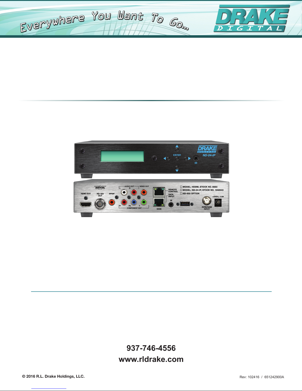
ND-24-IP
Network Decoder with HD-SDI, HDMI and Component Outputs
INSTRUCTION MANUAL
Model Item # Description
ND-24-IP 1002643 Network Decoder with SDI, HDMI and Component output
ND-RP-2 1002653 Rack Panel ND-24-IP
ND-24-Zixi-LIC 1002654 Zixi Link License Required for Point-to-Point Links
© 2016 R.L. Drake Holdings, LLC.
937-746-4556
www.rldrake.com
Rev: 102416 / 651242900A

We recommend that you write the following information in the spaces provided below.
Purchase Location Name:
Purchase Location Telephone Number:
ND-24-IP Serial Number:
This product incorporates copyright protection technology that is protected by U.S. patents and other
intellectual property rights. Reverse engineering or disassembly is prohibited.
Manual Revision
This is the first release of the instruction manual for ND-24-IP using a firmware release version of 1.0.6.
For more information regarding product firmware releases, please visit our website
at www.rldrake.com. You may also contact Technical Assistance at 937-746-6990 or
by email: servicehelp@rldrake.com
2
937.746.4556 | www.rldrake.com

Table of Contents
GENERAL & SAFETY INFORMATION
SAFETY INSTRUCTIONS & CAUTION STATEMENTS ......................................................................................................... 4
GENERAL DESCRIPTION & FEATURES ............................................................................................................................... 6
SPECIFICATIONS .................................................................................................................................................................... 7
FRONT AND REAR PANEL OPERATION .............................................................................................................................. 8
INSTALLATION & SETUP
INSTALLATION & POWER-UP ................................................................................................................................................ 9
NETWORK SETTINGS .......................................................................................................................................................... 10
LOGIN SCREEN ......................................................................................................................................................................11
UNIT CONFIGURATION
PLAYER CONTROL TAB ....................................................................................................................................................... 12
IP STREAM INPUT ................................................................................................................................................................................ 12
ZIXI PUSH INPUT .................................................................................................................................................................................. 13
DIGITAL RF CHANNEL ......................................................................................................................................................................... 14
A/V SETTINGS TAB ............................................................................................................................................................... 15
SYSTEM INFO TAB ............................................................................................................................................................... 16
LOG TAB ................................................................................................................................................................................ 17
FIRMWARE UPDATES
UPDATE TAB ......................................................................................................................................................................... 18
SERVICE & WARRANTY
SERVICE .................................................................................................................................................................................. 22
WARRANTY ............................................................................................................................................................................. 23
937.746.4556 | www.rldrake.com
3
Important Safety Instructions
1. Read Instrucons—All the safety and operang instrucons should be read before the
product is operated.
2. Retain Instrucons—The safety and operang instrucons should be retained for future
reference.
3. Heed Warnings—All warnings on the product and in the operang instrucons should be
adhered to.
4. Follow Instrucons—All operang and use instrucons should be followed.
5. Cleaning—Unplug this product from the wall outlet before cleaning. Do not use liquid
cleaners or aerosol cleansers. Use a damp cloth for cleaning.
6. Aachments—Do not use aachments that are not recommended by the product manufacturer as they may cause hazards.
7. Water and Moisture—Do not use this product near water—for example, near a bathtub,
wash bowl, kitchen sink or laundry tub; in a wet basement; or near a swimming pool; and
the like.
8. Accessories—Do not place this product on an unstable cart, stand, tripod, bracket, or
table. The product may fall, causing serious injury to a child or adult, and serious damage
to the product. Use only with a cart, stand, tripod, bracket, or table recommended by the
manufacturer, or sold with the product. Any mounng of the product should follow the
manufacturer’s instrucons, and should use a mounng accessory recommended by the
manufacturer.
9. A product and cart combinaon should be moved with care. Quick stops, excessive force,
and uneven surfaces may cause the product and cart combinaon to overturn.
10. Venlaon—Slots and openings in the cabinet are provided for venlaon and to ensure
reliable operaon of the product and to protect it from overheang, and these openings
must not be blocked or covered. The openings should never be blocked by placing the
product on a bed, sofa, rug, or similar surface. This product should not be placed in a built-in
installaon such as bookcase or rack unless proper venlaon is provided or the manufacturer’s instrucons have been adhered to.
11. Power Sources—This product should be operated only from the type of power source
indicated on the marking label. If you are not sure of the type of power supplied to your
home, consult your product dealer or local power company. For products intended to operate from baery power, or other sources, refer to the operang instrucons.
12. Grounding or Polarizaon—This product may be equipped with a polarized alternatingcurrent line plug (a plug having one blade wider than the other). This plug will t into
the power outlet only one way. This is a safety feature. If you are unable to insert the plug
fully into the outlet, try reversing the plug. If the plug should sll fail to t, contact your
electrician to replace your obsolete outlet. Do not defeat the safety purpose of the polarized
plug. Alternate Warnings—If this product is equipped with a three-wire grounding-type
plug, a plug having a third (grounding) pin, the plug will only t into a grounding-type power
outlet. This is a safety feature. If you are unable to insert the plug into the outlet, contact
your electrician to replace your obsolete outlet. Do not defeat the safety purpose of the
grounding-type plug.
13. Power-Cord Protecon—Power-supply cords should be routed so that they are not
likely to be walked on or pinched by items placed upon or against them, paying parcular
aenon to cords at plugs, convenience receptacles, and the point where they exit from the
product.
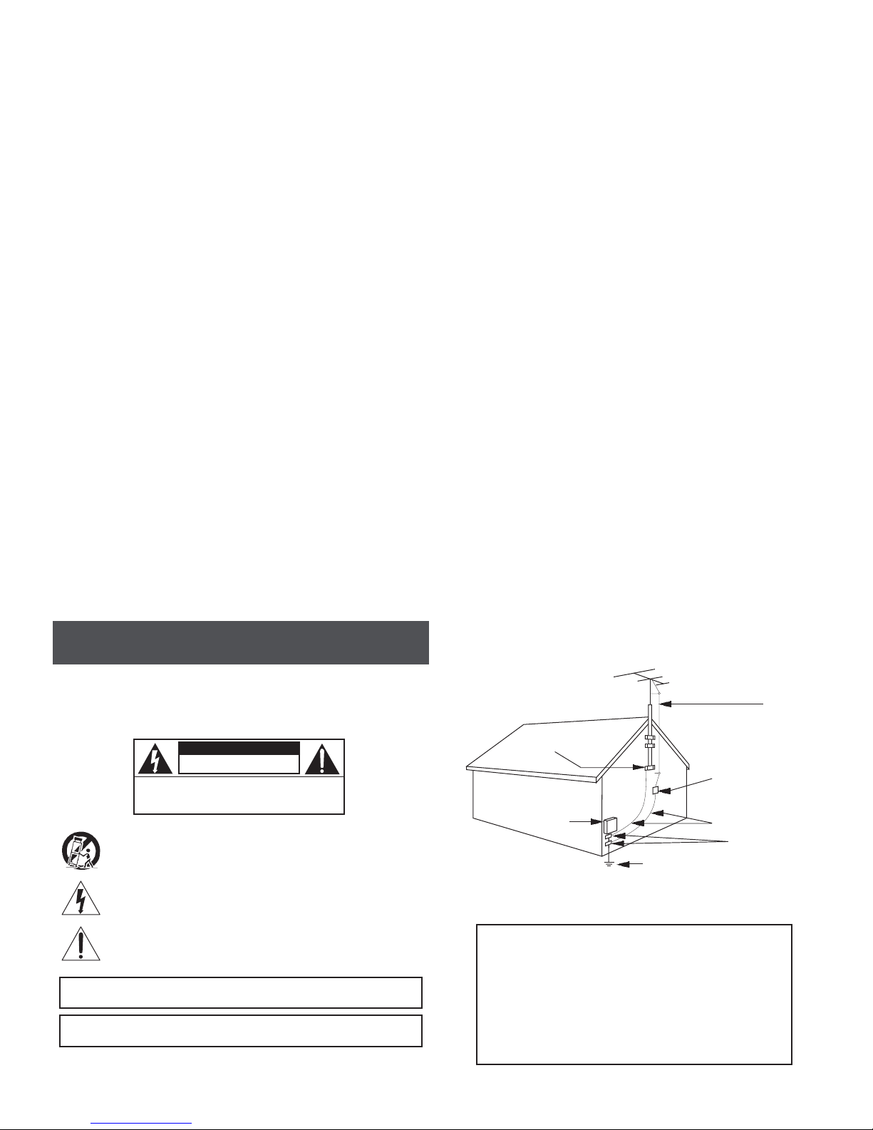
14. Outdoor Antenna Grounding—If an outside antenna or cable system is connected to the
product, be sure the antenna or cable system is grounded so as to provide some protecon
against voltage surges and built-up stac charges. Arcle 810 of the Naonal Electrical Code,
ANSI/NFPA 70, provides informaon with regard to proper grounding of the mast and supporng structure, grounding of the lead-in wire to an antenna discharge unit, size of grounding conductors, locaon of antenna-discharge unit, connecon to grounding electrodes, and
requirements for the grounding electrode. See Figure A.
15. Lightning—For added protecon for this product during a lightning storm, or when it
is le unaended and unused for long periods of me, unplug it from the wall outlet and
disconnect the antenna or cable system. This will prevent damage to the product due to
lightning and power-line surges.
16. Power Lines—An outside antenna system should not be located in the vicinity of overhead power lines, other electric light or power circuits, where it can fall into such power lines
or circuits.
17. Overloading—Do not overload wall outlets, extension cords, or integral convenience
receptacles as this can result in a risk of re or electric shock.
18. Object and Liquid Entry—Never push objects of any kind into this product through openings as they may touch dangerous voltage points or short-out parts that could result in a re
or electric shock. Never spill liquid of any kind on the product.
19. Servicing—Do not aempt to service this product yourself as opening or removing covers may expose you to dangerous voltage or other hazards. Refer all servicing to qualied
service personnel.
20. Damage Requiring Service—Unplug this product from the wall outlet and refer servicing
to qualied service personnel under the following condions:
a. When the power-supply cord or plug is damaged,
b. If liquid has been spilled, or objects have fallen into the product,
c. If the product has been exposed to rain or water,
d. If the product does not operate normally by following the operang instrucons. Adjust
only those controls that are covered by the operang instrucons as an improper adjustment of other controls may result in damage and will oen require extensive work by a
qualied technician to restore the product to its normal operaon,
e. If the product has been dropped or damaged in any way, and
f. When the product exhibits a disnct change in performance—this indicates a need for
service.
21. Replacement Parts—When replacement parts are required, be sure the service technician has used replacement parts specied by the manufacturer or have the same characteriscs as the original part. Unauthorized substutes may result in re, electric shock or other
hazards.
22. Safety Check—Upon compleon of any service or repairs to this product, ask the service
technician to perform safety checks to determine that the product is in proper operang
condion.
23. Wall or Ceiling Mounng—The product should be mounted to a wall or ceiling only as
recommended by the manufacturer.
24. Heat—The product should be situated away from heat sources such as radiators, heat
registers, stoves, or other products (including ampliers) that produce heat.
CAUTION STATEMENT
WARNING: TO PREVENT FIRE OR
ELECTRICAL SHOCK DO NOT
EXPOSE TO RAIN OR MOISTURE
! CAUTION !
RISK OF ELECTRIC SHOCK
DO NOT OPEN
WARNING: TO REDUCE THE RISK OF ELECTRIC SHOCK, DO NOT
An appliance and cart combinaon should be moved with care. Quick stops, excessive
force and uneven surfaces may cause the appliance and cart combinaon to overturn.
The lightning ash with arrow head symbol, within an equilateral triangle, is intended to
alert the user to the presence of uninsulated “dangerous voltage” within the product’s
enclosure that may be of sucient magnitude to constute a risk of electric shock to
persons.
The exclamaon point within an equilateral triangle is intended to alert the user to
the presence of important operang and maintenance (servicing) instrucons in the
literature accompanying the appliance.
WARNING:
CAUTION:
REMOVE POWER SUPPLY COVERS
NO USER-SERVICEABLE PARTS INSIDE
REFER SERVICING TO QUALIFIED PERSONNEL
TO REDUCE THE RISK OF FIRE OR ELECTRIC SHOCK, DO NOT EXPOSE THIS
APPLIANCE TO RAIN OR MOISTURE. DO NOT OPEN THE CABINET, REFER
SERVICING TO QUALIFIED PERSONNEL ONLY.
TO PREVENT ELECTRIC SHOCK, DO NOT USE THIS (POLARIZED) PLUG WITH AN
EXTENSION CORD RECEPTACLE OR OTHER OUTLET UNLESS THE BLADES CAN
BE FULLY INSERTED TO PREVENT BLADE EXPOSURE.
Example of antenna grounding as per Naonal Electrical Code, ANSI/NFPA 70
FIGURE A
GROUND CLAMP
ELECTRIC
SERVICE
EQUIPMENT
POWER SERVICE GROUNDING ELECTRODE
SYSTEM (NEC ART 250, PART H)
NEC - NATIONAL ELECTRIC CODE
NOTE TO CATV SYSTEM INSTALLERS:
THIS REMINDER IS PROVIDED TO CALL THE CATV
SYSTEM INSTALLER’S ATTENTION TO ARTICLE 820 - 40
OF THE NEC WHICH PROVIDES GUIDELINES FOR PROPER
GROUNDING AND, IN PARTICULAR, SPECIFIES THAT
THE CABLE GROUND SHALL BE CONNECTED TO THE
GROUNDING SYSTEM OF THE BUILDING, AS CLOSE TO
THE POINT OF CABLE ENTRY AS PRACTICAL.
ANTENNA
DISCHARGE UNIT
(NEC SECTION 810-20)
GROUNDING
CONDUCTORS
(NEC SECTION 810-21)
GROUND CLAMPS
ANTENNA
LEAD IN
WIRE
4
937.746.4556 | www.rldrake.com
Importantes De Sécurité
1. Lire les direcves—Toutes les direcves de sécurité et d’ulisaon devraient être lues
avant de mere l’appareil en opéraon.
2. Conserver les direcves—Les direcves de sécurité et d’ulisaon devraient être conservées pour consultaon future.
3. Tenir compte des averssements—Tous les averssements apparaissant sur l’appareil et
dans les consignes d’ulisaon devraient être respectés.
4. Suivre les direcves—Toutes les direcves d’opéraon et d’ulisaon devraient être
suivies.
5. Neoyage—Débrancher l’appareil de la prise électrique murale avant le neoyage. Ne pas
uliser de neoyants liquides ou aérosols. Employer un linge humide pour le neoyage.
6. Fixaon—Ne pas uliser d’autres xaons que celles recommandées par le manufacturier;
elles pourraient être source de dangers.
7. Eau et humidité—Ne pas uliser cet appareil près de l’eau. Par exemple, près d’une
baignoire, d’un bac de lavage, d’un évier de cuisine ou d’une cuvee de lessivage; dans un
sous-sol humide; ou à proximité d’une piscine; et autres environnements similaires.
8. Accessoires—Ne pas installer cet appareil sur un chariot, un socle, un trépied, un support
ou une table instables. L’appareil pourrait tomber, entraînant des blessures graves à un
enfant ou à un adulte, et des dommages importants à l’appareil. Employer seulement avec
un chariot, un socle, un trépied, un support, ou une table recommandés par le fabricant ou
vendu avec l’appareil. Toute installaon de l’appareil devrait être conforme aux direcves du
manufacturier et devrait uliser des accessoires d’installaon recommandés par celui-ci.
9. Un chariot supportant l’appareil devrait être déplacé avec précauon. Les arrêts brusques,
la force excessive et les surfaces inégales peuvent renverser le chariot.
10. Venlaon—Des fentes et ouvertures dans le châssis sont prévues pour la venlaon
de l’appareil, pour en assurer la abilité d’opéraon et le protéger contre la surchaue.
Ces ouvertures ne doivent pas être bloquées ou recouvertes. Ces ouvertures ne devraient
jamais être bloquées en plaçant l’appareil sur un lit, un sofa, une couverture, ou une surface
semblable. Cet appareil ne devrait pas être installé dans un meuble encastré comme une bibliothèque ou une étagère à moins de lui fournir une venlaon adéquate ou que l’installaon
soit conforme aux direcves du manufacturier.
11. Sources d’alimentaon électrique—Cet appareil devrait être ulisé seulement avec
le type d’alimentaon électrique inscrite sur l’équee. Si vous n’êtes pas certain du type
d’alimentaon électrique fourni à votre maison, consultez le vendeur de l’appareil ou
l’entreprises d’énergie locale. Pour des appareils alimentés par une baerie ou d’autres
sources, se référer aux consignes d’ulisaon.
12. Mise à la terre ou Polarisaon—Cet appareil est équipé avec un cordon d’alimentaon
à trois ls. Il est a brancher sur une prise ayant un connecteur a la terre. Assurez-vous que la
connecon a la terre ne manque pas.
13. Protecon du cordon d’alimentaon—Les cordons d’alimentaon devraient être disposés de façon à ce qu’on ne puisse marcher dessus ou qu’ils soient suscepbles d’être coincés
par des arcles placés sur ou contre eux. Une aenon parculière doit être portée aux
ches, prises de courant, et aux points où ils sortent de l’appareil.
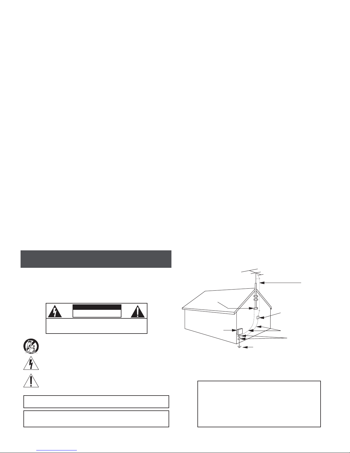
14. Mise à la terre de l’antenne extérieure—Si un système extérieur d’antenne ou de câble
est relié à l’appareil, s’assurer que le système d’antenne ou de câble est muni d’une mise à la
terre an de fournir une certaine protecon contre les surtensions et les charges d’électricité
staque. L’arcle 810 du code électrique naonal, ANSI/NFPA 70, fournit l’informaon nécessaire en ce qui concerne la mise à la terre appropriée du mât et de la structure porteuse,
la mise à la terre du câble de connexion à une unité de décharge d’antenne, le calibre des
conducteurs de mise à la terre, la locaon de l’unité de décharge d’antenne, le raccordement
aux électrodes de mise à la terre et les spécicaons pour les électrodes de mise à la terre.
Voir la gure A.
15. Foudre—Pour une protecon supplémentaire de cet appareil pendant un orage électrique, ou quand il est laissé sans surveillance et inulisé pendant de longues périodes, le
débrancher de la prise électrique murale et déconnecter le système d’antenne ou de câble.
Ceci préviendra les dommages à l’appareil dus à la foudre et aux surtensions.
16. Lignes électriques—Un système d’antenne extérieur ne devrait pas être situé à proximité
de lignes électriques aériennes ou de tout autre circuit électrique, où il pourrait tomber sur
de tels circuits ou lignes électriques. Lors de l’installaon d’un système d’antenne extérieur,
d’extrêmes précauons devraient être prises an de prévenir tout contact avec des lignes ou
circuits électriques. Entrer en contact avec de tels circuits ou lignes électriques pourrait être
fatal.
17. Surcharge—Ne pas surcharger les prises de courant murales, les rallonges électriques ou
les prises de courant intégrées. Un risque d’incendie ou de choc électrique pourrait résulter
d’une telle surcharge.
18. Inseron d’objet ou de liquide—Ne jamais insérer d’objet par les ouvertures de cet
appareil. Il pourrait toucher des points de voltage dangereux ou court-circuiter des pièces,
ce qui pourrait résulter en incendie ou en choc électrique. Ne jamais verser de liquide sur
l’appareil.
19. Entreen—Ne pas essayer de faire soi-même l’entreen de cet appareil. En ouvrir ou en
rerer les couvercles pourrait vous exposer à des voltages dangereux ou à d’autres dangers.
Coner tout entreen à un personnel de service qualié.
20. Dommage exigeant un entreen—Débrancher cet appareil de la prise de courant électrique et coner l’entreen au personnel de service qualié dans les éventualités suivantes:
a. Quand le cordon d’alimentaon ou sa che sont endommagés,
b. Si des objets sont tombés dans l’appareil, ou si du liquide y a été renversé,
c. Si l’appareil a été exposé à la pluie ou à l’eau,
d. Si l’appareil ne fonconne pas normalement en suivant les consignes d’ulisaon.
Ajuster seulement les commandes qui sont menonnées dans le guide d’opéraon. Un
mauvais ajustement des autres commandes pourrait causer des dommages à l’appareil et
souvent exiger un travail supplémentaire de la part d’un technicien qualié pour remere
l’appareil en état normal d’opéraon.
e. Si l’appareil a été échappé ou endommagé de n’importe quelle façon, et
f. Quand l’appareil montre un changement notable de performance – ceci indique qu’un
entreen est nécessaire.
21. Pièces de rechange—Si des pièces de rechange sont nécessaires, s’assurer que le technicien de service a employé des pièces de rechange spéciques du manufacturier ou ayant
les mêmes caractérisques que les pièces originales. L’ulisaon de pièces de rechange non
autorisées pourrait résulter en incendie, choc électrique ou autres dangers.
22. Véricaon de sécurité—À la suite de toute réparaon ou entreen de cet appareil,
demander au technicien de service d’exécuter des véricaons de sécurité an de s’assurer
que l’appareil est en condion normale de fonconnement.
23. Montage au mur ou au plafond—L’appareil ne devrait être monté au mur ou au plafond
qu’uniquement de la façon recommandée par le manufacturier.
24. Chaleur—L’appareil devrait être situé loin de sources de chaleur telles que des radiateurs, des registres de chaleur, des fourneaux, ou d’autres appareils (y compris amplicateurs) produisant de la chaleur.
ATTENTION DÉCLARATION
AVERTISSEMENT: AFIN D’ÉVITER TOUT RISQUE D’INCENDIE
OU D’ÉLECTROCUTION, NE PAS EXPOSER CET APPAREIL À LA
PLUIE OU À L’HUMIDITÉ.
! AVERTISSEMENT !
RISQUE DE CHOC ELECTRIQUE -
NE PAS OUVRIR
ATTENTION: POUR RÉDUIRE LE RISQUE D’ÉLECTROCUTION, NE PAS
ENLEVER LE DOS DE L’APPAREIL NI OUVRIR LE BOÎTIER. AUCUNE PIÈCE N’EST
RÉPARABLE PAR L’UTILISATEUR À L’INTÉRIEUR. SE RÉFÉRER UNIQUEMENT À
DES TECHNICIENS QUALIFIÉS POUR L’ENTRETIEN.
Une combinaison de l’appareil et chariot doit être déplacé avec précauon. Des arrêts
brusques, une force excessive et des surfaces inégales peuvent causer la combinaison
de l’appareil et le chariot.
Le symbole de l’éclair à l’intérieur d’un triangle équilatéral est desné à alerter
l’ulisateur sur la présence d’une “tension dangereuse” non isolée dans le boîer du
produit. cee tension est susante pour provoquer l’électrocuon de personnes.
Le point d’exclamaon à l’intérieur d’un triangle équilatéral est desné à alerter
l’ulisateur sur la présence d’opéraons d’entreen importantes au sujet desquelles des
renseignements se trouvent dans le manuel d’instrucons.
AVERTISSEMENT:
CAUTION:
AFIN D’ÉVITER TOUT RISQUE D’INCENDIE OU D’ÉLECTROCUTION, NE PAS
EXPOSER CET APPAREIL À LA PLUIE OU À L’HUMIDITÉ. NE PAS OUVRIR LE
BOÎTIER, CONFIER TOUS TRAVAUX À DU PERSONNEL TECHNIQUE QUALIFIÉ.
POUR PREVENIR LES CHOCS ELECTRIQUES, NE PAS UTILISER CETTE FICHE
POLARISEE AVEC UN PROLONGATEUR, UNE PRISE DE COURANT OU UNE
AUTRE SORTIE DE COURANT, SAUF SI LES LAMES PEUVENT ETRE INSEREES A
FOND SANS EN LAISSER AUCUNE PARTIE A DECOUVERT.
Exemple de mise à la terre d’antenne selon le Code Électrique Naonal, ANSI/NFPA 70
FIGURE A
ANTENNA
LEAD IN
WIRE
ATTACHES DE
MISE À LA TERRE
UNITÉ DE DÉCHARCHE D’ANTENNE
(NEC SECTION 810-20)
APPAREILS
ÉLECTRIQUES
DE SERVICE
NEC - CODE ÉLECTRIQUE NATIONAL
NOTE AUX INSTALLATEURS DE SYSTÈME DE CATV:
CE RAPPEL EST FOURNI POUR PORTER À L’ATTENTION DES
INSTALLATEURS DE SYSTÈME DE CATV, L’ARTICLE 820 - 40 DU
NEC QUI DONNE DES DIRECTIVES POUR UNE MISE À LA TERRE
APPROPRIÉE ET, EN PARTICULIER, SPÉCIFIE QUE LE CÂBLE DE
MISE À LA TERRE DEVRAIT ÊTRE RACCORDÉ AU SYSTÈME DE
MISE À LA TERRE DU BÂTIMENT LE PLUS PRÈS POSSIBLE DE
L’ENTRÉE DU CÂBLE.
SYSTÈME DE MISE À LA TERRE DU BÂTIMENT
CONDUCTEURS DE MISE À LA TERRE
(NEC SECTION 810-21)
ATTACHES DE
MISE À LA TERRE
(NEC ART 250, PART H)
937.746.4556 | www.rldrake.com
5

General Description & Features
INTRODUCTION
The ND-24-IP is a low cost professional MPEG-2 and H.264 decoder that is capable of receiving
content from off-air, clear QAM, and IP sources. The ND-24-IP is capable of outputting simultaneously
video content in SDI, HDMI and component formats. SDI outputs are available in 3G-SDI, HD-SDI, or
SD-SDI formats.
The unit can be used as a stand-alone high quality decoder, or used in conjunction with other IP
encoders, to provide an end-to-end IP video delivery solution over a managed network.
When the ND-24-IP decoder is used with Drake’s PEG encoder (PEG-NE24-IP-CZ), along with a Zixi
Link license it can provide a point to point reliable IP video transport from anywhere in the world with
an internet connection. The ND-24-IP can also be used in a point to multipoint application, where the
ND-24-IP would decode the IP based Zixi protocol stream from a Zixi Broadcaster.
The ND-24-IP features a Liquid Crystal Display (LCD) for front panel setup and easy to use management
controls through IR, expansion port or an IP web-based GUI.
FEATURES
• Simultaneous SDI/HDMI/Component HD + Composite SD Outputs
• Decoding content from Off-Air, Clear QAM, and IP sources
• Supports both MPEG-2 and H.264 content
• LCD screen
• Closed Captioning
• VBR or CBR
• IGMPv2 and IGMPv3
• Pass-through of dolby encoded embedded audio (Future rmware release)
6
937.746.4556 | www.rldrake.com
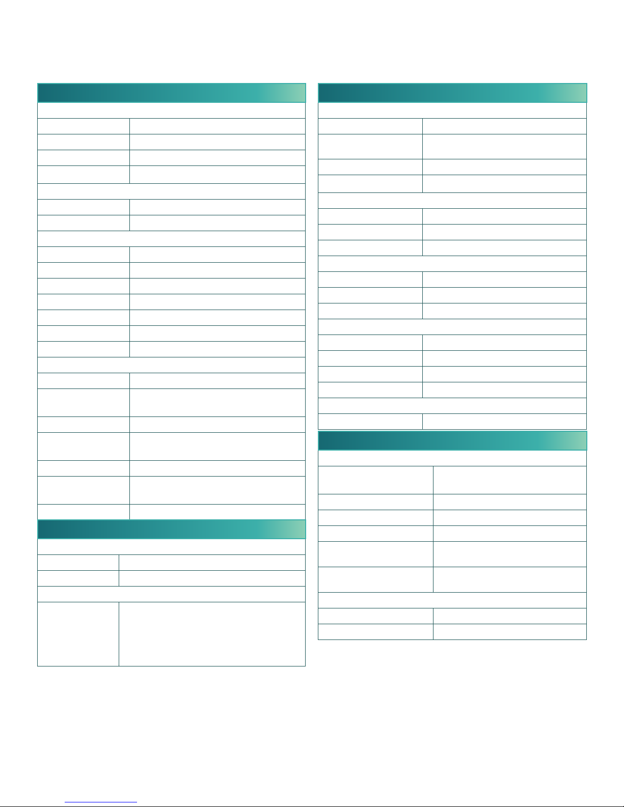
Specifications
ND-24-IP Network Decoder with HD-SDI, HDMI and Component outputs Item # 1002643
INPUT
IP Mode
Connectors: RJ-45
Standard: 100/1000Base-T Ethernet
UDP/RTP: Supported
Protocols: IGMPv3/IGMPv2 Supported
Stream Porolio
SPTS and MPTS: Null Packet Deleon
Bit Rate: Variable and Constant
8VSB Mode
Connectors: 1x “F” Female
Standard: ATSC Digital Television A/53E
Tuning Range: UHF (Ch.14-69), VHF (Ch.2-13)
Data Rate: 19.392 MHz
Bandwidth: 6 MHz
Power Level: -20 to +20 dBmV
Impedance: 75 Ω
QAM Mode
Connectors: 1x “F” Female
Standard: ITU-T J.83; Annex A and B
(64 & 256 QAM)
Tuning Range: CATV Ch. 2-158 (STD, HRC, IRC)
Data Range: 38.8 Mbps (QAM 256);
26.97 Mbps (QAM 64) – Auto Detect
Bandwidth: 6 MHz
Power Level: -15 to 20 dBmV (@ QAM 256),
-20 to 20 dBmV (@ QAM 64)
Impedance: 75 Ω
ALARMS/MONITORING/CONTROL
Local
Monitoring: Front-panel LCD screen
Control: Front-panel Navigaonal Key-pad
Remote
Monitoring/
Control:
GUI-based menu via Web browser
(1x RJ45 rear-panel connector; 10/100Base-T)
Expansion Port for RS-232 Control
(Requires Opt. Adapter Cable #6671)
IR input: 3.5 mm stereo input for external
IR remote
OUTPUT
3G/HD/SD-SDI
Connectors: 1x BNC
Standards: SMPTE 259M (3G), SMPTE 292 (HD)
& SMPTE 259M (SD)
Video Resoluon: 480i, 720p, 1080i, & 1080p
Audio: Embedded PCM
HDMI
Connectors: 1x HDMI
Video Resoluon: 480i, 720p, 1080i, & 1080p
Audio: Embedded PCM
Composite
Connectors: 1x RCA for Video
Video Resoluon: 480i
Audio: 2x RCA for Analog Audio (L,R)
Component
Connectors: 3x RCA for Video (Y, Pb, Pr)
Video Resoluon: 480i, 720p, & 1080i
Video Aspect Rao: 4:3 & 16:9
Audio: 2x RCA for Analog Audio (L,R)
Digital Audio (SPDIF)
Connectors: 1x RCA
GENERAL
Mechanical
Dimensions: 8.69 x 8.0 x 1.97 inches
(220.7 x 203 x 50.0 mm)
Weight: 3.0 lbs (1.36 kg)
Operang Temperature: 32 to 122 °F (0 to 50 °C)
Storage Temperature: -13 to 158 °F (-25 to 70 °C)
Operang Humidity: 0 to 95% RH @ 35 °C max,
non-condensing
Storage Humidity: 0 to 95% RH @ 35 °C max,
non-condensing
Power
Power: 5 VDC External Power Supply
Dissipaon: 10 W
Specicaons are subject to change without noce or obligaon.
937.746.4556 | www.rldrake.com
7
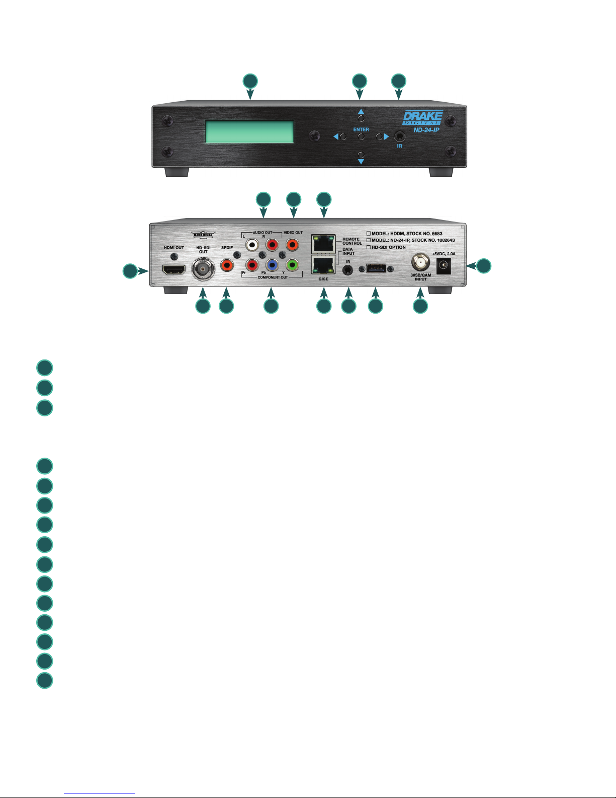
Front and Rear Panel Operation
1 2 3
7 8
4
5 6 9
FRONT PANEL
1
LCD Display: used for Network Settings
2
Controls: used for Network Settings
Infared Remote Control: not supported with firmware release v1.0.6
3
REAR PANEL
4
HDMI Out: HDMI A/V Output
5
HD-SDI Out: HD/SD SDI Output *
(1)
10
15
11 12 13 14
6
SPDIF: S/PDIF Digital Audio Output
7
Audio Out: Analog L+R Audio Output
8
Video Out: Composite Analog Video Output *
9
Component Out: Component Video Output
10
Remote Control: GigE Ethernet Port for User Interface
11
Data Input: GigE Ethernet Port for IP Input
12
IR: IR extender, not supported with firmware release v1.0.6
13
USB: USB Service Port
14
8VSB/QAM Input: Digital Tuner Input
15
+5VDC, 2.0A: DC supplied from included AC adapter.
*(1) Note - Current rmware allows for SD-SDI or composite video. When the video resolution is 480i and SD-SDI
is set to "Enable", you'll get SD-SDI, but NOT composite. If SD-SDI is set to "Disable", you'll get composite, but
not SD-SDI. If the video resolution is anything other than 480i, this has no effect.
8
937.746.4556 | www.rldrake.com
(1)
 Loading...