

Page 1
MQM6000L Multiplexing QAM Modulator
Instruction Manual
is a registered trademark of the R.L. Drake Holdings, LLC
© Copyright 2012 R. L. Drake Holdings, LLC P/N: 651227900A Printed in U.S.A.
Rev: 20120720
1002505
Page 2

2
Table of Contents, Caution, & Important Safety Instructions
CAUTION STATEMENTS .....................................................................................................................................2
IMPORTANT SAFETY INSTRUCTIONS ..............................................................................................................2
SPECIFICATIONS ................................................................................................................................................4
GENERAL DESCRIPTION ...................................................................................................................................5
INSTALLATION / FRONT PANEL CONTROLS .....................................................................................................6
REAR PANEL CONNECTIONS ............................................................................................................................7
SETUP AND PROGRAMMING .............................................................................................................................8
OPERATION ........................................................................................................................................................10
ADDITIONAL INFORMATION .............................................................................................................................11
BROADCAST TV CHANNEL FREQUENCIES ...................................................................................................12
SERVICE / IF YOU NEED TO CALL FOR HELP .................................................................................................14
WARRANTY .........................................................................................................................................................16
Caution Statements:
WARNING: TO PREVENT FIRE OR
ELECTRICAL SHOCK, DO NOT
EXPOSE TO RAIN OR MOISTURE
WARNING: TO REDUCE THE RISK OF FIRE OR ELECTRIC SHOCK, DO NOT EXPOSE THIS PRODUCT TO
RAIN OR MOISTURE.
DO NOT OPEN THE CABINET, REFER SERVICING TO QUALIFIED PERSONNEL ONLY.
CAUTION: TO PREVENT ELECTRIC SHOCK, DO NOT USE THIS (POLARIZED) PLUG WITH AN EXTENSION
CORD RECEPTACLE OR OTHER OUTLET UNLESS THE BLADES CAN BE FULLY INSERTED TO
PREVENT BLADE EXPOSURE.
A product and cart combination should be moved
with care. Quick stops, excessive force and uneven
surfaces may cause the product and cart combination
to overturn.
The lightning flash with arrow head symbol, within an
equilateral triangle, is intended to alert the user to the
presence of uninsulated "dangerous voltage" within
the product's enclosure that may be of sufficient
magnitude to constitute a risk of electric shock to
persons.
The exclamation point within an equilateral triangle is
intended to alert the user to the presence of important
operating and maintenance (servicing) instructions in
the literature accompanying the product.
ATTENTION: POUR PREVENIR LES CHOCS ELECTRIQUES, NE PAS UTILISER CETTE FICHE POLARISEE
AVEC UN PROLONGATEUR, UNE PRISE DE COURANT OU UNE AUTRE SORTIE DE COURANT,
SAUF SI LES LAMES PEUVENT ETRE INSEREES A FOND SANS EN LAISSER AUCUNE PARTIE A
DECOUVERT.
Important Safety Instructions:
1. Read Instructions: All the safety and operating instructions should be read before the product is operated.
2. Retain Instructions: The safety and operating instructions should be retained for future reference.
3. Heed Warnings: All warnings on the product and in the operating instructions should be adhered to.
4. Follow Instructions: All operating and use instructions should be followed.
5. Cleaning: Unplug this product from the wall outlet before cleaning. Do not use liquid cleaners or aerosol cleansers. Use a damp cloth for cleaning.
6. Attachments: Do not use attachments that are not recommended by the product manufacturer as they may cause hazards.
7. Water and Moisture: Do not use this product near water—for example, near a bathtub, wash bowl, kitchen sink or laundry tub; in a wet basement;
or near a swimming pool; and the like.
Page 3
3Important Safety Instructions (continued)
8. Accessories: Do not place this product on an unstable cart, stand, tripod, bracket, or table. The product may fall, causing serious injury to a child
or adult, and serious damage to the product. Use only with a cart, stand, tripod, bracket, or table recommended by the manufacturer, or sold with
the product. Any mounting of the product should follow the manufacturer's instructions, and should use a mounting accessory recommended by the
manufacturer.
9. A product and cart combination should be moved with care. Quick stops, excessive force, and uneven surfaces may cause the product and cart
combination to overturn.
10. Ventilation: Slots and openings in the cabinet are provided for ventilation and to ensure reliable operation of the product and to protect it from
overheating, and these openings must not be blocked or covered. The openings should never be blocked by placing the product on a bed, sofa, rug,
or similar surface. This product should not be placed in a built-in installation such as bookcase or rack unless proper ventilation is provided or the
manufacturer's instructions have been adhered to.
11. Power Sources: This product should be operated only from the type of power source indicated on the marking label. If you are not sure of the type
of power supplied to your home, consult your product dealer or local power company. For products intended to operate from battery power, or other
sources, refer to the operating instructions.
12. Grounding or Polarization: This product may be equipped with a polarized alternating-current line plug (a plug having one blade wider than the
other). This plug will fit into the power outlet only one way. This is a safety feature. If you are unable to insert the plug fully into the outlet, try reversing
the plug. If the plug should still fail to fit, contact your electrician to replace your obsolete outlet. Do not defeat the safety purpose of the polarized
plug. Alternate Warnings – If this product is equipped with a three-wire grounding- type plug, a plug having a third (grounding) pin, the plug will only fit
into a grounding-type power outlet. This is a safety feature. If you are unable to insert the plug into the outlet, contact your electrician to replace your
obsolete outlet. Do not defeat the safety purpose of the grounding-type plug.
13. Mise à la terre ou Polarisation: Cet appareil est équipé avec un cordon d'alimentation à trois fils. Il est a brancher sur une prise ayant un connecteur
a la terre. Assurez-vous que la connection a la terre ne manque pas.
14. Power-Cord Protection: Power-supply cords should be routed so that they are not likely to be walked on or pinched by items placed upon or against
them, paying particular attention to cords at plugs, convenience receptacles, and the point where they exit from the product.
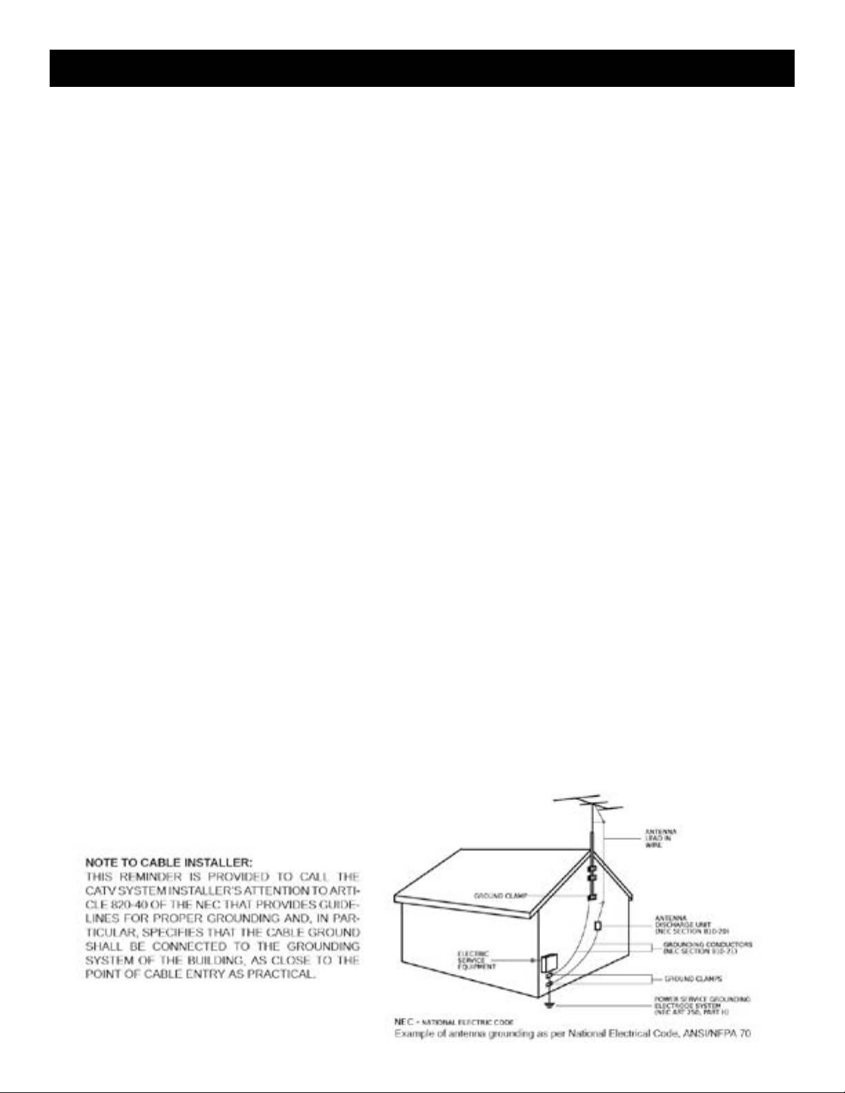
15. Lightning: For added protection for this product during a lightning storm, or when it is left unattended and unused for long periods of time, unplug it
from the wall outlet and disconnect the antenna or cable system. This will prevent damage to the product due to lightning and power-line surges.
16. Power Lines: An outside antenna system should not be located in the vicinity of overhead power lines, other electric light or power circuits, where it
can fall into such power lines or circuits. When installing an outside antenna system, extreme care should be taken to keep from touching such power
lines or circuits as contact with them may be fatal.
17. Overloading: Do not overload wall outlets, extension cords, or integral convenience receptacles as this can result in a risk of fire or electric shock.
18. Object and Liquid Entry: Never push objects of any kind into this product through openings as they may touch dangerous voltage points or short-out
parts that could result in a fire or electric shock. Never spill liquid of any kind on the product.
19. Servicing: Do not attempt to service this product yourself as opening or removing covers may expose you to dangerous voltage or other hazards.
Refer all servicing to qualified service personnel.
20. Damage Requiring Service: Unplug this product from the wall outlet and refer servicing to qualified service personnel under the following conditions:
a) When the power-supply cord or plug is damaged,
b) If liquid has been spilled, or objects have fallen into the product,
c) If the product has been exposed to rain or water,
d) If the product does not operate normally by following the operating instructions.
Adjust only those controls that are covered by the operating instructions as an improper adjustment of other controls may result in damage and will
often require extensive work by a qualified technician to restore the product to its normal operation, e. If the product has been dropped or damaged
in any way, and f. When the product exhibits a distinct change in performance—this indicates a need for service.
21. Replacement Parts: When replacement parts are required, be sure the service technician has used replacement parts specified by the manufacturer
or have the same characteristics as the original part. Unauthorized substitutes may result in fire, electric shock or other hazards.
22. Safety Check: Upon completion of any service or repairs to this product, ask the service technician to perform safety checks to determine that the
product is in proper operating condition.
23. Wall or Ceiling Mounting: The product should be mounted to a wall or ceiling only as recommended by the manufacturer.
24. Heat: The product should be situated away from heat sources such as radiators, heat registers, stoves, or other products (including amplifiers) that
produce heat.
Page 4
4
Specications
ASI INPUTS
Six Inputs: 270 MHz clock rate, 40 Mbps maximum TS rate at each input.
Programs: MPTS or SPTS
Multiplexing and Program Filter: One SPTS may be selected from each input. The selected programs will be multiplexed as long
Null Packet Processing: Fixed output clock mode
QAM MODULATOR
Modulation Modes: 16QAM, 32QAM, 64QAM, 128QAM, 256QAM, 512QAM or 1024QAM. (See page 9 for all available
Symbol Rate: 1 Ms/s to 7 Ms/s.
I/Q Phase Error: Less than 1 degree.
Carrier Suppression: 45 dB.
Channel Amplitude Error: Less than 1 dB.
UPCONVERTER RF OUTPUT
Output Frequency Range: 54 MHz to 1002 MHz.
Channel Plan: Std. CATV, HRC, IRC, or Broadcast
FCC offsets: Automatic, +12.5 or +25 kHz
Frequency Stability: ± 5 ppm.
Maximum Output Level: + 40 dBmV minimum, adjustable downward.
Output Level Accuracy: ± 1 dB.
Output Impedance: 75 Ohms with return loss better than 14 dB (within output lter passband).
Spurious Outputs: -60 dBc from 40 MHz to 1000 MHz.
Broadband Noise: -75 dBc
Phase Noise: -101 dBc @ 10 kHz offset
as the data rate of the resulting MPTS does not exceed the output QAM channel capacity.
combinations of QAM modes and FEC.)
FEC: ITUA (DVB) or ITUB (DigiCipher II).
MER: Greater than 38 dB with blind equalizer.
RS232 CONTROL
Data Link: 2400, 4800, 9600, or 19,200 baud interface via serial cable.
RS232 Input: DB-9 connector for connection to modem or PC.
RS232 Output: DB-9 connector for connection to additional transcoders.
GENERAL
Power: 90 - 132 VAC/ 60 Hz, 15 W maximum.
Weight: 7 pounds
Size: 19” W x 1.75” H x 11.5” D.
Operating Temperature: 0 degrees C to + 50 degrees C
Specifications subject to change without notice or obligation.
Page 5
5General Description
General Description
The R.L. Drake model MQM6000L is a professional quality, digital headend transcoder that receives up to six
multiprogram transport streams via six BNC, ASI inputs. When six streams are input, the MQM6000L then
multiplexes one program from each input and applies the result to the QAM modulator and up converter for
output.
A program filter is provided to allow selection of the one desired program from each input. Other programs in the
incoming streams are dropped.
The MQM6000L offers a +40 dBmV output upconverter with phase noise reduced to a level that is compatible
with QAM modes up through 1024QAM.
The MQM6000L can be used with the Drake Digital Headend Remote Control Software, version to be announced,
for setting up the program filtering, remote controlling, or remote monitoring of operating parameters. This
program can also be used to download new firmware into the unit if that ever becomes desirable. The MQM6000L
operates in a fixed output clock mode and processes null packets when required to maintain the set fixed clock
rate. PCR correction is included.
PROGRAM FILTERING
A 'Select Program' function is provided to allow the operator to select which MPEG program present on each of the
six input streams is to be included in the output multiplex.
OUTPUT
The RF output is always QAM regardless of whether the input is VSB or QAM and the built-in agile upconverter
provides +40 dBmV output.
Page 6
6
Installation & Mounting / Front Panel Controls
INSTALLATION AND MOUNTING NOTES
This equipment is designed to be installed in a standard 19” rack. When the unit is mounted above or below other
rack mounted equipment, a 1U space should be left between the unit and the other equipment to allow ambient
air flow between the units.
Connect the AC line cord to an appropriate source of 120 volt, 50/60 Hz AC power. The MQM6000L is always on
once the AC power cord is connected to its power source.
Front Panel Controls
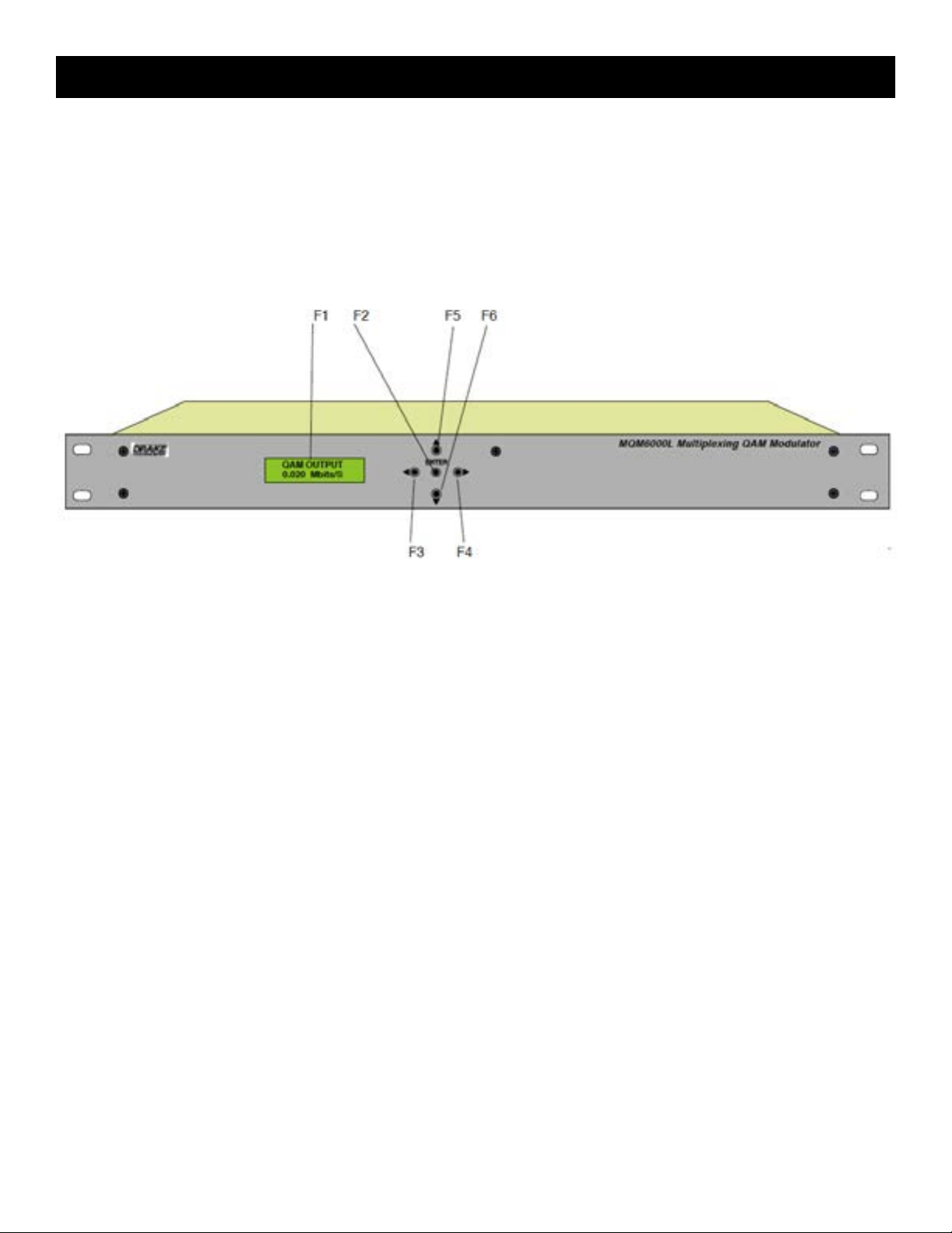
F1, LCD Display – This display presents the selected menu screen and the parameter settings. The backlight
in the display is on when power is applied. When not in adjust mode the QAM output symbol rate in Mbits
per second is displayed. Pressing the down button shows the buffer status as a percentage of its maximum
capacity. The left percentage represents the current buffer status and the right number represents the maximum
percentage of buffer capacity that was reached since the unit was last programmed. If either of these numbers
reaches 100%, it is probable that too much data is being processed which will likely result in missed frames, video
or audio breakup, or other anomalies in the output signal.
Repeatedly pressing the down button will toggle back and forth between the buffer status screen and the QAM
output symbol rate screen. Pressing the up button causes the display to show the firmware version number.
Repeatedly pressing the up button will cause the display to toggle back and forth between the firmware version
number and either the QAM output symbol rate screen or the buffer status screen, which ever one is selected
with the down button.
F2, ENTER button – Use the ENTER button to enter the adjust mode or to save and load a new setting or settings
after adjustment. Hold for 2 seconds until the bottom line of the display starts to flash to enter the adjust mode. After
entering the adjust mode, momentarily pressing the ENTER button again will load and save any settings that may
have been changed using the F5 & F6 buttons.
F3 & F4, Left and Right Buttons – Use the left and right arrow buttons to navigate from screen to screen to view
a parameter setting. These buttons are operational in the view mode or the adjust mode. Using only these buttons
will not change any parameter settings. After a short period of button inactivity, the default display will be returned.
F5 & F6, Up and Down Buttons – Use the up and down arrow buttons to change the value of a viewed parameter
setting. The unit must be in the adjust mode with the display flashing in order for these buttons to become active for
changing a parameter setting. If the unit is not in the adjust mode, pressing the up button will display the firmware
version number or pressing the down button will display the output QAM symbol rate.
Page 7

Rear Panel Connections
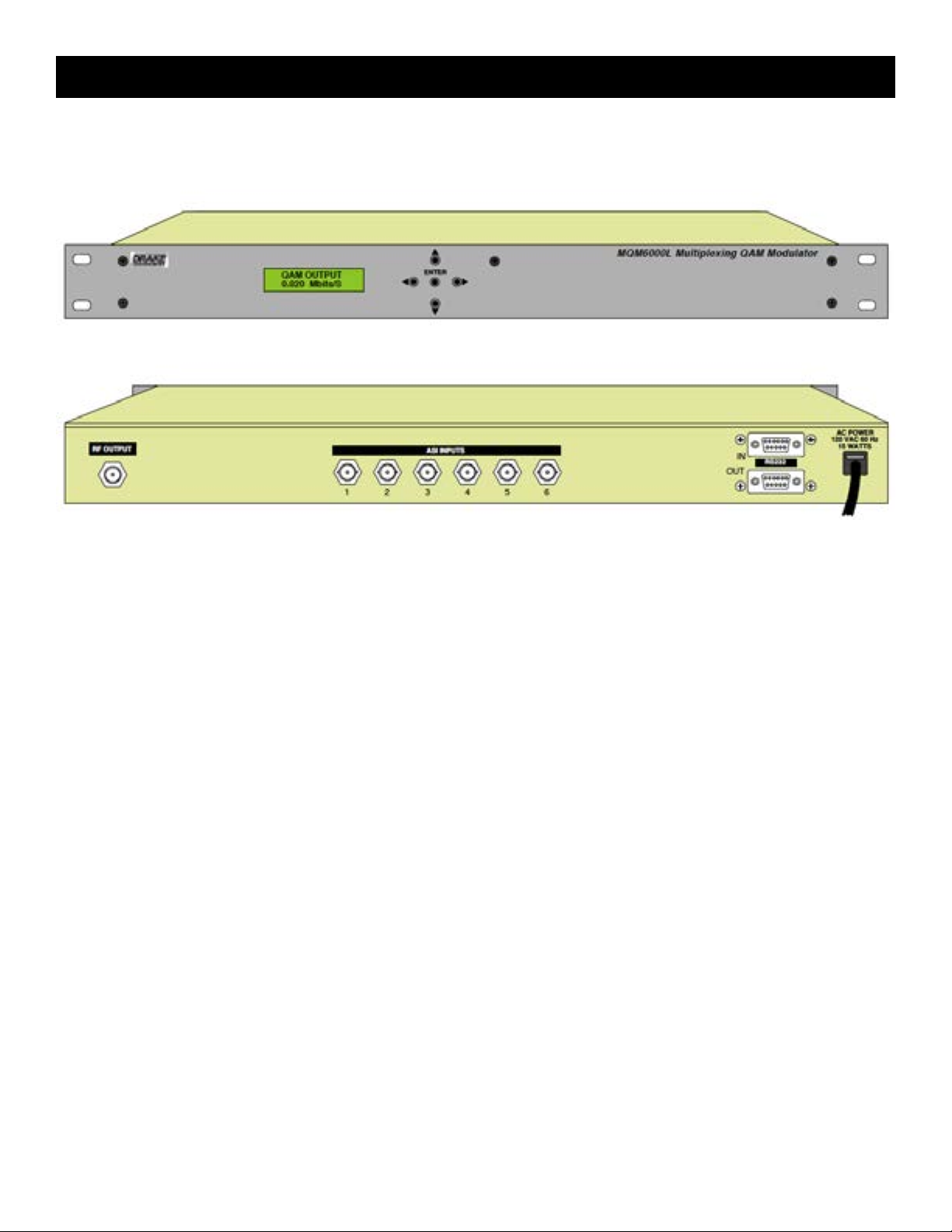
R1, RF OUTPUT – This type "F" connector is the high level (+40 dBmV), 54 to 1002 MHz, output from the
MQM6000L upconverter section.
R2, ASI INPUTS 1 through 6 - These six BNC type connectors each accept multiprogram ASI format MPEG2
transport stream inputs.
7
R3, RS232 IN - Connection to a PC or modem for use with remote control / monitoring program or for firmware
download.
R4, RS232 OUT - Loop to another MQM or DQT.
R5, AC Line Cord – For connection to the nominal 120 VAC power source. This unit is designed for use in countries
with 120 VAC power standards but the power supply will accept an input voltage range of 90 VAC minimum to 260
VAC maximum with a power line frequency of either 50 or 60 Hz. The maximum power consumption is 15 watts.
Page 8
8
Setup and Programming
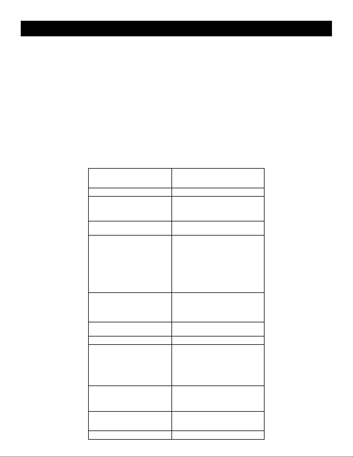
Programming and viewing of the various setup and operating parameters is accomplished using the front panel
back lit, two line, sixteen character wide LCD along with the 4 arrow buttons and the ENTER button. The name
of the parameter is on the top line of the display and the setting value is on the bottom line.
To observe a certain parameter setting without intending to change its value, just use the left and right arrow
buttons to navigate through the menus shown in the list. The current setting for each parameter is shown on the
bottom line of the display. Note that depending upon certain settings, some screens are not needed and will be
skipped.
To make a change in the displayed parameter and its setting and if this is the initial setup, you will want to enter the
‘adjust’ mode. To do this, press the ENTER button that is located in the center of the four arrow buttons and hold in
for several seconds until the display begins to flash. After you are in the adjust mode (bottom line of screen flashing)
use the left and right arrows to navigate among screens and use the up and down arrows to change the parameter
setting. When ENTER is pressed, the new settings will be loaded and stored and the unit will exit the ‘adjust’ mode.
You may wish to not press ENTER until you have gone through all screens and settings and then press ENTER to
save and load all changes in one step OR you can store just one or several parameters at a time and reenter adjust
mode to set the next. Either method is acceptable.
Top display line. Use left/right arrows to
Menu Item
navigate.
UNIT ID: # (0 thru 63)
RS232 BAUDRATE: 2400
MPEG PROGRAMS: DEFAULT
QAM MODE: QAM-16A
GRAY ENCODING: (This menu item only appears if
QAM SYMRATE: PRESET
QAM SYMRATE: x.xxxx MSym/Sec (only in manual)
OUTPUT FORMAT: NORMAL
OUTPUT CHANMAP: BROADCAST
OUTPUT CHANNEL: 2 thru 69 (broadcast)
RF LEVEL: xx.x dBmV (+30 to +42 dBmV)
Parameter Setting Choices
Second display line. Must be in adjust mode to
change using up/down arrows.
4800
9600
19,200
SELECT PROGRAMS
QAM-32A
QAM-64A
QAM-128A
QAM-256A
QAM-512A
QAM-1024A
QAM-64B
QAM-256B
QAM-1024B
QAM modes QAM-16A thru QAM-1024A
are selected.)
DVB
DAVIC
MANUAL
CW
STANDBY
PRBS 15
PRBS 15M
PRBS 24
PRBS 23M
CATV
IRC
HRC
2 thru 158 (CATV)
1 thru 158 (IRC & HRC)
Page 9

Setup and Programming (continued)
UNIT ID: Select the desired unit identification number when connecting the 'RS232 IN' connector to a PC or modem
for remote control using 'Drake Remote Control Software'. Numbers 1 thru 63 may be used. If zero (0) is selected,
the PC will ignore the unit.
RS232 BAUD RATE: This setting determines the baud rate at which the MQM6000L communicates with the remote
PC. Settings available are 2400, 4800, 9600 and 19,200. All units 'daisy chained' to the remote PC or modem must
be set to the same baud rate.
MPEG PROGRAMS: This menu provides selections to determine which programs are multiplexed to form the new
multiprogram transport stream output that will be supplied to the QAM modulator section.
Choose the DEFAULT setting to multiplex the lowest numbered (or only) MPEG program from each of the six ASI
inputs.
Choose the SELECT PROGRAMS setting to allow the operator to pick which program (or no program) from each
of the six ASI inputs is to be included in the output multiplex. Only one program from each of the six inputs can be
selected. This selection must be made using a PC connected to the RS232 IN port and running the 'Drake Digital
Headend Remote Control Software' program.
It is the operator's responsibility to be sure that the total data rate of these programs does not exceed the maximum
data rate for the output QAM mode that will be used. If the total input rate is too large, some programs will have to
be dropped from the multiplex.
9
QAM MODE: This menu allows the user to set the modulation type for the output. Choices range from QAM16A through QAM-1024B. 'A' suffixes indicate DVB compliant FEC and the B suffixes indicate DigiCipher II FEC
encoding. Note that the output QAM mode usually must be QAM-256. For CATV systems using DigiCipher II, select
the QAM-256B mode. For DISH Network QAM distribution or other DVB systems using DVB set tops, choose the
QAM-256A mode.
GRAY ENCODING: This menu is only available when QAM modes QAM-16A through QAM-1024A, are selected.
The choices are DVB and DAVIC. DVB is normally used for video.
QAM SYMRATE: This menu allows selection of the output QAM baudrate or symbol rate. Set as required by the
set top box.
If PRESET is selected, the symbol rate will be set according to the QAM mode that has been selected. If MANUAL
is selected, pressing the right or left arrow buttons will allow selection of symrates from 1.000 thru 7.000 MSym/Sec.
OUTPUT FORMAT: For normal operation, select NORMAL. For system level set up, choose CW to provide a CW
carrier at the center frequency of the output channel for use in leveling a system when a QAM power meter is not
available. In the CW mode, the CW carrier can be measured on a spectrum analyzer without a need to apply a
bandwidth correction or it can be measured with an analog meter tuned to channel center. The CW power measured
will equal the channel QAM power when the modulator is returned to NORMAL output mode. Usually QAM signals
are normally set 5 dB to 10 dB below analog NTSC channels when balancing a system. PRBS menu entries are
used for testing purposes only and should normally not be selected by the user.
OUTPUT CHANMAP, OUTPUT CHANNEL: Select the desired EIA CATV channel output using these two menus.
RF LEVEL: Select the desired RF output signal level. The available range is between +30 dBmV and +42 dBmV,
selectable in 0.5 dB steps. The output accuracy is ± 1 dB.
Page 10

10
Operation
OPERATION
MULTIPLEXING SIX INPUTS
To use the MQM6000L to multiplex six inputs, proceed as follows:
1) Connect the six MPEG2 SPTS or MPTS signal sources to the six ASI input connectors on the rear of the
MQM6000L.
2) Plug the power cord from the unit into the power source.
3) Follow the instructions in the previous programming section to select the desired MPEG programs. (See
the previous section for details.)
4) In the OUTPUT CHANMAP menu, select the output channel format (BROADCAST, CATV, HRC, or IRC).
5) From the OUTPUT CHANNEL menu, select the desired output channel number.
6) From the RF LEVEL menu, select the desired output level. Depending on the diagnostic equipment
available, you may want to select CW from the OUTPUT FORMAT menu to balance the output with the outputs
of the other inputs to the cable system. When finished balancing the system, select NORMAL from this menu.
7) From the QAM MODE menu, set the QAM modulator to QAM-256B for use in a DigiCipher II environment.
If DVB, use QAM-256A instead.
8) In the QAM SYMRATE menu, select PRESET.
9) Set the OUTPUT FORMAT to NORMAL if you have not already done so
Page 11

Additional Information
11
ADDITIONAL INFORMATION
SET TOP BOX MAPPING
The output stream of the MQM6000L will contain programs xx - 1 thru 6 where xx is the RF output channel and
1 thru 6 are the MPEG program numbers assigned that correspond to the ASI inputs1 thru 6.
STANDBY MODE
The MQM6000L has a standby output mode which turns off the RF output. This can be used when it is desirable
to temporarily disable the output without unplugging the AC line cord. Select STANDBY in the OUTPUT FORMAT
menu.
OVER TEMPERATURE SENSOR
Temperature monitoring is built into this product. If inadequate ventilation is provided, overheating may occur.
If this condition is detected, the default LCD message will change to OVER TEMP. If this occurs, the problem
should be corrected as soon as possible. The unit will remain operational but the ventilation must be restored to
prevent premature part failures due to overheating.
STATUS DISPLAYS
When the units are not in the adjust/program mode, status displays are shown. The default display shows the
QAM OUTPUT in Mbits/S. Pressing the down arrow button will show the percentage of buffer capacity that is
currently in use on the left side of the display and the maximum percentage of buffer capacity that has occurred
since the unit was last programmed is displayed on the right side. Pressing the up arrow button will show the
firmware version number.
REMOTE CONTROL AND MONITORING
The MQM6000L may be used with the 'Drake Digital Headend Remote Control Software' program to allow remote
monitoring or control. Make sure that the version of the program includes the MQM6000L. Earlier versions willnot
operate with this unit. Connect the RS232 cable coming from the PC or modem to the RS232 IN DB9 rear panel
connector. Assign a UNIT ID (1 to 63) to use the remote program. Leave at, or set to, 0 if no remote access is
desired. Set the RS232 BAUD RATE to match the PC setting. If you are familiar with the program, operation will
be clear. If not familiar with it, see further instructions in the insert provided with the CDROM or stored on the
CDROM.
Page 12
12
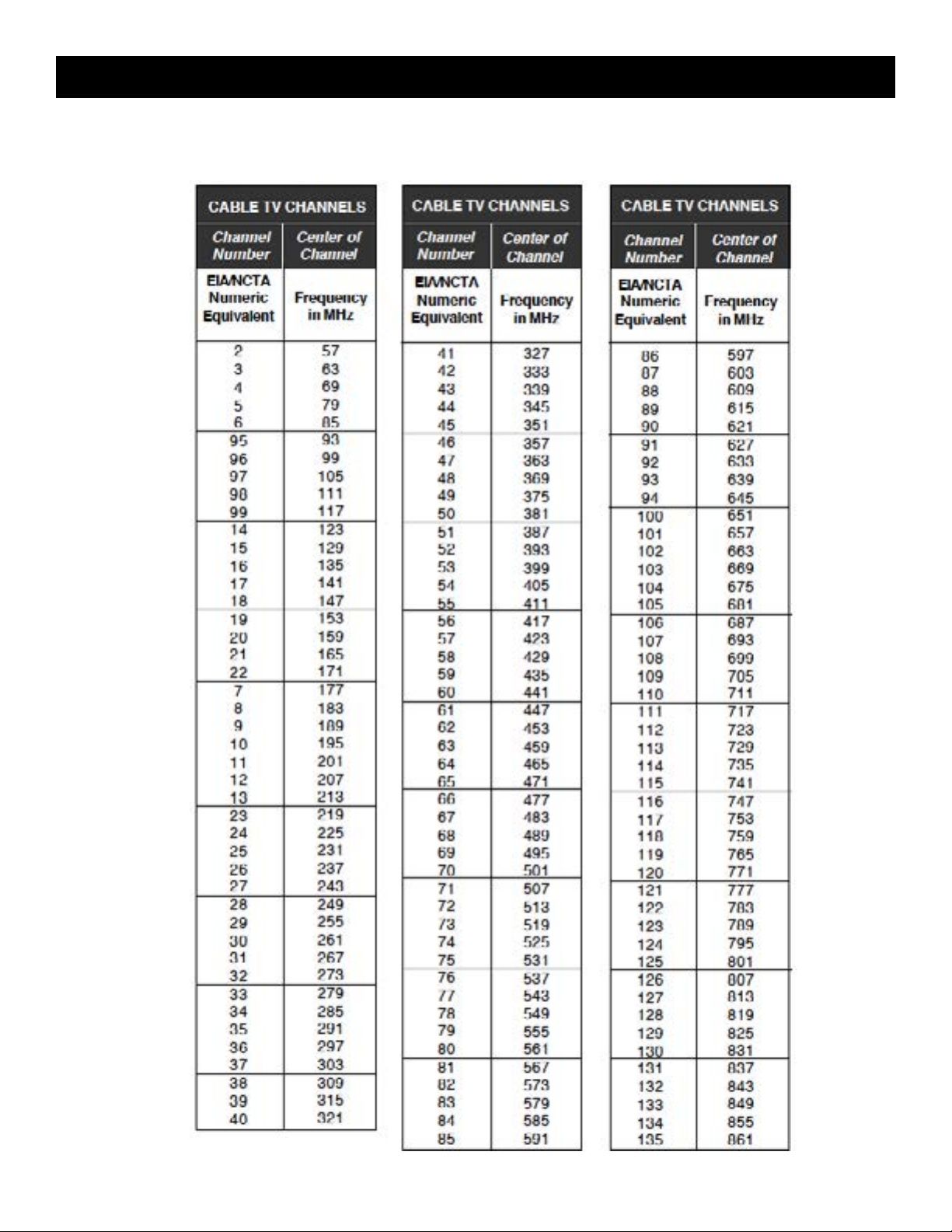
CATV CHANNEL FREQUENCIES
Table 1: CATV
Page 13

Table 2: BC TV
13BROADCAST TV CHANNEL FREQUENCIES
Page 14

14
SERVICE INFORMATION
You may contact the R.L. DRAKE Service Department for additional information or assistance by calling +1 (937)
746-6990, Monday through Friday, between 8:00 A.M. and 4:00 P.M. Eastern Time, except on holidays.
You may also contact the R.L. DRAKE Service Department by E-mail at the following address: TechSupport@
rldrake.com or by Telefax: +1 (937) 806-1510.
Should you want to return your unit for service, package the unit carefully using the original carton or other
suitable container.
Write your return address clearly on the shipping carton and on an enclosed cover letter describing the service
required, symptoms or problems. Also include your daytime telephone number and a copy of your proof of
purchase.
The unit will be serviced under the terms of the R.L. DRAKE HOLDINGS LLC Limited Warranty and returned to
you.
IF YOU NEED TO CALL FOR HELP
Call our Customer Service/Technical Support line at +1 (937) 746-6990 between 8:00 A.M. and 4:00 P.M. Eastern
Time, weekdays. Please have the unit’s serial number available. We will also need to know the specifics of any
other equipment connected to the unit. When calling, please have the unit up and running, near the phone if
possible.
Service / If You Need To Call For Help
Our technician(s) will likely ask certain questions to aid in diagnosis of the problem. Also, have a voltmeter handy,
if possible. R.L. DRAKE also provides technical assistance by e-mail: TechSupport@rldrake.com or by Telefax: +1
(937) 806-1510.
Many of the products that are sent to us for repair are in perfect working order when we receive them. For these
units, there is a standard checkout fee that you will be charged. Please perform whatever steps are applicable
from the installation sections of the Owner's Manual before calling or writing—this could save unnecessary phone
charges. Please do not return the unit without contacting R.L. DRAKE first: it is preferred to help troubleshoot the
problem over the phone (or by mail) first, saving you both time and money.
Inside the carton, enclose a note with your name, address, daytime phone number, and a description of the unit’s
problem.
The unit must be sent to the following address:
Service Department
R.L. DRAKE
710 Pleasant Valley Drive
Springboro, Ohio 45066. USA
Be sure to include your street address which will be needed for UPS return. UPS Surface (Brown Label) takes
7-10 days to reach us depending on your location, Blue takes 2-3 days.
Red is an overnight service. Send the unit in a way that it can be traced if we can’t verify receipt of shipment. We
suggest UPS or insured postal shipment.
If the unit is still under the original owner’s warranty, R.L. DRAKE will pay the cost of the return shipment to you.
Our return shipping policy is that we will return it UPS Brown if received Brown or by US Mail, it will be returned
Blue if received Blue or Red—or it will be returned however you prefer if you furnish the return cost for the
method you select.
Page 15

If You Need To Call For Help (continued)
If the unit is out of warranty, use one of the following methods for return shipment:
1) You designate billing to American Express, VISA, MasterCard or Discover card;
2) You prepay the service charges with a personal check, or
3) You specify some other method of return and payment.
When calling, the technician can estimate the repair charges for you over the phone. This is another good reason
to call before sending a unit in for repair.
Typically, equipment is repaired in five to ten working days after it arrives at R.L. DRAKE if we have all the
facts. If we must call you, it may take longer. R.L. DRAKE is not responsible for damage caused by lightning,
nonprofessional alterations, “acts of God”, shipping damage, poor storage/handling, etc. R.L. DRAKE will make
note of any shipping damage upon receipt.
You will need to send proof of purchase to receive warranty service. Typically, a copy of the invoice from an R.L.
DRAKE dealer will suffice. The warranty is for the original owner only and is not transferable.
15
Page 16

16
Warranty
Three Year Limited Warranty
R.L. DRAKE HOLDINGS LLC warrants to the original purchaser this product shall be free from defects in material
or workmanship for three (3) years from the date of original purchase.
During the warranty period R.L. DRAKE HOLDINGS LLC or an authorized Drake service facility will provide,
free of charge, both parts and labor necessary to correct defects in material and workmanship. At its option, R.L.
DRAKE HOLDINGS LLC may replace a defective unit.
To obtain such a warranty service, the original purchaser must:
1. Retain invoice or original proof of purchase to establish the start of the warranty period.
Notify R.L. DRAKE HOLDINGS LLC or the nearest authorized service facility, as soon as possible after
2.
discovery of a possible defect, of:
a) the model and serial number,
b) the identity of the seller and the approximate date of purchase; and
A detailed description of the problem, including details on the electrical connection to associated
c)
equipment and the list of such equipment.
Deliver the product to R.L. DRAKE HOLDINGS LLC or the nearest authorized service facility, or ship
3.
the same in its original container or equivalent, fully insured and shipping charges prepaid.
Correct maintenance, repair, and use are important to obtain proper performance from this product. Therefore
carefully read the Instruction Manual. This warranty does not apply to any defect that R.L. DRAKE HOLDINGS
LLC determines is due to:
Improper maintenance or repair, including the installation of parts or accessories that do not conform
1.
to the quality and specifications of the original parts.
2. Misuse, abuse, neglect or improper installation.
3. Accidental or intentional damage.
All implied warranties, if any, including warranties of merchantability and fitness for a particular purpose, terminate
three (3) years from the date of the original purchase.
The foregoing constitutes R.L. DRAKE HOLDINGS LLC'S entire obligation with respect to this product, and the
original purchaser shall have no other remedy and no claim for incidental or consequential damages, losses or
expenses. Some states do not allow limitations on how long an implied warranty lasts or do not allow the exclusions
or limitation of incidental or consequential damages, so the above limitation and exclusion may not apply to you.
This warranty gives you specific legal rights and you may also have other rights which vary from state to state.
This warranty shall be construed under the laws of Ohio.
For Service, contact:
R.L. DRAKE HOLDINGS LLC
710 Pleasant Valley Drive
Springboro, Ohio 45066 USA
Customer Service and Parts Telephone: +1 (937) 746-6990
Telefax: +1 (937) 806-1510
Web Site: http://www.rldrake.com
Page 17

[THIS PAGE IS INTENTIONALLY LEFT BLANK]
Page 18

[THIS PAGE IS INTENTIONALLY LEFT BLANK]
Page 19

[THIS PAGE IS INTENTIONALLY LEFT BLANK]
Page 20

R.L. Drake Holdings, LLC
710 Pleasant Valley Drive
Springboro, OH 45066
(937) 746-4556
www.rldrake.com
 Loading...