

DRAKE MEQ1000B Instruction Manual
MEQ1000B Hybrid QAM Modulator
Multi-solution Edge QAM Platform
INSTRUCTION MANUAL
Model Item # Description
MEQ1000B 1002511B Multiplexing QAM Modulator w/ dual input bays
Program Acquisition Modules
DTD1000A 1002512A Digital Tuner and Demodulator Module - 8VSB/QAM
SDM1000 1002576 Satellite Tuner and Demodulator Module - QPSK/8PSK
IPI1000 1002608 IP Input Module – GigE
ASII 1002397 ASI Input Module w/ loop thru
MPEG Encoder Modules
SDE24A 1002514A SD Dual Video Encoder Module
HDE24A 1002515A HD Video Encoder Module
SDI24A 1002516A SDI Video Encoder Module
© 2015 R.L. Drake Holdings, LLC.
Rev: 120415 / 651238000A

We recommend that you write the following information in the spaces provided below.
Purchase Location Name:
Purchase Location Telephone Number:
MEQ1000B Serial Number:
This product incorporates copyright protection technology that is protected by U.S. patents and other
intellectual property rights. Reverse engineering or disassembly is prohibited.
Manual Revision
This is the first release of the instruction manual for MEQ1000B using a firmware release version of 1.0.
For more information regarding product firmware releases, please visit our website at www.rldrake.com
You may also contact Technical Assistance at 937-746-6990 or by email: servicehelp@rldrake.com.
2

Table of Contents
CAUTION STATEMENTS ......................................................................................................................................................... 4
IMPORTANT SAFETY INSTRUCTIONS
SPECIFICATIONS
INSTALLATION & POWER-UP
GENERAL DESCRIPTION & FEATURES
FRONT AND REAR PANEL OPERATION
LOGIN SCREEN
STATUS TAB
MODULES TAB
MODULE: IPI1000 IP INPUT MODULE
MODULE: DTD1000A DEMODULATOR MODULE
MODULE: SDI24A ENCODER MODULE
MODULE: ASII ASI INPUT MODULE
MODULE: SDE24A ENCODER MODULE
MODULE: HDE24A ENCODER MODULE
MODULE: SDM1000 SATELLITE DEMODULATOR MODULE
MULTIPLEX TAB
CHANNELS TAB
OUTPUT TAB
EAS/DTA TAB
SYSTEM CONFIGURATION TAB
LOG TAB
ADMIN SCREEN
FIRMWARE UPDATE TAB
SERVICE
WARRANTY
................................................................................................................................................................................. 31
.................................................................................................................................................................................. 34
.................................................................................................................................................................... 6
................................................................................................................................................ 8
...................................................................................................................................................................... 12
........................................................................................................................................................................... 13
....................................................................................................................................................................... 14
..................................................................................................................................................................... 24
..................................................................................................................................................................... 26
.......................................................................................................................................................................... 27
.......................................................................................................................................................................... 28
..................................................................................................................................................................... 32
...................................................................................................................................................... 33
............................................................................................................................................................................. 35
................................................................................................................................. 4
............................................................................................................................... 9
............................................................................................................................. 10
............................................................................................................................. 14
........................................................................................................... 15
.......................................................................................................................... 16
................................................................................................................................ 17
......................................................................................................................... 18
......................................................................................................................... 20
........................................................................................ 22
........................................................................................................................................... 30
3
Caution Statements
DSE 2 PLUS | 2
Instruction Manual
Rev: 20140
Table of Contents
IMPORTANT SAFETY INSTRUCTIONS...................................................................................................................................................... 2
SPECIFICATIONS............................................................................................................................................................................................ 4
GENERAL DESCRIPTION.............................................................................................................................................................................. 6
FEATURES........................................................................................................................................................................................................ 6
INSTALLATION AND MOUNTING .............................................................................................................................................................. 6
REAR PANEL CONNECTIONS ..................................................................................................................................................................... 7
ETHERNET ACCESS ....................................................................................................................................................................................... 8
SETUP AND PROGRAMMING ................................................................................................................................................................... 10
FIRMWARE UPDATE.................................................................................................................................................................................... 15
SERVICE / IF YOU NEED TO CALL FOR HELP ........................................................................................................................................ 18
WARRANTY .............................................................................................................................................................................................................. 19
DSE 2 PLUS | 3
Instruction Manual
product. Any mounting of the product should follow the manufacturer's instructions, and should use a mounting accessory recommended by the
manufacturer.
9.
A product and cart combination should be moved with care. Quick stops, excessive force, and uneven surfaces may cause the product and cart combination
to overturn.
10.
Ventilation: Slots and openings in the cabinet are provided for ventilation and to ensure reliable operation of the product and to protect it from overheating,
and these openings must not be blocked or covered. The openings should never be blocked by placing the product on a bed, sofa, rug, or similar
surface. This product should not be placed in a built-in installation such as bookcase or rack unless proper ventilation is provided or the manufacturer's
instructions have been adhered to.
11.
Power Sources: This product should be operated only from the type of power source indicated on the marking label. If you are not sure of the type of power
supplied to your home, consult your product dealer or local power compan y. For products intended to operate from battery power, or other sources, refer to the
product's operating instructions.
12.
Grounding or Polarization: This product may be equipped with a polarized alternating-current line plug (a plug having one blade wider than the
other). This plug will fit into the power outlet only one way. This is a safety feature. If you are unable to inser
t the plug fully into the outlet, tr y reversing
the plug. If the plug should still fail to fit, contact your electrician to replace your obsolete outlet. Do not defeat the safety purpose of the polarized
plug. Alternate Warnings – If this product is equipped with a three-wire grounding- type plug, a plug having a third (grounding) pin, the plug will only fit
into a grounding-type power outlet. This is a safety feature. If you are unable to insert the plug into the outlet, contact your electrician to replace your
obsolete outlet. Do not defeat the safety purpose of the grounding-type plug.
DSE 2 PLUS | 2
Instruction Manual
Rev: 20140
Table of Contents
IMPORTANT SAFETY INSTRUCTIONS...................................................................................................................................................... 2
SPECIFICATIONS............................................................................................................................................................................................ 4
GENERAL DESCRIPTION.............................................................................................................................................................................. 6
FEATURES........................................................................................................................................................................................................ 6
INSTALLATION AND MOUNTING .............................................................................................................................................................. 6
REAR PANEL CONNECTIONS ..................................................................................................................................................................... 7
ETHERNET ACCESS ....................................................................................................................................................................................... 8
SETUP AND PROGRAMMING ................................................................................................................................................................... 10
FIRMWARE UPDATE.................................................................................................................................................................................... 15
SERVICE / IF YOU NEED TO CALL FOR HELP ........................................................................................................................................ 18
WARRANTY .............................................................................................................................................................................................................. 19
Caution Statements:
WARNING:
TO PREVENT FIRE OR ELECTRICAL
SHOCK, DO NOT EXPOSE TO RAIN OR MOISTURE.
A product and cart combination should be moved
with care.
Quick stops, excessive force and uneven surfaces may
cause the product and cart combination to overturn.
The lightning flash with arrow head symbol, within an
equilateral
triangle, i
s intended to alert the user to
the presence of uninsulated "dangerous voltage"
within the product's enclosure
that may be of
sufficient magnitude to constitute a risk of electric
shock to
persons.
The exclamation point within an equilateral triangle
is intended to alert the user to the presence of
important operating and maintenance (servicing)
instructions in the literature
acco
mpanying the
product.
WARNING: THE SOCKET-OUTLET SHALL BE INSTALLED NEAR THE EQUIPMENT AND SHALL BE EASILY ACCESSIBLE.
WARNING: TO REDUCE THE RISK OF FIRE OR ELEC
TRIC SHOCK, DO NOT EXPOSE THIS PRODUCT TO RAIN OR
MOISTURE. DO NOT OPEN THE CABINE T, REFER SERVICING TO QUALIFIED PERSONNEL ONLY.
CAUTION: TO PREVENT ELECTRIC SHOCK, DO NOT USE THIS (POLARIZED) PLUG WITH AN EXTENSION CORD
RECEPTACLE OR OTHER OUTLET UNLESS THE BLADES CAN BE FULLY INSERTED TO PREVENT BLADE
EXPOSURE.
ATTENTION: POUR PREVENIR LES CHOCS ELECTRIQUES , N E PAS UTILISER CETTE FICHE POLARISEE AVEC UN
PROLONGATEUR, UNE PRISE DE COURANT OU UNE AUTRE SORTIE DE COURANT, SAUF SI LES LAMES
PEUVENT ETRE INSEREES A FOND SANS E N LAISSER AUCUNE PA R TIE A DECOUVER T.
Important Safety Instructions:
1.
Read Instructions: All the safety and operating instructions should be read before the product is operated.
2.
Retain Instructions: The safety and operating instructions should be retained for future reference.
3.
Heed Warnings: All warnings on the product and in the operating instructions should be adhered to.
4.
Follow Instructions: All operating and use instructions should be followed.
5.
Cleaning: Unplug this product from the wall outlet before cleaning. Do not use liquid cleaners or aerosol cleansers. Use a damp cloth for cleaning.
6.
Attachments: Do not use attachments that are not re commended by the product manufacturer as they may cause hazards.
7.
Water and Moisture: Do not use this product near water—for example, near a bathtub, wash bowl, kitchen sink or laundry tub; in a wet basement;
or near a swimming pool; and the like.
8.
Accessories: Do not place this product on an unstable cart, stand, tripod, bracket, or table. The product may fall, causing serious injury to a child or
adult, and serious damage to the product. Use only with a cart, stand, tripod, bracket, or table recommended by the manufacturer, or sold with the
Caution Statements:
A product and cart combination should be moved
WARNING:
SHOCK, DO NOT EXPOSE TO RAIN
TO PREVENT FIRE OR ELECTRICAL
OR MOISTURE.
with care.
Quick stops, excessive force and uneven surfaces may
cause the product and cart combination to overturn.
The lightning flash with arrow head symbol, within an
equilateral
the presence of uninsulated "dangerous voltage"
within the product's enclosure
sufficient magnitude to constitute a risk of electric
shock to persons.
The exclamation point within an equilateral triangle
is intended to alert the user to the presence of
important operating and maintenance (servicing)
instructions in the literature
product.
triangle, is intended to alert the user to
accompanying the
that may be of
WARNING: THE SOCKET-OUTLET SHALL BE INSTALLED NEAR THE EQUIPMENT AND SHALL BE EASILY ACCESSIBLE.
WARNING: TO REDUCE THE RISK O F FIRE OR ELECTRIC SHOCK, DO NOT EXPOSE THIS PRODUCT TO RAIN OR
MOISTURE. DO NOT OPEN THE CABINE T, REFER SERVICING TO QUALIFIED PERSONNEL ONLY.
CAUTION: TO PREVENT ELECTRIC SHOCK, DO NOT USE THIS (POLARIZED) PLUG WITH AN EXTENSION CORD
RECEPTACLE OR OTHER OUTLET UNLESS THE BLADES CAN BE FULLY INSERTED TO PREVENT BLADE
EXPOSURE.
ATTENTION: POUR PREVENIR LES CHOCS ELECTRIQUES , NE PA S UTILISER CETTE FICHE POLARISEE AVEC UN
PROLONGATEUR, UNE PRISE DE CO
URANT OU UNE AUTRE SORTIE DE COURANT, SAUF SI LES LAMES
PEUVENT ETRE INSEREES A FOND SANS EN LAISSER AUCUNE PAR TIE A DECOUVERT.
Important Safety Instructions
4
Safety Instructions continued...
DSE 2 PLUS | 3
Instruction Manual
product. Any mounting of the product should follow the manufacturer's instructions, and should use a mounting accessory recommended by the
manufacturer.
A product and cart combination should be moved with care. Quick stops, excessive force, and uneven surfaces may cause the product and cart combination
to overturn.
Ventilation: Slots and openings in the cabinet are provided for ventilation and to ensure reliable operation of the product and to protect it from overheating,
and these openings must not be blocked or covered. The openings should never be blocked by placing the product on a bed, sofa, rug, or similar
surface. This product should not be placed in a built-in installation such as bookcase or rack unless proper ventilation is provided or the manufacturer's
instructions have been adhered to.
Power Sources: This product should be operated only from the type of power source indicated on the marking label. If you are not sure of the type of power
supplied to your home, consult your product dealer or local power compan y. For products intended to operate from battery power, or other sources, refer to the
product's operating instructions.
Grounding or Polarization: This product may be equipped with a polarized alternating-current line plug (a plug having one blade wider than the
other). This plug will fit into the power outlet only one way. This is a safety feature. If you are unable to inser
t the plug fully into the outlet, tr y reversing
the plug. If the plug should still fail to fit, contact your electrician to replace your obsolete outlet. Do not defeat the safety purpose of the polarized
plug. Alternate Warnings – If this product is equipped with a three-wire grounding- type plug, a plug having a third (grounding) pin, the plug will only fit
into a grounding-type power outlet. This is a safety feature. If you are unable to insert the plug into the outlet, contact your electrician to replace your
obsolete outlet. Do not defeat the safety purpose of the grounding-type plug.
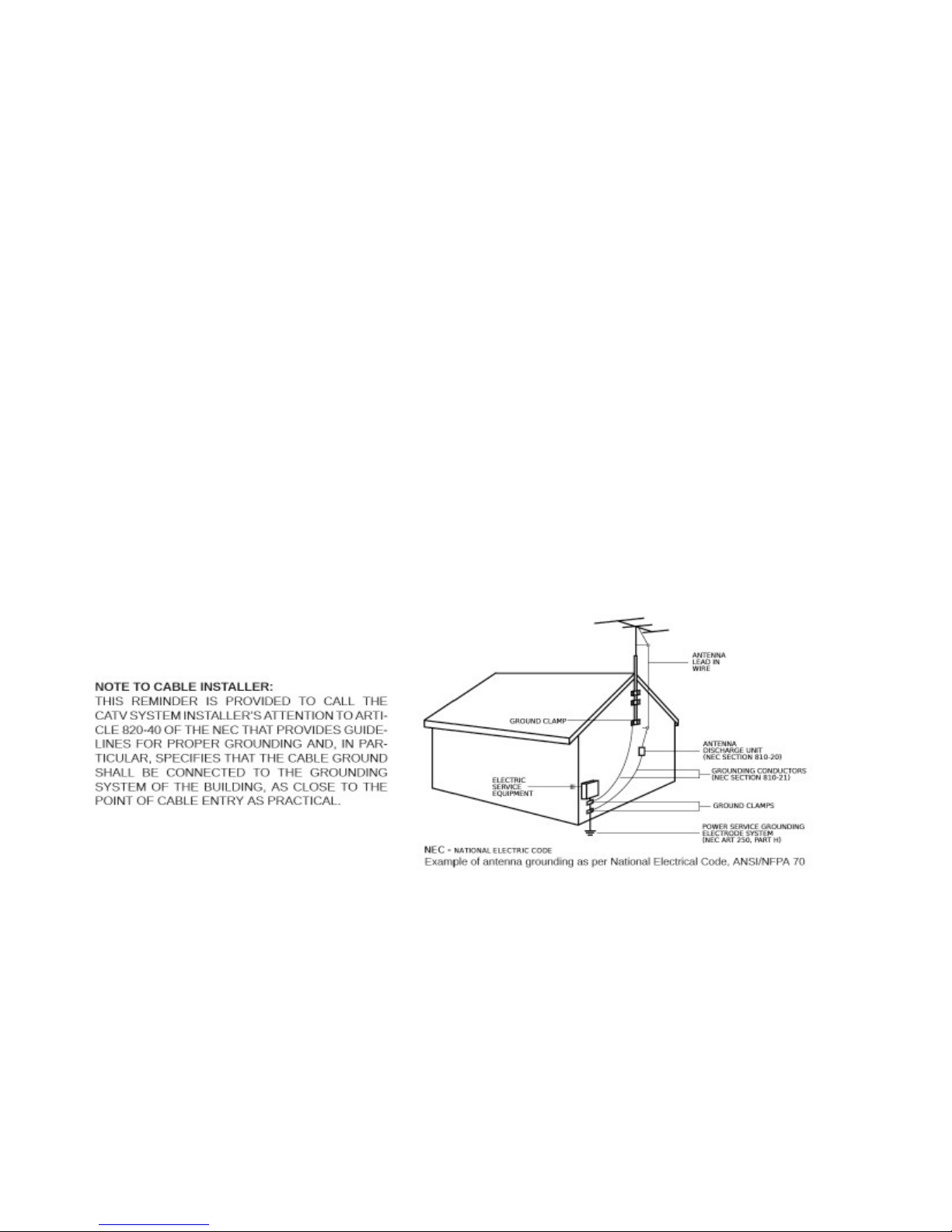
Outdoor Antenna Grounding: If an outside antenna or cable system is connected to the product, be sure the antenna or cable system is
grounded so as to provide some protection against voltage surges and built-up static charges. Article 810 of the National Electrical Code,
ANSI/NFPA 70, provides information with regard to proper grounding of the mast and supporting structure, grounding of the lead-in wire
to an antenna discharge unit, size of grounding conductors, location of antenna-discharge unit, connection to grounding electrodes, and
requirements for the grounding electrode.
Power-Cord Protection: Power-supply cords should be routed so that they are not likely to be walked on or pinched by items placed upon or against them,
paying particular attention to cords at plugs, convenience receptacles, and the point w
here they exit from the product.
Lightning: For added protection for this product during a lightning storm, or when it is left unattended and unused for long periods of time, unplug it
from the wall outlet and disconnect the antenna or cable system. This will prevent damage to the product due to lightning and power-line surges.
Power Lines: An outside antenna system should not be located in the vicinity of overhead power lines, other electric light or power circuits, where it
can fall into such power lines or circuits. When installing an outside antenna system, extreme care should be taken to keep from touching such power
lines or circuits as contact with them may be fatal.
Overloading: Do not overload wall outlets, extension cords, or integral convenience receptacles as this can result in a risk of fire or electric shock.
Object and Liquid Entry: Never push objects of any kind into this product through openings as they may touch dangerous voltage points or short-out
parts that could result in a fire or electric shock. Never spill liquid of any kind on the product.
Servicing: Do not attempt to service this product yourself as opening or removing covers may expose you to dangerous voltage or other hazards.
Refer all servicing
to qualified service personnel.
Damage Requiring Service: Unplug this product from the wall outlet and refer servicing to qualified service personnel under the following conditions:
a) When the power-supply cord or plug is damaged,
b) If liquid has been spilled, or objects have fallen into the product,
c) If the product has been exposed to rain or wate r,
d) If the product does not operate normally by following the operating instructions.
Adjust only those controls that are cove red by the operating instructions as an improper adjustment of other controls may result in damage and will
often require extensive work by a qualified technician to restore the product to its normal operation, e. If the product has been dropped or damaged
in any way, and f. When the product exhibits a distinct change in performance—this indicates a need for service.
Replacement Parts: When replacement parts are required, be sure the service technician has used replacement parts specified by the manufacturer
or have the same characteristics as the original part. Unauthorized substitutes may result in fire, electric shock or other hazards.
Safety Check: Upon completion of any service or repairs to this product, ask the service technician to perform safety checks to determine that the
product is in proper operating condition.
Wall or Ceiling Mounting: The product should be mounted to a wall or ceiling only as recommended by the manufacturer.
5
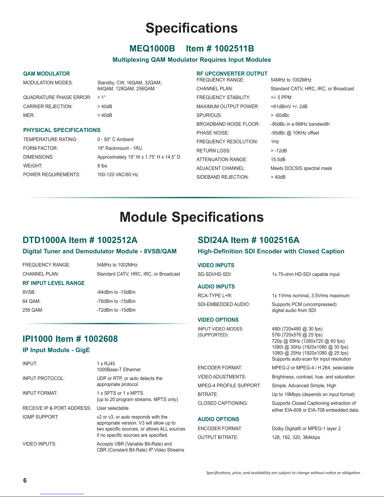
Specifications
MEQ1000B Item # 1002511B
Multiplexing QAM Modulator Requires Input Modules
QAM MODULATOR
MODULATION MODES: Standby, CW, 16QAM, 32QAM,
64QAM, 128QAM, 256QAM
QUADRATURE PHASE ERROR: < 1°
CARRIER REJECTION: > 40dB
MER: > 40dB
PHYSICAL SPECIFICATIONS
TEMPERATURE RATING: 0 - 50° C Ambient
FORM FACTOR: 19" Rackmount - 1RU
DIMENSIONS: Approximately 19” W x 1.75” H x 14.5” D
WEIGHT: 8 lbs
POWER REQUIREMENTS: 100-120 VAC/60 Hz
Module Specifications
DTD1000A Item # 1002512A
Digital Tuner and Demodulator Module - 8VSB/QAM
RF UPCONVERTER OUTPUT
FREQUENCY RANGE: 54MHz to 1002MHz
CHANNEL PLAN: Standard CATV, HRC, IRC, or Broadcast
FREQUENCY STABILITY: +/- 5 PPM
MAXIMUM OUTPUT POWER: +61dBmV +/- 2dB
SPURIOUS: > -60dBc
BROADBAND NOISE FLOOR: -80dBc in a 6MHz bandwidth
PHASE NOISE: -95dBc @ 10KHz offset
FREQUENCY RESOLUTION: 1Hz
RETURN LOSS: > -12dB
ATTENUATION RANGE: 15.5dB
ADJACENT CHANNEL: Meets DOCSIS spectral mask
SIDEBAND REJECTION: > 40dB
SDI24A Item # 1002516A
High-Definition SDI Encoder with Closed Caption
FREQUENCY RANGE: 54MHz to 1002MHz
CHANNEL PLAN: Standard CATV, HRC, IRC, or Broadcast
RF INPUT LEVEL RANGE
8VSB: -84dBm to -15dBm
64 QAM: -78dBm to -15dBm
256 QAM:
-72dBm to -15dBm
IPI1000 Item # 1002608
IP Input Module - GigE
INPUT: 1 x RJ45
INPUT PROTOCOL: UDP or RTP, or auto detects the
INPUT FORMAT: 1 x SPTS or 1 x MPTS
RECEIVE IP & PORT ADDRESS: User selectable
IGMP SUPPORT: v2 or v3, or auto responds with the
VIDEO INPUTS: Accepts VBR (Variable Bit-Rate) and
1000Base-T Ethernet
appropriate protocol.
(up to 20 program streams, MPTS only)
appropriate version. V3 will allow up to
twospecicsources,orallowsALLsources
ifnospecicsourcesarespecied.
CBR (Constant Bit-Rate) IP Video Streams
VIDEO INPUTS
SD-SDI/HD-SDI: 1x 75-ohm HD-SDI capable input
AUDIO INPUTS
RCA-TYPE L+R: 1x 1Vrms nominal, 3.5Vrms maximum
SDI-EMBEDDED AUDIO: Supports PCM (uncompressed)
digital audio from SDI
VIDEO OPTIONS
INPUT VIDEO MODES: 480i (720x480 @ 30 fps)
(SUPPORTED) 576i (720x576 @ 25 fps)
720p @ 69Hz (1280x720 @ 60 fps)
1080i @ 30Hz (1920x1080 @ 30 fps)
1080i @ 25Hz (1920x1080 @ 25 fps)
Supports auto-scan for input resolution
ENCODER FORMAT: MPEG-2 or MPEG-4 / H.264, selectable
VIDEO ADUSTMENTS: Brightness, contrast, hue, and saturation
MPEG-4 PROFILE SUPPORT: Simple, Advanced Simple, High
BITRATE: Up to 19Mbps (depends on input format)
CLOSED CAPTIONING: Supports Closed Captioning extraction of
either EIA-608 or EIA-708 embedded data.
AUDIO OPTIONS
ENCODER FORMAT: Dolby Digital® or MPEG-1 layer 2
OUTPUT BITRATE: 128, 192, 320, 384kbps
6
Specicaons, price, and availability are subject to change without noce or obligaon.
Module Specifications
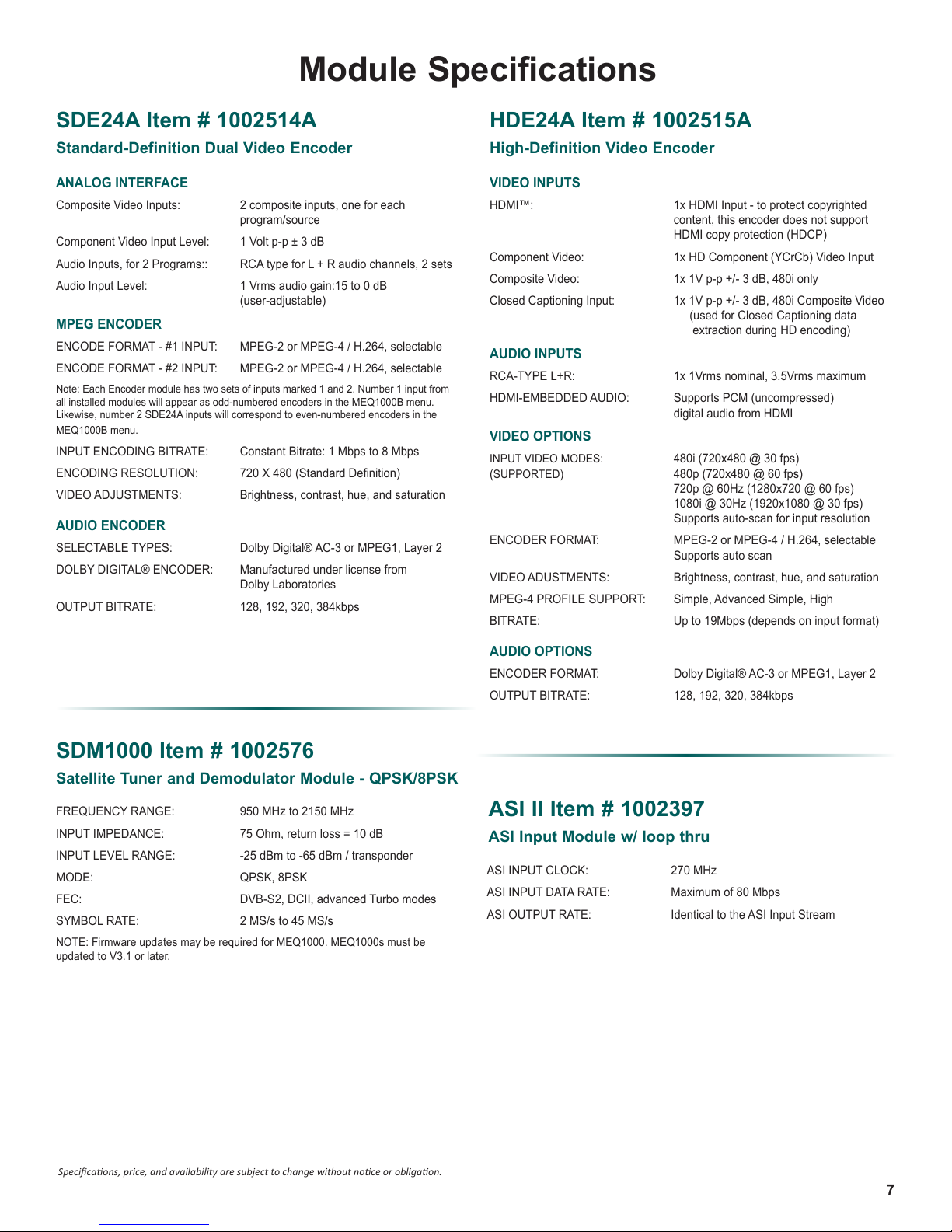
SDE24A Item # 1002514A
Standard-Definition Dual Video Encoder
ANALOG INTERFACE
Composite Video Inputs: 2 composite inputs, one for each
program/source
Component Video Input Level: 1 Volt p-p ± 3 dB
Audio Inputs, for 2 Programs:: RCA type for L + R audio channels, 2 sets
Audio Input Level: 1 Vrms audio gain:15 to 0 dB
(user-adjustable)
MPEG ENCODER
ENCODE FORMAT - #1 INPUT: MPEG-2 or MPEG-4 / H.264, selectable
ENCODE FORMAT - #2 INPUT: MPEG-2 or MPEG-4 / H.264, selectable
Note: Each Encoder module has two sets of inputs marked 1 and 2. Number 1 input from
all installed modules will appear as odd-numbered encoders in the MEQ1000B menu.
Likewise, number 2 SDE24A inputs will correspond to even-numbered encoders in the
MEQ1000B menu.
INPUT ENCODING BITRATE: Constant Bitrate: 1 Mbps to 8 Mbps
ENCODING RESOLUTION: 720X480(StandardDenition)
VIDEO ADJUSTMENTS: Brightness, contrast, hue, and saturation
AUDIO ENCODER
SELECTABLE TYPES: Dolby Digital® AC-3 or MPEG1, Layer 2
DOLBY DIGITAL® ENCODER: Manufactured under license from
Dolby Laboratories
OUTPUT BITRATE: 128, 192, 320, 384kbps
HDE24A Item # 1002515A
High-Definition Video Encoder
VIDEO INPUTS
HDMI™: 1x HDMI Input - to protect copyrighted
content, this encoder does not support
HDMI copy protection (HDCP)
Component Video: 1x HD Component (YCrCb) Video Input
Composite Video: 1x 1V p-p +/- 3 dB, 480i only
Closed Captioning Input: 1x 1V p-p +/- 3 dB, 480i Composite Video
(used for Closed Captioning data
extraction during HD encoding)
AUDIO INPUTS
RCA-TYPE L+R: 1x 1Vrms nominal, 3.5Vrms maximum
HDMI-EMBEDDED AUDIO: Supports PCM (uncompressed)
digital audio from HDMI
VIDEO OPTIONS
INPUT VIDEO MODES: 480i (720x480 @ 30 fps)
(SUPPORTED) 480p (720x480 @ 60 fps)
720p @ 60Hz (1280x720 @ 60 fps)
1080i @ 30Hz (1920x1080 @ 30 fps)
Supports auto-scan for input resolution
ENCODER FORMAT: MPEG-2 or MPEG-4 / H.264, selectable
Supports auto scan
VIDEO ADUSTMENTS: Brightness, contrast, hue, and saturation
MPEG-4 PROFILE SUPPORT: Simple, Advanced Simple, High
BITRATE: Up to 19Mbps (depends on input format)
SDM1000 Item # 1002576
Satellite Tuner and Demodulator Module - QPSK/8PSK
FREQUENCY RANGE: 950 MHz to 2150 MHz
INPUT IMPEDANCE: 75 Ohm, return loss = 10 dB
INPUT LEVEL RANGE: -25 dBm to -65 dBm / transponder
MODE: QPSK, 8PSK
FEC: DVB-S2, DCII, advanced Turbo modes
SYMBOL RATE: 2 MS/s to 45 MS/s
NOTE: Firmware updates may be required for MEQ1000. MEQ1000s must be
updated to V3.1 or later.
AUDIO OPTIONS
ENCODER FORMAT: Dolby Digital® AC-3 or MPEG1, Layer 2
OUTPUT BITRATE: 128, 192, 320, 384kbps
ASI II Item # 1002397
ASI Input Module w/ loop thru
ASI INPUT CLOCK: 270 MHz
ASI INPUT DATA RATE: Maximum of 80 Mbps
ASI OUTPUT RATE: Identical to the ASI Input Stream
Specicaons, price, and availability are subject to change without noce or obligaon.
7

Installation & Power-Up
DSE 2 PLUS | 2
Instruction Manual
Rev: 20140
A product and cart combination should be moved
with care.
Quick stops, excessive force and uneven surfaces may
cause the product and cart combination to overturn.
The lightning flash with ar rowhead symbol, within an
equilateral
triangle, i
s intended to alert the user to
the presence of uninsulated "dangerous voltage"
within the product's enclosure
that may be of
sufficient magnitude to constitute a risk of electric
shock to
persons.
The exclamation point within an equilateral triangle
is intended to alert the user to the presence of
important operating and maintenance (servicing)
instructions in the literature
acco
mpanying the
Unpacking
You will find the following items in the box:
• MEQ1000B Multiplexing QAM Modulator Unit (QTY = 1)
• MEQ1000B Instruction Manual
Installation
The MEQ1000B is designed to be mounted in the close proximity to a 120 VAC – 60 HZ power plug.
For safe and reliable operation, do not block airflow.
Power-Up
Plug into the power plug (120 VAC – 60 HZ).
8

General Description & Features
The R.L. Drake model MEQ1000B is a commercial grade hybrid QAM modulator. The MEQ1000B features plug-in
input modules that include an ATSC/QAM tuner, Satellite L-band tuner, GigE IP input, an ASI input, a SDI/HD-SDI input,
HDMI (non-HDCP), Composite input, Component input, and analog NTSC inputs; thus the description 'hybrid' is used
to describe it. A multiplexer is built in to combine the transport streams and input the filtered and groomed transport
stream to the QAM modulator. This manual includes feature examples utilizing the Drake DTD1000A Digital Tuner and
Demodulator Module, IPI1000 GigE IP module, SDM1000 Satellite Tuner and the ASII ASI-Input Module. Other available
input modules include: SDE24A Dual SD MPEG Encoder, HDE24A High Definiton MPEG Encoder and SDI24A SDI/
HD-SDI Input Encoder. In addition, the MEQ1000B also supports older versions of these modules.
The MEQ1000B has two input module slots and the outputs interface to the MEQ1000B multiplexer, internally where
they are MPEG program filtered, multiplexed, and groomed. Programs among the total group from input Slot 1 and input
Slot 2 may be selected or not selected by the operator to be sent to the QAM modulator. Each input must contain no
more than 20 programs and a maximum of 20 programs per input may be selected. Also, the total bitrate of the selected
programs must not exceed that of the output QAM channel capacity.
Some common applications include: Channel Drop/Add, cherry picking programs from ASI or IP inputs, digital channel
processing, or local origination additions.
The MEQ1000B contains a high performance QAM modulator that can operate in most ITU-A or ITU-B modes up
through 256QAM. The very low noise, high output, up- converter provides coverage from 54 MHz to 1002 MHz while
maintaining exceptionally low phase noise and broadband noise. Output level can be selected at a value between + 46
dBmV and + 61 dBmV.
The MEQ1000B operates in a fixed output clock mode and processes null packets when required to maintain the set
fixed clock rate. PCR correction is included.
9
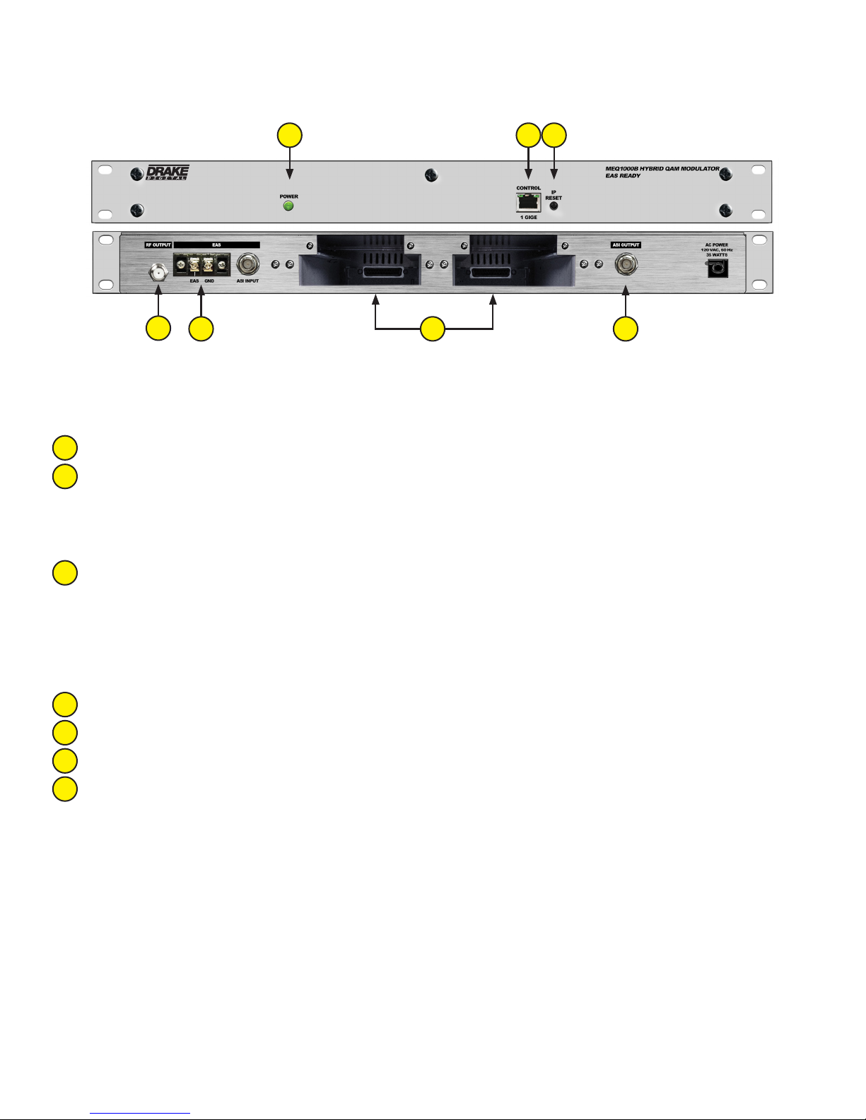
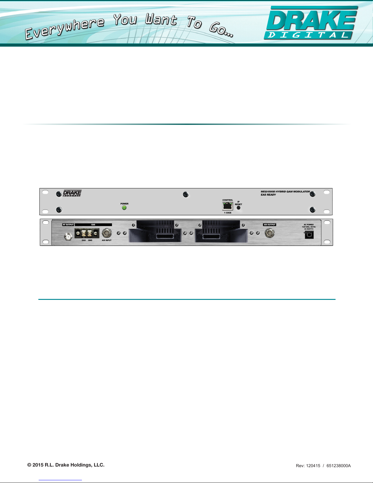
Front and Rear Panel Operation
1 23
4
5 76
FRONT PANEL
1
Ethernet Control: GigE Ethernet wired connection for local and remote management
IP Reset Button: When pressed for >1 seconds, the IP address of the control port will enable to the default factory
2
IP address (172.16.80.1, Subnet Mask 255.255.255.0) The login credentials will also be enabled to the default
username admin and password pass.
Note: The old IP address, login, and password will still be present in the encoder settings.
3
Status LED: The Status LED will blink continually after the IP Reset button has been held and the default IP/
credentials take effect.
Power: The LED is illuminated when the power is ON.
REAR PANEL
4
RF Output: Single QAM channel output @ +61 dBmV maximum and adjustable from 54 to 1002 MHz
EAS input: Supplied via the ASI input and selected by contact closure of EAS terminal.
5
Module Input Slot 1/2: Input Slot 1 on the left and input Slot 2 to the right.
6
ASI Output: Matches RF QAM rate or in ASI only mode may be set from 2 to 100 Mbps
7
10

[This page is intentionally left blank.]
11
 Loading...