

Page 1

MODEL
F R E Q U E N C Y
S Y N T H E S I Z E R
FS-4
INSTRUCTION MANUAL
R.L. DRAKE COMPANY, MIAMISBURG, OHIO, U.S.A.
Page 2

LIMITED WARRANTY
R. L. DRAKE COMPANY warrants to the original purchaser
that this product shall be free from defects in material (except
tubes and RF output transistors) or workmanship for ninety
(90) days from the date of originai purchase.
During the warranty period the R. L. DRAKE COMPANY
or an authorized Drake service facility will provide free of
charge both parts (except tubes and RF output transistors)
and labor necessary to correct defects in material or
workmanship.
To obtain such warranty service, the original purchaser
must:
(1) Complete and send in the Warranty Registration Card.
(2) Notify R. L. DRAKE COMPANY or its nearest authorized
service facility, as soon as possible after discovery of a
possible defect,
(a) The model number and serial number, if any;
(b) The identlty of the seller and the approximate
date of purchase;
(c) A detailed description of the problem, including
details on the electrical connection to associated
equipment and the list of such equipment.
(3) Deliver the product to the R. L. DRAKE COMPANY or the
nearest authorized service facility, or ship the same in its
original container or equivalent, fully insured and
shipping charges prepaid.
Correct maintenance, repair and use are important to obtain
proper performance from this product. Therefore, carefully
read the Instruction Manual. This warranty does not apply
to any defect that R. L. DRAKE COMPANY determines is
due to:
(1) Improper maintenance or repair, including the installation
of parts or accessories that do not conform to the quality
and specifications of the original parts.
(2) Misuse, abuse, neglect or Improper installation.
(3) Accidental or intentional damage.
All implied warranties, if any, terminate ninety (90) days from
the date of the original purchase.
The foregoing costitutes R. L. DRAKE COMPANY'S entire
obligation with respect to this product, and the original
purchaser and any user or owner shail have no other remedy
and no claim for incidental or consequential damages. Some
states do not allow limitations on how long an implied
warranty lasts or do not allow the exclusion or limitation of
incidental or consequential damages, so the above limitation
and exclusion may not apply to you.
This warranty gives specific legal rights and you may also have
other rights which vary from state to state.
540 Richard Street • Miamisburg, Ohio 45342
R. L. DRAKE COMPANY
Page 3

CHAPTER I
INTRODUCTION
1-1. GENERAL DESCRIPTION.
The FS-4 is a frequency synthesizer developed for use with the Drake
Company “4” line equipment. (R-4 series, T-4X series and SPR-4.)
The FS-4 plugs into an unused auxiliary crystal socket in the rear of
the receiver or transmitter, and will supply the various injection signals
to the equipment and allows continuous coverage without utilizing the
accessory crystals.
The frequency readout on the FS-4 displays the received frequency
band, and to this is added the frequency readout of the receiver "PTO"
to obtain the correct received frequency.
The FS-4 supplies ali the crystal oscillator injection signals for the R-4
series and T-4X series in 0.5 MHz steps from 11.1 through 40.6 MHz,
and the readout is direct. An accessory kit is available to provide proper
injection signals for the SPR-4 receiver.
The FS-4 can be used with the 2-C type receiver over the frequency
range of 7 to 30 MHz. When used with the 2-C receiver, the FS-4
frequency read-out is not direct, and a correction factor of “7 Mhz” must
be added to the FS-4 readout to obtain the correct operating frequency.
A special accessory kit is necessary to modify the FS-4 for use with the
2-C receiver.
1-2. MANUAL COVERAGE.
This manual is presented in 5 chapters and is arranged for the
convenience of the operator and service technician as follows:
CHAPTER I Introduction. (Self explanatory.)
CHAPTER II Installation. Describes the procedures to be
followed prior to operation.
CHAPTER III Operation. Illustrates and describes front
panel controls, and describes operation with
Drake receiver/transmitter equipment.
CHAPTER IV
CHAPTER V Maintenance. Provides maintenance and
Theory of Operation. Describes all circuits
and networks.
alignment instructions.
Page 4

CHAPTER II
INSTALLATION
2-1. UNPACKING.
Carefully remove the FS-4 from the shipping carton and examine
it for evidence of damage. If any damage is discovered,
immediately notify the transportation company that delivered the
unit.
NOTE
Fill out the enclosed registration card and return
it to the factory immediately to insure
registration and validation of the warranty.
2-2. LOCATION.
The FS-4 is supplied with a cable approximately 20 inches long
that piugs into the accessory crystal socket of the
receiver/transmitter. This length aliows the user to piace the FS-4
on either side of the receiver/transmitter. Placing the FS-4 on top
of the transmitter is not recommended, due to heat generated
within the transmitter, and the FS-4 will block the air flow.
2-3. POWER REQUIREMENTS.
The FS-4 is shipped from the factory wired for 120 VAC, 50/60
Hz, operation uniess otherwise specified. To operate on 240 VAC
make the proper connections at the transformer on the parent
board as illustrated in figure 2-1.
2-4. FUSE.
The power line is fused for 120 VAC operation with a 3AG Type
1/8 A, Slo-Blo. For 240 VAC operation use a 3AG Type 1/16 A, or
equivalent.
Page 5

Page 6

CHAPTER III
OPERATION
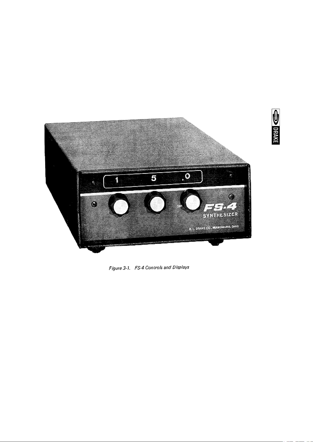
3-1. CONTROLS AND DISPLAYS.
All controls and displays necessary for the operation of the FS-4 are located on the front
panel. The three knobs switch the frequency range in .5 MHz steps and provide direct
frequency display in MHz at the readout directly above each knob. These knobs switch
the frequency in steps of 10 MHz, 1 MHz, and 0.5 MHz from left to right. The 0.5 MHz
knob also turns the FS-4 on and off. Refer to figure 3-1.
3-2. INJECTION CABLE.
The injection cable supplied is used to connect the FS-4 to an unused accessory crystal
socket of the receiver or transmitter. Attach the ground lug to the chassis at the accessory
crystal socket and insert the center pin into the selected accessory crystal socket. The
receiver or transmitter will operate best when the center conductor is connected to the
emitter of the crystal oscillator. This can be determined by noting the S meter reading
or power output readout when the injection cable is plugged into each socket of the
accessory crystal socket.
3-3. BAND SELECT.
When using the FS-4 to control a receiver or transmitter, the receiver/transmitter must
be placed in the proper band as you would in normal use, and the crystal switch must
be placed in the position corresponding with the position selected to plug in the FS-4.
The RF tune (preselector) of the receiver/transmitter must be tuned the same as in normal
use.
3-4. PRESELECTOR SETTING.
A stick-on-decal has been supplied for convenience in locating the positioning of the
RF tune (preselector). This may be applied to the receiver/transmitter front panel by
removing the knob and aligning the decal on the front panel and firmly rubbing it on.
Page 7
Page 8
Caution must be used on proper use of the FS-4 when used with transmitters.
Consult RF Tune calibration charts in the manual of the T-4X series.
3-5 . T UNING A RECEIVER AND TH E FS-4.
a. Switch the FS-4 to the desired operating frequency, as an example:
7.0 for 40 meter amateur band.
b. Place the R-4 Receiver
c. “Xtals” switch in position 10 (assuming the FS-4 is plugged into
accessory crystal socket #10).
d. Set the R-4 “Band” switch to 7.0.
e. Set “PRESELECTOR” control between 5 and 6.
The FS-4 and receiver are now correctly set for proper operation. The rest
of the operating procedure is called out in the receiver/transmitter instruction
manual.
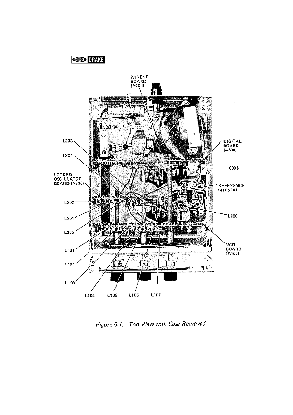
3-6. MODIFICATION OF THE FS-4 FOR USE WITH THE SPR-4 or 2-C.
The FS-4 can be modified from the standard version to operate properly
with the SPR-4 or 2-C by simply removing the case of the FS-4 and
exchanging the reference crystal as shown in figure 5-1, and substituting
the interconnecting cable with one that has a plug which fits the SPR-4
accessory socket. Drill a 1/4" dia. hole in the rear panel of the SPR-4 or 2-C,
and insert grommet. Feed the FS-4 injection cable through this hole to an
unused crystal socket.
The correct reference frequency crystal for the equipment is shown in the
chart below:
Controlled equipment FS-4 Reference Crystal
R-4 and T-4X 9.6 MHz
SPR-4 9,59
2-C 9.5*
*7 MHz must be added to the FS-4 readout for proper operating frequency.
Page 9

The FS-4 should be unplugged from the receiver or transmitter if
operation is desired from internal crystal control and not by use of the
FS-4. The cable capacity of the FS-4 can cause oscillation of the
receiver or transmitter that is not controlled by the selected crystal.
NOTE
No tuning of L406 is required when exchanging the
reference crystal for use with the SPR-4. Some adjustment may be required when exchanging the crystal for use
with the 2-C. See paragraph 5-3, for the proper tuning
procedure.
When using the FS-4 to control the frequency of the 2-C the VFO dial
always reads on the black scale. The red scale does not apply when
using the FS-4.
3-7. FREQUENCY ACCURACY.
All injection frequencies in the FS-4 are derived from the 5 MHz clock
and the reference oscillator. Any frequency error in the injection signal
is essentially the same at any frequency band. When deriving the
injection frequency by use of crystals in the crystal oscillator in the
receiver, as is normally done, the frequency error will vary from band
to band as differ-ent crystals are switched in. This error is compensated
for when the PTO is calibrated.
A difference in frequency may be noted when switching between
standard operate and FS-4 operate. This error is due to crystal errors
as stated above and in generai the use of the FS-4 results in the better
frequency accuracy.
Page 10

CHAPTER IV
THEORY OF OPERATION
4-1. GENERAL.
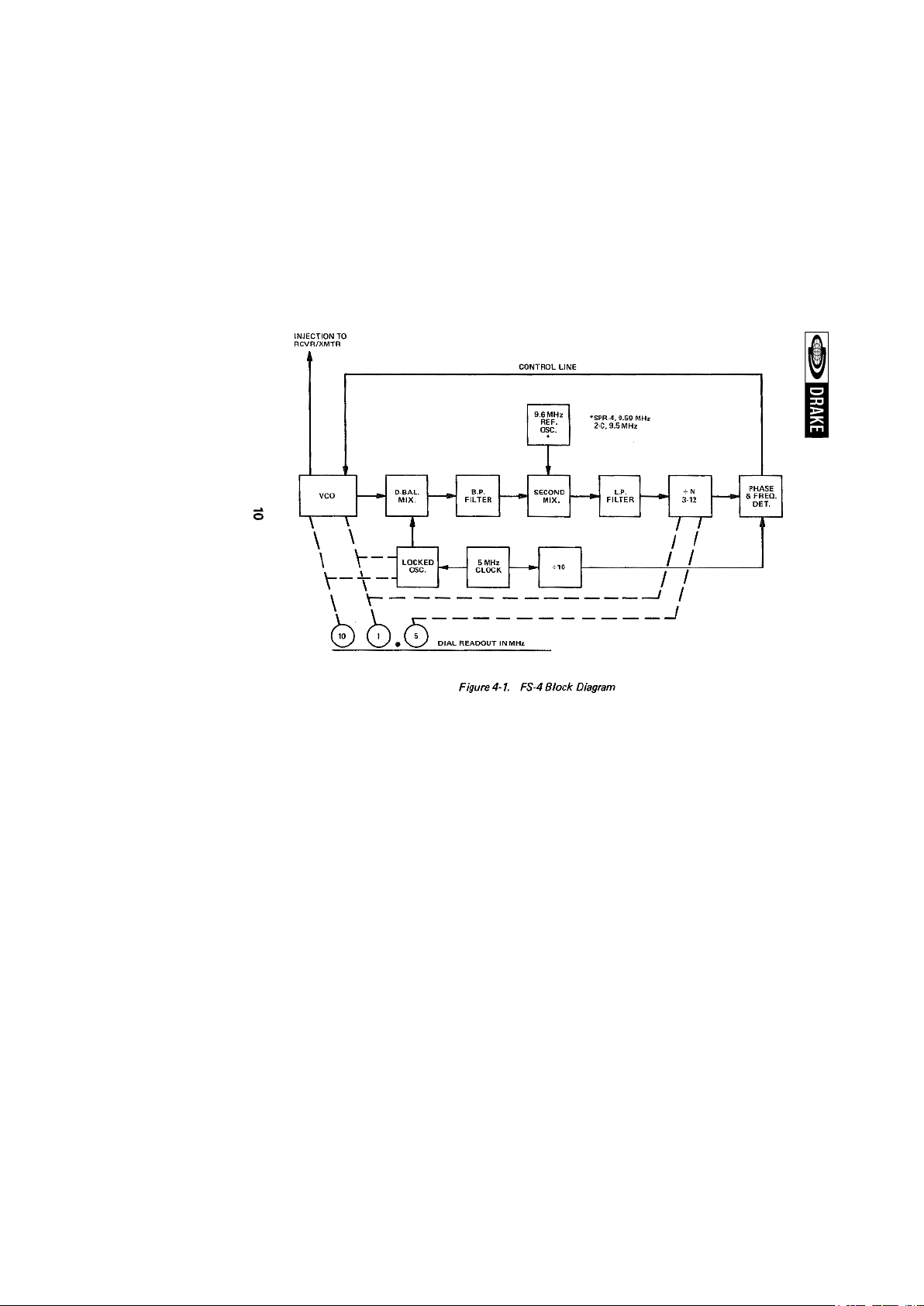
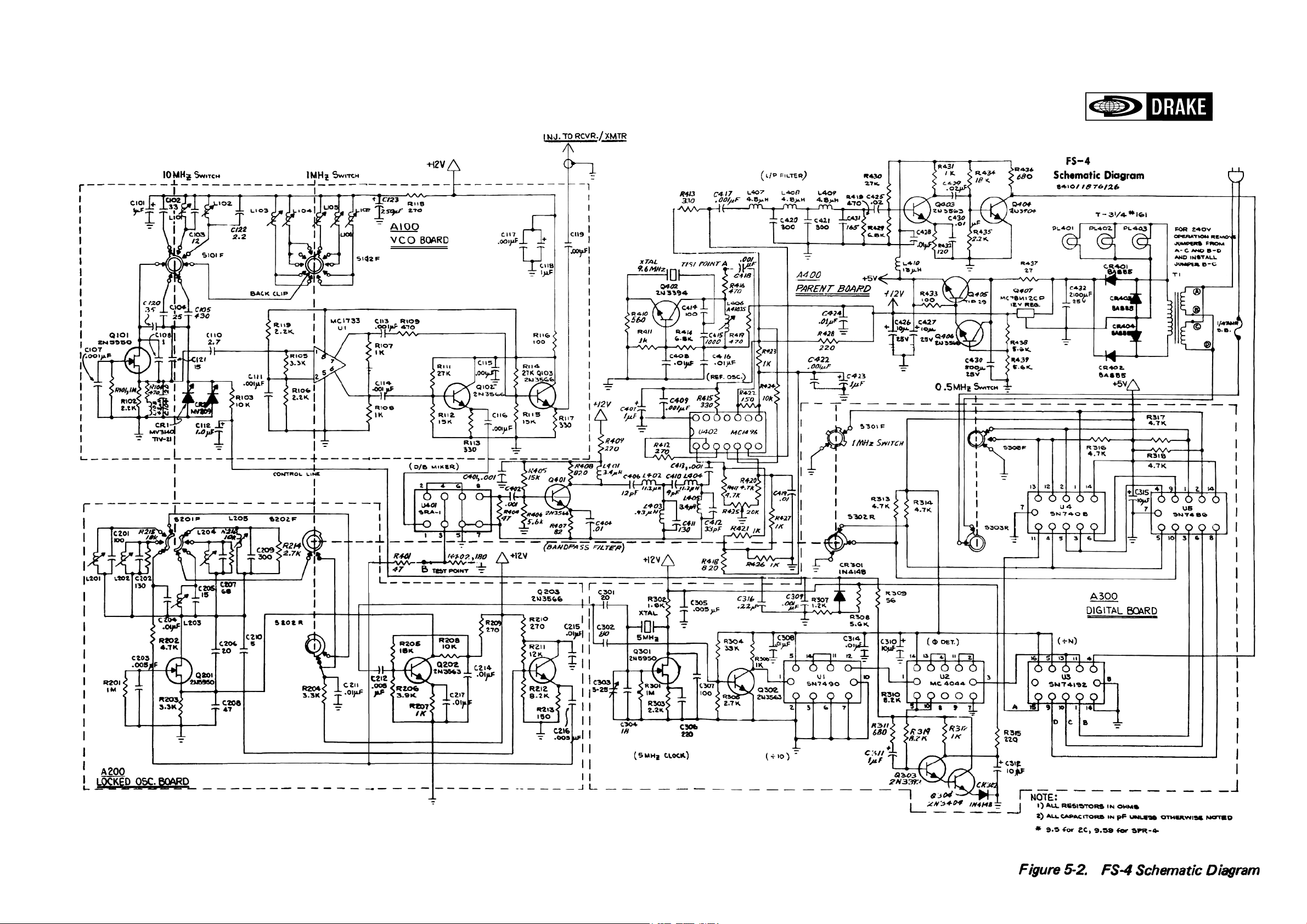
Refer to the block diagram in figure 4-1 for circuit operation.
4-2. VOLTAGE CONTROLLED OSCILLATOR (VCO).
The VCO is a voltage controlled oscillator capable of
operation over the frequency range of 10.5 to 41 MHz, and is
used to provide the crystal oscillator signal required in the
receiver/transmitter for proper operation.
4-3. D-BALANCE MIXER.
A signal from the VCO is applied to the D-Balance Mixer,
where it is mixed with the signal from the locked oscillator to
produce an output in the frequency range of approximately
11 to 16 MHz.
4-4. LOCKED OSCILLATOR.
The locked oscillator develops signals of 5, 10, 15, 20, and
25 MHz which are synchronized to a 5 MHz reference signal.
The actual output of the locked oscillator is determined by the
settings of the front panel switches. The output is zero for
settings of O to 4.5 MHz, 5 MHz for settings of 5 to 9.5 MHz,
etc. This output is mixed with the VCO to produce signals of
11 to 16 MHz which are fed to the bandpass filter.
4-5. BANDPASS FILTER.
The bandpass filter following the D-Balance Mixer
suppresses any higher order products from the mixer as well
as the two inputs and their harmonics.
Page 11
Page 12

4-6. REFERENCE OSCILLATOR.
The output of the bandpass filter is then mixed in the second mixer with
the reference oscillator. The reference oscillator frequency determines
the band edges of the injection output, that is, 16.1 as required in an R-4,
vs. 16.09 for the SPR-4, vs. 16.0 as required by the 2-C (see paragraph
3-6). The resultant output from the second mixer is in the range of 1.5
to 6 MHz and is applied to the low pass filter to suppress any higher
frequency outputs.
4-7. PHASE/FREQUENCY DETECTOR.
The output of the low pass filter is applied to a programmable counter,
which is programmed from the 1 MHz and 0.5 MHz controls, and divides
the input by an appropriate number between 3 and 12 to produce an
output near 0.5 MHz. The output is applied to the phase/frequency
detector, where it is compared in phase and frequency with the resultant
0.5 MHz signal obtained by dividing the 5 MHz clock by 10. An error
signal is developed in the phase/frequency detector which is applied to
a voltage variable capacitor in the VCO, and forces the frequency to be
such that the resultant input to the phase/frequency detector is the same
frequency as that derived from the clock (500 kHz).
4-8. PROGRAMMABLE COUNTER.
The programmable counter is controlled by the 1 MHz and 0.5 MHz
controls, and covers a range count of 10, starting at 3, at dial setting 00.0,
and progressing one count for an increase in the 0.5 position of a two
count for each increase ín the 1 MHz control. The counter increases to 12
at the settíng of 4.5 and then starts over again at 5.0 and repeats every 5
MHz range of the FS-4.
4-9. SIGNALS PRESENT AT DIAL SETTING.
The following is an example of actual signals present for the FS-4
set at a dial setting of 12.5 MHz:
Dial setting = 12.5 MHz
VCO Frequency = 23.6
Locked Oscillator = 10 MHz
D-Bal. Mixer Output = 23.6 -10 = 13.6
Second Mixer Output = 13.6 -9.6 = 4
÷ N = 8
÷ N output = 4/8 = 0.5
Page 13

CHAPTER V
MAINTENANCE
5-1. ALIGNMENT.
The FS-4 has been carefully aligned and tested at the factory for proper
operation and should not be realigned unless required and then only by
a knowledgeable and competent technician.
5-2. 5 MHz CLOCK ALIGNMENT.
Tune in and zero beat a signal from WWV using the internal crystal of the
receiver. Without moving the frequency dial of the receiver, couple the
receiver antenna to the FS-4 case or ground. Tune capacitor C303 for
zero beat on the receiver. Refer to figures 5-1 and 5-2.
NOTE
A higher frequency of WWV signal provides greater
accuracy, as the above process provides tuning of the 5
MHz clock by tuning in a harmonic.
5-3. REFERENCE OSCILLATOR ALIGNMENT.
For a high degree of accuracy the reference oscillator should be tuned
using a frequency counter connected to the injection output of the FS-4.
Set the FS-4 dial to 00.0 and tune L406 for 11.1 MHz.
NOTE
If using a reference other than 9.6 MHz, tune the injection
output frequency 1.5 MHz above the reference crystal
frequency as specified in paragraph 3-6.
This oscillator may be tuned for operation with very little frequency error
merely by tuning for maximum RF voltage measured at test point A on
bottom of parent board.
NOTE
It is not necessary to realign the oscillator when
changing the crystal as specified in paragraph 3-6.
Page 14
Page 15

5-4. LOCKED OSCILLATOR ALIGNMENT.
Tune the indicated coils for maximum RF output voltage measured at test
point B (on bottom of parent board) when the FS-4 is tuned to the indicated
dial setting:
DIAL SETTING Mhz TUNE COIL
50
10.0
150
200 L201
250
L205
L202
L204
L203
5-5. VOLTAGE CONTROLLED OSCILLATOR ALIGNMENT.
The VCO may be tuned using a frequency counter connected to the
injection output of the FS-4. If the system is operational on most dial
settings, the oscillator may be aligned by monitoring the control line voltage
under locked conditions.
FREQUENCY COUNTER METHOD.
Disconnect the control line cable at the VCO board and apply a well filtered
DC voltage of 1.5 V to the control line input of the VCO. (This may be
obtained by using a potentiometer of at least 5 k Ohm connected across
the 12 volt supply to ground.) Tune the oscillator for the indicated frequency
when tuned to the specified setting:
DIAL SETTING TUNE COIL FREQUENCY
00.0 L105 10.6 MHz
01.0 L106 11.6 MHz
03.0 L107 13.6 MHz
05.0 L103 15.6 MHz
07.0 L104 17.6 MHz
10.0 L101 20.6 MHz
20.0 L102 30.6 MHz
Page 16

LOCKED LOOP METHOD.
If the FS-4 is operational on most frequencies, the VCO may be
tuned by monitoring the voltage at the control line under locked
conditions. Do not disconnect the control line as in the method
above. Connect a DC volt meter to the control line at the VCO
board and tune the indicated coil for the specified control line
voltage:
DIAL SETTING TUNE COIL CONTROL LINE VOLTAGE
0,0 L105 2.9 V DC
1,0 L106 2.7 V DC
3,0 L107 2.4 V DC
5,0 L103 2.3 V DC
7,0 L104 2.3 V DC
10,0 L101 3.0 V DC
20,0 L102 2.6 V DC
Page 17

NOTES
Page 18
DRAKE AMATEUR P RODUC TS
R-4C Receiver, covers the 160 meter through 10 meter amateur
T-4XC Transmitter, covers the 160 through 10 meter amateur
TR-4C Transceiver, 300 Watt high frequency single-sideband unit
L-4B Linear Amplifier, built for continuous duty at full capacity.
SPR-4 An all solid-state communications receiver which can be
FS-4 Frequency Synthesizer, built for use with R-4 series, SPR-4,
MN-4 Antenna Matching Network, matches 50 Ohm transmitter
MN-2000 Antenna Matching Network. Same as MN-4 except: 1000 Watts
W-4 Wattmeter, reads forward and reflected power directly in
W V-4 Wattmeter, reads forward and reflected power directly in
TR-33C Transceiver, 2 meter VHF-FM, portable. Twelve channels,
R CS-4 Remote Coax Switch, provides remote selection of up to
SSR-1 General Coverage Receiver, 0.5-30 MHz continuous. All
solid state.
For information on any of our products, please feel free to write our Sales
Department, 540 Richard Street, Miamisburg, Ohio 45342 or call direct,
513-866-2421.
bands and up to fifteen additional 500 kHz ranges. It has
8-pole crystal filter selectivity with passband tuning and
transceives with the T-4XC with excellent sensitivity.
bands and most other frequencies between 1.5 and 30
MHz. It has 8-pole crystal filters for sideband selection.
It may be used to transceive with the R-4C
covers the 80 meter through 10 meter amateur bands.
Includes AM and CW modes, a linear, permeability-tuned
VFO and two 8-pole crystal lattice filters.
2000 Watts PEP on SSB. 1000 Watts on AM, CW and RTTY.
Covers the 80 meter through 10 meter bands.
programmed with accessory crystals to cover 150 kHz to 30
MHz. The SPR-4 receives AM, CW, SSB, (upper and lower)
and may be powered from 120 VAC, 240 VAC, and 12 VDC.
2-C receivers, and T-4X series transmitters.
output to coax antenna feedline with VSWR up to 5:1. An
integrai Wattmeter reads forward power in Watts and
VSWR directly. 200 Watts continuous duty output.
continuous duty output (2000 Watts PEP) and 3 antenna
connectors switch-selectable from front panel.
Watts (VSWR from nomograph). Range: 200 and 2000
Watts full scale, 1.8 to 54 MHz.
Watts (VSWR from nomograph). Range: 100 and 1000
Watts full scale, 20 to 200 MHz.
self-contained batteries and attached microphone.
five antennas, using only one main feedline. Allows
grounding of unused antennas. Motor driven switches
controlled from station located console.
Page 19
Page 20

 Loading...