

Page 1
All health and safety procedures and recommendations must be followed as detailed in the Horizon Compact + User Manual.
This product is to be installed and maintained by experienced telecommunications personnel only. Installations must adhere to specifications listed in the Horizon Compact+ User Manual.
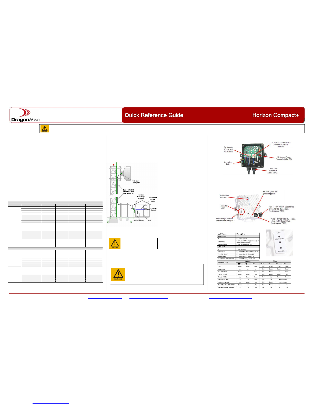
Horizon Compact+ is to be installed with proper grounding, Horizon PonE surge arrestor and 48 v power connected through the Horizon PonE according to instructions in the Horizon Compact+ User Manual
Customer Support International Help Desk: +1 613 271 7010 email: [email protected] web: http://support.dragonwaveinc.com DragonWave Inc. http://www.dragonwaveinc.com 83-000089-01-02-01
Mechanical
Radio/Modem (no antenna) 10.2 cm x 24.3 cm x 22.1 cm; 3.4 kg / 4 in x 9.6 in x 8.7 in; 7.5 lbs
Power, Connections, Payload
Operating Temperature -40°C to + 50°C (-40°F to +122° F)
With Heat Shield -40°C to + 60°C (-40°F to +140° F)
Humidity 100 % Condensing
Input -40.5 VDC to -56 VDC (-48 VDC nominal), 110/240 VAC (Opt.)
Consumption (per link end) 43 - 80 Watts depending on RF frequency
Power -48V, PonE, or Direct DC
Payload (+ Inband NMS) Shielded RJ45 or optical LC, 1000/100/10 BaseT
Interface 2x10/100/1000bT, or 4x10/100bT, or 1x10/100/1000bT plus 2x
10/100bT
Latency GigE <200μs, Typical 120μs GigE
Base Capacity Variable: 10 to 800 Mbps full duplex CIR
Frame Size 64 to 9600 Bytes
Flow Control Yes
Prioritization 8 levels with 8 queues ; 802.1p/q, MPLS, DSCP ToS Bits
Modulation Shifting Yes, Hitless
Network Management (NMS)
SNMP SNMP Traps, Enterprise MIB, SNMP v1, v2c and v3
EMS DragonVision, SSL, HTTP,SSH, Radius
LLDP Supported by DragonVision Element Manager
Channel BW, Throughput, Tx Power, Rx Sensitivity
The table below shows examples for two18 GHz Radio Bands.
18 GHz FCC/IC Radio Band
Bandwidth
Modulation
Throughput
Tx Power
Rx Sensitivity
Rx Saturation
50 MHz
QPSK PTCM2
66
23.7
-83.2
-13.1
64QAM PTCM2
241
20.0
-69.4
-20.0
256QAM PTCM2
329
19.5
-53.4
-23.0
256QAM 1
351
19.5
-61.0
-24.3
40 MHz
QPSK PTCM2
52
23.7
-84.2
-13.1
64QAM PTCM2
192
20.0
-70.4
-20.0
256QAM PTCM2
262
19.5
-64.4
-23.0
256QAM 1
279
19.5
-62.0
-24.3
QPSK PTCM2
39
23.7
-85.5
-13.1
64QAM PTCM2
144
20.0
-71.7
-20.0
256QAM PTCM2
196
19.5
-65.7
-23.0
256QAM 1
209
19.5
-63.2
-24.3
20 MHz
QPSK PTCM2
26
23.7
-87.3
-13.1
64QAM PTCM2
94
20.0
-73.5
-20.0
256QAM PTCM2
129
19.5
-67.5
-23.0
256QAM 1
137
19.5
-65.0
-24.3
10 MHz
QPSK PTCM2
12
23.7
-90.6
-13.1
64QAM PTCM2
44
20.0
-76.8
-20.0
256QAM PTCM2
60
19.5
-70.8
-23.0
256QAM 1
64
19.5
-68.4
-24.3
18 GHz ETSI/ITU Radio Band
55/56 MHz
QPSK PTCM2
71
23.7
-82.9
-13.1
64QAM PTCM2
261
20.0
-69.1
-20.0
256QAM PTCM2
356
19.5
-63.1
-23.0
256QAM 1
380
19.5
-60.6
-24.3
28/27.5
MHz
QPSK PTCM2
38
23.7
-85.7
-13.1
64QAM PTCM2
138
20.0
-71.9
-20.0
256QAM PTCM2
188
19.5
-65.9
-23.0
256QAM 1
201
19.5
-63.4
-24.3
14/13.75
MHz
QPSK PTCM2
19
23.7
-88.7
-13.1
64QAM PTCM2
68
20.0
-74.9
-20.0
256QAM PTCM2
93
19.5
-68.9
-23.0
256QAM 1
99
19.5
-66.5
-24.3
7 MHz
QPSK PTCM2 9 23.7
-91.7
-13.1
64QAM PTCM2
34
20.0
-77.9
-20.0
256QAM PTCM2
47
19.5
-71.9
-23.0
256QAM 1
50
19.5
-69.5
-24.3
Installation Requirements
Installation kits include the following: 2 x PonE power/surge units
2 x Grounding Kits with cable and bolts
AC option – 2 x AC/DC power converter and cables
AC/DC Option – 1 x AC power adapter
2 x weather caps for unused physical port
2 x Ethernet cable splitter/combiner
Cables
Shielded, outdoor rating, Cat5E cables are
required on the unprotected side (to Horizon).
Recommended cable: Belden 7919A. Shield
must be connected to metal shell of RJ45
connectors at both ends of cable!
Unshielded Cat5E cables and/or RJ45
connectors are required on protected side of
PonE unit (to Network). Cat5E cables may be
supplied by the customer, or ordered from
DragonWave.
Power cable: 2-wire 16 AWG
Mounting Masts and Twist &
Sway
Minimim 2 3/8” OD thick walled (SKD-80) mast
for 30 cm and 60 cm antennas.
Minimum 3” OD thick walled mast for 90 cm
and 120 cm.
Minimum 4” OD thick walled mast for 180 cm.
Maximum angular twist is ½ of the beamwidth.
Grounding, Power and Lightning Protection
There is one grounding point available on the
Horizon Compact casing (see diagram under
“Ports”). Use 6 AWG wire (minimum) to
connect the casing to lightning protection
system (LPS) grounding conductors, or
structure ground. Use shortest length, avoiding
loops and sharp bends.
When configured with a copper interface, power and network connections are fed to the Horizon via a
proprietary Power-on-Ethernet (PonE) power injector and surge arrestor
The power injector supports redundant -48 V DC power feeds and protects the power supply
and network from power transients created by lightning or other sources.
Ports
Port 1 and Port 2 may be configured as two 100/10 Base-t (Fast Ethernet) ports, or as single
1000/100/10 Base-t (Gigabit) ports. Any of the 4 possible ports may be configured for in-band or
out-of-band management. Power is fed to Port 1 for copper interface or Port 2 for fibre interface.
BNC Field strength monitoring port is for alignment purposes.. Also used for redundancy switching
applications.
LED Indicators
Device must be effectively
grounded / earthed in order to
protect against lightning strikes
and surges
The Power Injector/Surge Arrestor MUST be mounted as close as possible to,
and above, the building entry point (BEP) and its external grounding lug must be
connected to the nearest lightning (LPS) ground with #6 AWG (minimum)
grounding wire, avoiding loops and sharp bends.
DO NOT connect the grounding lug to AC power supply wiring ground!
DO NOT mix AC power supply option with site-supplied 48 VDC!
DO NOT connect the network to the RJ-45 connectors marked
“TO HORIZON UNPROTECTED”. Damage to switches or routers may result
Page 2
All health and safety procedures and recommendations must be followed as detailed in the Horizon Compact + User Manual.
This product is to be installed and maintained by experienced telecommunications personnel only. Installations must adhere to specifications listed in the Horizon Compact+ User Manual.
Horizon Compact+ is to be installed with proper grounding, Horizon PonE surge arrestor and 48 v power connected through the Horizon PonE according to instructions in the Horizon Compact+ User Manual
Customer Support International Help Desk: +1 613 271 7010 email: [email protected] web: http://support.dragonwaveinc.com DragonWave Inc. http://www.dragonwaveinc.com 83-000089-01-02-01
Logging In
Super User: Default username is energetic Default password is wireless.
Default IP Address: 192.168.10.100 subnet mask 255.255.0.0
By default, management is through Horizon Compact+ Port 1 (in-band).
Configure your PC with the same IP address range and subnet.
Command Line Interface (CLI) Overview
The majority of commands begin with either set or get.
Context sensitive help: enter a partial command followed, or preceded, by “?”.
Example 1: set radio ? returns a list of all commands that start with set radio
Example 2: ? radio returns all commands that include the word “radio”
Pressing the Tab key after entering a partial command will complete that command
The up and down arrows (↑ and ↓) will recall previously input command lines (up to 20).
An unrecognized CLI entry will be acknowledged with NAK.
Once configuration changes have been completed, issue save mib command. Some changes
require reset system to invoke changes. Resetting the system is traffic affecting.
Web Interface
Enter Horizon Compact+ IP address as the URL in Web browser to access Horizon Web interface.
Configuration Steps
1. Configure Radio Parameters
set radio config
Allows you to configure: radio band, system mode, programmed frequency.
2. Unlicensed only – select antenna size (automatically sets the maximum allowed power)
a. get antenna diameter to display available sizes and associated index
b. set antenna diameter <index>
3. Configure IP parameters
set ip config (for management of Horizon Compact+)
Allows you to configure: IP address, subnet mask, default gateway
You have the option of having the changes made effective immediately, or after a system
reset.
WARNING:
The above commands may be used to change the radio configuration of an existing working
link. If management of the far end Horizon Compact+ is only via the radio link, then configure
the far end radio first. Otherwise, if you configure the near end radio first, you will lose the link
to the far end radio and be unable to configure it. If you change IP settings you may have to
reconfigure your management device (e.g.PC) in order to communicate with the Horizon
Compact+.
Advanced Configuration Parameters
There are a number of parameters that can be configured to provide advanced features:
Up/Downgrade Licensed Features*
Adaptive Tx Power Control *
Event and Performance Logs*
Configuring Ethernet Ports 1 and 2 *
Authentication *
Radio and Network Loopback*
RADIUS Server User Authentication *
Threshold Alarms *
Network Management*
Management VLAN Tagging *
Rapid Link Shutdown (RLS) *
Editing System Config Files*
Quality of Service (QoS) *
Configuring (SNTP) *
EOAM **
Pause Frames *
Adaptive Modulation *
LLDP **
Bandwidth Management *
System Management*
ECFM **
System redundancy *
X2 – Bandwidth Doubling *
Detailed configuration information for each can be found in the Horizon Compact+ Product Manual
* Volume 2 - Advanced Features ** Volume 4 - Networking Features
Antenna Alignment
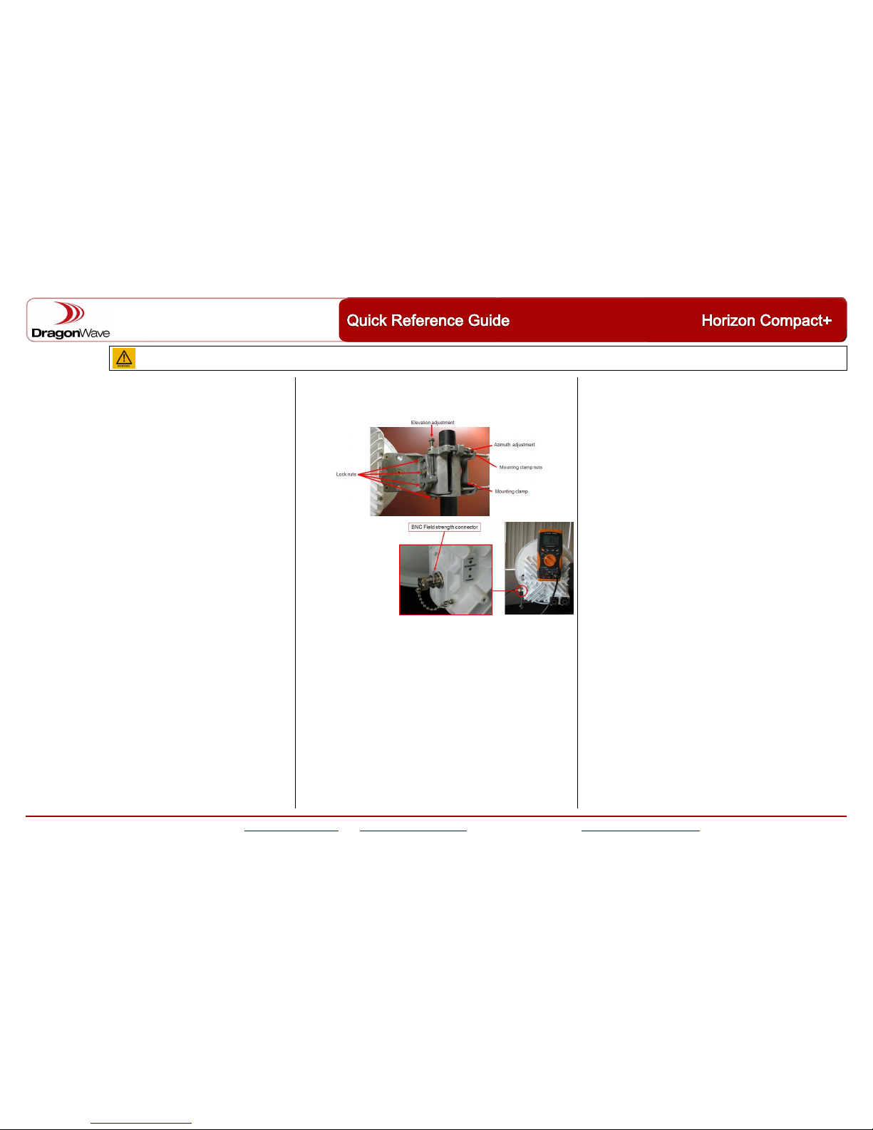
Loosen the bolts clamping the mounting bracket to the post sufficiently to allow the mounting
bracket assembly to be rotated on the post, or tower, by hand. Visually align with the far end
installation. Use a compass or landmarks to verify the bearing where the opposite end is difficult to
identify. When visually aligned, re-clamp the mounting assembly to the pole.
Enable BNC : set alignment on
Enter
Loosen the antenna mount fine
azimuth and elevation adjustment
lock nuts.
Connect a voltmeter (1 mV = 1
dB) to the field strength
monitoring port (BNC) and adjust
the fine azimuth and elevation
adjustments for a maximum
signal.
Identify all side lobes plus the
main lobe. Ensure that you are
aimed at the main signal lobe.
The final received signal strength (RSL) should be within ±3 dB of the link budget figure.
Once alignment is achieved, tighten the lock nuts on the adjustment mechanisms.
Disable BNC : set alignment off Enter-
Alignment Adjustment Sensitivity
When performing fine alignment adjustments it is important to rotate the adjustment nuts 1/10th
of a turn at a time between taking RSL readings.
The beam width of a Horizon Compact+ system is typically no greater than 2 degrees. One
complete turn of a fine adjustment screw/nut may move the system right through the peak
signal position.
Indications of a Properly Operating Link
No alarms – get alarms
RSL within ±3 dB of link budget figure – get modem statistics
Eb/No ≥ 19 dB – get modem statistics
Signal to Noise Ratio (SNR) ≥24 dB – get modem statistics
Equalizer Stress typically 30, but < 150 – get modem statistics
Modem Block Error Rate 0.00e+00 – get traffic statistics
All sections operational – get health
System Redundancy
• Hot stand-by with or without DPRM
• X2 - Bandwidth doubling with or without DPRM.
Please refer to Horizon Compact+ Product Manual for details.
Troubleshooting
Alarms: Check alarms. No alarms should be present.
Modem Receiver Loss of Signal = no signal being received from the far end.
Radio Mismatch = incorrect radio band configured, TxH / TxL reversed, or incorrect radio
Ethernet Link Down = no connectivity on Ethernet link
Modem Hardware Fault = replace Horizon unit
Radio Power Amp = replace Horizon unit if alarm counts are increasing
Synthesizer Unlock = replace Horizon unit if alarm is consistent
RSL Issues:
Mismatched RSL between endpoints
- one endpoint at target RSL, other endpoint low RSL: use RF loopback feature to
determine if Transmitter at one end, or Receiver at other end is at fault.
- Verify both ends are receiving DC power
Low RSL both endpoints
- Verify clear LOS exists
- Verify alignment
- Verify Transmit power at both ends
- Link fade?
- Polarization is the same at both ends?
Poor RF Signal Quality:
- See parameters in “Indications of a Properly Operating Link”
Packet Loss, Poor Throughput, Loss of IP Connectivity:
- check RF signal quality
- check for mismatched modulation between endpoints
- check Ethernet switch traffic statistics at both ends of the link
- verify Ethernet speed and duplex settings
- check COS/QOS settings
- check integrity of Ethernet cables
Merlin Utilities – Contact DragonWave Technical Support
- System diagnostics
- Reset to factory default settings (Super User etc.)
- Serial number retrieval
- Bulk software upgrades
 Loading...