

Page 1

Horizon COMPACT
TM
Wireless Ethernet
Release 1. 01.01
Product Manual - Volume 1
Version 1.4
Page 2

Page 3

NOTICE
This document contains confidential information, which is proprietary to DragonWave. No part of its
contents can be used, copied, disclosed, or conveyed to any party in any manner whatsoever without
prior written permission from DragonWave Inc.
Copyright © 2001-2008 DragonWave Inc.
Horizon Compact Release 1. 01.01 Wireless Ethernet Product User Manual – Volume 1
Page 4

Table of Contents
1.0 U SER MANUAL STRUCTURE............................................................................1
2.0 INTRODUCTION TO HORIZON COMPACT..............................................................1
2.1 APPLICATIONS..........................................................................................................................2
2.1.1 WI MAX...........................................................................................................................2
2.1.2 3G CELLULAR BACKHAUL / ETHERNET EVOLUTION .................................................................2
2.1.3 LEASED LINE REPLACEMENT ..............................................................................................2
2.1.4 LAST MILE FIBRE EXTENSION .............................................................................................2
2.2 T ECHNICAL SPECIFICATIONS.......................................................................................................3
3.0 PHYSICAL DESCRIPTION.................................................................................5
3.1 CABLING .................................................................................................................................6
3.1.1 COPPER INTERFACE................................ ..........................................................................6
3.1.2 OPTICAL INTERFACE................................ ..........................................................................6
3.2 LIGHTNING PROTECTION............................................................................................................7
3.3 DUAL POLARITY RADIO MOUNT (DPRM) ................................ ......................................................7
3.4 POWER SWITCH RADIO MOUNT (PSRM) ......................................................................................8
4.0 INSTALLATION REQUIREMENTS........................................................................9
4.1 HOISTING LUG........................................................................................................................10
4.2 ETHERNET CABLING FROM HORIZON TO ETHERNET SWITCH..........................................................11
4.3 ASSEMBLING THE RJ-45 CONNECTOR........................................................................................12
4.3.1 “SNAP FIT” STYLE................................ ............................................................................12
4.3.2 “PUSH FIT” STYLE................................................................ ............................................13
5.0 POWERING THE HORIZON COMPACT ............................................................... 15
5.1 COPPER INTERFACE................................ ................................................................................15
5.2 OPTICAL INTERFACE................................ ................................................................................16
6.0 INITIAL CONFIGURATION...............................................................................19
6.1 LOGGING ON.......................................................................................................................... 19
6.1.1 USING TELNET ...............................................................................................................19
6.1.2 CONTEXT SENSITIVE HELP ............................................................................................... 19
6.1.3 USING THE WEB INTERFACE.............................................................................................20
6.2 CONFIGURING RADIO BAND AND F REQUENCY CHANNELS..............................................................20
6.2.1 USING TELNET ...............................................................................................................20
6.2.2 USING THE WEB INTERFACE.............................................................................................21
6.3 CONFIGURING IP ADDRESS VALUES .......................................................................................... 22
6.3.1 USING TELNET ...............................................................................................................22
6.3.2 USING THE WEB INTERFACE.............................................................................................22
6.4 RECOVERY OF IP ADDRESS AND SERIAL NUMBERS......................................................................23
6.5 CHANGING AND ADDING USER NAMES AND PASSWORDS...............................................................23
6.5.1 CHANGING THE SUPER USER NAME AND PASSWORD............................................................23
Horizon Compact Release 1. 01.01 Wireless Ethernet Product User Manual – Volume 1
Page 5

Table of Contents
6.5.2 ADDING OR CHANGING NOC USER ACCOUNTS.....................................................................24
6.5.3 ADDING OR CHANGING ADMIN USER ACCOUNTS..................................................................26
6.6 LOGGING OUT................................ ........................................................................................27
6.6.1 SESSION T IME OUT.........................................................................................................27
7.0 A NTENNA MOUNTING AND TOWER SPECIFICATIONS............................................ 29
7.1 POLARITY ..............................................................................................................................29
7.1.1 LICENSED RADIO BANDS..................................................................................................29
7.1.2 UNLICENSED RADIO BANDS (UL24) ................................................................................... 30
7.2 ANTENNA LOCATION ................................................................ ................................................31
7.3 POLE AND TOWER SPECIFICATIONS...........................................................................................32
8.0 G ROUNDING, POWER AND SURGE ARRESTORS .................................................33
8.1 POWER ON ETHERNET (PONE) .................................................................................................34
9.0 PREPARING FOR ALIGNMENT.........................................................................37
9.1 RECEIVED SIGNAL LEVEL (RSL) MEASUREMENTS................................................................ ........38
9.2 T HREE IMPORTANT FACTORS....................................................................................................39
9.2.1 ANTENNA RADIATION PATTERNS.......................................................................................39
9.2.2 CLEAR LINE OF SIGHT (LOS) ............................................................................................ 39
9.2.3 ALIGNMENT ADJUSTMENT SENSITIVITY ...............................................................................39
10.0 A LIGNING THE ANTENNAS.............................................................................41
10.1 SIGNS OF A HEALTHY LINK...................................................................................................42
11.0 A DVANCED CONFIGURATION FEATURES ..........................................................43
11.1 RADIUS SERVER USER AUTHENTICATION..............................................................................43
11.2 MANAGEMENT VLAN TAGGING.............................................................................................44
11.3 802.1P PRIORITY QUEUING IMPLEMENTATION IN HORIZON COMPACT.........................................44
11.3.1 OPERATION WITH 802.1P PRIORITY QUEUING DISABLED .......................................................45
11.3.2 OPERATION WITH 802.1P PRIORITY QUEUING ENABLED .......................................................45
11.3.3 EXPEDITE QUEUES.........................................................................................................45
11.3.4 MANAGEM ENT TRAFFIC....................................................................................................45
11.4 PAUSE FRAMES..................................................................................................................46
11.5 HORIZON COMPACT THROUGHPUT SPEED ..............................................................................46
11.5.1 MAXIMUM THROUGHPUT SPEED ........................................................................................ 46
11.6 ADAPTIVE T RANSMIT POWER CONTROL (ATPC) ......................................................................47
11.7 HORIZON COMPACT AUTHENTICATION ................................ ....................................................48
11.8 T HRESHOLD ALARMS...........................................................................................................49
11.9 RAPID LINK SHUTDOWN .......................................................................................................49
11.10 CONFIGURING THE TIME SOURCE (SNTP) ..............................................................................49
11.11 AUTOMATIC ADAPTIVE MODULATION (AAM) ................................................................ ............50
11.12 HORIZON COMPACT THROUGHPUT DOUBLING......................................................................... 51
11.13 HORIZON REDUNDANCY .......................................................................................................51
iii
Horizon Compact Release 1. 01.01 Wireless Ethernet Product User Manual – Volume 1
Page 6

DragonWave Inc.
iv
11.13.1 BNC CONNECTOR......................................................................................................51
11.13.2 T WO WIRE OPTION .....................................................................................................52
11.13.3 SINGLE WIRE OPTION WITH THE PSRM..........................................................................54
12.0 H ORIZON MANAGEMENT ...............................................................................57
12.1 IN-BAND AND OUT-OF-BAND MANAGEMENT.............................................................................57
12.1.1 MANAGEMENT THROUGH PORT 1 (IN-BAND) ................................ ........................................57
12.1.2 MANAGEMENT THROUGH PORT 2 (OUT-OF-BAND).................................................................58
12.2 T ELNET ACCESS.................................................................................................................58
12.3 SECURE SHELL ACCESS SECURITY........................................................................................58
12.4 SUPPORTED SNMP VERSIONS.............................................................................................58
12.5 WEB INTERFACE................................................................................................................. 59
12.5.1 HOME SCREEN ...............................................................................................................59
12.5.2 PERFORMANCE SCREEN ..................................................................................................60
12.5.3 CONFIGURATION SCREEN ................................ ................................................................60
12.5.4 DIAGNOSTICS SCREEN ................................ ....................................................................60
12.5.5 ALARMS SCREEN ................................................................................................ ............61
12.5.6 T OOLS SCREEN.............................................................................................................. 61
12.5.7 CONTACTS SCREEN ........................................................................................................61
12.6 HORIZON COMPACT SSL WEB SERVER..................................................................................61
12.6.1 GENERATING A CERTIFICATE ON HORIZON COMPACT ........................................................... 61
12.7 EVENT AND PERFORMANCE LOGS.........................................................................................62
12.8 RADIO LOOPBACK............................................................................................................... 62
12.9 ALARMS LIST.....................................................................................................................63
13.0 C ONFIGURATION BACKUP AND RESTORE.........................................................65
13.1 SYSTEM CONFIGURATION BACKUP................................ ........................................................65
13.2 SYSTEM CONFIGURATION RESTORE......................................................................................65
13.3 USER ACCOUNT CONFIGURATION BACKUP..............................................................................65
13.4 USER ACCOUNT CONFIGURATION RESTORE............................................................................65
14.0 SOFTWARE UPGRADES ................................................................................67
14.1 SINGLE SYSTEM .................................................................................................................67
14.2 MULTIPLE SYSTEMS................................................................................................ ............67
A PPENDIX A – LIST OF CLI COMMANDS .................................................................... 69
A PPENDIX B – SAFETY INFORMATION .......................................................................71
A PPENDIX C - REGULATORY COMPLIANCE INFORMATION .............................................. 75
Horizon Compact Release 1. 01.01 Wireless Ethernet Product User Manual – Volume 1
Page 7

Table of Contents
v
List of Figures
F IGURE 2-1 HORIZON COMPACT - COPPER INTERFACE VARIANT..................................................................5
F IGURE 2-2 HORIZON COMPACT LED INDICATORS.....................................................................................5
F IGURE 2-3 DUAL POLARITY RADIO MOUNT.............................................................................................7
F IGURE 3-1 HORIZON COMPACT INSTALLATION .......................................................................................10
F IGURE 3-2 HOISTING LUGS.................................................................................................................10
F IGURE 3-3 PONE AND RJ-45 CONNECTIONS FOR HORIZON .....................................................................11
F IGURE 3-4 RJ-45 CABLE CONNECTOR “SNAP FIT” STYLE .......................................................................12
F IGURE 3-5 RJ-45 CABLE CONNECTOR “PUSH FIT” STYLE .......................................................................13
F IGURE 4-1 CONNECTING POWER TO THE HORIZON COMPACT – COPPER INTERFACE................................ ....15
F IGURE 4-2 CONNECTING POWER TO THE HORIZON COMPACT – OPTICAL INTERFACE...................................16
F IGURE 4-3 RJ-45 CONNECTOR PINOUT – PORT 2 MANAGEMENT...............................................................17
F IGURE 6-1 HORIZON COMPACT SHOWING CLIP MOUNT FEATURES.............................................................29
F IGURE 6-2 HORIZON COMPACT POLARITY MARKER.................................................................................30
F IGURE 6-3 RECOMMENDED ANTENNA PLACEMENT.................................................................................31
F IGURE 7-1 HORIZON COMPACT CASE GROUNDING POINT.........................................................................33
F IGURE 7-2 SURGE ARRESTOR AND POWER INTEGRATOR ......................................................................... 35
F IGURE 7-3 ETHERNET CABLE CLIP.......................................................................................................35
F IGURE 8-1 MOUNTING BRACKET WITH FINE ADJUSTMENT BOLTS...............................................................37
F IGURE 8-2 VOLTMETER CONNECTIONS TO BNC FIELD STRENGTH MONI TORING CONNECTOR .........................38
F IGURE 10-1 DPRM AND THROUGHPUT DOUBLING.................................................................................51
F IGURE 10-2 REDUNDANCY CONNECTIONS – 2 WIRE OPTION – COPPER INTERFACE...................................... 52
F IGURE 10-3 REDUNDANCY CONNECTIONS – 2 WIRE OPTION – OPTICAL INTERFACE...................................... 53
F IGURE 10-4 REDUNDANCY CONNECTIONS – SINGLE WIRE OPTION – COPPER INTERFACE..............................54
F IGURE 10-5 REDUNDANCY CONNECTIONS – SINGLE WIRE OPTION – OPTICAL INTERFACE............................. 55
F IGURE 11-1 WEB INTER FACE - HOME SCREEN ....................................................................................... 59
F IGURE 11-2 RADIO LOOPBACK...........................................................................................................62
Horizon Compact Release 1. 01.01 Wireless Ethernet Product User Manual – Volume 1
Page 8

DragonWave Inc.
vi
List of Tables
TABLE 2-1 HORIZON LED OPERATION .....................................................................................................6
TABLE 2-2 PORT 2 POWER CABLE WIRE GAUGE.......................................................................................7
TABLE 3-1 PARTS REQUIRED .................................................................................................................9
TABLE 5-1 USER ACCOUNT L EVELS......................................................................................................23
TABLE 6-1 TWIST AND SWAY SPECIFICATIONS – SELECTED F REQUENCIES..................................................32
TABLE 6-2 MOUNTING POLE SPECIFICATIONS..........................................................................................32
TABLE 8-1 ANTENNA GAINS AND BEAM WIDTHS – SELECTED FREQUENCIES............................................... 39
TABLE 10-1 BANDWIDTH OPERATING MODE AND MODULATION SCHEME (50 MHZ CHANNEL BANDWIDTH ).......46
TABLE 10-2 TIME SOURCES.................................................................................................................50
Horizon Compact Release 1. 01.01 Wireless Ethernet Product User Manual – Volume 1
Page 9

1.0 User Manual Structure
This user manual is divided into three volumes:
• Volume 1 – Contains an overview of the product, basic configuration, installation and
alignment procedures that are sufficient to set up a link and have it passing traffic
• Volume 2 – includes more detailed information about the alignment process and step-bystep configuration details for the advanced configuration features listed in Volume 1
• Volume 3 – contains a complete list of the frequency tables associated with the radio
bands supported by the Horizon Compact
Horizon Compact Release 1. 01.01 Wireless Ethernet Product User Manual – Volume 1
Page 10

DragonWave Inc.
2
This page left blank intentionally
Horizon Compact Release 1. 01.01 Wireless Ethernet Product User Manual – Volume 1
Page 11

2.0 Introduction to Horizon Compact
DragonWave’s Horizon Compact is a next-generation, high capacity, native Ethernet, microwave system
offering improved economics and simplified operations. Featuring zero-footprint, the radio and the modem
are integrated into one, single, compact, out-door-unit. Increased capacity (800Mbps); simplified
installation and operation; and improved troubleshooting mean lower lifecycle costs. This highly
integrated, carrier grade solution for Ethernet backhaul uses licensed or unlicensed spectrum.
Build your own network, easily and cost effectively. Connect fixed and mobile services to your network
fast. Extend the reach of your network for Ethernet services and add on the additional capacity as you
need it. Or, bring new Ethernet services to your high -capacity customers easily and cost effectively while
optimizing your investment in legacy technology and facilities.
High Capacity Native Ethernet Wireless Gigabit Ethernet
Designed as an Ethernet platform from the ground up, the DragonWave Horizon Compact meets the
critical needs demanded by carrier class customers delivering a wireless GigE/100bT connection of up to
800 Mbps full duplex over licensed or unlicensed frequency allocations. With a native Ethernet design
and ultra-low latency, the Horizon Compact is optimized for next generation services.
Fixed and Scalable Bandwidth Operations
The Horizon Compact is a flexible bandwidth radio platform designed specifically for customers with rapid
scalability requirements. The DragonWave Horizon Compact scales from 10 to 400 Mbps via a simple
software configuration. For higher bandwidth needs, two radios can be polarization multiplexed on a
single antenna using a Dual Polarity Radio Mount (DPRM) to provide up to 800 Mbps of capacity in a
single link.
Zero-Footprint Option
The Horizon Compact is a single, outdoor , compact, weatherproof unit requiring no indoor space and is
available with optical and electrical GigE interface options.
Enhanced Network Management
Horizon Compact fully supports remote management via in-band or out -of-band management , using
SNMP (v3, V2c or V1), CLI and Web GUI. Security is a critical feature with SSH, SSL, and Radius.
Improved Reach
Horizon Compact enables bandwidth extensions over extended distances by providing up to 98 dB
system gain in its standard power configuration , or up to 108dB in a high power configuration, both of
which can support antennas sized up to six feet. This feature combination enables link lengths beyond 50
km/30 mi. In addition, DragonWave’s dynamic modulation allows a link to be engineered to the highest
availability, while maximizing throughput in good weather conditions.
Network Protection
Using DragonWave’s Rapid Link Shutdown (RLS), Horizon Compact supports mesh and ring
configurations with ~50 ms switching time, enabling 99.999% available carrier class services.
Horizon Compact Release 1. 01.01 Wireless Ethernet Product User Manual – Volume 1
Page 12

DragonWave Inc.
2
Product Features
6 -38 GHz Frequency Support High power variants
800 Mbps full duplex capacity 100ms Adaptive Modulation
Transparent Gigabit Ethernet solution 100ms Ring/Mesh Switching
Integrated RF Loopback “Zero-footprint”, hardened outdoor unit
2.1 Applications
2.1.1 WiMax
DragonWave offers a high-capacity, carrier-grade, integrated solution for Ethernet backhaul using
interference-free licensed spectrum. Horizon Compact enables rapid network expansion with remote
scalability from 10 Mbps to 800 Mbps. With Horizon Compact the radio and modem are integrated into a
single all-outdoor element attached directly to the antenna, allowing simple integration and eliminating
any impact on the WiMAX base station footprint. Management integration into the base station EMS
provides a single point of control for operations personal.
2.1.2 3G Cellular Backhaul / Ethernet Evolution
Meet the growing demand for increased capacity and data transport resulting from 3G cellular
deployments. Horizon Compact provides Cost-effective, low capacity TDM services for base stations
today. The DragonWave portfolio of products offers software controlled upgradeability to high-capacity
native Ethernet and TDM services with ultra-low latency to enable 3G evolution with the minimum of
network churn.
2.1.3 Leased Line Replacement
For many businesses, the only option for last mile access is the ILEC, provided on an aging copper
infrastructure with long MTTR. Horizon Compact can replace leased services and eliminate recurring and
expensive telecom Costs while at the same time improving service availability and enabling future growth
and options for services with a scalable Ethernet network.
2.1.4 Last Mile Fibre Extension
The greatest demand for broadband ser vices is within the core metro markets. Horizon Compact provides
a superior complementary networking solution to rapidly extend high speed IP services from locations
already attached to the service provider’s network. The DragonWave portfolio of products is ideal for
network hardening, disaster recovery and applications that require legacy TDM services and carriergrade, high capacity native Ethernet systems.
Horizon Compact Release 1. 01.01 Wireless Ethernet Product User Manual – Volume 1
Page 13

2.2 Technical S pecifications
Channel Bandwidth
50 MHz
Channel Bandwidth
40 MHz
Channel Bandwidth
30 MHz
Frequencies
6 GHz FCC/IC/ETSI/ITU/AUS/NZ/ RUS
7 GHz ETSI/ITU/NZ/MEX
8 GHz IC/ETSI/ITU/UK/NZ/RUS
11 GHz FCC/IC/ETSI/ITU
13 GHz ETSI/AUS/NZ/ITU
15 GHz IC/ETSI/AUS/NZ/MX/ITU
18 GHz FCC/IC /ETSI/AUS/NZ/ITU
23 GHz FCC/IC/ETSI/AUS/NZ/ITU/MX
24 GHz UL FCC /IC/ETSI
24 GHz DEMS FCC/IC
26 GHz ETSI
28 GHz FCC/ETSI
38 GHz FCC/ETSI/AUS/NZ/MX
Mechanical
Radio/Modem (w/o antenna) 12 cm x 23.6 cm x 23.6 cm; 4.8kg
(4.75 in x 9.3 in x 9.3in; 10.6 lbs )
Antenna Wind Loading 112 kph (70 mph) Operational
Antenna Mount Adjustment ± 10° Az; ± 25° El
Payloads
Interface 1000/100/10 BaseT
Latency 100 BT < 400µs, Typical < 200µs FastE
Latency GigE < 200µs, Typical 120µs GigE
Frame Size 64 to 1600 Bytes, up to 9600 (GigE Mode)
Flow Control Yes (GigE mode only)
802.1p Yes – 8 levels served by 4 queues
802.1q Yes
Modulation Shifting Current to Lowest ~100 mS
200 kph (125 mph) Survival
Introduction to Horizon Compact
3
Power
Input -36 VDC to -60 VDC
Optional Adapter 110/240 VAC
Consumption (per link end) 20 Watts (LP) 47 Watts (HP)
Connections
Power -48V, PonE
Payload (+ Inband NMS) Shielded RJ-45 or optical LC
NMS (when out -of-band) Shielded RJ-45
Network Management (NMS)
Alarm Management SNMP Traps, Enterprise MIB
NMS Compatibility Any SNMP based network
manager SNMP v1, v2 and v3
Security 3 Level Authentication
EMS Web Based Management System,
SSL HTTP,SSH, Radius
Environmental
Operating Temperature Standard Power (18 -28 GHz)
-40°C to + 50°C ( -40°F to +122° F)
Humidity 100 % Condensing
Altitude 4500 m (14,760 ft)
Water Tightness: Nema4X, IP56 (directed hose test)
Operational Shock: ETSI 300-019-1-4; 5g 11ms
Operational Vibration: ETSI 300-019-1-4 Class 4m5,
NEBS GR-63
Earthquake: NEBS GR-63
Throughput
QPSK 67 17/27 -81 54 17/27 -81 40 17/27 -82
16 QAM 110 14.5/24.5 -78 85 14.5/24.5 -78.5 64 14.5/24.5 -80
32 QAM 172 14/24 -73 132 14.5/24.5 -74 99 14.5/24.5 -75
64 QAM 216 12.5/22.5 -69 170 12.5/22.5 - 70.5 128 12.522.5 -72
128 QAM 272 11/21 -66 218 11/21 - 66.5 163 11/21 -68
256 QAM 323 11.5/21.5 -60
256 QAM 372 9.5/19.5 -60 297 9.5/19.5 -60.5 223 9.5/19.5 -62
Modulation
scheme
QPSK 37 17/27 -83
QPSK 65 17/27 -80 48 13.5/23.5 -82 24 13.5/23.5 -85
16 QAM 112 14.5/24.5 -77 72 13/23 -79 37 13/23 -82
32 QAM 217 11/21 -72 109 11/21 -75 47 13/23 -78
128 QAM 291 10.5/20.5 -66 144 10.5/20.5 -69 71 10.5/20.5 -72
256 QAM 386 9.5/19.5 -60 193 9.5/19.5 -63 95 9.5/19.5 -67
SP/HP shown for Tx Power
Throughput based on random frame size
Mbps
Channel Bandwidth 56/55 MHz Channel Bandwidth 28 MHz Channel Bandwidth 14 MHz
Throughput
Mbps
TX
Power
dB
TX
Power
dB
RX
Sensitivity
dB
RX
Sensitivity
dB
Throughput
Mbps
Throughput
Mbps
TX
Power
dB
TX
Power
dB
Not all modes may be available in all channel sizes. Preliminary
data – may be subject to change
RX
Sensitivity
dB
RX
Sensitivity
dB
Modulation
scheme
Throughput
Mbps
TX
Power
dB
TX
Power
dB
Sensitivity
Sensitivity
Horizon Compact Release 1. 01.01 Wireless Ethernet Product User Manual – Volume 1
RX
dB
RX
dB
Page 14

DragonWave Inc.
4
This page left blank intentionally
Horizon Compact Release 1. 01.01 Wireless Ethernet Product User Manual – Volume 1
Page 15

Port 2
–
10/100/1000 Base
-t
Field strength monitor
Indicator
Polarity
Port 1
–
10/100/1000 Base
-t
3.0 Physical Description
Horizon Compact is an integrated Ethernet modem and microwave radio transceiver, housed in a rugged
weatherproof housing. It is provided with two weatherproof connectors, Port 1 and Port 2. Port 1, copper
10/100/1000 Base-t, or optional optical interface, carries data and optional in-band management traffic.
Port 2, copper 10/100/1000 Base-t, carries optional out-of-band management traffic only. When Port 2 is
not in use, a weatherproo f protective cap is used to seal the port.
A BNC style connector, with protective cap, is provided for obtaining field strength readings during the
antenna alignment process. The output voltage is linear, giving 1 mV per dB values e.g. -30 mV = -30 dB.
It is also used for providing a radio muting signal in system redundancy applications.
A high power variant is available, which requires a sun shield to meet temperature specifications.
LED’s
Indicator
Figure 3-1 Horizon Compact - Copper Interface Variant
Figure 3-2 Horizon Compact LED indicators
Antenna
connector on side (BNC)
Antenna mount
Breathing Vent
Data and optional in-band
management (weatherproof RJ-45)
Out-of-band Management only
(weatherproof RJ-45)
Horizon Compact Release 1. 01.01 Wireless Ethernet Product User Manual – Volume 1
Page 16

DragonWave Inc.
Fib
er Mode
6
Table 3-1
Horizon LED Operation
LED Status Description
RF/Modem LED
RED Power ON, FPGA not ready.
Slow RED Blink RF Transmitter OFF. Modem LOS
Steady GREEN/slow ORANGE blink RF Transmitter ON. Modem LOS.
Steady GREEN RF Transmitter ON. Modem OK.
Ethernet LED
Copper Mode
OFF No link detected on either Ethernet port.
Slow Red Blink Link detected on Out-of-band port (Port 2).
Steady Green Link detected on Data port (Port 1).
Fast Green Blink Link detected on both Out -of-band and Data ports.
OFF Transmit is disabled.
Steady Red Transmit is enabled and no link is detected on either Ethernet port.
Slow Red Blink Transmit is enabled and Link is detected on Out of band port (Port 2).
Steady Green Transmit is enabled and a link is detected on Data port (Port 1).
Fast Green Blink Transmit is enabled and link is detected on both Out of band and data ports.
Alarm LED
Steady Green No Alarms
Slow Red Blink Alarm ON
3.1 Cabling
Both copper and optical interface cabling is supported.
3.1.1 Copper Interface
Two, weatherproof, RJ-45 Ethernet connectors provide data and management connections to the unit
over CAT5E cabling. Ethernet cables must be wired for a straight through connection (see Section 4.0).
One connector (GigE – Port 1) is for data traffic and optional in-band management. Power (-36 to -60 V
DC) is provided by an optional mains power adaptor and supplied to the Horizon Compact using Power
on Ethernet (PonE) techniques , which incorporates both power and network transient suppression (See
Section 8.1). CAT5E cable length is restricted to 90 metres.
The second connector (Port 2) is solely for an optional out-of-band management connection, using an
overlay network. If Port 2 is not being used (e.g. in -band management being used), ensure that the
vacant connector is sealed by fitting a weatherproof cap.
3.1.2 Optical Interface
A weatherproof, military specification, multi-pin, connector is provided for Port 2, which includes the power
feed. Port 1 has a weatherproof optical fibre connector. Single mode and multimode fibre options are
available. As with the copper variant, Port 1 supports data traffic and optional in-band management and
Port 2 is for optional out-of-band management only.
In the optical variant, power (-36 to -60 V DC) is fed to Port 2 via a short ‘Y’ adapter cable, which also
includes a weatherproof, in-line, RJ-45 connector for connecting to the optional out-of-band management
overlay network. The power feed wires (see Table 3-2 for recommended gauge ) are spliced into the
adapter cable using weatherproof tap connectors. The power feed and Port 2 Ethernet cables (maximum
length 100 m) are fed through a Transtector surge arrestor unit designed to protect power and network
circuits from transients.
Horizon Compact Release 1. 01.01 Wireless Ethernet Product User Manual – Volume 1
Page 17

Physical Description
As an alternative, an existing AirPair ODU composite power and Ethernet cable assembly, which is
compatible with the Horizon Port 2 connector, may be used, provided that the RJ-45 connector (grey
CAT5) at the Transtector end is re-terminated to A T & T GigE standards. The same Transtector type
used in an AirPair ODU installation may also be used.
Table 3-2 Port 2 Power Cable Wire Gauge
These values are true for all radio variants and based on a minimum voltage of 35 V DC at the Horizon.
Distance from Power Supply to Horizon Unit 50 m 100 m 200 m 300 m
Minimum wire gauge required (AWG) 20 16 14 12
Note that the power wires in the AirPair ODU modem composite cable are 16 AWG, which supports the
maximum length (100 m) when out-of-band management is employed using the combined CAT5 cable.
7
3.2 Lightning Protection
The Horizon Compact is protected from cable transients and power surges caused by lightning, or other
sources, by means of internal surge arrestor components and external housing grounding points (See
Section 8.0). For the copper interface variant, protection of the connected network is provided by a
proprietary DragonWave PonE power integrator/surge suppressor unit, into which the Ethernet cables are
plugged. The power integrator/surge suppressor is located outside the network equipment enclosure,
close to the network switch/router connection point.
The optical variant requires the power feed and the Port 2 management connection (if used) to be
connected via a Transtector surge suppressor to protect power and network circuits.
3.3 Dual Polarity Radio Mount (DPRM)
The DPRM system allows two Horizon Compact units to be assembled to a single antenna. The antenna
used is no different to that used for a single unit. One Horizon Compact unit is mounted for horizontal
polarity and the other for vertical polarity. Both units can transmit and receive simultaneously. This allows
a link to carry up to 800 Mbps of Ethernet traffic. Although both units can operate on the same frequency
channels, with 30 dB isolation, it is recommended that different frequency channels be used for each unit.
Figure 3-3 Dual Polarity Radio Mount
Horizon Compact Release 1. 01.01 Wireless Ethernet Product User Manual – Volume 1
Page 18

DragonWave Inc.
8
3.4 Power Switch Radio Mount (PSRM)
For redundancy purposes, the PSRM allows two Horizon units to be mounted to a single antenna. Both
units must be or iented for the same polarity and only one unit can transmit/receive at any one time. The
PSRM looks similar to the DPRM shown in Figure 3-3, but has internal components that only allow one
unit to transmit/receive at a time.
Note that redundant systems do not have to use the PSRM. Each may be separately mounted to their
own antennas if desired. See Section 11.13 for more details.
The benefits of the PS RM are that only one antenna is required, reducing tower real estate requirements,
reducing weight and minimizing wind loading.
Disadvantages include a 4 dB loss in signal when operating on the primary systems at each end of the
link and an 8.5 dB loss in signal when a secondary radio is activated (one end running on Primary and
other end operating on secondary).
Horizon Compact Release 1. 01.01 Wireless Ethernet Product User Manual – Volume 1
Page 19

4.0 Installation Requirements
Various installation kits are available. Use the following key to build the desired kit part number:
Table 4- 1 lists all the current ordering configurations , for various parts of the world
Table 4-1 Parts Required
Part Number Kit Description
A -INK-HCN-AC-NA -R1 Horizon Compact, No connectors, AC Install Kit
A -INK-HCN-AD-NA -R1 Horizon Compact, No Connectors Half AC, Half DC Install Kit
A -INK-HCC-AC-NA -R1 Horizon Compact, Copper Connectors AC Install Kit , 4 Glands and 8 Connectors
A -INK-HCC-AD-NA -R1 Horizon Compact, Copper Connectors Half AC, Half DC Install Kit , 4 Glands and 8
A -INK-HCI-AC-NA -R1 Horizon Compact, Inband MGMT Copper Connectors AC Install Kit , 2 Glands and 4
A -INK-HCI-AD-NA -R1 Horizon Compact, Inband MGMT Copper Connectors Half AC, Half DC Install Kit , 2
A -INK-HCN-AC-EU-R1 Horizon Compact, No Connectors AC Install Kit
A -INK-HCN-AD-EU-R1 Horizon Compact, No Connectors Half AC, Half DC Install Kit
A -INK-HCC-AC-EU-R1 Horizon Compact, Copper Connectors AC Install Kit , 4 Glands and 8 Connectors
A -INK-HCC-AD-EU-R1 Horizon Compact, Copper Connectors Half AC, Half DC Install Kit , 4 Glands and 8
A -INK-HCI-AC-EU-R1 Horizon Compact, Inband MGMT Copper Connectors AC Install Kit, 2 Glands and 4
A -INK-HCI-AD-EU-R1 Horizon Compact, Inband MGMT Copper Connectors Half AC, Half DC Install Kit , 2
A -INK-HCN-DC-GL-R1 Horizon Compact, No Connectors DC Install Kit
A -INK-HCC-DC-GL-R1 Horizon Compact, Copper Connectors DC Install Kit , 4 Glands and 8 Connectors
A -INK-HCI-DC-GL-R1 Horizon Compact, Inband MGMT, Copper Connectors DC Install Kit, 2 Glands and 4
CODE DESCRIPTION
INK Installation Kit
R1 Horizon Compact Release 1
CONNECTOR OPTIONS
HCN No Connectors or Cables
HCC Copper Connectors, Out -of-Band Mgmt
HCI Copper Connectors, In-band Mgmt
HCM
HCF Optical Fibre Interface
POWER OPTIONS
AC Alternating Current
DC Direct Current
AD ½AC ½DC
LOCATION OPTIONS
NA North America
EU Europe
GL Global
Military connector, Copper cables
NORTH AMERICA
Connectors
Connectors
Glands and 4 Connectors
EUROPE
Connectors
Connectors
Glands and 4 Connectors
GLOBAL
Connectors
Horizon Compact Release 1. 01.01 Wireless Ethernet Product User Manual – Volume 1
Page 20

DragonWave Inc.
Horizon PonE/surge arrestor
10
Figure 4-1 Horizon Compact Installation
(copper interface)
or Transtector (optical interface)
4.1 Hoisting Lug
A hoisting lug is shipped with each Horizon Compact (two per link). Th is can be bolted onto the horizon
with the supplied bolt, using any of the available threaded holes, and used for attaching a line for hoisting
or carrying the unit into position on a tower or pole. Figure 4-2 shows how the lug is attached.
Figure 4-2 Hoisting Lug
Horizon Compact Release 1. 01.01 Wireless Ethernet Product User Manual – Volume 1
Page 21

Installation Requirements
If Port 2 is NOT
cap is fitted
Amphenol
Power on Ethernet (PonE) Unit
Out of Band Management Ethernet cable
Data or Pay
load Ethernet
Data or Payload
OUT to Horizon
Ethernet Switch
Grounding Point
-
48vDC power, 2 amperes
Shielded Cat5E
Horizon Unit D
ata or
4.2 Ethernet Cabling from Horizon to Ethernet Switch
For the copper interface, data cabling from the Horizon unit to the Ethernet switch consists of outdoor
rated, shielded, Cat5E cables equivalent to Belden 7919A. The shielded cables require shielded RJ-45
connectors. Use of standard indoor unshielded RJ-45 connectors may result in poorly constructed
cables, intermittent connections and data loss.
If Port 2 is not being used, ensure that a protective weatherproof cap is fitted to the port receptacle.
The cables terminate in a Horizon Power on Ethernet (PonE) unit located outside of the building entry
point.
Note: Straight through Ethernet cables must be used between the PonE adapter and the Horizon.
The use of a cross -over type will result in damage to the Horizon Compact unit.
The PonE unit contains surge arrestors and must be grounded according to local or regional Electrical
Codes. Ethernet cables are connected between the PonE unit and the Ethernet switch or router.
Power for the PonE unit is supplied by 2-wire 16 AWG electrical wiring, carrying 48 vDC (-48 v or +48v)
with a maximum current draw of 2 amperes.
for PonE 6 AWG
Grounding Cable
cable IN from LAN
With surge Arrestors
Belden 7919A,
or equivalent
Figure 4-3 PonE and RJ -45 Connections for Horizon
Weatherproof
RJ-45 connector
Payload Port 1
being used ensure
that a weatherproof
Ethernet cable
(straight through)
16 AWG cable minimum
11
Horizon Compact Release 1. 01.01 Wireless Ethernet Product User Manual – Volume 1
Page 22

DragonWave Inc.
CAUTION
Note position of this
RJ-45 tab
Click
Click
Insert rubber
CAUTION
Horizon connectors (female)
CAT5E Cable End
12
4.3 Assembling the RJ-45 Connector
Weatherproof RJ-45 connector shells are used for connecting the CAT5E cable, leading from the poweron- Ethernet power supply and network connections, to the Horizon Compact. Cables and connectors may
be purchased from DragonWave or may be constructed or supplied by the customer.
Two different styles of connector have been used in production. For Horizon serial numbers ending in
“999” or less, an RJ45 “snap in” type in-line housing is used. For serial numbers ending in “1000” or
higher a “push fit” style is used. Both styles are no t compatible and do not mate with the respective
female connector on the horizon chassis.
4.3.1 “Snap fit” style
The connector shell must be assembled in a specific manner for it to correctly connect to the Horizon
Compact unit. The CAT5E cable is terminated as a straight through connection with a shielded RJ-45
connector. This RJ-45 connector has to be assembled into the weatherproof connector shell oriented as
shown in Figure 4-4.
(male)
gasket into
barrel
Figure 4-4 RJ-45 Cable connector “Snap fit” Style
keyway relative to the
Using a cross-over connection
will damage the Horizon
Compact. Only use straight
through cable connections.
Both connectors are
mechanically identical
(copper interface)
Connect the RJ- 45
connector to the Horizon
Compact BEFORE
applying power to the
system at the PonE/surge
unit. See 8.1 for more
details.
Horizon Compact Release 1. 01.01 Wireless Ethernet Product User Manual – Volume 1
Page 23

Installation Requirements
Gland Nut
Shielded RJ
-
45
Gasket
Slide RJ
-
45
Screw ferrule
Tighten gland
CAUTION
CAUTION
13
4.3.2 “Push fit” style
This connector relies on a gland nut to hold the assembly firmly together. The CAT5E cable is threaded
through all the components of the connector housing (see Figure 4-5) before the cable is terminated as a
straight through connection with a shielded RJ-45 connector. Once terminated, the RJ-45 connector
slides back into the connec tor housing which accepts the tab on the RJ-45 connector. Screw the ferrule
into the connector housing as far as it will go, ensuring that the ‘O’ ring creates a tight seal with the
connector housing. Slide the compression seal into the ferrule, noting that the keyways have to mate with
channels in the ferrule. While ensuring that the RJ-45 connector is firmly seated in the connector housing,
tighten up the gland nut to secure the complete connector assembly.
Compression Seal
Ferrule with ‘O’ ring seal
Securing ring
back into
housing
Connector housing
connector
into housing
nut to secure assembly
Figure 4-5 RJ-45 Cable connector “Push fit” Style
Using a cross-over connection
will damage the Horizon
Compact. Only use straight
through cable connections.
Connect the RJ -45
connector to the Horizon
Compact BEFORE
applying power to the
system at the PonE/surge
unit. See 8.1 for more
details.
Horizon Compact Release 1. 01.01 Wireless Ethernet Product User Manual – Volume 1
Page 24

DragonWave Inc.
14
This page left blank intentionally
Horizon Compact Release 1. 01.01 Wireless Ethernet Product User Manual – Volume 1
Page 25

5.0 Powering the Horizon Compact
Before an active management session can be started on the Horizon Compact, power needs to be
provided to the unit. Read this section completely before applying power to the Horizon Compact.
5.1 Copper Interface
The Horizon Compact with copper interface receives its power over the Ethernet connection to Port 1
using a DragonWave proprietary technique. To integrat e the power onto the Ethernet cable requires the
use of the DragonWave Power on Ethernet (PonE) adapter. The DragonWave PonE adapter also
includes transient and surge suppression components to protect the power supply and network from
lightning induced surges and transients.
Note: The Horizon PonE implementation is proprietary and does not follow IEEE standards.
CAUTION
Only use a straight-through Ethernet cable to connect the Horizon to the PonE/surge unit.
Do not use a cross-over Ethernet cable otherwise damage to the Horizon will result.
PonE/Surge Unit
12
Figure 5-1 Connecting Power to the Horizon Compact – copper interface
CAUTION Connect the Horizon Compact unit to the PonE adapter correctly BEFORE turning on
power.
1. Connect Port 1 of the Horizon Compact to the correct socket on the PonE adapter using a
straight through Ethernet cable (see caution above).
2. Connect the Ethernet port on the PC to the network input socket on the PonE/surge unit, using a
straight through Ethernet cable.
Ensure that you have connected the PC and Horizon to the correct RJ-45 sockets on the PonE/surge unit
(see diagram above).
3. Once the PC and Horizon Compact are connected to the PonE/surge unit, you may connect
power to the PonE/surge unit. This will supply power to the Horizon Compact unit.
CAUTION Do not connect a PC or other network device (e.g. network switch) to the right hand RJ45 sockets on the PonE adapter. -48 V DC is present on these connectors which may destroy the
connected device. Connect only a Horizon Compact unit to the right hand RJ-45 connectors.
Port 1
Straight Through
Ethernet Cables
Return
3
-48 V DC
Horizon Compact Release 1. 01.01 Wireless Ethernet Product User Manual – Volume 1
Page 26

DragonWave Inc.
16
5.2 Optical Interface
In the copper interface version, power is fed to the Horizon using PonE techniques via the Ethernet
connection to Port 1. In the optical version, this is not possible, so power is fed via the connection to Port
2. Port 2 on the optical interface variant is equipped with a weatherproof MIL style multi-pin connector,
which incorporates an Ethernet connection and a power feed (NOT PonE) connection. Connection to Port
2 is achieved using a short ‘Y’ adaptor cable, having an RJ-45 connector on one leg, and power tails on
the other. The Ethernet connection to Port 2 provides for optional out-of-band management and the
power tails allow a power feed to be spliced into circuit. Note that the Ethernet connection and power feed
to Port 2 must be fed via a Transtector unit to protect the network and power systems from transients.
As an alternative, an existing AirPair ODU composite power and Ethernet cable assembly, which is
compatible with the Horizon Port 2 connector, may be used, provided that the RJ-45 connector (grey
CAT5) at the Transtector end is terminated as shown in Figure 5-3. The same Transtector type used in an
AirPair ODU install ation may also be used.
Figure 5-2 Connecting Power to the Horizon Compact – optical interface
Horizon Compact Release 1. 01.01 Wireless Ethernet Product User Manual – Volume 1
Page 27

1000BaseTx – RJ-45 pinout
Pin Signal Color
1 TP0+ White/Green
2 TP0- Green
3 TP1+ White/Orange
4 TP2+ Blue
5 TP2- White/ Blue
6 TP1- Orange
7 TP3+ White/Brown
8 TP3- Brown
Figure 5-3 RJ-45 connector pinout – Port 2 management
Installation Requirements
17
Horizon Compact Release 1. 01.01 Wireless Ethernet Product User Manual – Volume 1
Page 28

DragonWave Inc.
18
This page left blank intentionally
Horizon Compact Release 1. 01.01 Wireless Ethernet Product User Manual – Volume 1
Page 29

6.0 Initial Configuration
There are a number of configuration steps that need to be carried out before the Horizon Compact can
become operational. It is recommended that these steps be performed prior to mounting the system on
the tower. These steps relate to:
• radio bands
• frequency channels
• IP address information
Once this information has been correctly entered, the Horizon Compact system is ready for installation
and system alignment.
The Horizon Compact can be configured using Telnet or the Web interface.
Before attempting to log on you must configure the network parameters of your laptop, or PC, so that they
are in the same domain as the Horizon Compact default IP address and subnet mask values.
By default, the IP address of a Horizon Compact system is 192.168.10.100 and the subnet mask is set to
255.255.0.0. Use this IP address to communicate with the unit, using either Telnet or the Web browser. A
complete set of CLI commands is available for use with Telnet (See Appendix A).
For the copper interface, connect your laptop or PC Ethernet port to Port 1 (GigE port) on the Horizon
Compact using a straight through Ethernet cable. For the optical interface, you will need to connect your
PC to Port 1 of the Horizon via an optical switch. By default the management option is set to “inband” ,
which will allow management through the Port 1 data port.
Note: If the management interface type happens to be set to “out-of-band”, management through Port 1
(GigE port) will not be possible. In this case connect your laptop or PC to the Horizon Compact via Port 2.
In both copper and optical Horizon variants, Port 2 has a copper interface.
6.1 Logging On
Secure management access to the Horizon Compact is controlled by a user name and password. The
default Super User name is “energetic” and the default password is “wireless”.
Note: The Super User name (and other users) and password can be changed, but it is recommended that
they are not changed until the radio link is properly configured, aligned and capable of carrying traffic.
User accounts c an only be changed using Telnet access.
6.1.1 Using Telnet
From the DOS Command Prompt, or from the Windows Run option, type:
telnet 192.168.10.100 and press Enter.
When the Telnet window appears press Enter again to reveal the logon prompt.
When prompted, enter the Super User name “energetic” and password “wireless”.
Successful logging on is indicated by the CLI cursor (->) being displayed.
Note that after 10 minutes of inactivity, you will be automatically logged off the system.
6.1.2 Context Sensitive Help
Full context sensitive help is available for all CLI commands. Type ? followed by a partial command to
return a list of all commands that match the entry, with an explanation as to how each command is used.
Type a command followed by ? to return a list of all variants of that command. See Appendix A – List of
CLI Commands for an alphabetical list of CLI commands.
Horizon Compact Release 1. 01.01 Wireless Ethernet Product User Manual – Volume 1
Page 30

DragonWave Inc.
20
6.1.3 Using the Web interface
The Horizon Compact Web interface is disabled by default. You must use Telnet to enable the Web
interface by issuing the CLI command set web server on press Enter.
Open a Web browser and, in the “Address” or URL field at the top of the page, enter the IP address of the
Horizon unit (default is 192.168.10.100) and press Enter. If your laptop or PC has been correctly set up,
you will be prompted for the user name and password. Type in the default Super User name “energetic”
and password “wireless”. The Horizon Compact Home Web page will be displayed.
6.2 Configuring Radio Band and Frequency Channels
Both Horizon Compact units in a system (near and far end) have to be configured with the same radio
band. Volume 3 of this manual lists all the radio bands supported by the Horizon Compact system. The
radio band selected must match that for which the Horizon Compact units have been manufactured. Only
those radio bands for which the radio can be configured are available for selection. The radio band will
also be dictated in the wireless licensing documents.
Typical radio band configuration selections have the format “fcc23_3_50”, “etsi23_3_14” ,
“ul_fcc24_1_40” etc.
For licensed radio bands, the Horizon Compact units at each end of the link have different frequency
banks allocated to them. One unit will be allocated the “LOW” bank and the other the “HIGH” bank. This is
indicated on the label attached to each unit (LOW or HIGH). Wireless licensing documents will indicate at
which end of the link each should be located. The radio part number, that is stored in the system,
determines if it is a LOW or HIGH unit and automatically configures the correct frequency bank for each
unit.
Note that Horizon Compact units designed to operate at unlicensed frequencies have the same type of
radio at each end of the link and do not have a LOW or HIGH indication on their labels.
Each bank contains a number of frequency channels, of which only one will be selected. Once again the
actual frequency channel will be dictated in the wireless licensing documents.
You also need to configure the system mode (determines bandwidth and throughput parameters).
Use the following procedures to configure the radio parameters:
6.2.1 Using Telnet
1. Type the CLI command: get radio band and press Enter. The system will respond with
the currently configured radio band and a list of all supported radio bands
2. Type the CLI command: set radio band <radio band> and press Enter, where <radio
band> is the required radio band
3. Type the CLI command get system mode and press Enter. The system will respond
with the current mode plus a list of allowable modes for the selected radio band.
4. Type the CLI command set system mode <Horizon mode> and press Enter. The
mode follows the format of hc< channel bandwidth >_< speed >_<modulation>. For
example, for a 50 MHz channel bandwidth with average Horizon speed of 110 Mbps
using 16QAM modulation, enter set system mode hc50_110_16qam . Note that for
unlicensed frequencies the mode includes “ul” in the mode descriptor. For example
hc40_ul_212_128qam.
5. Type the CLI command get system speed and press Enter. The current system speed
will be displayed. This, by default, will be the maximum speed supported by your
purchased licensed speed key. Note that the mode configured in step 4 will determine
the speed available to the system and cannot exceed the licensed speed, regardless of
the mode selected.
Horizon Compact Release 1. 01.01 Wireless Ethernet Product User Manual – Volume 1
Page 31

Initial Configuration
6. To reduce the throughput speed to a figure less than the licensed speed, use the CLI
command set system speed <speed>, where<speed> is in Mbps and can be adjusted
in 1 Mbps increments.
7. T ype the CLI command get frequency bank and press Enter. A list of frequencies is
displayed.
8. Licensed only - Locate the frequencies on the displayed list that match those found on
the wireless license documents, and note the index number/letter on the left of the list
(case sensitive)
9. Unlicensed only – The displayed list will show “Go” and “Rt” frequencies. One end of
the link must be configured with a “Go” frequency and the other configured with the
corresponding “Rt” frequency . Either end of the link can be configured as “Go” or “Rt”.
10. Type the CLI command set programmed frequency <index number/letter> and press
Enter, where <index number/letter> is the same as that found in step 8 for licensed, or
step 9 for unlicensed, installations
11. Unlicensed only – Determine the size (in cm) of antenna to be used with your
unlicensed system. Type the CLI command get antenna size and press Enter. The
allowable antenna sizes are displayed, along with a corresponding index number. Note
the index number that corresponds to the size of antenna to be installed.
12. Unlicensed only - Type the CLI command set antenna size <index number> and
press Enter, where <index number> is the index number determined in step 11.
13. Type the CLI command save mib and press Enter. This command saves the entered
information to memory, but does not yet apply it.
Note: You will need to issue the CLI command reset system to apply the changes and make them
effective. Optionally, this can be left until all the initial configuration parameters have been entered before
issuing the command (See 6.3.1 step 5).
21
6.2.2 Using the Web interface
1. From the Home page select the “Configuration” menu option and then select the
“Frequency and port configuration” option
2. Use the drop down menus on the Web page for entering or changing the radio band
and the programmed frequency. For licensed systems, the frequency bank “txLow” or
“txHigh” will be pre-determined (HIGH or LOW Horizon label)
3. Return to the “Configuration” menu and select the “System Configuration” option
4. Use the drop down menu to select the desired system mode
5. click on the “Save settings” button
Note 1: For unlicensed systems, you cannot configure antenna size using the Web interface.
Note 2: You will also need to click on the “Reset system” button to make these entries effective.
Optionally, this can be left until all the initial configuration parameters have been entered before issuing
the command (See 6.3.2 step 5).
Horizon Compact Release 1. 01.01 Wireless Ethernet Product User Manual – Volume 1
Page 32

DragonWave Inc.
22
6.3 Configuring IP Address Values
When shipped from DragonWave, the Horizon Compact is configured with a default IP address
(192.168.10.100) and subnet mask (255.255.0.0). The default address is used to communicate with the
Horizon Compact for initial configuration purposes, such as entering the IP address that the unit will have
in the network to which it is to be connected. IP address information is entered in the following manner:
6.3.1 Using Telnet
1. Type the CLI command set ip address <nnn.nnn.nnn.nnn> and press Enter, where
<nnn.nnn.nnn.nnn> is the desired IP address in standard format
2. Type the CLI command set subnet mask <nnn.nnn.nnn.nnn> and press Enter,
where <nnn.nnn.nnn.nnn> is the desired subnet mask in standard format
3. Type the CLI command set default gateway <nnn.nnn.nnn.nnn> and press Enter,
where <nnn.nnn.nnn.nnn> is the IP address of the default gateway in standard
format
4. Type the CLI command save mib and press Enter. This command saves the entered
information to memory, but does not yet apply them.
5. Type the CLI command reset system and press Enter, followed by “Y”. This
command resets the system and applies all the radio and IP changes just made.
Note that resetting the system disrupts traffic.
Once the system has reset, you may not be able to communicate with it without changing your laptop or
PC networking parameters to match the new IP address values programmed into the Horizon Compact.
Note that the reset system command is not always required when making configuration changes, but the
save mib command is always required. Commands that require a reset system will be indicated on the
screen.
6.3.2 Using the Web Interface
1. From the Home page select the “Configuration” menu option and then select the “IP
configuration” option
2. Enter the IP address, subnet mask and default gateway values, using standard
format, in their respective fields
3. Click on the “Submit” button
4. Click on the “Save settings” button
5. Click on the “Reset system” button
Once the system has reset, you may not be able to communicate with it without changing your laptop or
PC networking parameters to match the new IP address values programmed into the Horizon Compact.
The system is now configured and capable of passing traffic once the Horizon Compact units are
attached to antennas, mounted at each end of the link and aligned.
Horizon Compact Release 1. 01.01 Wireless Ethernet Product User Manual – Volume 1
Page 33

Initial Configuration
23
6.4 Recovery of IP Address and Serial Numbers
In the event that the Horizon Super User name and password, or IP address has been lost, forgotten, or
misconfigured, you will need to contact DragonWave. DragonWave Technical Support will provide the
Merlin recovery utility that, using a proprietary protocol, can recover the configured IP address parameters
and/or reset the Super User name, Super User password and IP address parameters to the factory
default values (energetic, wireless; 192.168.10.100, 255.255.0.0). In addition it reports the system serial
number.
The Merlin utility runs on a PC running the Windows operating system and requires a one-time-use
recovery key provided by DragonWave. Proof of ownership and proof of authority must be provided
before the key will be issued. When Merlin is invoked, the Horizon unit responds with the required
information, which is saved in a text file, located in the same directory as the Merlin application.
6.5 Changing and Adding User Names and Passwords
User account names and passwords can only be configured using a Telnet session. Only the Super User
can change or add user account names or passwords. There are three user account levels as shown in
Table 6- 1
Table 6-1 User Account Levels
Account
Level
Super User 1 Super User account has control over the usernames and
noc 5 NOC accounts allow full control over the configuration of the
admin 50 Admin accounts allow operational management of the
No default noc or admin user accounts are configured when the Horizon Compact leaves the factory.
Account names and passwords are case sensitive. There can be no duplication of names or passwords
across all user levels. A password cannot be the same as a user name.
Number of
Accounts
Available
Functionality
passwords for both the NOC and Admin accounts. Can
create backup file of NOC and Admin accounts onto an FTP
server, restore system settings and load new software
Horizon Compact system, including setting the frequency
and IP address. NOC accounts may also backup the
Horizon Compact system settings to an FTP server and
restore the system settings from an FTP server. NOC
accounts cannot create or change user accounts, or issue
any security related commands (ex: set http secure access)
Horizon Compact system but have some restrictions for
changes to configuration
6.5.1 Changing the Super User Name and Password
It is recommended that the default Super User name and password be changed as soon as the Horizon
Compact system is aligned and operational.
Note: When you change the Super User name and/or password, record the new values in a safe place. If
you forget the new values, there is no way of retrieving them from the system. You will have to contact
DragonWave to arrange a Super User reset (24 hour support number 613-271-7010, or
To change the super user use the CLI command set super user and press Enter. Follow the prompts.
When the new name and password have been accepted enter the CLI command save mib and press
Enter. This will save the changes in non volatile memory. Failing to save the mib will result in changes
being lost in the event of a power failure, or system reset.
Horizon Compact Release 1. 01.01 Wireless Ethernet Product User Manual – Volume 1
Page 34

DragonWave Inc.
24
6.5.2 Adding or Changing noc User Accounts
Up to five noc user accounts can be configured. Use the CLI command set noc user as shown in the
following procedure:
Required Action Steps
Create noc Login Accounts Five noc (network operations center) accounts are available. The
username and password cannot be the same value.
Log in as the super user.
View current account settings.
Sequence:
get user accounts press Enter
The system responds:
******************************************************************
ADMIN ACCOUNTS
******************************************************************
Index UserName Password
1
2
3
‘
‘
48
49
50
*****************************************************************
NOC ACCOUNTS
*****************************************************************
Index UserName Password
1
2
3
4
5
->
Create a new noc account:
Sequence:
set noc user press Enter
The system responds:
Index:
Enter the <index #> where <index #> is from 1 to 5 and represents one
of the 5 available accounts.
The system responds:
UserName:
Horizon Compact Release 1. 01.01 Wireless Ethernet Product User Manual – Volume 1
Page 35

Required Action Steps
Enter the desired username for this account.
The system responds:
Verify UserName:
Re-enter the desired username for this account.
The system responds:
Password:
Enter the desired password for this account.
The system responds:
Verify Password:
Re-enter the desired password for this account.
The system responds:
User Accepted:
If the usernames or passwords do not match the system will
respond:
nak
Repeat for as many noc accounts as required.
Save the settings.
save mib press Enter
The system responds:
MIB saved.
Note: the new account settings must be saved, otherwise they will be
lost after the next system reset. The user must perform the save mib
command in order to save the changes.
Initial Configuration
25
Horizon Compact Release 1. 01.01 Wireless Ethernet Product User Manual – Volume 1
Page 36

DragonWave Inc.
26
6.5.3 Adding or Changing Admin User Accounts
Up to 50 admin accounts can be configured. Use the CLI command set admin user as shown in the
following procedure:
Required Action Steps
Create Administrator Login
Accounts
50 Administrator accounts are available. The username and password
cannot be the same value.
Log in as the Super User
View current user account settings.
Sequence:
get user accounts press Enter
The system responds:
******************************************************************
ADMIN ACCOUNTS
******************************************************************
Index UserName Password
1
2
3
‘
‘
48
49
50
******************************************************************
NOC ACCOUNTS
******************************************************************
Index UserName Password
1
2
3
4
5
->
Create a new Administrator account:
Sequence:
set admin user press Enter
The system responds:
Index:
Enter the <index #> where <index #> is from 1 to 50 and represents
one of the 50 available accounts.
The system responds:
UserName:
Enter the desired username for this account.
The system responds:
Verify UserName:
Horizon Compact Release 1. 01.01 Wireless Ethernet Product User Manual – Volume 1
Page 37

Required Action Steps
Re-enter the desired username for this account.
The system responds:
Password:
Enter the desired password for this account.
The system responds:
Verify Password:
Re-enter the desired password for this account.
The system responds:
User Accepted:
If the usernames or passwords do not match the system will
respond:
nak
Repeat for as many admin accounts as required.
Save the settings.
save m ib press Enter
The system responds:
MIB saved.
Note: the new account settings must be saved, otherwise they will be
lost after the next system reset. The user must perform the save mib
command in order to save the changes.
Initial Configuration
27
6.6 Logging Out
When accessing the system via Telnet, log out of the system by using the CLI command lo.
When accessing using the Web browser, closing the browser will log you out of the system.
6.6.1 Session Time Out
After 10 minutes of inactivity, Horizon Compact units will automatically terminate the login session.
Horizon Compact Release 1. 01.01 Wireless Ethernet Product User Manual – Volume 1
Page 38

DragonWave Inc.
28
This page left blank intentionally
Horizon Compact Release 1. 01.01 Wireless Ethernet Product User Manual – Volume 1
Page 39
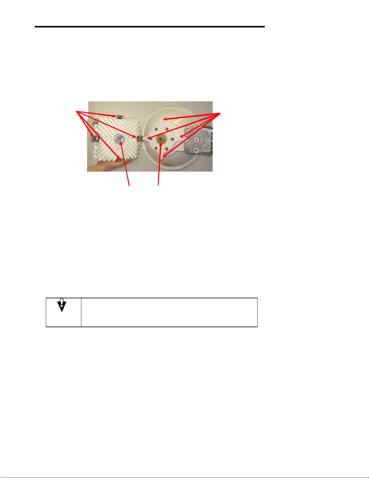
Four mounting
Four mounting
7.0 Antenna Mounting and Tower Specifications
The Horizon Compact unit clip mounts onto a range of antennas, providing a variety of gain and range
options. The same mounting system is used for all s izes of antenna.
The Horizon Compact has four, integral, spring loaded, mounting clips. The antennas are provided with
four mounting lugs, onto which the mounting clips attach. The antenna port and the waveguide adaptor of
the Horizon Compact, push fit tog ether before the clips are set, and are weather-sealed with a lubricated
‘O’ ring located on the outside surface of the antenna port (lubricate with provided lubricant before
assembling).
clips
Waveguide adapter
Antenna port
Figure 7-1 Horizon Compact showing clip mount features
lugs
7.1 Polarity
Horizon Compact units that operate on licensed radio bands use a diplexer system to simultaneously
handle transmitted and received signals to/from the antenna. In this case, both transmit and receive
antenna elements must have the same polarity.
For unlicensed radio band units, an orthogonal mode transducer (OMT) is used to allow the radio to
simultaneously transmit on one polarity and receive on the opposite polarity.
7.1.1 Licensed Radio Bands
Both Horizon Compact units must be mounted on the pole/tower oriented for the same polarization. i.e.
both vertical polarization, or both horizontal polarization.
Caution
Cross-polarized radios or antennas result in the signal strength being 20 30 dB below expected RSL levels! Ensure both radios have the same
orientation (vertical or horizontal).
Horizon Compact Release 1. 01.01 Wireless Ethernet Product User Manual – Volume 1
Page 40
DragonWave Inc.
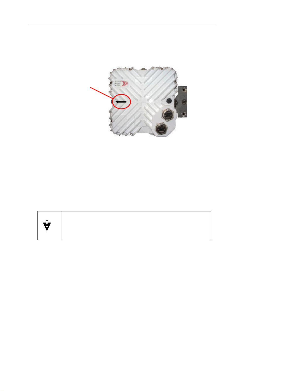
Polarity Marker
30
The radio frequency polarity is indicated by an arrow molded into the Horizon Compact housing. Attach
the Horizon Compact to the antenna so that the arrow points either vertically or horizontally, as required,
when the assembly is attached to the mounting post or tower. With the arrow horizontal (pointing to the
left) – horizontal polarity; with the arrow vertical (pointing upwards) – vertical polarity. For licensed
frequencies, the required radio polarity is defined in your licensing documentation.
This Horizon unit
is shown mounted
for horizontal
polarity (arrow
horizontal)
Figure 7-2 Horizon Compact polarity marker
7.1.2 Unlicensed Radio Bands (UL24)
For unlicensed radio bands, regulatory bodies require that both radios in a link have to be crosspolarized. This means that the antenna polarity of the transmitter at one end of the link is vertical and the
transmitter polarity at the other end it is horizontal.
The radio at one end of the link transmits vertically polarized and receives horizontally polarized, while the
other end transmits horizontally polarized and receives vertically polarized.
Caution
For 24 GHz Unlicensed Band, radios MUST be cross-polarized
i.e. Vertically polarized at one end and horizontally polarized at the other.
It does not matter at which end either radio is installed.
The radio frequency polarity is indicated by an arrow molded into the Horizon Compact housing. Attach
the Horizon Compact to the antenna so that the arrow points either vertically or horizontally, as required,
when the assembly is attached to the mounting post or tower. With the arrow horizontal (pointing to the
left) – horizontal polarity; with the arrow vertical (pointing upwards) – vertical polarity. For unlicensed
frequencies, one end of the link has to be vertically polarized and the other horizontally polarized (crosspolarized). It does not matter which end of the link has a specific polarization.
Horizon Compact Release 1. 01.01 Wireless Ethernet Product User Manual – Volume 1
Page 41
Installation Requirements
Roof
Roof
2.5 m
up
to and
Roof
>
30 cm 30 cm
7.1.2.1 UL24 Antenna Information
This device has been designed to operate with the antennas listed below, and having a maximum gain of
43.7 dBi. Antennas not included in this list or having a gain greater than 43.7dBi are strictly prohibited for
use with this device. This device has integrated an tennas.
24UL Antenna Data
1 foot Andrews VHLP1 -26DW 36.2dBi
2 foot Andrews VHLP2-26DW 40.8dBi
2.5 foot Andrews VHLP2.5-26DW 43.7dBi
31
7.2 Antenna Location
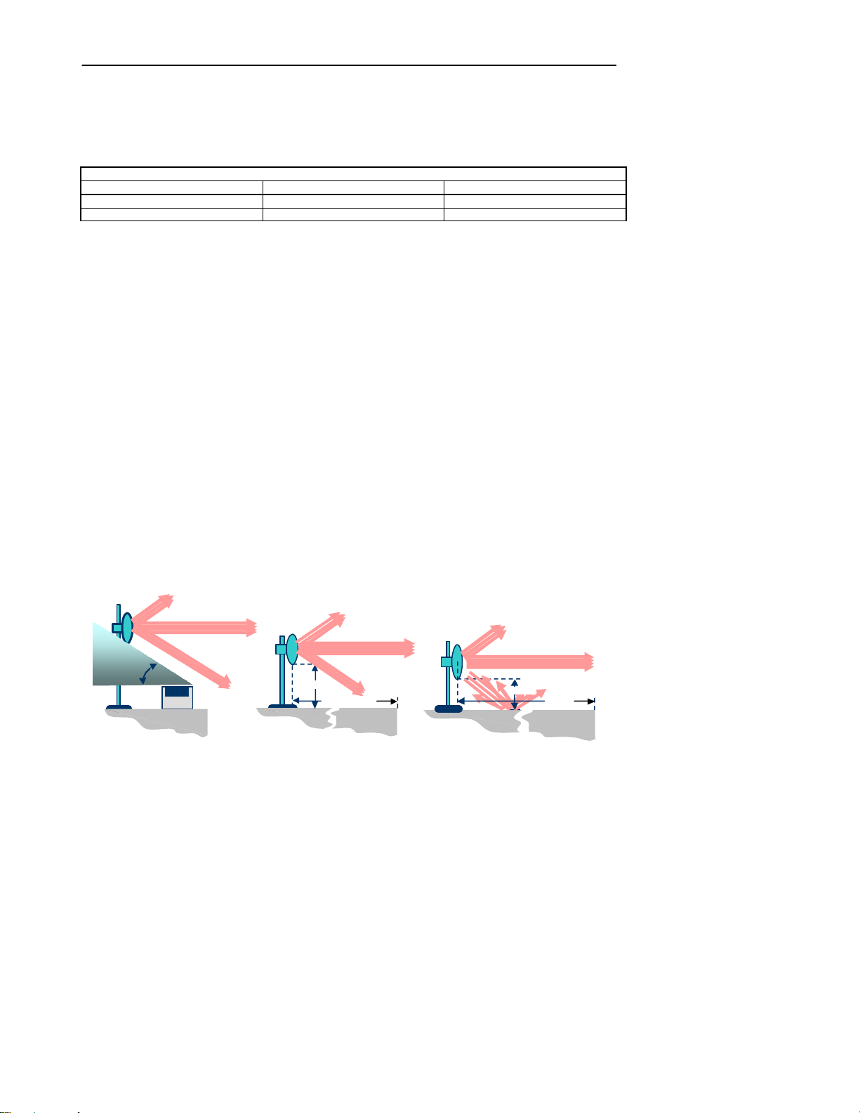
For both licensed and unlicensed systems, antenna location, relative to nearby obstacles, is an important
factor to consider when planning an installation. For systems mounted on buildings, roof edges and
parapets, the roof surface itself, air conditioning plant, other antenna systems, walls and overhead objects
are all considered potential obstacles. On tower mounted systems you must consider the proximity of
other antenna systems and mounting hardware.
Near field effects, resulting from a number of minor radiation lobes normally found around antenna
systems, can reflect off nearby objects and interfere w ith the normal reception of the radio. Reflected
waves can also change their polarity. This is especially important for unlicensed systems.
Consider an unlicensed installation that transmits with vertical polarity and receives with horizontal
polarity. If the near field vertically polarized transmitted signal reflects off an obstacle located too close to
the antenna system, then the reflected signal changes its polarity to horizontal, which is the same polarity
as the receiver. This causes the receiver to “swallow” the transmitted signal, resulting in receiver
“swamping”, excessive noise and the inability to receive the signal from the far end of the link. Ensuring
that obstacles and objects are not too close to the antenna system will avoid this problem.
As a “rule of thumb”, for both licensed and unlicensed installations, ensure that you maintain
an angle of 45 degrees, or greater, between the far side of the highest part of an obstacle and
the underside of the antenna.
Figure 7-3 illustrates this approach. Also, remember to apply this rule in all directions around the antenna,
above, below and to each side. An exception to this rule can be applied when the antenna is positioned
12.5 m (40 ft) or more from the edge of a roof clear of obstacles (a roof edge is considered an obstacle).
In this case the antenna need not be higher than 2.5 m (8 ft) above the roof surface. For more details on
antenna placement for unlicensed systems refer to Volume 2 of this manual.
Figure 7-3 Recommended Antenna Placement
greater than
Horizon Compact Release 1. 01.01 Wireless Ethernet Product User Manual – Volume 1
Page 42

DragonWave Inc.
32
7.3 Pole and Tower Specifications
It is important that mounting posts or towers used meet the DragonWave specifications for rigidity to
minimize the effects of twist and sway on the alignment of the link. Note that the maximum twist and sway
angle allowable is equal to half of the antenna beam width.
Table 7-1
Twist and Sway Specifications – Selected Frequencies
Frequency Antenna
18 GHz
23 GHz
Table 7-2
Mounting pole specifications
Antenna
Diameter
30 cm/12” 7.5 cm/3 “ 90 cm/ 36”
30 cm/12” 10 cm/4” 120 cm/48”
60 cm/24” 7.5 cm/3” 75 cm/30”
60 cm/24” 10 cm/4” 90 cm/36”
75 cm/30” 10 cm/4” 75 cm/30”
90 cm/36” 10 cm/4” (tower mount recommended)
120 cm/48” 10 cm/4” (tower mount recommended)
180 cm/72” 11.5 cm/4.5” (tower mount recommended)
Twist and sway caused by wind or human activity can cause a link to fail. Using poles with specifications
shown in Table 7-2 will result in a stable mounting system. Systems with antenna sizes of 90 cm/36” in
diameter and greater, are recommended to be mounted on towers.
Diameter
30 cm/12” 3 +/- 1.5
60 cm/24” 2 +/-1
90 cm/36” 1.3 +/- 0.65
120 cm/48” 1 +/- 0.5
30 cm/12” 2.7 +/- 1.35
60 cm/24” 1.7 +/- 0.85
90 cm/36” 1.1 +/- 0.55
120 cm/48” 0.8 +/- 0.4
Steel Pipe
Nominal Outside Diameter
3 dB Beamwidth
(degrees)
Max. Distance Above Last Rigid
Maximum Twist and Sway
(degrees)
Attachment Point
Horizon Compact Release 1. 01.01 Wireless Ethernet Product User Manual – Volume 1
Page 43

Installation Requirements
33
Horizon Compact Release 1. 01.01 Wireless Ethernet Product User Manual – Volume 1
Page 44
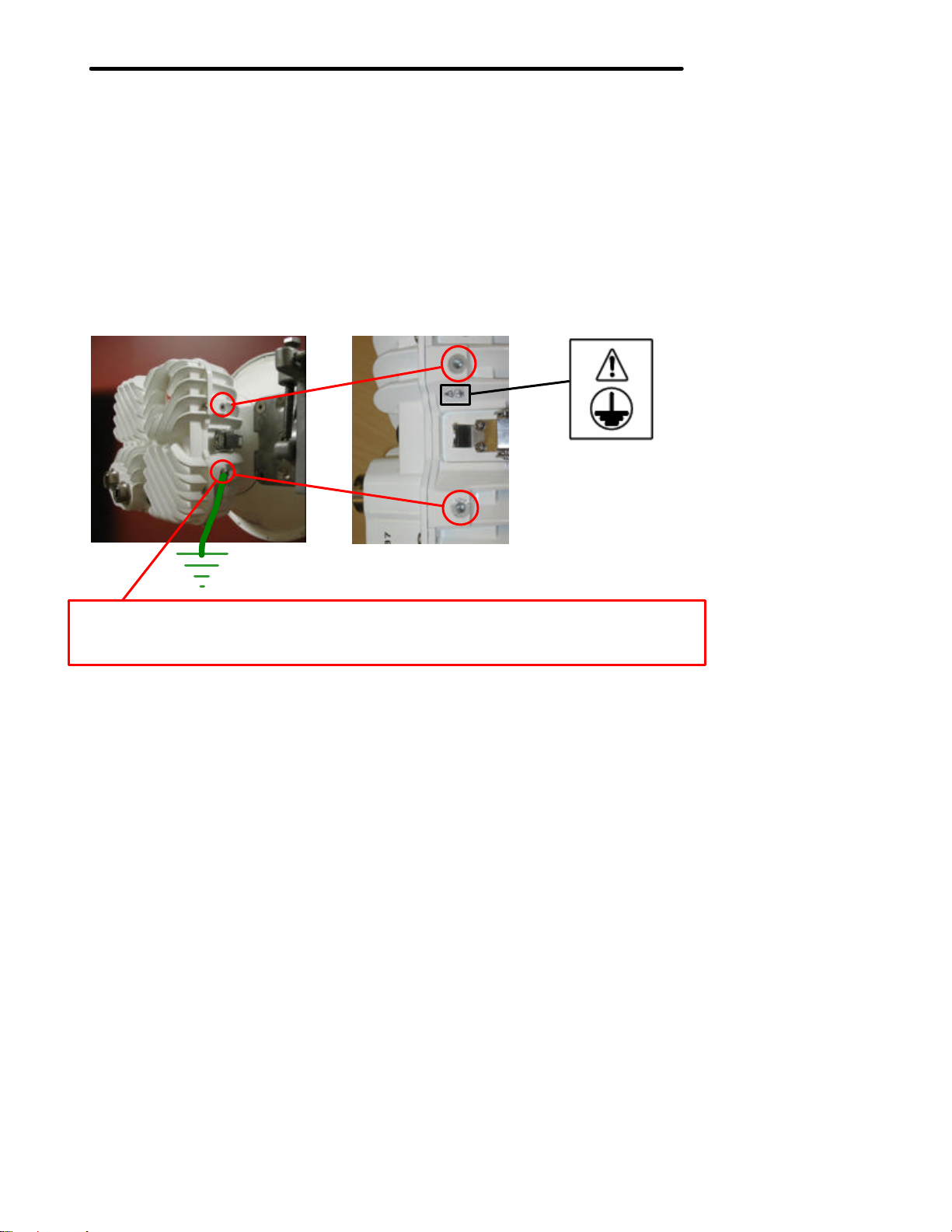
Grounding
8.0 Grounding, Power and Surge Arrestors
The Horizon unit must be grounded using a minimum of 6 AWG copper wire attached to any of the eight
ground points available on the Horizon case, as shown in Figure 8-1.
Surge arrestors and lightning protection is built into the Horizon unit.
The Ethernet and PonE cables must be properly protected at the end of their run as they enter the
building. Before Ethernet cable s enter buildings, voltages shall be clamped down to SELV by approved
type primary protectors.
For the copper interface option, proper use of the Horizon PonE unit provides lightning and surge
protection for the connected network. The PonE unit shall be installed according to local Electrica l Safety
Codes.
For the optical interface, proper use of the Transtector unit protects the optional management Ethernet
connection (if used) and the power supply.
Use 6 AWG or larger copper wire to connect from Horizon case grounding point to ground.
There are two grounding points on each of the four sides of the Horizon case.
Figure 8-1 Horizon Compact case grounding point
Horizon Compact Release 1. 01.01 Wireless Ethernet Product User Manual – Volume 1
Page 45
Grounding, Power and Surge Arrestors
35
8.1 Power on Ethernet (PonE)
The copper interface variant of Horizon operates on -48 VDC and employs a proprietary Power on
Ethernet solution. The Horizon Power on Ethernet surge arrestor unit provides integration of -48 VDC
and the two straight through Ethernet cables.
Note: The Horizon PonE implementation is proprietary and does not follow IEEE standards.
The surge arrestor uses RJ-45 connectors for the Ethernet cables and screw -terminals for the -48 VDC
power connections. Dual -48 VDC power connectors are provided, allowing for the connection of
redundant power supplies.
The surge arrestor unit contains protection against cable transients and power surges caused by lightning
or other sources. The surge arrestor is installed at the opposite end of the Cat5E/ PonE cables to that of
the Horizon unit and protects the network.
To ensure adequate lightning protection, the PonE surge arrestor unit must be properly grounded.
CAUTION
Serious damage to network switches or route rs can occur if
the network is plugged into the connectors marked “TO
HORIZON UNPROTECTED”. Power is fed to the Horizon unit
along the same wires that carry Ethernet traffic to the
Horizon unit. Do not, under any circumstances, plug cables
connected to the network into the RJ-45 connectors marked
“TO HORIZON UNPROTECTED”.
CAUTION
Only use straight through Ethernet cables to connect the
PonE adapter to the Horizon Compact. Using cross-over
cables will result in damage to the Horizon Compact unit.
CAUTION
Connect the Cat5E cables to the Horizon Compact BEFORE
applying power to the PonE surge arrestor unit.
Horizon consumes a nominal 20 Watts (standard power), or 40 Watts (high power variant) from the -48
VDC supply. All eight of the wires in the Ethernet cable are used to carry power to the Horizon Compact
unit. The Power on Ethernet surge arrestor unit is rated at 2 amps.
Horizon Compact Release 1. 01.01 Wireless Ethernet Product User Manual – Volume 1
Page 46
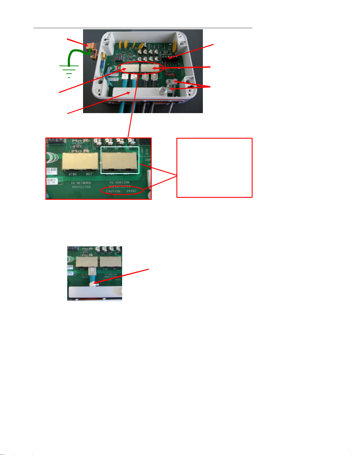
DragonWave Inc.
Redundant power
Ethernet cable
To network
(protected)
To Horizon Comp
act
CAUTION
Power cable
36
Grounding point
clamp
CONNECT ONLY
TO HORIZON
CONNECT TO
NETWORK
terminals (-48 VDC)
(Power on Ethernet)
clamps
DO NOT
Figure 8-2 Surge arrestor and power integrator
Two different sized cable clamps are provided for the power cable. Select the one that best suits the size
of cable being used.
The Ethernet cables are secured with a “bar” type clamp which is locked down using a single screw.
Additional cable security can be added by applying cable clips to the cables, as close to the clamp bar as
possible, as shown in Figure 8-3.
Cable clip
Figure 8-3 Ethernet cable clip
Horizon Compact Release 1. 01.01 Wireless Ethernet Product User Manual – Volume 1
Page 47

Grounding, Power and Surge Arrestors
37
This page left blank intentionally
Horizon Compact Release 1. 01.01 Wireless Ethernet Product User Manual – Volume 1
Page 48
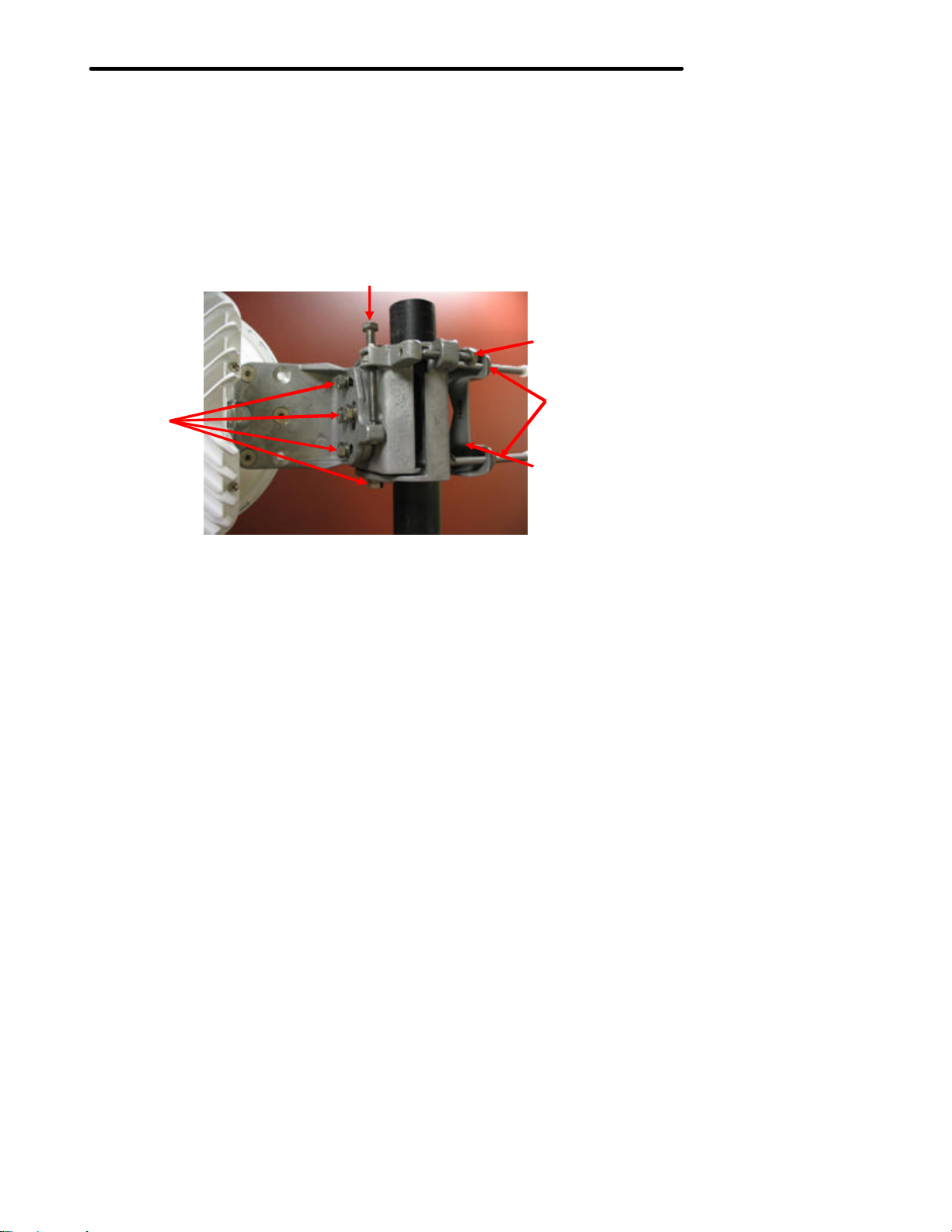
Lock nuts
9.0 Preparing for Alignment
The Horizon Compact and antenna assembly is attached to the mounting post, or tower, with a
specialized mounting bracket that allows fine orientation adjustment of the Horizon/antenna assembly.
The same mounting bracket is used for all ante nna sizes.
Visual alignment is achieved by rotating the assembly on the post, or tower, and positioning the assembly
so that the antenna is visually aligned with the target system before tightening the mounting bracket
clamp. Final alignment is achieved us ing the azimuth and elevation adjustment bolts. Once alignment is
achieved, the adjustment mechanisms are locked in place with lock nuts.
Figure 9-1 Mounting bracket with fine adjustment bolts
Final alignment is achieved by monitoring the received signal level (RSL) values as the system is
adjusted for azimuth and elevation. The BNC Field Strength Monitor connection is used in conjunction
with a voltmeter for RSL monitoring. See Section 9.1. Adjustments are made until the RSL value is at a
maximum, which should be within ± 3 dB of the expected value (link budget figure).
Elevation adjustment
Azimuth adjustment
Mounting clamp nuts
Mounting clamp
Horizon Compact Release 1. 01.01 Wireless Ethernet Product User Manual – Volume 1
Page 49
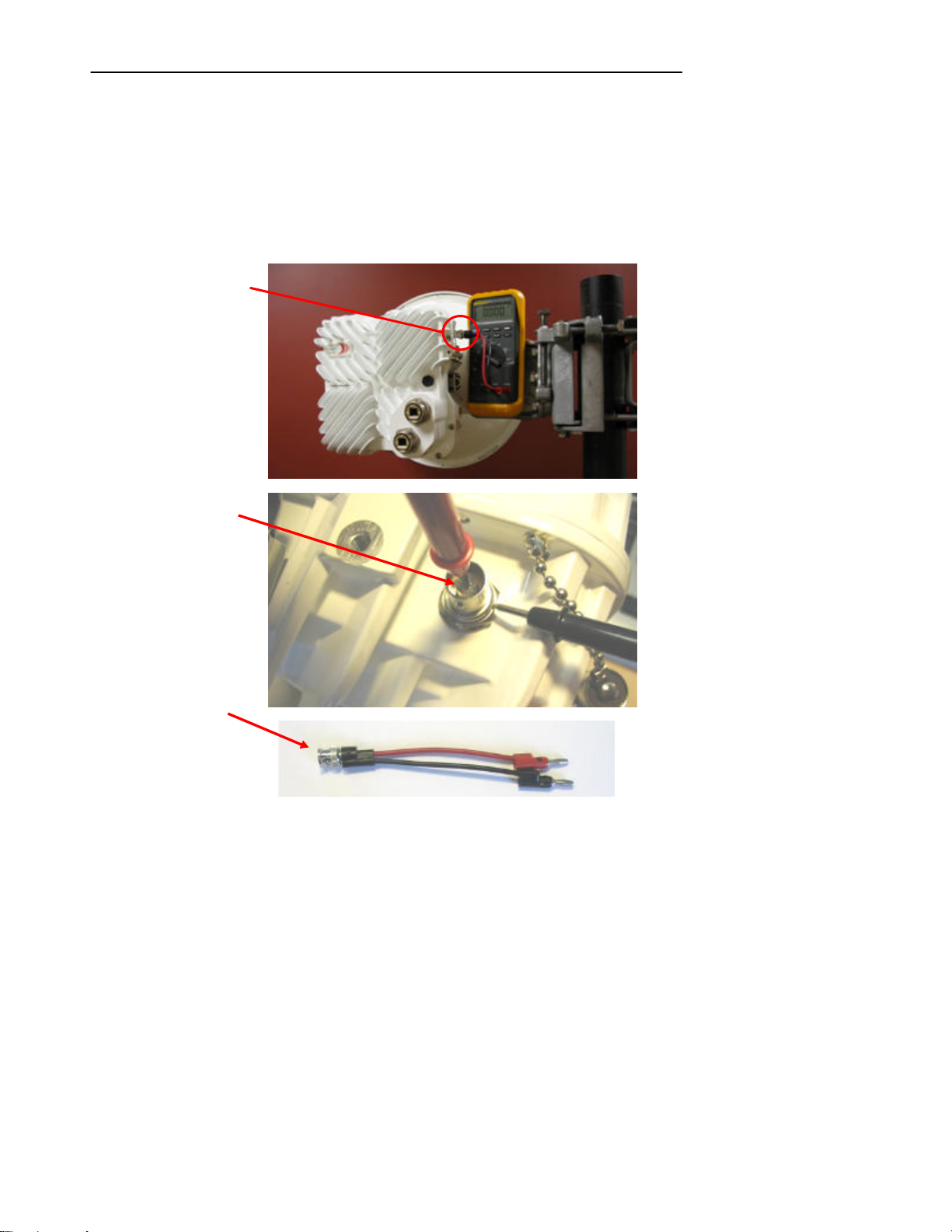
Preparing for Alignment
BNC field strength
Voltmeter probes
BNC to banana
39
9.1 Received Signal Level (RSL) Measurements
To accurately align the Horizon Compact to its far end peer, you need to monitor the received signal level
(RSL). There are two recommended methods for monitoring RSL. These are:
1. Use the CLI command set alignment on to activate the alignment feature at the BNC
connector located on the side of the unit. Connect a voltmeter to the BNC connector.
The voltage at this connector is linearly related to RSL and is 1 mV per dB e.g. -45 mV
= -45 dB. Note that the centre connection on the BNC connector is positive, so to read
negative values (to correlate with the negative RSL values) connect the negative pole
of the voltmeter to the centre connection.
Figure 9-2 Voltmeter connections to BNC field strength monitoring connector
connector
connected to BNC
connector
jacks cables are
available from your
voltmeter dealer,
or can be
constructed by the
user.
2. Alternatively, readings can be made remotely via the Web interface, using the Tools –
Link Alignment menu option. An operator would then have to continually relay RSL
readings, via a radio or cell telephone, to the rigger adjusting the positioning of the
system.
Horizon Compact Release 1. 01.01 Wireless Ethernet Product User Manual – Volume 1
Page 50

DragonWave Inc.
40
9.2 Three Important Factors
When you prepare to align the radio antennas , you must consider three important factors:
1. the radiation patterns of dish antennas (main lobe and side lobes)
2. the need for a Clear Line of Sight (LoS)
3. the sensitivity of the alignment adjustment
9.2.1 Antenna Radiation Patterns
The dish antennas used for the DragonWave Horizon Compact have high gains and very narrow beam
widths, making antenna alignment a critical element of a successful installation. In addition to the main
antenna beam, or lobe, there are often side lobes. Care must be taken to ensure that alignment is made
to the main lobe and not onto a side lobe. If you align onto a side lobe, the RSL will be at least 20dB less
than expected.
Table 9-1 Antenna Gains and Beam Widths – Selected Frequencies
Size
30 cm/12” 3.0 degrees 34 2.7 degrees 35.1
60 cm/24” 2.0 degrees 38.6 1.7 degrees 40.2
90 cm/36" 1.3 degrees 42.0 1.1 degrees 43.7
120 cm/ 48” 1.0 degrees 44.5 0.8 degrees 46.2
18 GHz Horizon 23 GHz Horizon Antenna
Beamwidth of
main lobe
(degrees, 3 dB)
Gain
dBi
Beamwidth of
main lobe
(degrees, 3 dB)
Gain
dBi
9.2.2 Clear Line of Sight (LoS)
The DragonWave Horizon Compact requires a clear LoS between the units at each end of the link. You
must be able to see an unobstructed view of the antennas from each end. Avoid obstacles that are close
to the LoS mid-way between antennas, but not blocking it, as this can have a negative impact on signal
quality (Fresnel zone clearance). Also, ensure that antennas are mounted with adequate clearance from
roof tops, roof edges, walls and other obstacles (e.g. air conditioning plant) to avoid problematic near field
effects.
9.2.3 Alignment Adjustment Sensitivity
When aiming the antenna it cannot be over emphasized that you must rotate the adjustment nut(s) 1/10th
of a turn at a time between taking RSL readings (allow time for the RSL reading to update). One full turn
of the adjustment mechanism can move the antenna through 1.6 degrees azimuth or 2.2 degrees of
elevation. Table 9-1 shows that the beam width of the typical antenna is often less than the amount of
movement available with one full turn of the aiming adjustment.
Horizon Compact Release 1. 01.01 Wireless Ethernet Product User Manual – Volume 1
Page 51

Preparing for Alignment
41
This page left blank intentionally
Horizon Compact Release 1. 01.01 Wireless Ethernet Product User Manual – Volume 1
Page 52

10.0 Aligning the Antennas
Follow the steps of the alignment procedure shown below . Note: ensure that the CLI command set
alignment on has been entered at both ends of the link if you are using the BNC connector to measure
field strength.
At the first end:
1. Loosen the pan mechanism lock nuts
2. Pan or move the antenna horizontally across the entire range of adjustment to identify
the main lobe and the side lobes. The main lobe is approximately 2 degrees in width
(depends on frequency and antenna size). The two major side lobes are approximately 5
degrees apart. Adjust the antenna to the main lobe (approximately).
3. Tighten the pan mechanism lock nuts and loosen the tilt mechanism lock nuts.
4. Tilt or move the antenna vertically until you receive the strongest RSL reading.
5. Tighten the tilt mechanism lock nuts and loosen the pan mechanism lock nuts.
6. Pan or move the antenna horizontally to locate each of the lobes. Record the RSL
values of each. Select the strongest RSL recorded and readjust the antenna to this
strongest RSL reading.
7. Re-tighten the pan/tilt mechanism lock nuts to lock the antenna in place.
At the other end:
8. Repeat steps 1 through 7
Return to the first end:
9. Loosen the pan mechanism lock nuts.
10. Pan or move the antenna horizontally across the entire range of adjustment to identify
the main lobe and the two major side lobes. Adjust the antenna to the main lobe
(approximately).
11. Tighten the pan mechanism lock nuts and loosen the tilt mechanism lock nuts.
12. Tilt or move the antenna vertically until you receive the strongest RSL reading.
13. Tighten the tilt mechanism lock nuts and loosen the pan mechanism lock nuts.
14. Pan or move the antenna horizontally and locate the strongest RSL reading.
15. Re-tighten the pan/tilt mechanism lock nuts to lock the antenna in place.
16. Repeat steps 1 through 15 as necessary to obtain maximum RSL reading.
Notes:
The RSL level should be within ±3 dB of predicted levels. Factors that contribute to low RSL levels are:
• incorrect antenna alignment - aligned to a side lobe and not main lobe
• improper polarization of antennas – one end horizontal and the other vertical
• path issues - obstructions such as trees, hills, or buildings within the beamwidth
• path clearance issues such as diffraction, partial obstruction, Fresnel zone issues
Horizon Compact Release 1. 01.01 Wireless Ethernet Product User Manual – Volume 1
Page 53

Preparing for Alignment
43
10.1 Signs of a Healthy Link
You can be confident that a link is properly aligned and free of problems if the following readings are
obtained during a Telnet or Web interface session with each end of the link :
• No alarms – use the CLI command get alarms and press Enter to return a list of current
alarms – should be none that cannot be explained by network status
• Received signal level (RSL) within ±3 dB of link budget figure in clear weather. Use the
CLI command get modem statistics and press Enter to obtain the RSL reading. The
Unchannelized power reading should be within 6 dB of the RSL reading. If the
Unchannelized power drops below -75 dB, then it is likely that there is no signal being
presented at the radio portion of Horizon Compact. Check alarms.
• Eb/No of 19 dB or higher – use the CLI command get modem statistics and press Enter
to display the Eb/No value
• Signal to Noise Ratio (SNR) of 24 dB or higher – use the CLI command get modem
statistics and press Enter to display the SNR value
• Equalizer Stress typically between 20 and 30, but never more than 150 - use the CLI
command get modem statistics and press Enter to display the Equalizer stress value
• Modem Block Error Rate 0.00e+00 – use the CLI command get traffic statistics and
press Enter to display the Modem Block Error Rate. Modem block errors are an
indication of loss of data frames. Note that there are residual modem block errors as a
result of the alignment process.
• Transmit power typically set at the maximum for the radio band used – use the CLI
command get transmit power and press Enter to return the configured transmit power
• All sections operational – use the CLI command get health and press Enter to return the
health status of all three sections of the system
The readings obtained using the CLI commands during a Telnet session can also be retrieved using the
Web interface. All items listed here are available on the left- hand pane of the Web interface and appear
on each Horizon web page.
Horizon Compact Release 1. 01.01 Wireless Ethernet Product User Manual – Volume 1
Page 54

11.0 Advanced Configuration Features
DragonWave Horizon Compact has a number of optional advanced configuration features that may be
applied if desired. It is recommended that they only be applied once the Horizon Compact is satisfactorily
aligned and successfully carrying traffic. The following lists the features available:
• Radius Server User Authentication • Threshold Alarms
• VLAN Tagging • Rapid Link Shutdown (RLS)
• 802.1P Priority Tagging
• Horizon Throughput Speed • Adaptive Modulation
• Adaptive Transmit Power Control
(ATPC)
• Modem Authentication
Each feature is described in this manual, but detailed configuration information for each can be found in
the Horizon Product Manual Volume 2 - Advanced Features.
11.1 RADIUS Server User Authentication
The DragonWave Remote Authentication Dial In User Service (RADIUS) server option enables users to
be centrally authenticated before being allowed access to a Horizon Compact unit. This adds another
layer of security by removing user access control away from individual units and moving it to a central
server. However, all Horizon Compact units must have all approved users entered in the user
authentication list before the system will grant access at the appropriate user levels (admin, NOC, Super).
Up to five (5) RADIUS servers can be configured.
When one, or more, RADIUS server is configured, the username and password authentication system on
the Horizon Compact is bypassed, in favour of the RADIUS system. Access levels are still retained in the
local Horizon Compact memory, so once a user is verif ied by the RADIUS server the access level is
assigned by the Horizon Compact (provided that that user is a valid user on that unit). Any user that is
validated by the RADIUS server, but is not found in the Horizon Compact user authentication list, can
gain access to the unit but only at an admin user level.
If, on attempting to log in, a user does not receive a response from a configured RADIUS server, the user
will not be allowed to log in.
Only the Super User can issue any of the RADIUS “set” commands a nd view any of the security related
entries returned with “get” commands (passwords, shared key etc..)
• Simple Network Timing Protocol
(SNTP)
• Radio Redundancy
Horizon Compact Release 1. 01.01 Wireless Ethernet Product User Manual – Volume 1
Page 55

Advanced Configuration Features
45
11.2 Management VLAN Tagging
Note: The configuration of Horizon Compact VLAN tagging is only necessary if you wish to restrict
Horizon Compact management communications to a specific management VLAN.
The Horizon Compact system will pass user VLAN traffic transparently, independent of the Horizon
Compact VLAN settings. The VLAN settings are for Horizon Compact management purposes and do not
affect user data or traffic. VLAN Standard IEEE 802.1Q is supported for Horizon Compact VLAN tagging
and it accommodates up to 4096 VLANs within the “8100” VLAN range. Note that the Horizon Compact
system handles Ethernet frame sizes up to 9600 bytes.
There are three pa rameters associated with Horizon Compact VLAN tagging:
1. Enable or disable VLAN tagging (set VLAN tagging [on/off])
2. Identify the VLAN tag id to be used with Horizon Compact (set VLAN tag [tag id])
3. Determine whether to allow Horizon Compact to match the VLAN settings in response to
incoming frames, or whether to restrict responses to those incoming frames containing
the programmed VLAN tag. There are two modes (set network protocol strict [off/on])
which are commonly known as “friendly” and “strict” mode.
i. “Friendly” mode. In this mode, Horizon Compact matches the VLAN format of
the incoming frame. If an incoming frame contains a VLAN tag, then Horizon
Compact responds with a VLAN tag matching the incoming frame. If the
incoming frame does not contain a VLAN tag then Horizon Compact does not
insert a VLAN tag in the response. Frames generated by Horizon Compact
(e.g. SNMP traps) will contain the programmed VLAN tag.
ii. “Strict” mode. Horizon Compact will only respond to frames containing the
programmed VLAN tag. All other frames will be ignored. Frames generated by
Horizon Compact (e.g. SNMP traps) will always contain the programmed VLAN
tag.
11.3 802.1P Priority Queuing Implementation in Horizon Compact
QoS implementation is best done on the ingress and egress portions of the transport network. As such,
QoS should be implemented on the Ethernet switches. Once that implementation is in place, the Horizon
Compact can be configured for QoS, should the potential for congestion exist. Enabling CoS/QoS
(802.1P) on Horizon Compact ensures that the high priority traffic is delivered at the expense of lower
priority traffic.
Horizon Compact supports the eight Class es of Service (CoS) levels (0-7) defined within 802.1P. There
are four CoS Queues within Horizon Compact, numbered 1 to 4. Any of the eight CoS levels can be
assigned to any of the four Horizon Compact CoS Queues. Horizon can also be configured to use the
priority bits found in the DSCP field of IP headers. Any frames not having an IP header can be classified
based on the default class of service value (set cos default value [0 though 7]).
There are three additional Horizon Compact settings that can be used to customize the data flow to
match network requirements:
1. CoS Committed Information Rate (CIR), which de termines the guaranteed bandwidth allocated to
a particular Queue.
2. CoS Committed Burst Size, which determines the amount of burst data the Queue can manage.
3. Expedite Queuing (see Section 11.3.3), which allows a Queue to be set as a priority Queue
whereby it delivers its data at the expense of other non -Expedite Queues.
Horizon Compact Release 1. 01.01 Wireless Ethernet Product User Manual – Volume 1
Page 56

DragonWave Inc.
46
11.3.1 Operation with 802.1P Priority Queuing Disabled
If 802.1P filtering is disabled in the Horizon Compact system, all incoming frames are treated equally and
are forwarded on a first-come first-served basis. The system operates in a FIFO (First In First Out) basis.
If the Pause Frames feature (see Section 11.4) is enabled, pause frames will be sent to the connected
switch when the input buffer is close to being full (internally set threshold). This allows time for the queue
to empty prior to more frames being received and thus avoids congestion.
11.3.2 Operation with 802.1P Priority Queuing Enabled
If 802.1P filtering is enabled in the Horizon Compact system, the scheduling mechanism can be
described as follows:
1. Select the highest priority queue which has a frame in it
2. Send that frame
If COS CIRs are set for the queues, then the scheduling mechanism can be described as follows:
1. Select the highest priority queue which has a frame in it, and hasn’t used up its CIR budget
2. Send that frame
The operation of the Scheduler is affected by both the user-configurable CIR and CoS Queue PBS
settings.
If the Pause Frames feature (see Section 11.4) is enabled, pause frames will be sent to the connected
switch when the input buffer is close to being full (internally set threshold).
The Horizon Compact system also allows any frames without a VLAN tag to be allocated an 802.1P CoS
level (“set untagged frame priority”). If the “set untagged frame priority” is not configured, then all
untagged frames will be forwarded through Queue 1.
Horizon Compact is also able to manage Q- in-Q or Super VLAN traffic. The system can be configured to
use either an encapsulated frame’s priority tag or the encapsulating frame’s priority tag, in determining
priority handling.
11.3.3 Expedite Queues
Expedite Queuing is a mechanism that allows one or more of the four Queues to transmit its data as
priority traffic, at the expense of the remaining Queues. When Expedite Queue is enabled, then as long
as there is data in the Expedite Queue, or Queues, that data will be transmitted first . This allows time
critical or error-sensitive traffic to have priority data delivery.
As network services increase, the need for multiple Expedite Queues becomes evident. A network
administrator may require three Expedite Queues and decide to send all network routing protocols
through the highest Expedite Queue; send IP Voice through the next highest Expedite Queue; send Video
over IP through the next highest Expedite Queue and send all other traffic to the remaining Queue, which
is not configured as an Expedite Queue. To do this, the administrator would configure Queues 4, 3 and 2
as Expedite Queues and configure Queue 1 as a standard Queue with a particular CIR. Configuring the
CIR for a particular queue to 100% enables the expedite function for that queue.
11.3.4 Management Traffic
Slow Ethernet services and multicast frames are handled by a special Queue inside the Horizon
Compact. The Queue is not user-accessible. It works similar to an Expedite Queue in that it ensures
management traffic is passed through in an “expedited” fashion. It does not affect, nor is related to the 4
Queues within Horizon Compact. This Queue does not impact the operation of the 4 user-configurable
802.1P Queues.
Horizon Compact Release 1. 01.01 Wireless Ethernet Product User Manual – Volume 1
Page 57
Advanced Configuration Features
Average
Threshold
47
Frames destined for the 01-80-C2-00-00-xx MAC addresses are sent to the internal Queue. Examples:
STP, RSTP, MSTP LACP, Pause Frames, GARP (GMRP,GVRP), bridge broadcasts, OAM, LLDP, Port
based authentication are all sent to the internal Queue and are transmitted in an expedited fashion.
Other frames that the user determines must be treated in an expedited fashion, such as “keep-alive”
frames and MRP frames, must be assigned a CoS within the switch, then assigned to the appropriate
Queue within Horizon Compact.
11.4 Pause Frames
Pause frames are generated by the weaker (slower) link when its forward pipe gets full. Pause frames
inform the upstream device to “pause and stop sending traffic for a period of 5 msec”. When the Pause
Frame feature is enabled, Horizon Compact generates pause frames to the Ethernet switch when the
Horizon Compact receiving buffer hits the internally set threshold. The receiving buffer threshold is close
to 100 msec at GigE rate. At data rates lower than GigE, the data buffer will accommodate a lesser
amount of data. The Pause Frame feature can be used when CoS/QoS is enabled or disabled.
11.5 Horizon Compact Throughput Speed
When you purchase a Horizon Compact system you receive a unit capable of giving a throughput speed
of up to 400 Mbps. However, the actual throughput speed achievable for any given system depends on
the specific throughput speed key that you purchased with the system
You can upgrade your system to a higher licensed throughput speed (up to 400 Mbps) by purchasing an
upgrade key and reprogramming your system. Any upgraded system can be reconfigured to a lower
throughput speed as required, without losing the ability to return to the upgraded speed.
You may also downgrade a system to a lower licensed speed. A downgraded system may warrant a
refund of licensing fees. A downgraded system cannot be returned to its former higher licensed speed
without purchasing another licensed upgrade key.
11.5.1 Maximum Throughput Speed
The maximum throughput speed is determined by the Horizon Compact throughput speed key you
purchase, however, it is important to note that this is also determined by the Channel bandwidth
associated with the configured radio band, and the modulation scheme used. The channel bandwidth is a
function of the radio band, and the modulation scheme is automatically selected depending on the
desired maximum throughput. Configuring the Radio Band and System Mode of the system determines
the maximum throughput and hence determines the modulation scheme applied.
Note: if you set a System mode of hc50_110_16QAM, the 110 figure indicates the maximum throughput
speed capability of that mode. However, if your licensed throughput speed key purchased from
DragonWave is less than this figure, your system throughput will be limited to the purchased licensed
throughput speed. Table 11-1 shows the modulation schemes that are selected for various Operating
Modes when 23 GHz radio band with 50 MHz channel spacing is configured.
Table 11-1 Bandwidth Operating Mode and Modulation Scheme (50 MHz Channel bandwidth)
Horizon Compact Release 1. 01.01 Wireless Ethernet Product User Manual – Volume 1
Operating
Mode
HC50_67 QPSK 67 17/27 -81 -18
HC50_110 16QAM 110 14.5/24.5 -77/ -75 -20.5
HC50_171 32QAM 172 14/24 -72/ -70 -21
HC50_215 64QAM 216 12.5/22.5 -68 -22.5
HC50_271 128QAM 272 11/21 -62 -24
HC50_322 256QAM 323 11.5/21.5 -59 -24.5
HC50_371 256 QAM 372 9.5/NA -59 -25.5
HC50_364 256 QAM 364 ** NA/19.5 -59 -25.5
Modem Mode
Packet
Throughput
(Mbps)
Max Tx
Power
SP/HP
(dBm)
BER 10 -6
SP/HP
Saturation
(dBm)
BER 10-6
Page 58

DragonWave Inc.
48
Note: The average packet throughput is calculated using 64, 128, 256, 512, 1024, 1280, and 1518bytes
Ethernet frames.
** Throughput optimized to fit within required spectral mask limits .
11.6 Adaptive Transmit Power Control (ATPC)
Adaptive Transmit Power Control (ATPC) allows a Horizon Compact system to adjust its transmit power
to compensate for far end signal loss caused by changes in atmospheric conditions e.g. heavy rain.
ATPC maintains the RSL at -50 dB and adjusts the transmit power by up to 20dB as necessary in order to
maintain -50 dB during fade conditions.
RSL threshold levels that trigger power changes, the maximum power change allowed, and a hysteresis
factor are preset at values which optimize the operation of the Horizon Compact system. A fade factor of
5dB/second can be handled.
The Horizon Compact system is able to discriminate between RSL levels that ar e reduced as a result of
interference and those as a result of genuine path loss, so that ATPC is not invoked unnecessarily.
Some jurisdictions require the use of ATPC so that power levels are kept as low as possible when
wireless communication conditions are good. When ATPC is to be used, if it can be shown that the
maximum power of the system would be used only on infrequent occasions, some jurisdictions will allow a
lower power level to be used in the calculations that determine interference criteria. Th is offers some
advantage to the installation. This lower power is termed the “coordinated power”. The DragonWave
ATPC feature supports a coordinated power parameter.
ATPC is enabled or disabled by issuing the CLI command set atpc [on/off][coordinated power]
The current status of ATPC can be determined by using the CLI command get atpc status .
Note: If ATPC and Advanced Adaptive Modulation (AAM) are both enabled, when AAM is invoked i.e.
modulation scheme switched to a lower level, ATPC is automatically disabled until AAM restores the
original modulation scheme.
Horizon Compact Release 1. 01.01 Wireless Ethernet Product User Manual – Volume 1
Page 59

Advanced Configuration Features
49
11.7 Horizon Compact Authentication
This feature is only necessary if you wish to restrict communication from a Horizon Compact unit to a
specific peer or to a group of Horizon Compact units. Authenticat ion is generally used as a security
measure. It is not recommended to enable Authentication prior to alignment of the radios.
Authentication restricts a Horizon Compact unit from communicating with other Horizon Compact units
unless the other units match an authentication string. There are three types of authentication:
1. No Authentication
2. Unique Authentication
3. Group Authentication
A new Horizon Compact system in line with the signal cannot authenticate and receive data if another
Horizon Compact system is already authenticated. The system authenticates its peer(s) at an interval of
approximately five seconds.
The Horizon Compact node does not accept data from other manufacturers’ systems.
Horizon Compact Release 1. 01.01 Wireless Ethernet Product User Manual – Volume 1
Page 60

DragonWave Inc.
50
11.8 Threshold Alarms
Horizon Compact provides Threshold Alarms to assist in managing the performance of the system.
Threshold alarms are available for the following parameters:
With the exception of SNR, each Threshold Alarm has two associated parameters:
The combination of the value and the time limit is user defined. The proper combination of the two
parameters will prevent fal se alarms from occurring.
* For the SNR parameter, only the threshold level can be set, the time limit, or hysteresis, being a preset
value.
1. RSL (Receive Signal Level)
2. Bandwidth Utilization
3. Dropped Frames
4. Signal To Noise (SNR) *
1. Threshold value
2. A time limit over which the Threshold value must be exceeded before the alarm is
reported.
11.9 Rapid Link Shutdown
It is often desirable to signal or detect network link issues in the quickest manner possible. This is
especially true when running Layer 2 redundancy protocols, such as Spanning Tree and Metro Ring
protocols. Signalling to the network is done by shutting down the Ethernet data port(s) connecting the
Horizon Compact to the network. The Rapid Link Shutdown (RLS) feature provides this functionality.
Some situations that would result in Rapid Link Shutdown include:
• Link outage. Should a power failure or a complete loss of link occur then Ethernet ports at both
ends of the link can be shut down
• Far-end Ethernet connection problems. If the remote unit data Ethernet port is disconnected or
disabled, the near-end unit will also shutdown it’s Ethernet port
• Link quality problems. If the link quality (error rate) reaches user programmable thresholds the
Horizon Compact Ethernet ports can be shut down
• Horizon Compact configuration or hardware failure. If hard faults, such as a hardware failure,
interrupt the link, both Horizon Compact Ethernet ports can be shut down.
11.10 Configuring the Time Source (SNTP)
Date and time information can be entered into the system using CLI command set date time [dd/dd/yyyy
hh:mm:ss:ms] press Enter.
The date and time settings in Horizon Compact are not maintained if a power outage is experienced. To
ensure that set system date and time are always accurate, the system can poll known time sources and
update time information on an ongoing basis.
Up to five time sources can be configured, which can provide accurate time and date information to the
system. Simple Network Time Protocol (sntp) is used. Either an Internet time source or an NTP server on
your network may be used.
Five time sources are configured by default (see Table 11-2). Each time source is indexed 1 to 5. Indices
1 and 2 are from Industry Canada servers, 3 and 4 are from U.S. Navy servers and 5 is from a Swiss
server. Any other time sources can be configured. The timing information is polled every 60 minutes.
Horizon Compact Release 1. 01.01 Wireless Ethernet Product User Manual – Volume 1
Page 61

Table 11-2 Time Sources
Advanced Configuration Features
51
Index Stratum
1 2 199.212.17.15 Industry Canada
2 2 199.212.17.20 Industry Canada
3 1 192.5.41.40 U.S. Navy
4 1 192.5.41.209 U.S. Navy
5 2 129.132.2.21 Switzerland
Source
IP Address
Source
11.11 Automatic Adaptive Modulation (AAM)
The two principal modulation schemes used on the Horizon Compact system are QPSK and QAM. QPSK
(the lowest modulation scheme) is ideal for long distance, but has the lowest throughput capability.
Higher throughputs are achieved by using more complex modulation schemes e.g. 16-QAM, 32-QAM,
64-QAM, 128-QAM, 256-QAM. The higher numbers indicate a progressively more complex scheme and a
higher bandwidth (throughput) capability e.g. 256-QAM is more complex than 128-QAM and provides a
higher throughput. More complex modulation schemes are susceptible to noise and thus require a
stronger signal for the demodulator to accurately decode the data stream. Consequently, the more
complex the modulation scheme used, the shorter the distance limitation of the radio link.
If a system is using a given modulation scheme and weather conditions cause signal levels to deteriorate
below acceptable levels (risking a link failure), changing the modulation scheme to a less complex
scheme, will allow the link to remain functional, although the throughput will be low er, until weather
conditions improve. The modulation scheme can then be returned to the original scheme and the
throughput returned to normal levels.
The Horizon Compact system can be configured to automatically change modulation schemes if
environmental conditions deteriorate to the point where a wireless link may otherwise fail. This feature is
called Automatic Adaptive Modulation (AAM). Note that AAM cannot be invoked if RLS is enabled.
The current modulation scheme (determined by the configured system mode parameter) will switch to the
lowest modulation scheme available (a number of system modes, which includes the modulation scheme,
are available for any given radio band, see Section 6.2), if the Horizon Compact units detect errored, but
corrected, frames (caused by reduced RSL levels) . The original modulation scheme will be restored once
preset parameters indicate that conditions are suitable for returning to the original modulation scheme
(and return to the original bandwidth). The total outage time due to modulation downshift is
approximately 50 to 100 mS on average, with upshift down time at approximately 75 mS.
All radio bands available with the Horizon Compact support AAM.
Horizon Compact Release 1. 01.01 Wireless Ethernet Product User Manual – Volume 1
Page 62
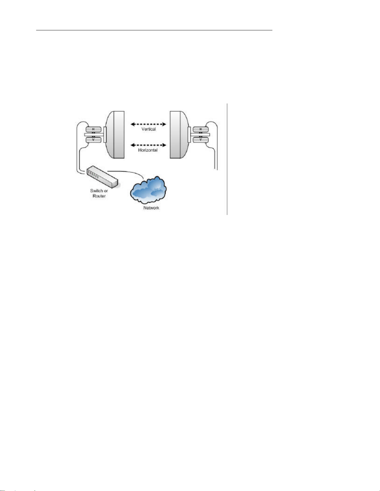
DragonWave Inc.
52
11.12 Horizon Compact Throughput Doubling
Horizon units are capable of transmitting up to 400 Mbps. For higher data rates, an Ethernet switch that
supports link aggregation is required. Horizon can be configured as 2 units, each with their own separate
antenna, or the Dual Polarity Radio Mount (DPRM) can also be used to mount two systems to a single
antenna (see Figure 3-3). The DPRM allows both systems to transmit/receive simultaneously, one with
horizontal polarization and the other with vertical polarization, supporting load sharing or throughput
doubling (up to 800 Mbps) (see Figure 11-1)
Figure 11-1 DPRM and Throughput Doubling
11.13 Horizon Redundancy
The Horizon system can be configured for redundancy using two physical options. One option allows for
two separate Horizon units, each with its own antenna, and connected to an Ethernet switch configured
with a re-routing protocol. The switch is responsible for re-routing the data to the redundant stand-by unit
when a failure occurs. This option is termed the “two wire” option.
The second option has two Horizon units mounted on a Power Switch Radio Mount (PSRM) with the data
feed from a single connection to a switch. Switching traffic to the redundant stand-by unit is determined
and performed by the Horizon Compact system and not the connected switch. This option is termed the
“single wire” option.
The configuration steps for each option are different (see Volume 2 for more details).
11.13.1 BNC Connector
The BNC connector on the side of the Horizon Compact serves a dual purpose. It can be configured as a
source for field strength measurements during antenna alignment, or configured to provide a redundancy
switch signal to a second Horizon Compact system mounted close by. For redundancy, the BNC
connectors on both units are interconnected with a coaxial cable. Note that for redundancy to work, you
must ensure that the field strength option for the BNC connector is turned off ( set alignment off).
When the Horizon system is configured for redundancy, a DC signal is presented at the BNC connector of
the unit normally carrying traffic . Since the BNC connectors on both units are interconnected, the DC
signal is passed to the stand-by unit. As long as the DC signal is present, then the stand-by radio is held
Horizon Compact Release 1. 01.01 Wireless Ethernet Product User Manual – Volume 1
Page 63
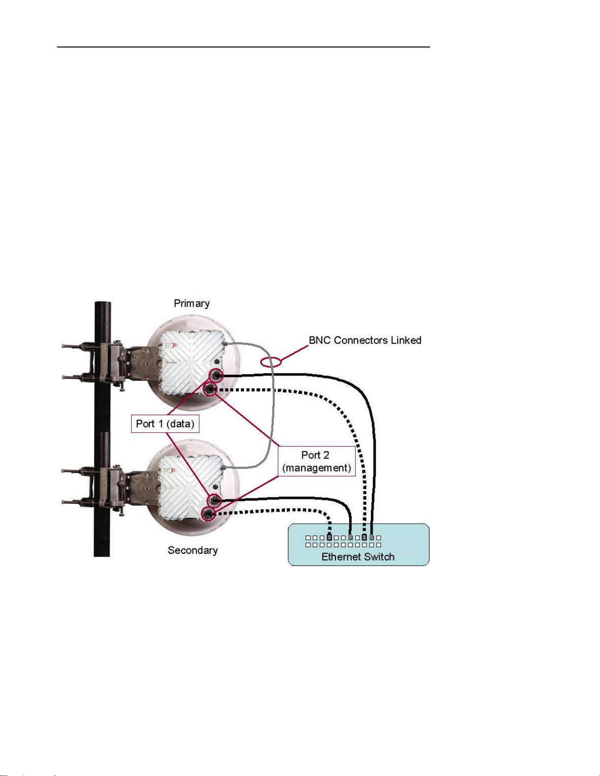
Advanced Configuration Features
in a hot stand -by state. When the DC signal is removed (as a result of the unit normally carrying traffic
failing), then the stand-by radio becomes active, and takes over the traffic. After a redundancy switch,
once the first system is able to return to carrying traffic, a manual switch is required, via a CLI command,
to return the system to its original state.
53
11.13.2 Two Wire Option
The “two wire” option is so named because two separate data feeds are required; one to each Horizon
system. One Horizon system is configured as the primary and the other as the secondary. Note that the
terms “primary” and “secondary” relate solely to the internal functions of the units and has no relationship
to which radio is in stand-by or which is carrying traffic. Management has to be via Port 2, so each
Horizon will be configured for out-of-band management and have its Port 2 connected to the overlay
management network.
Data re- routing, between the Horizon systems, is dependant upon a connected Ethernet switch. Ethernet
switch settings are used to reroute the traffic from one Horizon unit to the other, when a failure occurs.
Protocols such as RSTP, LACP and routing protocols are able to determine that the Horizon units have
switched from active to stand-by units, or vice-versa, and will reroute the data traffic through the active
link.
Figure 11-2 Redundancy Connections – 2 wire option – copper interface
NOTE: For clarity, the PonE power adapter and surge arrestor have been omitted from the
diagram. Both the Port 1 and Port 2 Ethernet connections and the power feed via Port 1 must be
protected from transients.
Horizon Compact Release 1. 01.01 Wireless Ethernet Product User Manual – Volume 1
Page 64
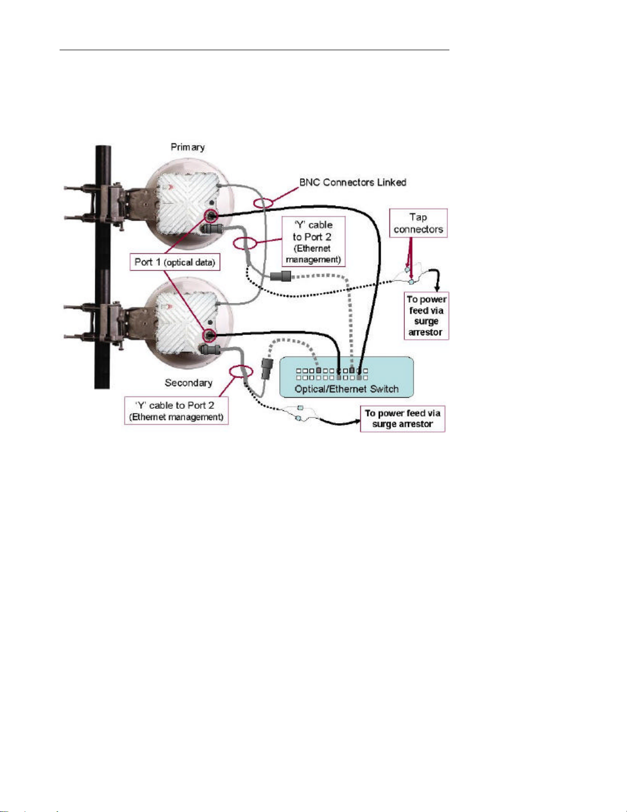
DragonWave Inc.
54
Figure 11-3 Redundancy Connections – 2 wire option – optical interface
NOTE: For clarity, the Transtector surge arrestor has been omitted from the diagram. Both the
Ethernet management feed to Port 2 and the power feed, via Port 2, must be protected from
transients.
Horizon Compact Release 1. 01.01 Wireless Ethernet Product User Manual – Volume 1
Page 65
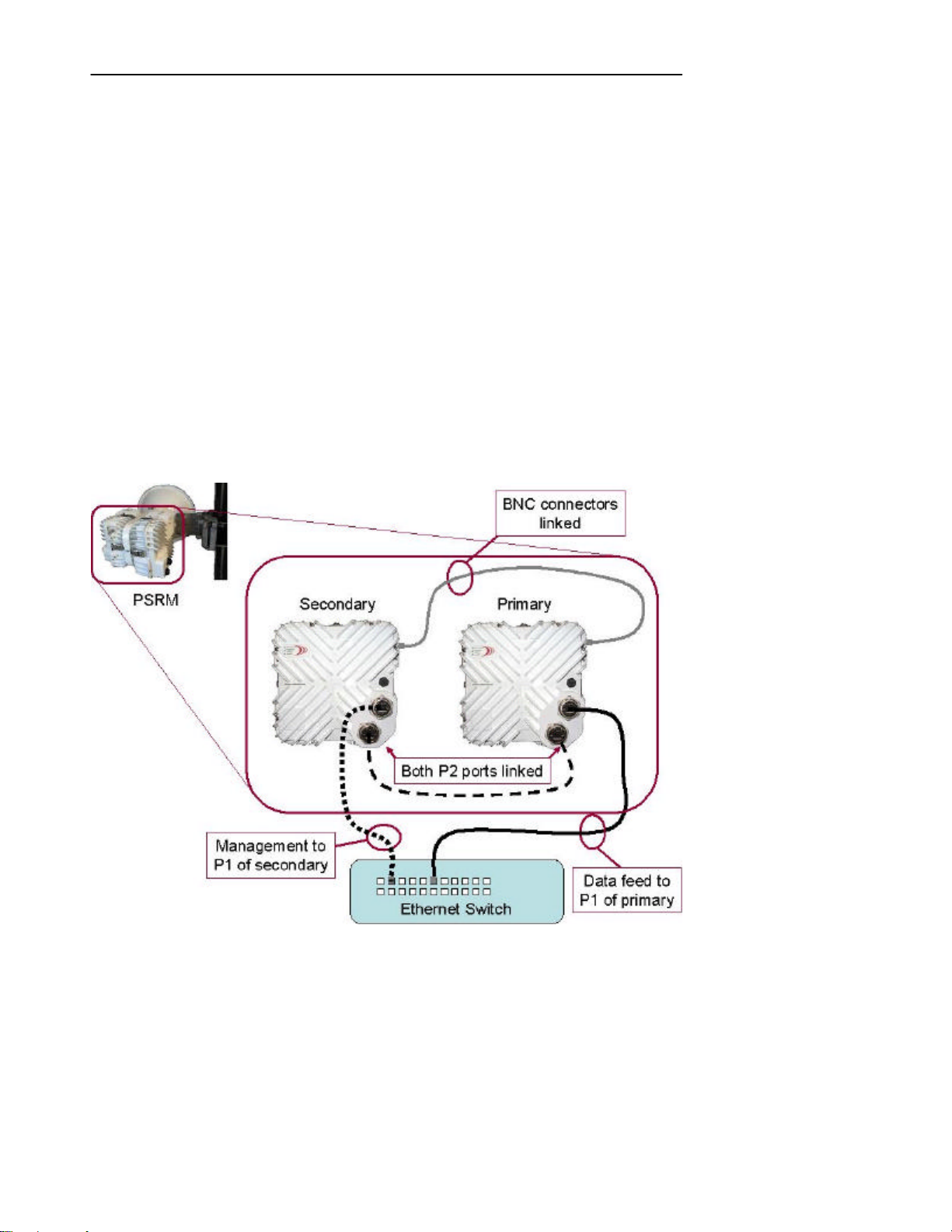
Advanced Configuration Features
55
11.13.3 Single Wire Option with the PSRM
The “single wire” option is so named because only one data feed is required to be connected to the two
interconnected Horizon systems mounted on the PSRM.
The PSRM supports system redundancy by connecting two Horizon units to a single antenna. Only one of
the radios of the mounted systems may operate at any one time. Both systems have the identical polarity,
either both vertically or both horizontally polarized. One system is configured as the Primary and the other
as the Secondary. Note that the terms “primary” and “secondary” relate solely to the internal functions of
the units and has no relationship to which radio is in stand-by or which is carrying traffic.
Port 1 of the primary unit carries the data feed, with Port 2 of both units interconnected. Port 1 of the
secondary unit handles management traffic. The secondary unit has to be configured for in-band
management and the primary unit configured for out-of-band management.
Switching from the active unit to the stand-by unit is determined by the configuration of the Horizon
Compact units and does not depend on connected Ethernet switches.
After a redundancy switch, once the first unit is able to return to carrying traffic, a manual switch is
required, via a CLI command, to return traffic to the first unit.
Figure 11-4 Redundancy Connections – Single wire option – copper interface
NOTE: For clarity, the PonE power adapter and surge arrestor have been omitted from the
diagrams. Both Port 1 Ethernet connections and the power feed via Port 1 must be protected from
transients.
Horizon Compact Release 1. 01.01 Wireless Ethernet Product User Manual – Volume 1
Page 66
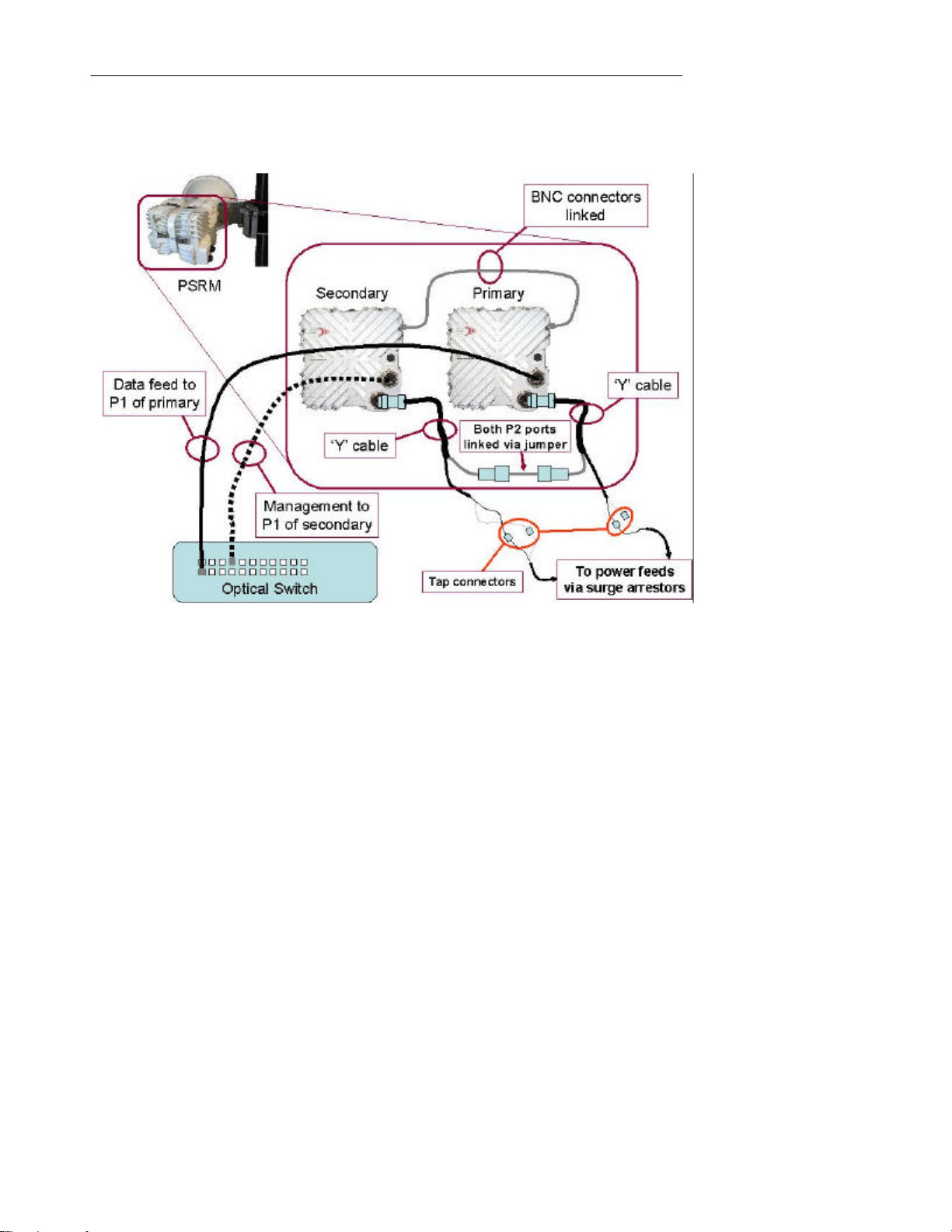
DragonWave Inc.
56
Figure 11-5 Redundancy Connections – Single wire option – optical interface
NOTE: For clarity, the Transtector surge arrestor has been omitted from the diagram. The power
feed must be protected from transients.
Horizon Compact Release 1. 01.01 Wireless Ethernet Product User Manual – Volume 1
Page 67

Advanced Configuration Features
57
This page left blank intentionally
Horizon Compact Release 1. 01.01 Wireless Ethernet Product User Manual – Volume 1
Page 68

12.0 Horizon Management
The Horizon Compact system can be fully managed locally or remotely. Horizon Compact supports Telnet
access, SNMP management and a Web interface accessible through the IP network. The entire
Command Line Interface (CLI) command set is available through Telnet. The entire list of system
parameters is available through SNMP access. The Web interface provides access to system
configuration and performance parameters. In-band and out-of-band management options are available.
12.1 In-band and Out-of-band Managemen t
The Horizon Compact contains a dual NIC which has two 10/100/1000 Base-t Ethernet ports. These are
labelled Port 1 and Port 2. The system may be configured to use EITHER Port 1 (in-band), OR Port 2
(out-of-band) for management traffic. Management traffic includes:
1. Telnet traffic and associated CLI commands
2. SNMP management
3. ping
4. FTP, used for configuration backup and restore and software upgrades.
All management functions that are available on Port 1 are also available on Port 2. Both ports may be
configured to operate with or without management VLANs (see Section 11.2).
The key points to consider when choosing the network management configuration are as follows:
• Port 1 is always used for customer data traffic. It is not possible to send customer data
traffic over Port 2.
• Port 1 can be configured to support management traffic in addition to customer data
traffic. Use the CLI command set network management interface port1 then press
Enter. The default configuration is for management data traffic to be carried over Port 1.
Both ends of the link can be managed when Port 1 is set as the management interface.
• Port 2 can only be used for management. Port 2 does not carry any customer data
traffic. Port 2 is disabled by default and can be enabled by using the CLI command set
network management interface port2.
12.1.1 Management through Port 1 (in-band)
Port 1 is always used to carry customer data traffic and operates at rates of up to 400 Mbps over the
radio link, from the local Horizon Compact system through to the far end Horizon Compact system.
Management is set to Port 1 (in-band) by default and management using Telnet, SNMP and Web
interface are supported. To enable in-band management on a system that has been set to out-of-band
management (Port 2), use the CLI command set network management interface port1 then press
Enter.
When the network management interface is set to "port1" all management traffic must arrive on Port 1, or
it will be ignored by the syste m. Configuration and management of the Horizon Compact system can be
accomplished through a Telnet, or SSH, session, and although the Telnet session is intermixed with user
traffic, the Telnet session occupies very little bandwidth (in the order of kbps) and therefore has almost no
effect on user traffic throughput.
A Telnet, or SSH, session can be established through one Horizon Compact system, over the radio link to
the far end Horizon Compact system, allowing management of both ends of the link.
Management of the Horizon Compact system can also be performed through a VLAN using 802.1Q
VLAN tagging. Management through VLAN offer s increased access security. Refer to Section 11.2 for
more information.
Horizon Compact Release 1. 01.01 Wireless Ethernet Product User Manual – Volume 1
Page 69

Horizon Management
59
12.1.2 Management through Port 2 (out-of-band)
Port 2 is available for out-of-band management purposes only. It does not carry customer data traffic. It
has been designed to be used in conjunction with a management overlay network that is separate from
the customer data network. Th e management overlay network is typically extended back to the Network
Operations Center.
To select out -of-band management use the CLI command set network management interface port2
and press Enter. This allows management of the near end unit only. To gain access to the far end unit
use the CLI command set network management interface port2 extended and press Enter. Note: With
this “extended” command, an Ethernet connection must NOT be present on Port 2 of the far end system
otherwise a network loop will be created.
Port 2 supports management of the Horizon Compact system through Telnet sessions , SNMP and the
Web interface. When the management interface has been set to "port2", all management traffic must
arrive on Port 2, otherwise it is ignored by the system. Customer data traffic continues to be carried over
Port 1.
12.2 Telnet Access
Once correctly configured, the Horizon Compact is accessible through a Telnet session using Super
User, NOC and Admin level user accounts. Refer to Appendix A for details of CLI commands. The
Horizon Compact system can be completely configured, tested and managed through a Telnet session.
The Telnet function is enabled by default but can be disabled within the Horizon Compact system. Use
the CLI command set telnet [on/off] to enable or disable Telnet access.
12.3 Secure Shell Access Security
Telnet sessions over a network, such as the Internet, are not secure. User names and passwords, as well
as commands and system responses, are transmitted in clear text during a Telnet session. A secure shell
(SSH) protocol can be enabled in the Horizon Compact system to ensure that access to the units is
restricted to authorized clients. Horizon Compact uses the Secure Shell SSH2 server programme to
create the secure environment for Telnet ses sions. SSH2 is a recognised industry standard, encrypting,
security programme. When enabled, SSH encrypts the entire Telnet session, including all usernames,
passwords, commands and responses from the system. SSH also verifies that you are talking to the
desired server by means of an authentication process using a “fingerprint”. The “fingerprint” is a unique
identifier found only on the desired server.
Enable/disable SSH by issuing the CLI command set ssh server [on/off] then press Enter.
The server “fingerprint” can be returned by issuing the CLI command get ssh server fingerprint then
press Enter.
A Secure Shell client programme needs to be installed on any computer which is to be used to manage a
Horizon Compact system with SSH enabled. A free SSH client programme (PuTTY) is available on the
Web.
Note that both SSH and Telnet can be enabled at the same time. To ensure security, once SSH has been
enabled, disable Telnet.
12.4 Supported SNMP Versions
DragonWave Horizon Compact systems support three versions of SNMP.
• Version 1 (SNMP v1) is the initial implementation of SNMP.
• Version 2 (SNMPv2c) is the second release of SNMP, which has additions and enhancements to
data types, counter size and protocol operations.
• Version 3 (SNMPv3) is the most recent version of SNMP. The functionality of SNMPv1 and
SNMPv2c remain intact, but SNMPv3 has significant enhancements to administration and
security.
Horizon Compact Release 1. 01.01 Wireless Ethernet Product User Manual – Volume 1
Page 70
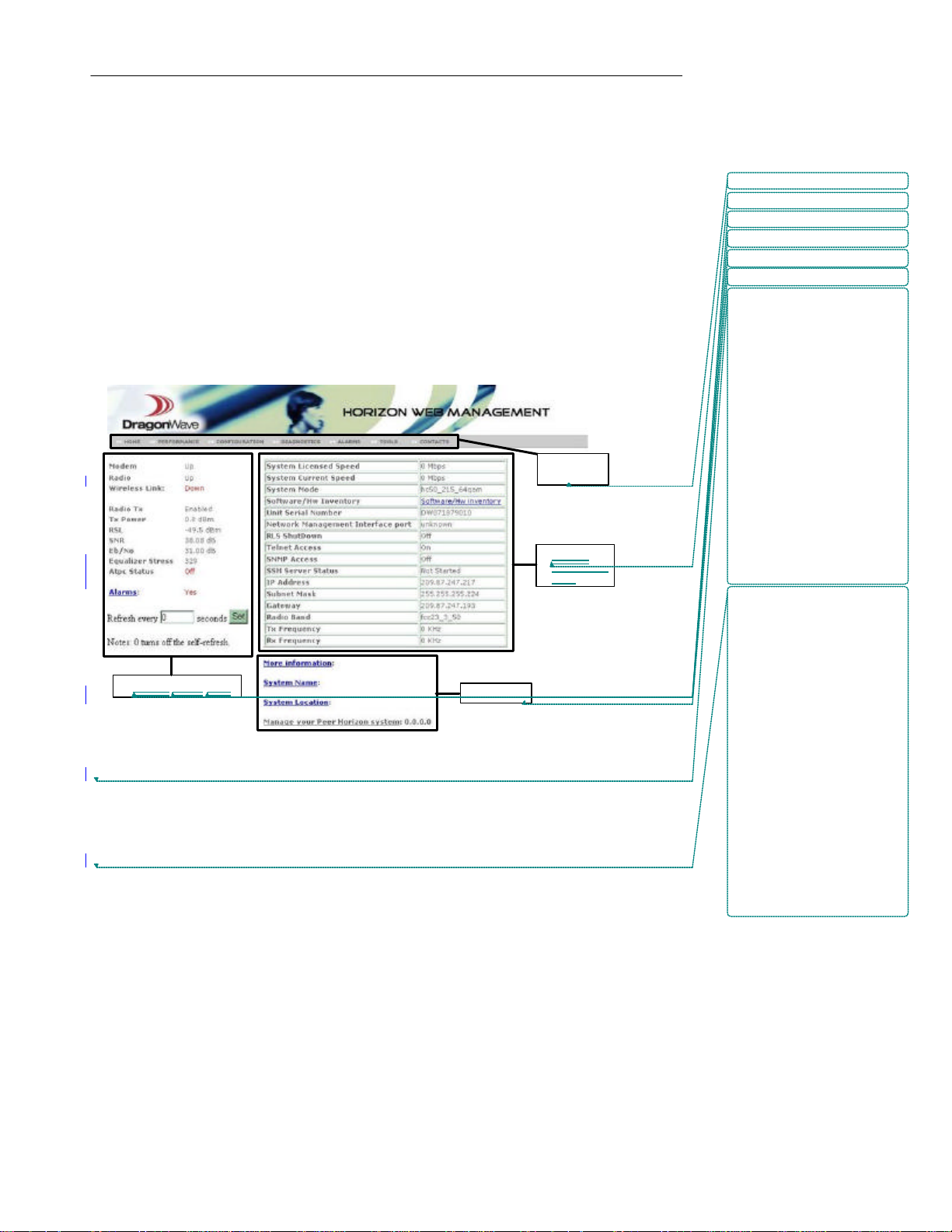
DragonWave Inc.
System
Status
Pane System
Pane
Sub-menu
Navigation
Bar
Deleted:

Deleted:

60
SNMPv3 is an interoperable standards-based protocol that provides secure access to devices by
authenticating and encrypting packets over the network. The security features provided in SNMPv3 are
as follows:
• Message integrity
• Authentication
• Encryption
SNMP configuration is covered in detail in Volume 2.
12.5 Web Interface
The Horizon Compact Web interface runs in a standard browser. To log on see Section 6.1.3.
Formatted: Font: 8 pt, Bold
Formatted: Font: 8 pt, Bold
Formatted: Font: 8 pt, Bold
Formatted: Font: 8 pt, Bold
Formatted: Font: 8 pt, Bold
Formatted: Font: 8 pt, Bold
12.5.1 Home Screen
The Home Screen (window) is divided into 3 sections (panes). The navigation bar displays seven menu
options. The status pane on the left is used to monitor the system health and link performance. The
system information pane on the right displays system parameters and allows configuration changes.
Figure 12-1 Web Interface - Home Screen
System Status Pane
The main screen displays system status in the left hand pane. The information can be continually
refreshed. The default is no self -refresh (set to 0 seconds). Click on the “Set” button to manually refresh.
The maximum refresh rate is 99999 seconds. The minimum refresh rate is 3 seconds. Setting the selfrefresh rate also causes the Performance and Alarms screens to be refreshed at that rate.
System Information Pane
The system information pane contains information on the Horizon Compact type, management settings,
IP address information, and frequency settings. This pane is not updated automatically. The user must
refresh the screen either by using the browser's refresh button or by clicking on the Home button within
the navigation bar in order to update the system information pane.
Information


Horizon Compact Release 1. 01.01 Wireless Ethernet Product User Manual – Volume 1
Page 71

Horizon Management
Deleted:

Deleted:
queue
61
Sub-menu Options
The main screen has four Sub-menu options :
• More Information - opens a window and displays a summary of the system
configuration.
• System Name - link to the System Configuration page. If this field has been previously
configured then the value is displayed
• System Location - link to the System Configuration page. If this field has been
previously configured then the value is displayed
• Manage your Peer Horizon system : [IP address] - links to the login screen of the peer
node (provided the peer node has had its IP address configured). This provides the user
with a web browser interface to each end of the Horizon Compact link.
• Navigation Bar - Click on the navigation bar across the top of the page to navigate to
different screens. Each menu option displays a single screen.
12.5.2 Performance Screen
The performance screen displays the traffic statistics for the Horizon Compact link. There are three
groups of statistics reported:
1. Ethernet traffic statistics from the point of view of the modem NIC in and out from the
local Ethernet cable (payload) and 802.1P priority Queues
2. Modem-to-modem communication for Port 2
3. Modem-to-modem communication for Port 1
This screen is updated at the rate specified in the refresh rate text box in the System Status Pane .


12.5.3 Configuration Screen
The main configuration screen provides hypertext links to each of the configuration sections within the
Horizon Compact system. To navigate to the individual sections, click on the hypertext link. The
Configuration screen allows the user to access the following sections :
System Configuration Automatic Transmit Power Control (ATPC) Configuration
IP Configuration Automatic Adaptive Modulation (AAM) Configuration
Frequency and Port configuration SNTP Configuration
SNMP Trap Hosts Configuration Logs Configuration
SNMP Managers Configuration RADIUS Client Configuration
SNMP V3 Managers Configuration Ethernet Quality of Service
SNMP Traps Configuration
12.5.4 Diagnostics Screen
The diagnostics screen has a link that directs you to the DragonWave support Web page, where you can
download diagnostics programmes.
Horizon Compact Release 1. 01.01 Wireless Ethernet Product User Manual – Volume 1
Page 72

DragonWave Inc.
62
12.5.5 Alarms Screen
The Alarms screen displays the current status of the alarms withi n the Horizon Compact system and the
total accumulated time the alarm has been present (in seconds). The total accumulated time may indicate
the current alarm has been active for the timeframe indicated, or may indicate the alarm has occurred
multiple times for a total time equaling the displayed value (See 12.9 for a list of alarms) . This screen is
updated at the rate specified in the refresh rate text box on the left hand side of the page. The default is
no self-refresh (set to 0 seconds).
12.5.6 Tools Screen
This screen provides you access to the Link Alignment Tool and Link Planning Tool. The Link Alignment
Tool provides a continuously updated RSL reading for link alignment operations as an alternative to using
a DVM connected to the BNC field strength monitor connector (see Section 9.1).
12.5.7 Contacts Screen
If you need to contact DragonWave all the information you need is shown on this screen.
12.6 Horizon Compact SSL Web Server
The Horizon Compact Web server can be configured for Secure Sockets Layer (SSL). The Web server
may be configured to operate in standard mode or in SSL mode. The Horizon Compact SSL Web server
is HTTP 1.0/1.1 compliant, features full support of HTML 2.0, 3.2, 4.0 and supports SSL 3.0.
Secure Sockets Layer, SSL, is the standard security technology for creating an encrypted link between a
Web server and a browser. This link ensures that all data passed between the Web server and browser
remain private and integral. In order to be able to generate an SSL link, a Web server requires an SSL
Certificate.
In order to invoke SSL on the Horizon Compact W eb server, an SSL certificate must be generated on the
Horizon Compact. Horizon Compact uses an embedded SSL Web server from Allegro Software
Development Corporation. Once generated, the certificate may be held as a private certificate or it may
be registered with a Trusted Certificate Authority such as:
• Allegro Software Development Corporation
• Microsoft Root Authority
• Thawte Server
• GTE Cybertrust Root
• VeriSign RSA Secure Server
SSL access can be enabled on a per -user group basis. SSL access can be invoked for the Super User,
for all NOC accounts, for all Admin accounts, or any combination of the three. Once SSL access has
been enabled for the user group then all members of that user group must use SSL to connect to the
Horizon Compact Web browser. Even if SSL access is not required for the user group, those users may
access the Horizon Compact Web browser through HTTPS (SSL) as a security measure.
12.6.1 Generating a Certificate on Horizon Compact
In order to generate an SSL certificate on Horizon Compact, the user must be logged in as either a NOC
or Super User access level. The SSL certificate is tied to the Horizon Compact IP address. If the Horizon
Compact IP address is changed, then the SSL certificate should be regenerated. Otherwise the browser
SSL session will allow access but it will report that the certificate is invalid. In this situation, it is the
browser user's responsibility to verif y that the proper Horizon Compact is being accessed and that the
invalid certificate is due to an IP address change.
Horizon Compact Release 1. 01.01 Wireless Ethernet Product User Manual – Volume 1
Page 73
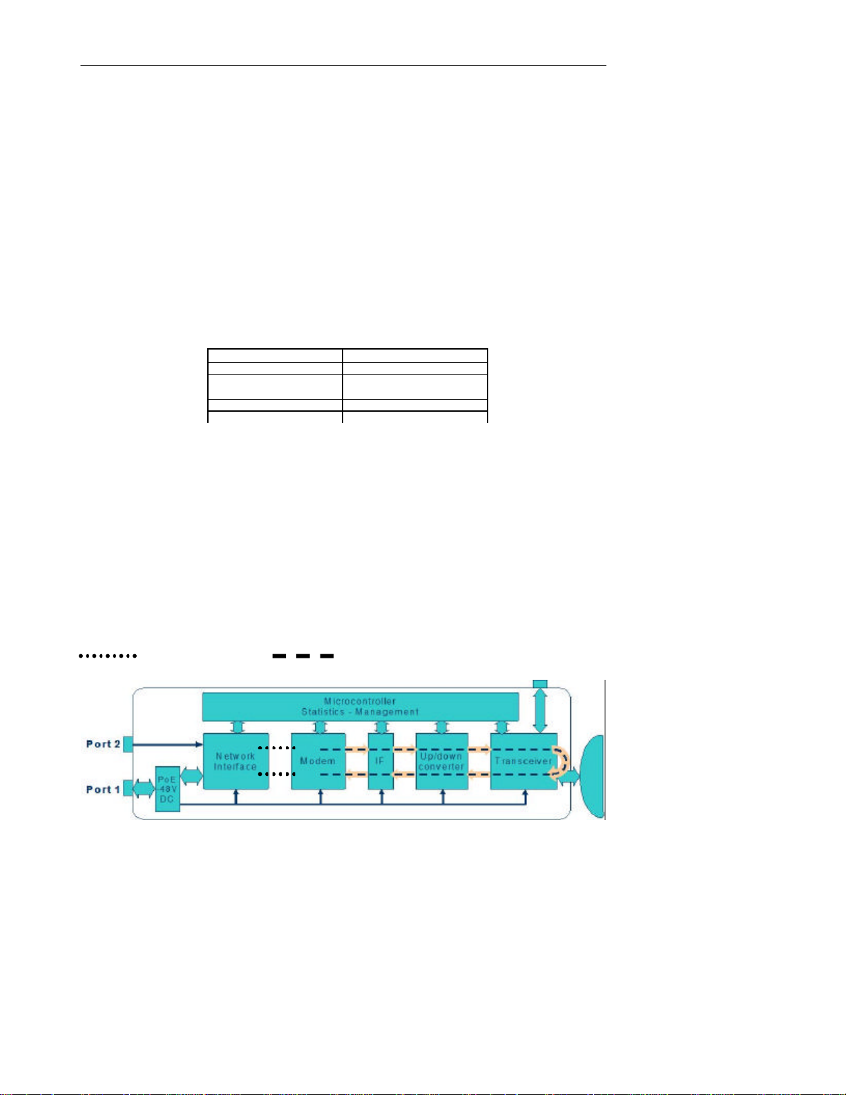
Horizon Management
63
12.7 Event and Performance Logs
The Horizon Compact system supports two logs, the Events Log and the Performance Log. Each can be
used to trace the behaviour of the system over time.
The Events Log is invoked or disabled by issuing the CLI command set logging [on/off]. This log records
alarm and reset events. Approximately 17,500 events can be captured by the Events log. Once the log is
full the o ldest entries are overwritten. Use the CLI command get log entries and press Enter, to display
log entries. Use Ctrl C to abort the listing.
Issuing the CLI command set performance logging [on/off] enables or disables the Performance Log.
This log collects system performance information at time intervals that are configured using the CLI
command set performance log interval [hh:mm:ss].
Use the CLI command get performance log and press Enter, to display a list of Performance Log
entries. Use Ctrl C to abort the listing.
Between 6000 and 8000 entries can be logged before the Performance Log memory is full. Once the
memory is full, new entries will overwrite the oldest entries. The following table assumes that an average
of 7000 entries will occur before memory overflow. If the memory accepts more entries, then the log
duration before overflow will be extended.
Logging Interval Log Duration
15 secs (minimum) ~ 29 hours
1 minute ~ 116 hours (~ 4.8 days)
15 minutes (default) ~ 73 days (~ 2.4 months)
1 hour ~ 292 days (~ 9.7 months)
24 hours (maximum) 7000 days (~ 19.2 years)
12.8 Radio Loopback
Horizon provides a radio loopback facility for analysis of transmit or receive path issues. Invoking a radio
loopback is service affecting and will stop all data t ransfer. There are two options:
• Straight radio loopback - Ethernet traffic is not looped back to the network, Ethernet traffic is
discarded and the RF portion of the Horizon unit is placed in loopback (see Figure 12-2).
• Radio loopback plus network loopback – Ethernet traffic and the radio are placed in loopback
During the loopback, if the modem transmitter loss of sync alarm is not active, then both the transmitter
and receiver of the Horizon unit under test are functioning correctly. A user configurable time limit can be
applied to the loopback feature (default is 30 seconds) . Once the time limit has expired the loopback will
be automatically removed. Note that the far end transmitter should be muted when analysing the near
end system using the radio loopback feature. The radio loopback is invoked or disabled by issuing the
CLI command set radio loopback [on/off] [time][network].
Figure 12-2 Radio Loopback
Network loopback Straight radio loopback
Horizon Compact Release 1. 01.01 Wireless Ethernet Product User Manual – Volume 1
Page 74

DragonWave Inc.
64
12.9 Alarms List
Use the CLI command get alarms to display a list of active alarms. Alternatively, alarms are listed on the
Alarms page of the Web interface. Active alarms are clearly indicated.
The following list shows the various alarms available:
• Explicit Authentication Failed
• Ethernet Link Down
• Dropped Ethernet Frame Threshold Exceeded
• Bandwidth Utilization Threshold Exceeded
• Modem hardware fault
• Modem receiver loss of signal
• Modem SNR below threshold
• Modem programming error
• Modem transmitter loss of sync
• Modem equalizer stress above threshold
• Radio RSL Below Threshold
• SNTP Servers Unreachable
• RLS Shutdown Activated
• AAM Config mismatch
• Tx power detector below threshold
• Radio current out of limits
• TempComp cal table not available
• Radio temperature out of limits
• Radio Power Amplifier
• ATPC Config Mismatch
• RLS Mismatch
• Frequency File invalid
• AAM running on QPSK modulation
• Synthesizer Unlock
Horizon Compact Release 1. 01.01 Wireless Ethernet Product User Manual – Volume 1
Page 75

Horizon Management
65
This page left blank intentionally
Horizon Compact Release 1. 01.01 Wireless Ethernet Product User Manual – Volume 1
Page 76

13.0 Configuration Backup and Restore
Horizon Compact provides a backup and restore facility for system configuration data and user account
data. The backup and restore uses an FTP server to tr ansfer files. It is recommended to have an FTP
server at your network management site for use with the Horizon Compact backup and restore facilities.
Note that the Super User or a noc user level can perform backup and restore functions.
13.1 System Configuration Backup
The Horizon Compact system configuration can be saved to an FTP server. All system configuration
parameters are backed up, allowing the exact configuration to be replicated.
Use the CLI command: save config ftp:<filename> press Enter
where <filename> is the name of the file to be created on the FTP server. Follow the prompts.
Note that the above command will save the file in the root directory of the ftp server. Adding the path
information to the file name will allow you to save it in a specific directory on the ftp server.
13.2 System Configuration Restore
The Horizon Compact system configuration can be retrieved from the FTP server on which it was backed
up. All system configuration parameters are restored, allowing the exact configuration to be replicated.
Use the CLI command: copy ftp: <filename> press Enter
where <filename> is the name of the file to restore to the Horizon Compact . Follow the prompts.
Note that the above command will retrieve the file from the root directory of the ftp server. Adding the path
information to the file name will allow you to retrieve it from a specific directory on the ftp server.
13.3 User Account Configuration Backup
The Horizon Compact system user account configuration can be saved to an FTP server. All user
account parameters are backed up, allowing the exact configuration to be replicated.
Use the CLI command: save users ftp:<filename> press Enter
where <filename> is the name of the file to be created on the FTP server. Follow the prompts.
Note that the above command will save the file in the root directory of the ftp server. Adding the path
information to the file name will allow you to save it in a specific directory on the ftp server.
13.4 User Account Configuration Restore
The Horizon Compact system user account configuration can be retrieved from an FTP server. All user
account configuration parameters are restored, allowing the exact configuration to be replicated.
Use the CLI command: copy ftp: <filename> press Enter
where <filename> is the name of the file to restore to the Horizon Compact.
Note that the above command will retrieve the file from the root directory of the ftp server. Adding the path
information to the file name will allow you to retrieve it from a specific directory on the ftp server.
Horizon Compact Release 1. 01.01 Wireless Ethernet Product User Manual – Volume 1
Page 77

This page left blank intentionally
Horizon Management
67
Horizon Compact Release 1. 01.01 Wireless Ethernet Product User Manual – Volume 1
Page 78

14.0 Software Upgrades
From time to time new software loads are made available that may add new features to the Horizon
Compact system. You can download new software remotely using File Transfer Protocol (FTP).
Use the Command Line Interface (CLI) via Telnet and invoke the FTP with either a local FTP server that
is on the same network as the Horizon Compact system, or use DragonWave’s FTP server site available
through the Internet. The Horizon Compact can interact with the most popular FTP servers on a variety of
operating systems. Anonymous FTP, as well as a user –supplied username and password are supported.
14.1 Single System
Log into the system via Telnet and use the CLI command copy ftp: <filename> and press Enter. Where
<filename> is the name of the software load file in the format omni_x.y.z.hex and includes any path
information.
You will be prompted for the IP address of the FTP server. The FTP server will then prompt you for user
name and password.
Once the download is complete you will need to use the CLI command save mib and press Enter.
The new software is now saved in non volatile memory, but not yet in use.
Note that traffic is not affected during the software download process.
To make the new software load active requires the system to be reset. This is traffic affecting .
To activate the new software load use the CLI command reset system and press Enter. Then press
Y. The system will reset and load the new software.
14.2 Multiple Systems
A batch mode software upgrade programme is available from DragonWave on request. This Unix based
programme uses a flat file listing of all IP addresses of units on a network. It will perform simultaneous
upgrades of multiple units. The number capable of being upgraded simultaneously is limited only by the
number of active FTP sessions allowed by the on -net FTP server.
Horizon Compact Release 1. 01.01 Wireless Ethernet Product User Manual – Volume 1
Page 79

This page left blank intentionally
Horizon Management
69
Horizon Compact Release 1. 01.01 Wireless Ethernet Product User Manual – Volume 1
Page 80

Appendix A – List of CLI Commands
Command Syntax Summary (alpha order)
? (help)
copy [ftp:filename]
create ssl certificate
delete mib [newest|both]
delete radius server [index]
diagnose aam
downgrade system licensed speed [speed]
erase log
erase performance log
exit
get aam status
get alarms
get alarms counter
get alignment
get air interface authentication type
get antenna diameter
get atpc stat us
get authentication failure action
get authenticated peer
get authentication status
get backup ipconfig
get bandwidth utilization threshold
get bandwidth utilization status
get config commands
get cos default value
get cos expedite queue
get cos qinq itag
get cos qinq otag
get cos queue cir
get cos queue mapping
get cos queue cbs
get cos type
get date time
get default ipconfig
get default gateway
get dropped frames threshold
get enet address
get enet config
get enet speed
get enet status
get frequency bank
get frequency file crc
get frequency file status
get group authentication key
get health
get http secure access [Admin|Noc|Super]
get hw inventory
get ip address
get install type
get leds
get licensed speed count
get logging
get log entries
get maximum f rame size
get modem modulation
get modem statistics
get network management interface
get network protocol strict
get omni file crc
get optical transmitter state
get pause state
get performance log
get performance logging
get performance log interval
get programmed frequency
get qos
get radio band
get radio loopback
get radio statistics
get radio status
get radio transmitter state
get radius servers
get radius server retransmit
get radius server timeout
get radius server deadtime
get radius super user authentication
get redundancy link monitor parameters
get redundancy mode
get redundancy override
get redundancy partner information
get redundancy secondary enet state
get redundancy status
get rls
get rls link enable
get rls link monitor parameters
get rls link control
get rls make rsl
get rls signal fault parameters
get rls status
get rsl threshold
get sessions
get snmp access mode
get snmp managers
get snmp set request
get snmp traps
get snmp trap hosts
get snmpv3 managers
get snmpv3 trap hosts
get snr threshold
get sntp
get sntp offset
get ssh server
get ssh server fingerprint
get ssl certificate status
get subnet mask
get super user
get sw inventory
get sw version
get system licensed speed downgrade information
get system mode
get system speed
get system summary
Horizon Compact Release 1. 01.01 Wireless Ethernet Product User Manual – Volume 1
Page 81

Appendix A 71
get system redundancy
get telnet access
get traffic statistics
get transmit power
get unique peer authentication key
get user accounts
get user session
get vlan tag
get vlan tagging
get web server
kill ssh sessions
list [ftp:file/directory/]
lo
ping [-w timeout][ -n count][-t][ip address]
reset [system / modem]
save config [ftp:filename]
save log [ftp:filename]
save mib
save performance log [ftp:filename]
save users [ftp:filename]
set aam [on/off]
set admin user
set air interface authentication type [type]
set authentication failure [action]
set alarms counter [0]
set alignment [on/off]
set antenna diameter [index of diameter]
set atpc [on|off][coordinated power]
set bandwidth utilization threshold [threshold][time]
set cos default value [0-7]
set cos expedite queue [on|off]
set cos qinq itag [protocol id]
set cos qinq otag [protocol id]
set cos queue cir [0-100,0-100,0-100,1-100]
set cos queue mapping [mapping]
set cos queue cbs
set cos type [cos_vlan][cos_qinq_itag][cos_qinq_otag]
set current channel index
set date time [dd/mm/yyyy hh:mm:ss:ms]
set default gateway [ip address]
set dropped frames threshold [threshold][time]
set enet config [port1|port2]
set enet speed [port1|port2] speed[10|100|1000|auto]
AutoNeg[auto]
set frequency bank
set group authentication key [key]
set http secure access [Admin|Noc|Super] [on|off]
set ip address [address]
set logging [on|off]
set maximum frame size [1600-9600]
set network management interface [port1|port2|port2
extended]
set network protocol strict [on|off]
set noc user
set optical transmitter state [on|off]
set pause state [on|off]
set performance logging [on|off]
set performance log interval [hr:min:sec]
set programmed frequency [index]
set qos [on|off]
set radio transmitter state [enable|disable]
set radio band [band]
set radio loopback [on|off]
set radio rxgain
set radio txgain
set radius server key [index] [key]
set radius server host [index] [ip address]
set radius super user authentication strict [on|off]
set redundancy link monitor parameters
set redundancy mode
set redundancy override [primary|secondary|
manual|auto]
set redundancy standby enet state [on/off/pulse]
set redundancy state switch [on]
set rls [on|off]
set rls link enable [on|off]
set rls link monitor parameters [dn2up frame error]
[up2dn frame error] [dn2up samples] [up2dn samples]
[sample time]
set rls link control [on|off]
set rls make rsl [rsl value][time]
set rls signal fault parameters [time][% error]
set rsl threshol d [threshold][time]
set snmp access mode [v1|v2c|off]
set snmp manager [mgr index] [ip address]
[enable|disable] [community string]
set snmp set request [on|off]
set snmp trap [trap#] [enable|disable]
set snmp trap host [host#] [ip address]
[enable|disable] [community string]
set snr threshold [threshold]
set snmpv3 trap host enable [index]
set snmpv3 trap host disable [index]
set snmpv3 trap host ip [index] [ip address]
set snmpv3 trap host user [index] [none|des]
set snmpv3 trap host authentication [indes]
[none|md5|sha] [passwd]
set snmpv3 trap host privacy [index] [none|des]
set sntp [on|off]
set sntp default
set sntp offset [hrs]
set sntp server [index] [ip address]
set ssh server
set super user [username] [password]
set system current speed [speed]
set system mode [mode]
set system redundancy [on|off]
set telnet [on|off]
set traffic statistics [0]
set transmit power [power in dB]
set unique peer authentication key [key]
set subnet mask [mask]
set vlan tag [vlan ID (0-4095)] [vlan priority (0-7)]
set vlan tagging [on|off]
set web server [on|off]
upgrade system licensed speed [speed] [key]
Horizon Compact Release 1. 01.01 Wireless Ethernet Product User Manual – Volume 1
Page 82

Appendix B – Safety Information
Safety Information for Radio Equipment
The Federal Communications Commission (FCC), with its action in ET Docket 96-8, has adopted a safety
standard for human exposure to radio frequency (RF) electromagnetic energy emitted by FCC-certified
equipment. DragonWave Horizon Compact meets the uncontrolled environmental limits found in OET- 65
and ANSI C95.1, 1991. Proper operation of this radio according to the instructions found in this manual or
any other product manuals or user guides for the DragonWave family of products or equipment will result
in user exposure that is substantially below the FCC recommended limits.
1. Do not touch or move antenna(s) while the unit is transmitting or receiving.
2. Do not hold any component containing the radio in such a way that the antenna is very
close to or touching any exposed parts of the body, especially the face or eyes , while the
unit is transmitting.
3. Do not operate a portable transmitter near unshielded blasting caps or in an explosive
environment unless it is a type especially qualified for such use.
The design of the high -gain mast mount antennas is such that professional installation is required.
Information sur la sécurité de l’appareil radio
En vertu de l’ET Docket 96-8, la FCC a adopté une norme de sécurité sur l’exposition humaine à l’énergie
électromagnétique de radiofréquence (RF) émise par le matériel homologué par la FCC. L’appareil
Horizon Compact de DragonWave respecte les limites environnementales non contrôlées décrites dans
le bulletin OET-65 et dans la norme ANSI C95.1 de 1991.
Si l’ appareil radio est utilisé selon les instructions décrites dans le présent manuel ou tout autre manuel
de nos produits ou dans le guide de l’utilisateur relatif à la ligne de produits ou équippement de
DragonWave, résultera à des expositions aux champs électromagnétiques sensiblement moins élevés
que les limites recommandées par la FCC.
1. Ne jamais toucher ou dépla cer la ou les antennes lorsque l’appareil fonctionne en mode
de transmission ou de réception.
2. Lorsque l’appareil fonctionne en mode de transmission, tenir les éléments contenant la
radio de manière que l’antenne ne soit pas trop proche des parties du corps exposées
(surtout le visage ou les yeux) ou n ’y touche pas.
3. Ne pas faire fonctionner un émetteur transportable à proximité de détonateurs non
protégés ou dans un milieu explosif, à moins qu’il s’agisse d’un émetteur autorisé.
Les antennes à gain élevé mon tées sur mât sont conçues pour être installées par des professionnels.
Horizon Compact Release 1. 01.01 Wireless Ethernet Product User Manual – Volume 1
Page 83

Appendix C
73
Professional Installation
DragonWave Horizon Compact devices require professional installation. It is the responsibility of the
installer to be sure that all building and safety codes are met and that the installation is complete and
secure.
The Horizon Compact shall be installed according to local Electrical Safety Codes.
For Canadian installations, the entire equipment installation must comply with Canadian Standard CSA
22.2, No. 60 950, Safety of Information Technology Equipment. For installations in the United States, the
entire equipment installation must be in accordance with Article 810 of the United States National
Electrical Code.
Installations Professionel
Les appareils Horizon Compact de DragonWave doivent être installés par un personnel professionnel. Le
personnel responsable doit s’assurer que l’installation est bien achevée, et qu’elle répond aux exigences
de tous les codes de sécurité.
Une installation faite au Canada doit observer les normes 22.2, numéro 60950 du CSA, Sécurité des
matériels de traitement de l'information. Une installation faite aux États-Unis doit être faite selon les
stipulations de l’Article 810 du United States National Electrical Code.
Lightning Protection
When installed, this equipment is to be connected to a Lightning/Surge Protection Device that meets all
applicable national safety requirements.
Before Ethernet cables enter buildings, voltages shall be clamped down to SELV by Approved type
primary pr otectors.
Protection contre la foudre
L’installation exige aussi que l’appareil soit branché à un parafoudre qui répond à toutes les normes
nationales de sécurité.
Horizon Compact Release 1. 01.01 Wireless Ethernet Product User Manual – Volume 1
Page 84
DragonWave Inc.
74
Electrocution Hazard
Warning
Electrocution Hazard
This product is intended to be connected to a –36 to -60V DC power source (power adapter supplied by
DragonWave Inc.), which must be electrically isolated from any ac sources and reliably connected to
Earth ground. Do not install DragonWave products near any type of power line. Should your antenna or
related hardware come in contact with power lines, severe bodily harm or death could result!
Risque d’électrocution
Avertissement
Risque d’électrocution
Cet appareil est raccordée à une source de tension de –36 a -60V CD (adapteur fourni par DragonWave),
qui doit être isolée de toute autre source de tension et raccordée à une mise à terre isolée. Les produits
de DragonWave ne doivent pas être installés près de ligne à haute tension. Des dommages corporels
sévères et même la mort peuvent survenir si l’antenne ou toute autre pièce viennent en contact avec des
lignes de haute tension Dommage corporel.
Radio Frequency Safety
The installer of this radio equipment must ensure that the antenna is located or pointed
such that it does not emit RF fields in excess of the general population limits as defined by FCC CFR 47,
Part 2.1091, Radiofrequency radiation exposure evaluation for fixed devices & Health Canada limits for
the general population; consult Safety Code 6, obtainable from Health Canada’s website
www.hc-sc.gc.ca/rpb.
RF Radiation Safety Information
The antenna must be located such that humans will not approach within 5m of the forward transmitting
direction of the antenna and 0.46m in all other directions. This distance provides additional safety margin
for the product, as well as minimizing exposure to microwaves.
These calculations were done in accordance with:
1. FCC Radio Frequency Exposure Limits 1.1310
2. Health Canada Safety Code 6 / Industry Canada RSS 102
3. EMF Exposure Directive (99/519/EC)
Information sur la Securité des Radiations des FR
L'antenne doit être localisée de façon à ce que les humains ne puissent pas s'en approcher à moins de
5m dans l'axe de transmission à l'avant de l'antenne et de 0.46m dans toutes autres axes. Ceci la
distance fournit une marge de sûreté additionnelle pour ce produit en minimisant l'exposition aux microondes.
Ces calculs ont été faits selon :
1. L'Exposition De Fréquence Par radio de FCC Limite 1.1310
2. Industrie Canada RSS 102 / De l'Indicatif 6 De Sûreté Du Santé Canada
3. Le Directif d’Exposition De EMF (99/519/EC)
Horizon Compact Release 1. 01.01 Wireless Ethernet Product User Manual – Volume 1
Page 85

This page left blank intentionally
Appendix C
75
Horizon Compact Release 1. 01.01 Wireless Ethernet Product User Manual – Volume 1
Page 86
Appendix C - Regulatory Compliance Information
This section contains information regarding regulatory compliance with the Federal Communication
Commission, Department of Communications and the European Telecommunications Standards Institute
applies to the Horizon Compact radio link.
Federal Communication Commission Declaration of Conformity Statement
This device complies with Part 15 of FCC Rules. Operation is subject to the following two conditions:
1. This device may not cause harmful interference, and
2. This device must accept any interference received, including interference that may
cause undesired operation.
This equipment has been tested and found to comply with the limits of a Class B digital device, pursuant
to Part 15 of FCC Rules. These limits are designed to provide reasonable protection against harmful
interference when the equipment is operated in a residential environment. This equipment generates,
uses and radiates radio-frequency energy, and if not installed and used in accordance with the
instructions, can cause harmful interference. However, there is no guarantee that interference will not
occur. If this equipment does cause interference to radio or television reception, which can be determined
by turning the equipment on and off, the user is encouraged to correct the interference by one of the
following measures:
1. Reorient or relocate the receiving antenna;
2. Increase separation between the equipment and receiver; or
3. Connect the equipment into an outlet on a circuit different from that which the receiver is
connected.
Warning
The Part 15 radio device operates on a non-interference basis
with the other devices operating at this frequency. Any changes
or modification to said product not expressly approved by
DragonWave Inc. could void the user’s authority to operate this
device.
Horizon Compact Release 1. 01.01 Wireless Ethernet Product User Manual – Volume 1
Page 87

Appendix D
77
Department of Communications – Canada - Compliance Statement
This class B Digital apparatus meets all the requirements of the Canadian Interference-Causing
Equipment Regulations.
This device complies with RSS-210 of Industry Canada. Operation is subject to the following two
conditions:
1. this device can not cause harmful interference; and
2. this device must accept any interference received, including interference that can
cause undesired operation.
The use of this device in a system operating either partially or completely outdoors can require the user to
obtain a license for the system according to Canadian regulations. For further information, contact your
local Industry Canada office.
Ministère des Communications – Canada
Déclaration de conformité aux normes canadiennes
Cet appareil numérique de la classe B respecte toutes les exigences du Règlement sur le matériel
brouilleur du Canada.
Cet appareil est conforme à la norme RSS-210 d'Industrie Canada. Son exploitation est soumise aux
deux conditions suivantes :
1. il ne doit pas provoquer de brouillage préjudiciable et
2. il doit tolérer le brouillage reçu, notamment le brouillage susceptible de perturber son
fonctionnement.
Si l'appareil doit être utilisé dans un système qui fonctionne partiellement ou complètement à l'extérieur,
l'utilisateur devra obtenir une licence à cet eff et, conformément aux règlements canadiens. Pour de plus
amples renseignements, communiquer avec le bureau local d'Industrie Canada.
Certification Note From Industry Canada for 24 GHz DEMS
CERTIFICATION NOTE FROM INDUSTRY CANADA: While this equipment meets the technical
requirements for its operation in its rated paired block arrangement, this block arrangement is different
than the 40+40 MHz block arrangement prescribed in documents RSS-191 and SRSP-324.25. The
operation of this equipment IS NOT permitted if the out-of-band and spurious emission limits are not met
at the edge of any contiguous licensed spectrum. It should be noted that all current relevant spectrum
policies, licensing procedures and technical requirements are still applicable. For additional information,
please contact the local Industry Canada office.
European Telecommunications Standards Institute Statement of Compliance
This equipment has been tested and found to comply with the European Telecommunications Standard
ETS 300.328. This standard covers Wideband Data Transmission Systems referred to in CEPT
Recommendation T/R 10.01.
This type of accepted equipment is designed to provide reasonable protection against harmful
interference when the equipment is operated in a residential environment. This equipment generates,
uses, and can radiate radio frequency energy. If the equipment is not installed and used in accordance
with the instruction manual, it can cause harmful interference to radio communications.
Horizon Compact Release 1. 01.01 Wireless Ethernet Product User Manual – Volume 1
Page 88

DragonWave Inc.
78
This page left blank intentionally
Horizon Compact Release 1. 01.01 Wireless Ethernet Product User Manual – Volume 1
Page 89

Copyright © 2000-2007 DragonWave Inc. Printed in Canada. All rights reserved.
Horizon Compact™ Product Manual, 83- 000027-01-01-04
Visit us on the Internet at:
http://www.dragonwaveinc.com/
Appendix D
79
Horizon Compact Release 1. 01.01 Wireless Ethernet Product User Manual – Volume 1
 Loading...