

Page 1

DCT-EDP Rev3.x User Manual
Dragonchip
We bring silicon to life
DragonFLASHTM
1 of 27
DCT-EDP Rev3.x User Manual
.
Dragonchip
Rev1.3
.
Document Revision 1.3 June, 2019
Page 2

DCT-EDP Rev3.x User Manual
Dragonchip
We bring silicon to life
DragonFLASHTM
2 of 27
Rev1.3
Table of Content
1 INTRODUCTION .............................................................................................................. 3
1.1 BOX CONTENTS ................................................................................................................. 3
1.2 USEFUL LINKS .................................................................................................................... 3
2 HARDWARE ..................................................................................................................... 5
2.1 CONTROL INTERFACE ......................................................................................................... 5
3 DEBUG ............................................................................................................................. 6
3.1 HARDWARE SETUP ............................................................................................................. 6
3.2 DEBUG PORT PIN ASSIGNMENT ........................................................................................... 7
3.3 PIN ASSIGNMENT ON POD BOARD....................................................................................... 8
3.3.1 DC6688EMT-1TS-POD Rev2.0 board ................................................................. 8
3.3.2 DC6288EMT-FT-POD Rev2.0 board ................................................................... 8
3.4 SOFTWARE INSTALLATION .................................................................................................. 9
3.4.1 Source Code Template ...................................................................................... 10
3.4.2 Keil Project Settings ........................................................................................... 10
3.5 VIEW MEMORY CONTENT ................................................................................................. 13
3.5.1 DC6688F2SER/F2STR ...................................................................................... 13
3.5.2 DC6688FLB ....................................................................................................... 13
3.5.3 DC6688FLX/FLE/FLT/FL96TE .......................................................................... 13
3.5.4 DC6688FSB/FSX/FSE/FST ............................................................................... 14
3.5.5 DC6688BT ......................................................................................................... 14
3.5.6 DC6288FT ......................................................................................................... 14
3.6 SUPPLEMENTARY INFORMATION ....................................................................................... 14
3.6.1 Limitation ............................................................................................................ 14
3.6.2 Troubeshooting .................................................................................................. 15
.
4 PROGRAMMING ............................................................................................................ 16
4.1 SOFTWARE INSTALLATION ................................................................................................ 16
4.2 HARDWARE SETUP ........................................................................................................... 16
4.3 DC6688FSX .................................................................................................................. 17
4.4 DC6688FST/FLT/BT ..................................................................................................... 18
4.5 DC6288FT ..................................................................................................................... 23
REVISION HISTORY .............................................................................................................. 26
Page 3
DCT-EDP Rev3.x User Manual
Dragonchip
We bring silicon to life
DragonFLASHTM
3 of 27
Rev1.3
1 Introduction
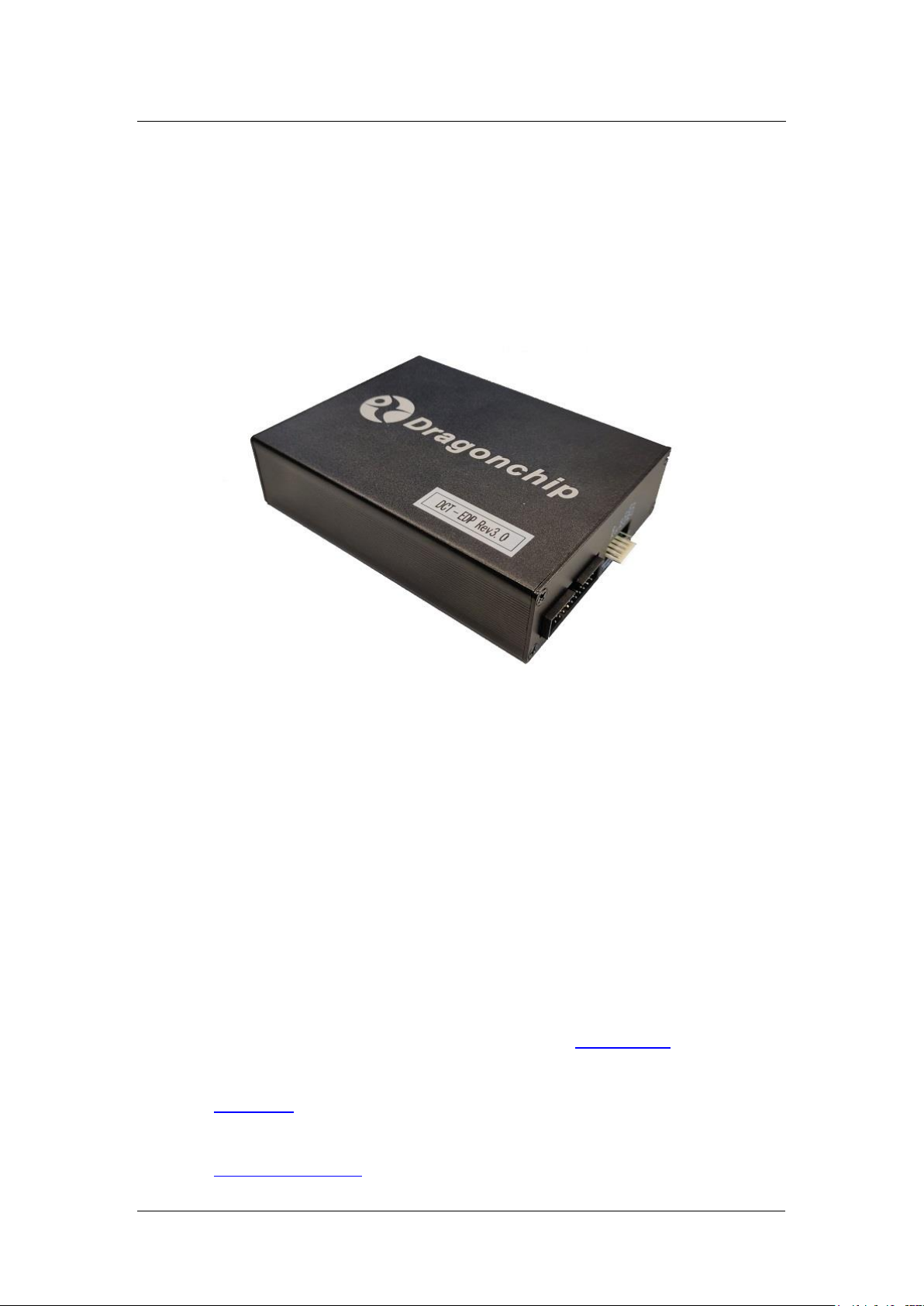
This document aims at describing the operation of the tool ‘DCT-EDP Rev3.x’.
DCT-EDP is primarily used for flash programming and debugging software
running on 8051-based System-on-Chip (SoC) devices from Dragonchip.
.
1.1 Box Contents
1. 1 x DCT-EDP Rev3.x
2. 1 x USB cable
3. 1 x 20-pin flat cable with 2x10 2.54mm connector
4. 1 x 6-pin flat cable with 1x6 2.54 connector
1.2 Useful links
Generally, all the products information is available in our website. Below are
some examples.
1. DC6688
1. Emulator – download latest software installer(Software SLP,
Emulator driver, and Source Code Template in one package) and
user manual
2. Technical website
Page 4

DCT-EDP Rev3.x User Manual
Dragonchip
We bring silicon to life
DragonFLASHTM
4 of 27
2. DC6288
1. Emulator – download latest software installer(Software SLP,
Emulator driver, and Source Code Template in one package) and
user manual
2. Technical website
.
Rev1.3
Page 5
Dragonchip
We bring silicon to life
DragonFLASHTM
5 of 27
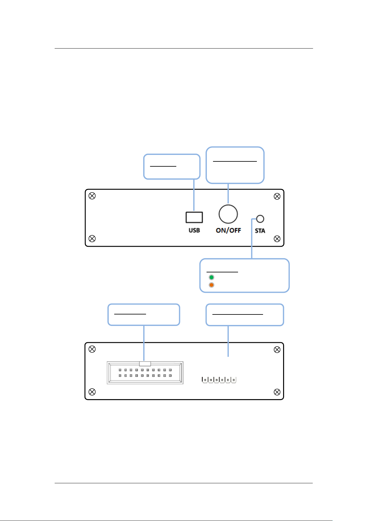
2 Hardware
Debug / Programming
- Connect to PC
Rear panel
Programming Port:
- Connect to IC
Debug Port:
- Connect to IC / POD
Front panel
Debug
Programming
VDD
2.1 Control Interface
DCT-EDP Rev3.x User Manual
.
Rev1.3
USB Port:
ON/OFF Button:
Power ON/OFF
device
Status LED:
Power ON
Front panel have two ports:
1. Debug port
甲、Keil use this port for debug and programming
2. Programming port
甲、Software SLP use this port for programming
SL
VSS
CLK1
PROG
CLK2
Page 6
DCT-EDP Rev3.x User Manual
Dragonchip
We bring silicon to life
DragonFLASHTM
6 of 27
Debug
P/N: DCT-EDP Rev3.0
USB
Target system
SL
Keil
Rev1.3
3 Debug
3.1 Hardware setup
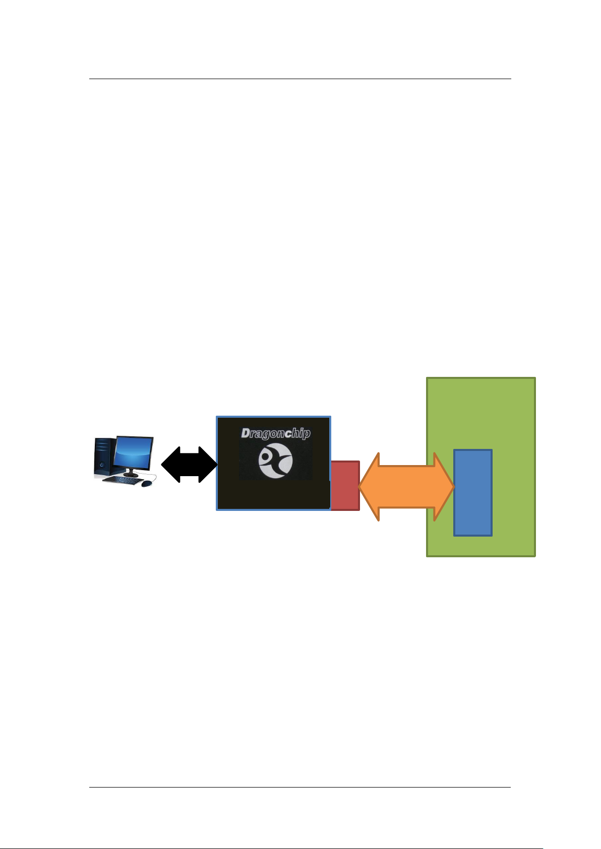
Debug port provides JTAG and SL interface to IC package with JTAG and SL
pins. Prior to entering debug mode in Keil IDE, the firmware will be
downloaded automatically through this SL interface. JTAG interface is used for
debug communication.
There are two cases of connection depending on whether the package
provided with JTAG pins or not.
1. IC package with JTAG pins
.
JTAG
+
IC with JTAG
An example is DC6288FT32N3E. In this case, the debug port can connect
directly to the IC.
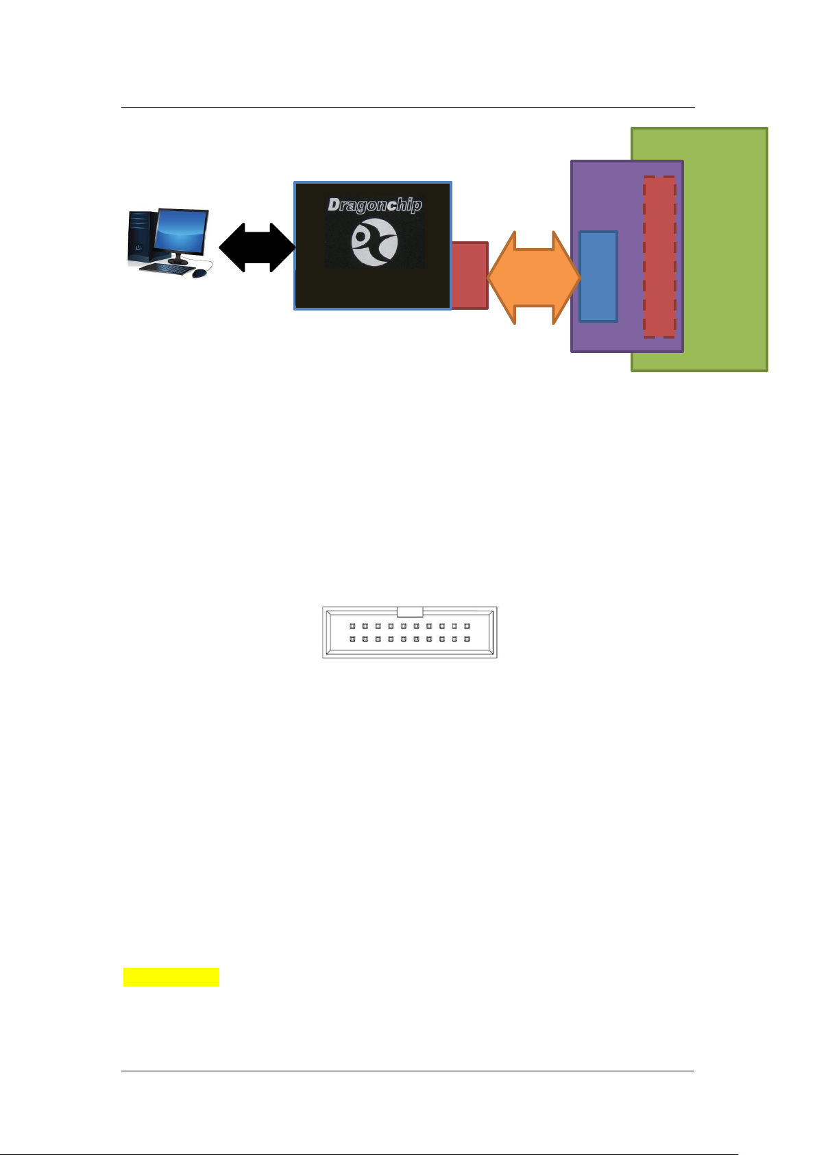
2. IC package without JTAG pins
Page 7
DCT-EDP Rev3.x User Manual
Dragonchip
We bring silicon to life
DragonFLASHTM
7 of 27
Debug
P/N: DCT-EDP Rev3.0
USB
Target system
Keil
POD
Emulator IC
Pin header
JTAG
SL
VSS
Reserved
PROG
TMS
SL
TDI
TDO
CLK2
TCK
CLK1
Reserved
VDD
Rev1.3
+
An example is DC6688FL96TT, TSSOP28 without JTAG pin. The DCT-EDP
has to connect to target system through a POD board.
.
3.2 Debug port pin assignment
VSS
VSS
VSS
VSS
VSS
VSS
VSS
Reserved
Reserved pins must be no connection.
VDD pin, with maximum output current 500mA, should be handled with care to
avoid conflict with the power from self-powered target system. They should not
be connected together unless target system power supplied by VDD pin of
Debug port. If the power of Dragonchip IC is supplied by self-powered target
system, VDD pin of Debug port should be left disconnected.
The following series are compulsory to connect VDD pin of Debug port,
instead of target system.
1. DC6688
2. DC6388
Ribbon cable is strongly recommended for better noise immunity.
Page 8
DCT-EDP Rev3.x User Manual
Dragonchip
We bring silicon to life
DragonFLASHTM
8 of 27
Pin
Description
Pin
Description
1
PD3
2
PD2
3
PC3 4 IRI
5
VDD(3.3V)
6
VSS
7
PC2
8
PD1
9
PC1
10
PD0
11
PC0
12
NC
13
PB7
14
PA0
15
PB6
16
PA1
17
PB5
18
PA2
19
PB4
20
PA3
21
PB3
22
PA4
23
PB2
24
PA5
25
PB1
26
PA6
27
PB0
28
PA7
29
PC5
30
PC4
31
PD6
32
PD5
33
NC
34
PD4
35
NC
36
NC
37
NC
38
NC
39
NC
40
NC
Rev1.3
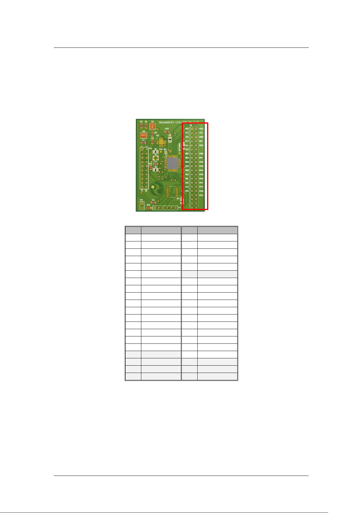
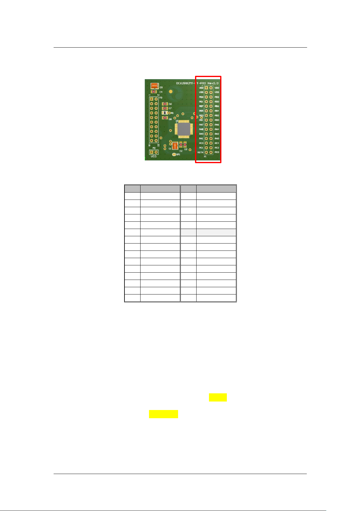
3.3 Pin assignment on POD board
3.3.1 DC6688EMT-1TS-POD Rev2.0 board
This board can support both DC6688FST and DC6688FLT for those packages
without JTAG pins.
.
3.3.2 DC6288EMT-FT-POD Rev2.0 board
Page 9
DCT-EDP Rev3.x User Manual
Dragonchip
We bring silicon to life
DragonFLASHTM
9 of 27
Pin
Description
Pin
Description
1
VDD(3.3V)
2
VDD(3.3V)
3
VSS
4
VSS
5
PD3
6
PD2
7
PD1
8
PD0
9
PB7
10
PB6
11
PB5
12
PB4
13
PB3
14
PB2
15
PB1
16
PB0
17
PA7
18
PA6
19
PA5
20
PA4
21
PA3
22
PA2
23
PA1
24
PA0
25
PC3
26
PC4
27
PC1
28
PC2
29
NC
30
PC0
Rev1.3
This board can support both DC6288FT for those packages without JTAG
pins.
.
3.4 Software Installation
Install the following components in order:
1) Keil PK51 Prof. Developers Kit (recommend v9.55)
It must be installed prior to the following components.
2) Dragonchip ‘DC_TOOL_Rev3.2.1.exe’ or higher which includes the
following items:
a. Source Code Template
b. Emulator Driver
c. Software SLP
Page 10
DCT-EDP Rev3.x User Manual
Dragonchip
We bring silicon to life
DragonFLASHTM
10 of 27
Rev1.3
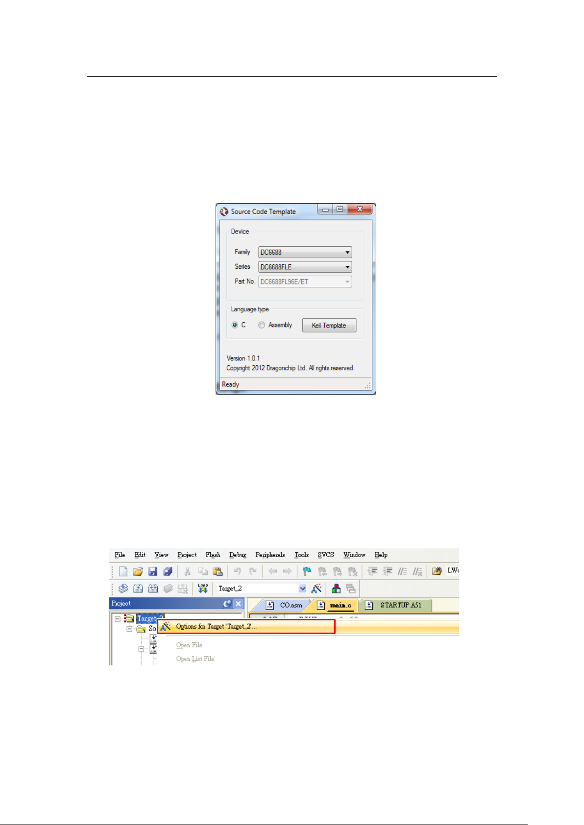
3.4.1 Source Code Template
This useful tool can help to generate Keil Project Templates for various
Dragonchip 8051-based MCU products with all necessary project settings for
using emulators. User can either start the development with the generated
source code template or compare the project settings with their existing Keil
project.
.
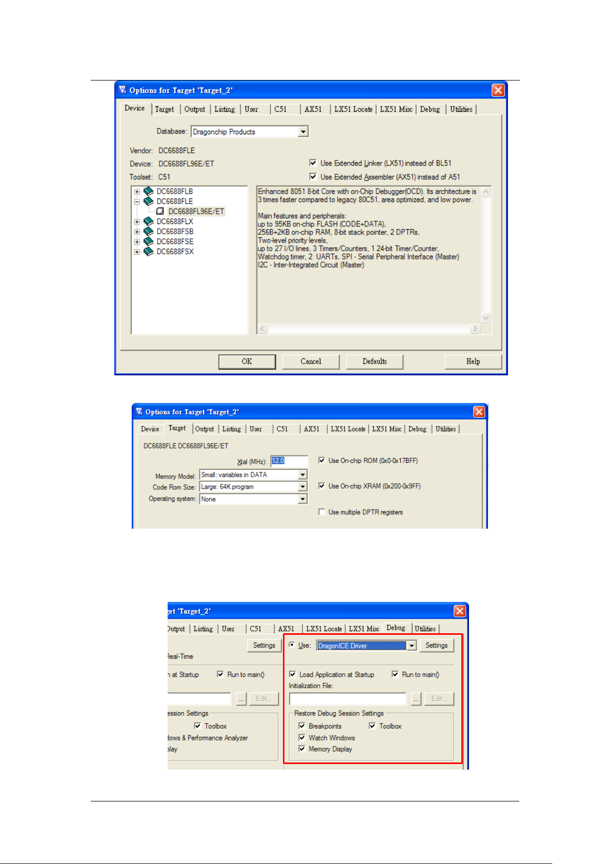
3.4.2 Keil Project Settings
All necessary Keil Project Settings are listed in this section. The settings might
vary from one part no. to another.
For illustration, DC6688FL96E is taken as an example.
1) Enter ‘Options for Target’
2) ‘Device’ Tab - Select DC6688 part from the list.
Page 11
DCT-EDP Rev3.x User Manual
Dragonchip
We bring silicon to life
DragonFLASHTM
11 of 27
Rev1.3
.
3) ‘Target’ Tab
Note: The Clock frequency in this page is invalid setting. The setting should be
selected in ‘Programming Setting’ instead.
4) ‘Debug’ Tab - Follow the settings shown below:
Page 12
DCT-EDP Rev3.x User Manual
Dragonchip
We bring silicon to life
DragonFLASHTM
12 of 27
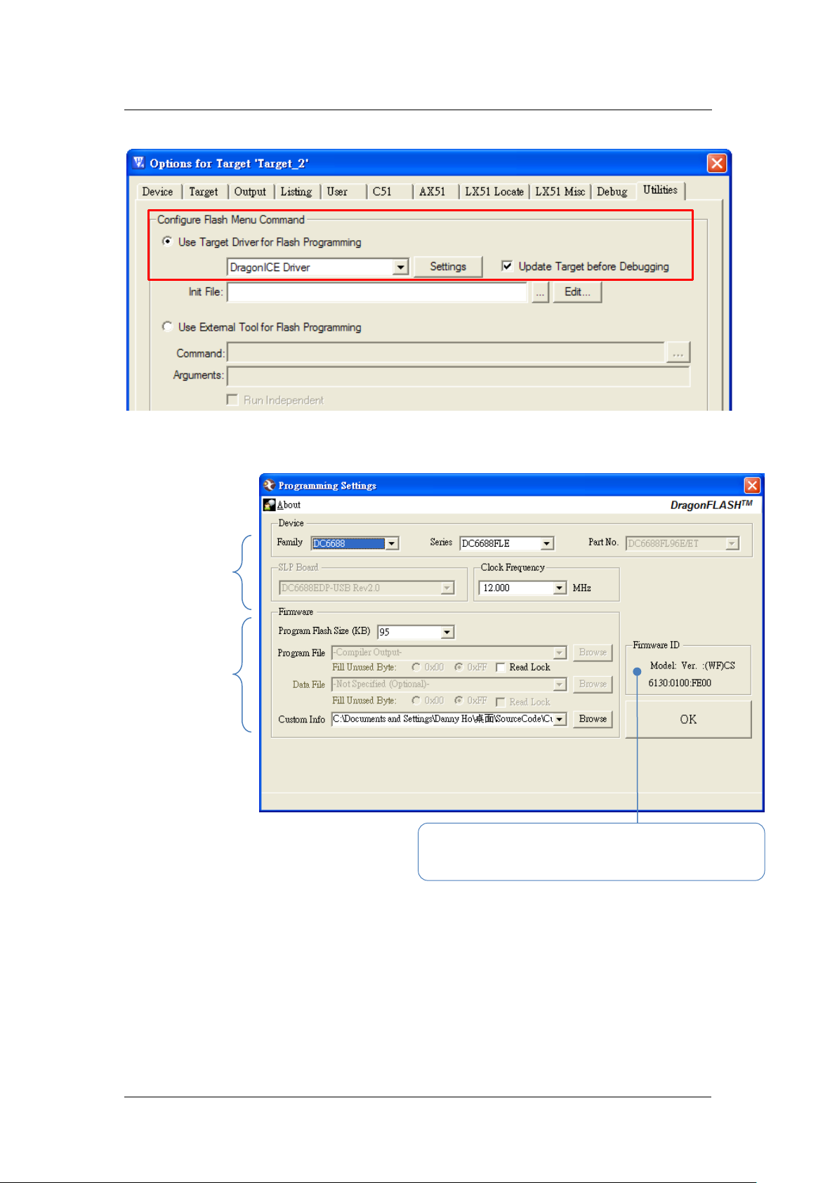
Select Device
Frequency
Select paths of
project folder)
Model (2 bytes) – configure by Custom Info file
Checksum (2 bytes) – generate automatically from Program file
Rev1.3
5) ‘Utilities’ Tab - Follow the settings shown below:
6) Click ‘Settings’ in ‘Utilities’ tab to enter Programming Setting. Input relevant
settings for programming the emulator chip.
.
and Clock
Firmware files
(All these files
should be put
in the Keil
Version (2 bytes) – configure by Custom Info file
Note: Program File does not need to select path.
Page 13
Dragonchip
We bring silicon to life
DragonFLASHTM
13 of 27
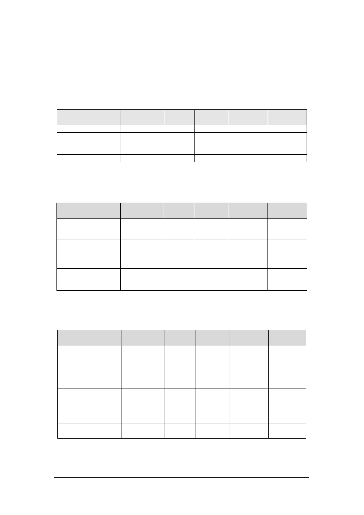
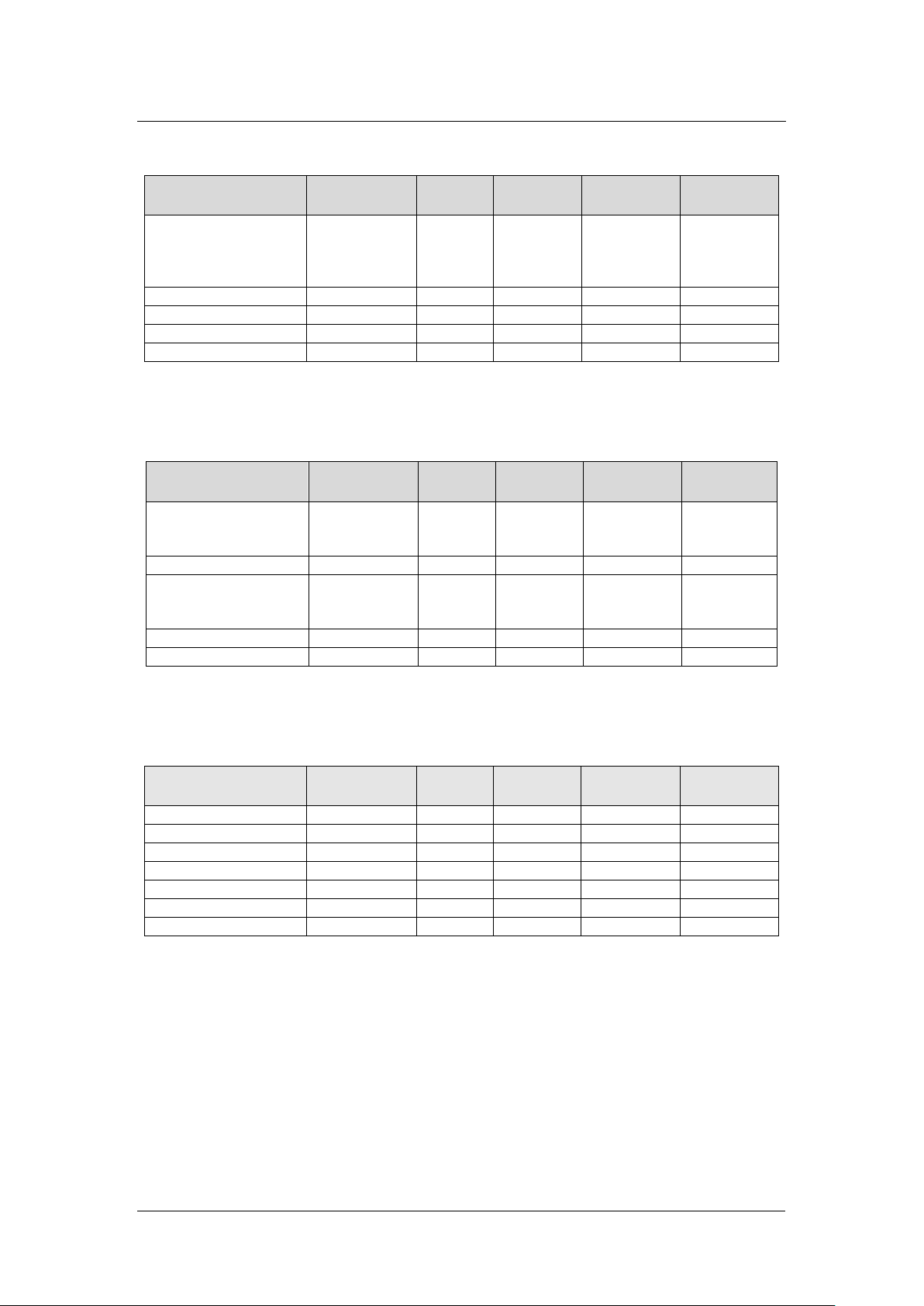
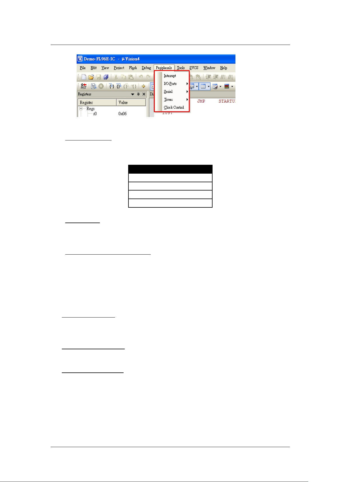
3.5 View Memory Content
Memory
Size
Memory
Type
Start
Address
End
Address
Example
Program Flash
Up to 2000B
code
0x0000
0x07CF
C:0x00000
EEPROM
16 bytes
xdata
0x100
0x10F
X:0x0100
Internal SRAM
64 bytes
idata
0x00
0x3F
I:0x00
SFR
128 bytes
data
0x80
0xFF
D:0x80
XFR
256 bytes
xdata
0x00
0xFF
X:0x0000
Memory
Size
Memory
Type
Start
Address
End
Address
Example
Program Flash
FL16B
FL32B
Up to 12KB
Up to 24KB
code
code
0x0000
0x0000
0x2FFF
0x5FFF
C:0x0000
C:0x0000
Data Flash
FL16B
FL32B
4KB
8KB
code
code
0x6000
0x6000
0x6FFF
0x7FFF
C:0x6FFF
C:0x6000
Internal SRAM
256 bytes
idata
0x00
0xFF
I:0x00
Expanded SRAM
2KB
xdata
0x0200
0x09FF
X:0x0200
SFR
128 bytes
data
0x80
0xFF
D:0x80
XFR
256 bytes
xdata
0x00
0xFF
X:0x0000
Memory
Size
Memory
Type
Start
Address
End
Address
Example
Program/Data Flash
FL32T
FLX/FL64T
FLE/FL96T
FL96TE
Up to 31KB
Up to 64KB
Up to 95KB
Up to 95KB
code
0x0000
0x7BFF
0xFFFF
0x17BFF
0x17BFF
C:0x0000
Internal SRAM
256 bytes
idata
0x00
0xFF
I:0x00
Expanded SRAM
FLX/FLE
FL32T
FL64T/FL96T
FL96TE
2KB
1.5KB
3KB
3KB
xdata
0x0200
0x0200
0x8200
0x8200
0x09FF
0x07FF
0x8DFF
0x8DFF
X:0x0200
X:0x0200
X:0x8200
X:0x8200
SFR
128 bytes
data
0x80
0xFF
D:0x80
XFR
256 bytes
xdata
0x00
0xFF
X:0x0000
3.5.1 DC6688F2SER/F2STR
3.5.2 DC6688FLB
DCT-EDP Rev3.x User Manual
.
Rev1.3
3.5.3 DC6688FLX/FLE/FLT/FL96TE
Page 14
Dragonchip
We bring silicon to life
DragonFLASHTM
14 of 27
3.5.4 DC6688FSB/FSX/FSE/FST
Memory
Size
Memory
Type
Start
Address
End
Address
Example
Program Flash
FSB
FST
FSX/FSE
Up to 30KB
Up to 29.5KB
Up to 62KB
code
0x0000
0x77FF
0x75FF
0xF7FF
C:0x0000
EEPROM
64 bytes
xdata
0x100
0x13F
X:0x0100
Internal SRAM
256 bytes
idata
0x00
0xFF
I:0x00
SFR
128 bytes
data
0x80
0xFF
D:0x80
XFR
256 bytes
xdata
0x00
0xFF
X:0x0000
Memory
Size
Memory
Type
Start
Address
End
Address
Example
Program/Data Flash
BT32
BT96
Up to 31KB
Up to 95KB
code
0x0000
0x7BFF
0x17BFF
C:0x0000
Internal SRAM
256 bytes
idata
0x00
0xFF
I:0x00
Expanded SRAM
BT32
BT96
1.5KB
3KB
xdata
0x0200
0x8200
0x07FF
0x8DFF
X:0x0200
X:0x8200
SFR
128 bytes
data
0x80
0xFF
D:0x80
XFR
256 bytes
xdata
0x00
0xFF
X:0x0000
Memory
Size
Memory
Type
Start
Address
End
Address
Example
Program/ Data Flash
Up to 31KB
code
0x00000
0x7BFF
C:0x00000
Internal SRAM
256 bytes
idata
0x00
0xFF
I:0x00
Expanded SRAM
1KB
xdata
0x0200
0x05FF
X:0x0200
1.5KB
xdata
0x0200
0x07FF
X:0x0200
2KB
xdata
0x0200
0x09FF
X:0x0200
SFR
128 bytes
data
0x80
0xFF
D:0x80
XFR
256 bytes
xdata
0x00
0xFF
X:0x0000
3.5.5 DC6688BT
DCT-EDP Rev3.x User Manual
.
Rev1.3
3.5.6 DC6288FT
3.6 Supplementary Information
3.6.1 Limitation
A) Keil IDE
Page 15
DCT-EDP Rev3.x User Manual
Dragonchip
We bring silicon to life
DragonFLASHTM
15 of 27
Items
VDD/V
DC6288
3.3
DC6388
3.3
DC6688
3.3
DC6688FL32TC
1.8
DragonICE does not support the following features.
B) Hardware
1) Voltage Supply
甲、The VDD of Debug port is fixed at specified voltage listed below. User
should only do emulation at this voltage level.
.
Rev1.3
2) Peripherals
甲、When the emulator is stopped in debugging platform, all the running
peripherals (e.g. timer 2) will still keep running. Hence, the
peripherals will be out of synchronization with the code instruction.
3) Counter A in one shot mode
甲、In one shot mode (CAM = 0), this bit have to reset to 0 every time
before setting CAS = 1.
3.6.2 Troubeshooting
1) Driver Installation
After installing the DragonICE driver, plug the emulator to PC, the driver will
be installed automatically for port connected. In case the PC fails to locate
the driver, select the driver path “C:\WINDOWS\system32” manually.
2) Upgrade Keil Project
When uv2/ uv3 projects are closed, user can choose to upgrade the project
to an uv4 project (*.uvproj).
3) Complie Keil Project
Always compile the code before entering the Keil debugging environment.
Otherwise the emulated flash content may not be updated and the debug
action may not match with the displayed code.
For example,
a) Cursor jumped to a wrong code location in debugger.
b) ‘Step’ instruction wrong executed as ‘Free Run’ instruction.
Page 16

DCT-EDP Rev3.x User Manual
Dragonchip
We bring silicon to life
DragonFLASHTM
16 of 27
4 Programming
4.1 Software Installation
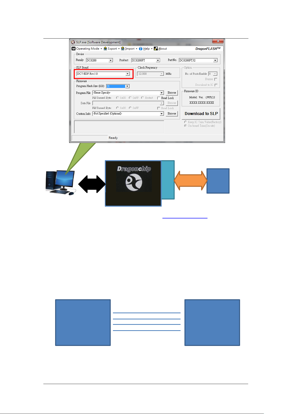
Software SLP is required on PC to control the hardware. Detail refers to
section 3.4.
4.2 Hardware setup
.
Rev1.3
Programming port provides SL interface to IC. Software SLP will automatically
select this programming port to download firmware to IC.
During debug, this port is disabled automatically.
Warning: Keil IDE must exit debugger mode before using this port via Software
SLP.
Page 17
DCT-EDP Rev3.x User Manual
Dragonchip
We bring silicon to life
DragonFLASHTM
17 of 27
Programming
P/N: DCT-EDP Rev3.0
USB
SL
VDD
ISPSEL
VSS
XIN
DC6688FSX
PCB
DCT-EDP
.
Rev1.3
IC
Detail of Software SLP operation can refer to SLP user manual.
4.3 DC6688FSX
The 4-pin connection to the DCT-EDP’s programming port from chip is shown
below. 3-pin connection is not supported.
VDD
SL
VSS
CLK1
Page 18
DCT-EDP Rev3.x User Manual
Dragonchip
We bring silicon to life
DragonFLASHTM
18 of 27
PD2 1
VSS 2
XOUT 3
XIN 4
ISPSEL 5
PA0 6
MISO/PA1 7
PA2 8
PA3 9
PA4 10
PA5 11
PA6 12
PA7 13
PC4 14
28 PC3
27 VDD
26 PC2/T2
25 PC1/REM/T1
24 PC0/T0/ISPSS
23 PB7
22 PB6/T2EX
21 PB5
20 PB4
19 PB3/TXD1
18 PB2/RXD1
17 PB1/TXD0/MOSI
16 PB0/RXD0/ISPSCK
15 PC5
Rev1.3
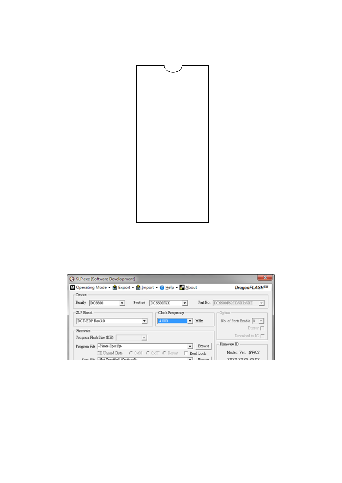
4MHz of clock frequency on Software SLP below must be selected if the board
resonator is 12MHz.
.
4.4 DC6688FST/FLT/BT
To do trimming during programming stage, 6 pads are required on PCB to
complete this process.
Page 19

DCT-EDP Rev3.x User Manual
Dragonchip
We bring silicon to life
DragonFLASHTM
19 of 27
VDD
SL/PD0
VSS
PROG
ECLK/PD1
PB6
DC6688FL32TC /
PCB
VDD
CLK2
DCT-EDP
ECLK
DC6688FL32TH6
CLK1
DCT-EDP
.
Rev1.3
FL32T / FL64T /
FL96T / FST / BT
SL
VSS
PROG
CLK1
VDD
SL
VSS
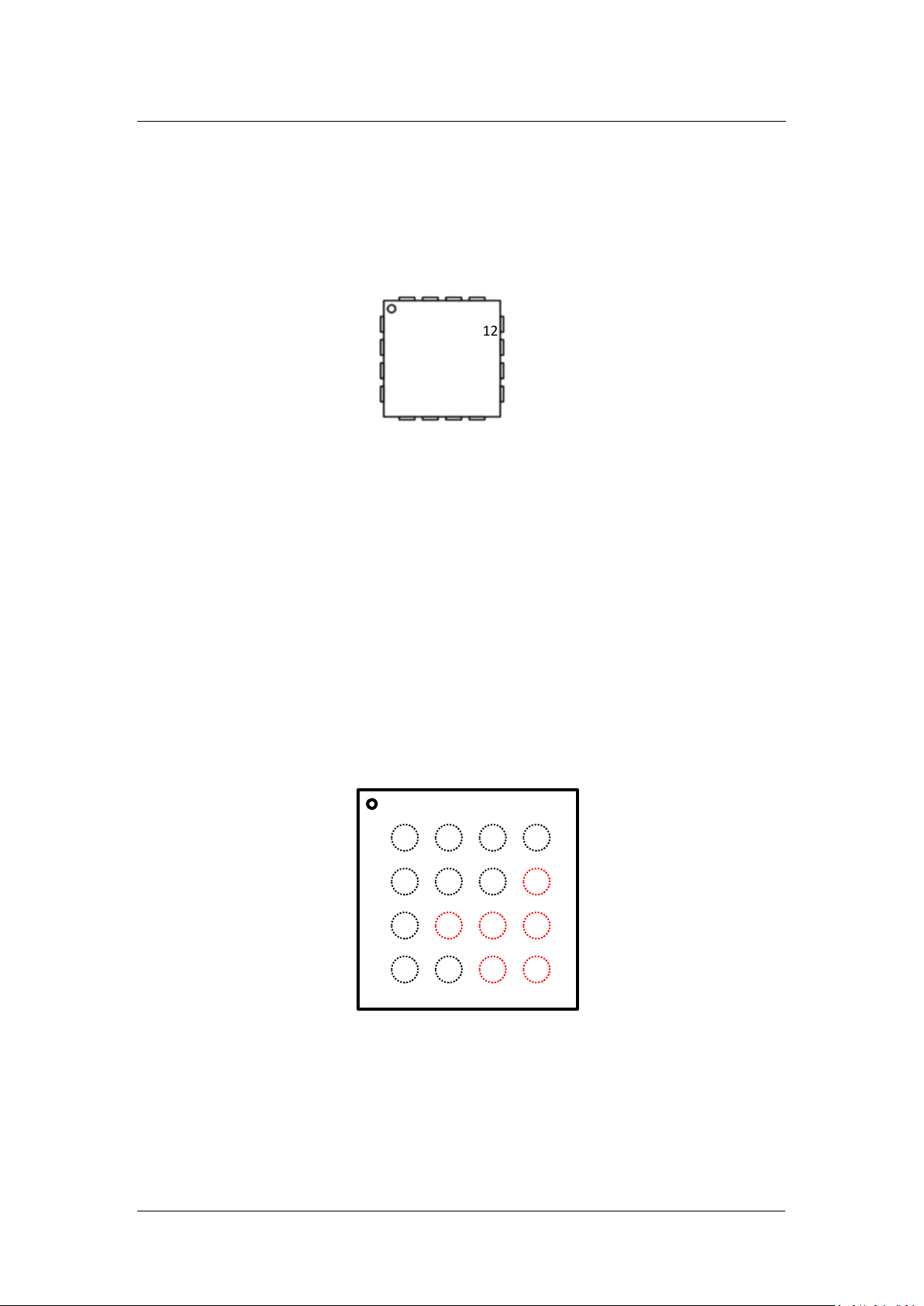
DC6688FL32TH6 only requires 4 pads.
DC6688FL32TH6 (QFN16)
VDD
SL
VSS
Page 20
Dragonchip
We bring silicon to life
DragonFLASHTM
20 of 27
12 PB1/INTB/SDA0
VSS 1
PB3/INTB/SL 2
16 IRI/IRTX/PC1
PA0/INTA/T2EX/T24EX
5
6
7
8
PB0
PB4
PB5
RST
N
IRI
PB1
PC2
VDD
PC1
VSS
PB6
PRO
G
PC0
PA1
PD0
PD1
A
B
C
D
1 2 3 4
Top View
PB4/INTB/ECLK 3
RSTN 4
DCT-EDP Rev3.x User Manual
15 VDD_IR
14 VDD
13 PB2/INTB/REM
11 PB0/INTB/SCL0
10 PA5/INTA/TXD0/SDO/PWM0
9 PA4/INTA/RXD0/SDI
.
Rev1.3
DC6688FL32TC
PA1/INTA/SCK/T2
PA2/INTA/SCL1/T1
PA3/INTA/SDA1/T0/PWM1
Page 21

Dragonchip
We bring silicon to life
DragonFLASHTM
21 of 27
DC6688FL32TT / FL96TT
IRI 1
28 PC3/INTC
VSS 1
PA7/INTA 10
20 VDD
19 PC1/INTC/REM/IRTX/T1/T24_OUT/IRI
DCT-EDP Rev3.x User Manual
.
Rev1.3
VSS 2
ECLK/PD1 3
SL/PD0 4
PROG 5
PA0/INTA 6
PA1/INTA/MISO 7
PA2/INTA 8
PA3/INTA 9
PA4/INTA 10
PA5/INTA 11
PA6/INTA 12
PA7/INTA 13
PC4 14
DC6688FL32TH / FL64TH / FL96TH
27 VDD
26 PC2/T2
25 PC1/REM/T1
24 PC0/T0/ISPSS/SCL
23 PB7/INTB/SDA
22 PB6/INTB/T2EX
21 PB5/INTB
20 PB4/INTB/SCK
19 PB3/INTB/TXD1/SDO
18 PB2/INTB/RXD1/SDI
17 PB1/INTB/TXD0/MOSI
16 PB0/INTB/RXD0/ISPSCK
15 PC5
PD1/INTD/ECLK 2
PD0/INTD/SL 3
PROG 4
PA0/INTA 5
PA1/INTA/MISO 6
PA4/INTA 7
PA5/INTA 8
PA6/INTA 9
18 PB7/INTB/T0/ISPSS
17 PB6/INTB/T2EX/T24EX/PWM1/TRIM
16 PB5/INTB/PWM0/SDA1
15 PB4/INTB/SCK/SCL1
14 PB3/INTB/SDO
13 PB2/INTB/SDI
12 PB1/INTB/TXD0/MOSI
11 PB0/INTB/RXD0/ISPSCK
Page 22

Dragonchip
We bring silicon to life
DragonFLASHTM
22 of 27
DC6688FST
VSS 1
24 VDD
PB0 1
PB1 2
PB4 3
PB5 4
5
PC0 6
PC1 7
8
24 PA4
17 PROG
32
31
30
29
28
27
26
25
9
10
11
12
13
14
15
16
VSS
RSTN
PC2
IRI
VDD1
VSS
ECLK/PD1
SL/PD0
Reserve
Reserve
Reserve
PA5
PB5
(QFN32)
(Top view)
DCT-EDP Rev3.x User Manual
.
Rev1.3
ECLK/PD1 2
SL/PD0 3
PROG 4
PA0/INTA 5
PA1/INTA/MISO 6
PA2/INTA 7
PA3/INTA 8
PA4/INTA 9
PA5/INTA 10
PA6/INTA 11
PA7/INTA 12
DC6688BT32UL
23 PC2/T2
22 PC1/REM/T1
21 PC0/T0/ISPSS/SCL
20 PB7/INTB/SDA
19 PB6/INTB/T2EX
18 PB5/INTB
17 PB4/INTB/SCK
16 PB3/INTB/TXD1/SDO
15 PB2/INTB/RXD1/SDI
14 PB1/INTB/TXD0/MOSI
13 PB0/INTB/RXD0/ISPSCK
CAP
VSS
XTAL2
XTAL1
PB6
VDD2
VSS
23 VDD3
22 RF
21 PA3
20 RA2
19 PA1
18 Reserve
Page 23
Dragonchip
We bring silicon to life
DragonFLASHTM
23 of 27
DC6688BT96UZ
PC2
RSTN
VDD
PC3
PD3
PD2
PD4
IRI
VSS
ECLK/PD1
XOUT
XIN
SL/PD0
Reserve
42 VSS
29 DTM1
56
55
54
53
52
51
50
49
48
47
46
45
44
43
15
16
17
18
19
20
21
22
23
24
25
26
27
28
PROG
PA0
PA1
PA2
PA3
Reserve
PA4
PA5
Reserve
Reserve
Reserve
Reserve
VSS
DTM0
PC1
Reserve
Reserve
(QFN56)
(Top view)
1
2
3
4
5
6
7
8
9
10
11
12
13
14
ECLK
DC6288FT
CLK1
DCT-EDP
DCT-EDP Rev3.x User Manual
.
Rev1.3
PC0
PB7
PB6
PB5
PB4
PB3
VSS
PB2
PB1
PB0
CC0
CAP
41 CC0
40 VSS
39 XTAL2
38 XTAL1
37 VDD
36 VSS
35 RF
34 VSS
33 Reserve
32 VDD
31 Reserve
30 Reserve
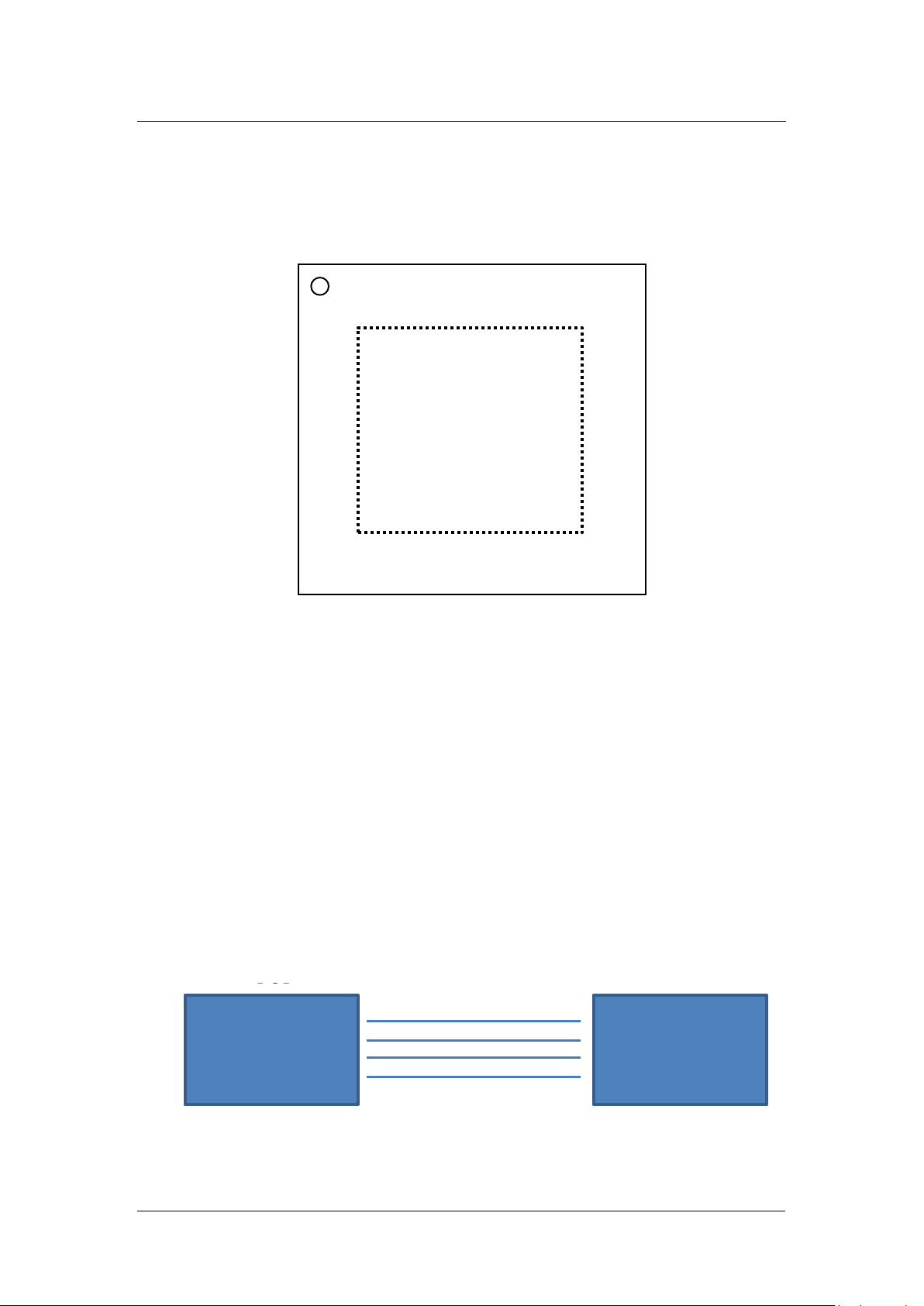
4.5 DC6288FT
To do trimming during programming stage, 4 pads are required on PCB to
complete this process.
VDD
SL
VSS
VDD
SL
VSS
Page 24

Dragonchip
We bring silicon to life
DragonFLASHTM
24 of 27
TSSOP20-M
T24_CA/PWM0/PB4
TX0/PB5
RX0/PB6
/RSTN
PC2
REM/PC1
PWM1/PC0
T24_EX/T24_CC/T0/PA0
20 PB3/T24_CB
10
PWM1/PC0
T24_CB/PB3
T24_CA/PWM0/PB4
PB5
/RSTN
PC3
PC2
REM/PC1
20 PB2
10
ECLK/RSTN
PC2
PC1
PC0
6
10
VDD
PA0
PA1
PA2
PA3
(QFN20)
(Top view)
1
5
PB1/SL
PA4
15
14
13
12
11
20
19
18
17
16
PB6
PB5
PB4
PB3
PB2
DCT-EDP Rev3.x User Manual
.
Rev1.3
TSSOP20-R
ECLK
VSS
VDD
ECLK
VSS
VDD
1
2
3
4
5
6
7
8
9
19 PB2
18 PB1/T1/SL
17 PA7/SCK/T2_CC2
16 PA6/SDI/T2_CC1
15 PA5/SDO/T24_OUT
14 PA4/T2_CC4/MCLK
13 PA3/T2_CC3
12 PA2/SCK/T2/CNVSTR
11 PA1/SDA/T2EX
1
2
3
4
5
6
7
8
9
19 PB1/T1/SL
18 PB0
17 PA7/SCK/T2_CC2
16 PA6/SDI/T2_CC1
15 PA5/SDO/T24_OUT
14 PA4/T2_CC4/MCLK
13 PA3/T2_CC3
12 PA2/SCK/T2/CNVSTR
11 PA1/SDA/T2EX
PA7
PA6
PA5
VSS
2
3
4
VSS
7
8
9
Page 25

DCT-EDP Rev3.x User Manual
Dragonchip
We bring silicon to life
DragonFLASHTM
25 of 27
ECLK/RSTN
PC3
PC2
PC1
PC0
7
10
11
12
VDD
PA0
PA1
PA2
PA3
PA4
(QFN24)
(Top view)
1
PB1/SL
PA5
18
17
16
15
14
13
24
23
22
21
20
19
PB7
PB6
PB5
PB4
PB3
PB2
Rev1.3
.
VSS
2
3
4
5
6
VSS
8
9
PB0
PA7
PA6
PC4
Page 26

Dragonchip
We bring silicon to life
DragonFLASHTM
26 of 27
Revision History
Document
Rev. No.
Issued
Date
Section
Page
Description
Edited By
Reviewed
By
1.0
May,
2019
All - Preliminary
Danny Ho
Patrick Li
1.1
May,
2019
5 Add section 5 for programming
Danny Ho
Patrick Li
2.5 Add section for pin assignment
1.2
June,
2019
6.1 Add ‘hardware setup’
Danny Ho
Patrick Li
3 Add ‘Debug’
1.3
June,
2019
All Re-organize the content
Added section 3.3.2
Danny Ho
Patrick Li
DCT-EDP Rev3.x User Manual
.
Rev1.3
Page 27

DCT-EDP Rev3.x User Manual
Dragonchip
We bring silicon to life
DragonFLASHTM
27 of 27
Rev1.3
Copyright Notice
This specification is copyrighted by Dragonchip Ltd. No part of this
specification may be reproduced in any form or means, without the expressed
written consent Dragonchip Ltd.
Disclaimer
Dragonchip Ltd. assumes no responsibility for any errors contained herein.
Copyright by Dragonchip Ltd. All Rights Reserved.
Dragonchip Ltd.
TEL: (852) 2776-0111
FAX: (852) 2776-0996
http://www.dragonchip.com
.
 Loading...