


Cato
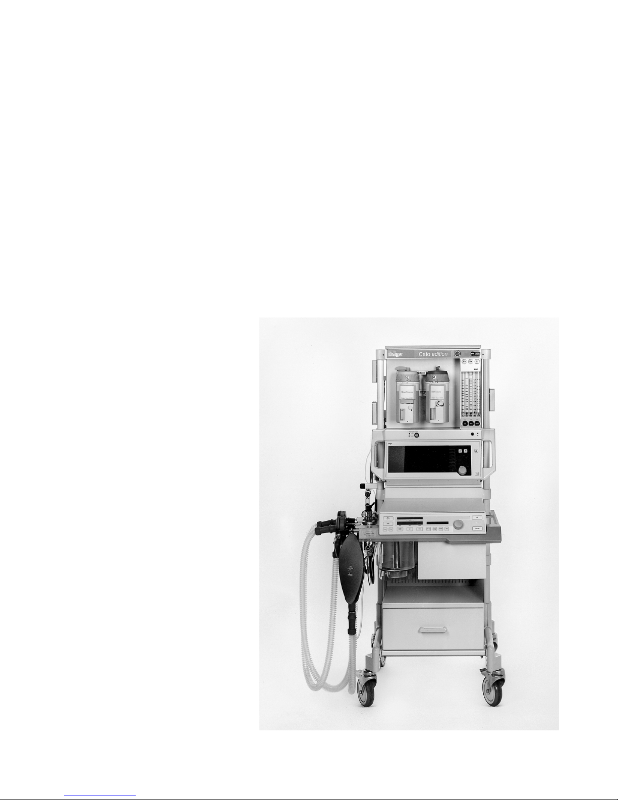
Cato edition
Anaesthetic Workstation
Instructions for Use
Software versions:
Ventilator: ...................... 7.n
Monitor: ......................... 2.n
MT-439-2000
D
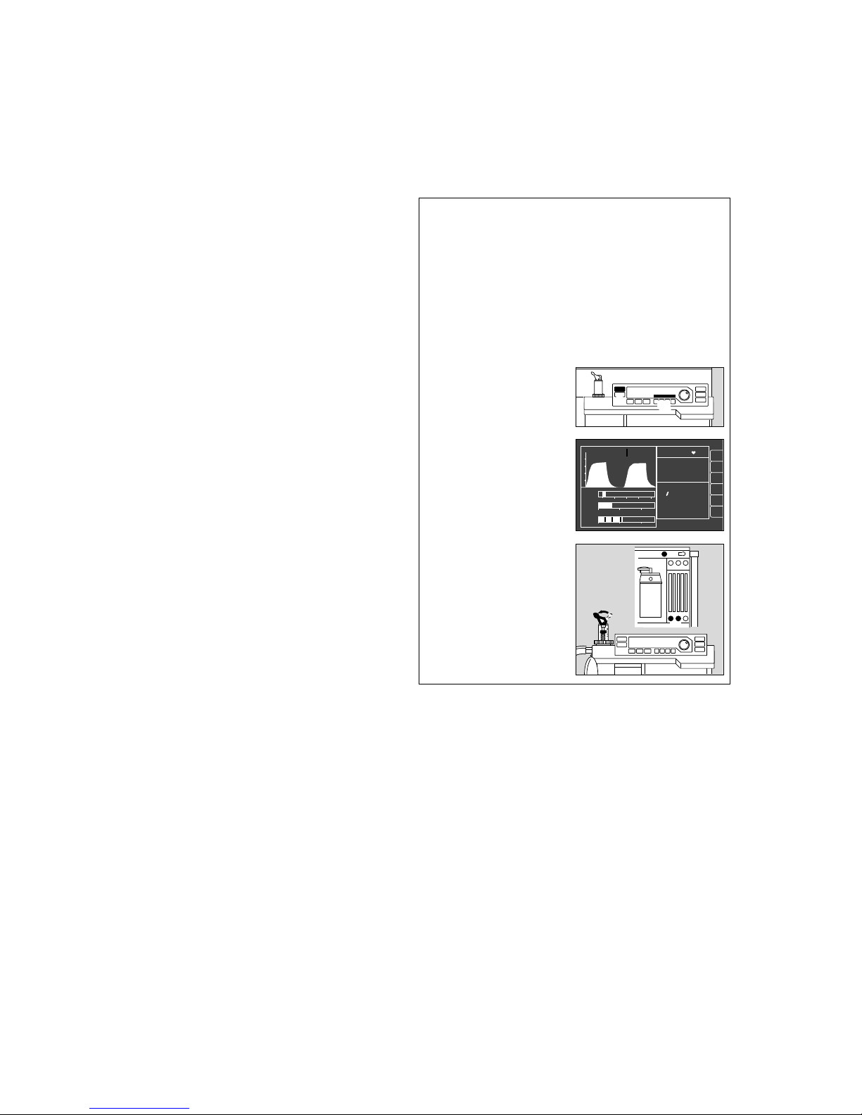
Working with these Instructions for Use
In the header line...
the subject of the main section
The sub-section title is given underneath the main title to
help you find your way rapidly through the manual.
Page body
Instructions for Use
in text-graphic combination. The information is translated
directly into physical actions that teach the user in practical steps how to use the apparatus.
Left-hand column...
the text
contains explanations and guides the user in the operation of the product with concise, clear and unmistakable
instructions in ergonomic sequence.
The bullets (dots) indicate separate steps, and, when
several steps are described, the numbers indicate details
in the illustrations and also specify the order of action.
Right-hand column...
the illustrations
provide a visual reference for the text and make it easier
to locate the various parts of the equipment. Details
mentioned in the text are highlighted. Irrelevant details are
omitted.
The user is also prompted by screen displays which
confirm the operating sequence.
Working with these Instructions for Use
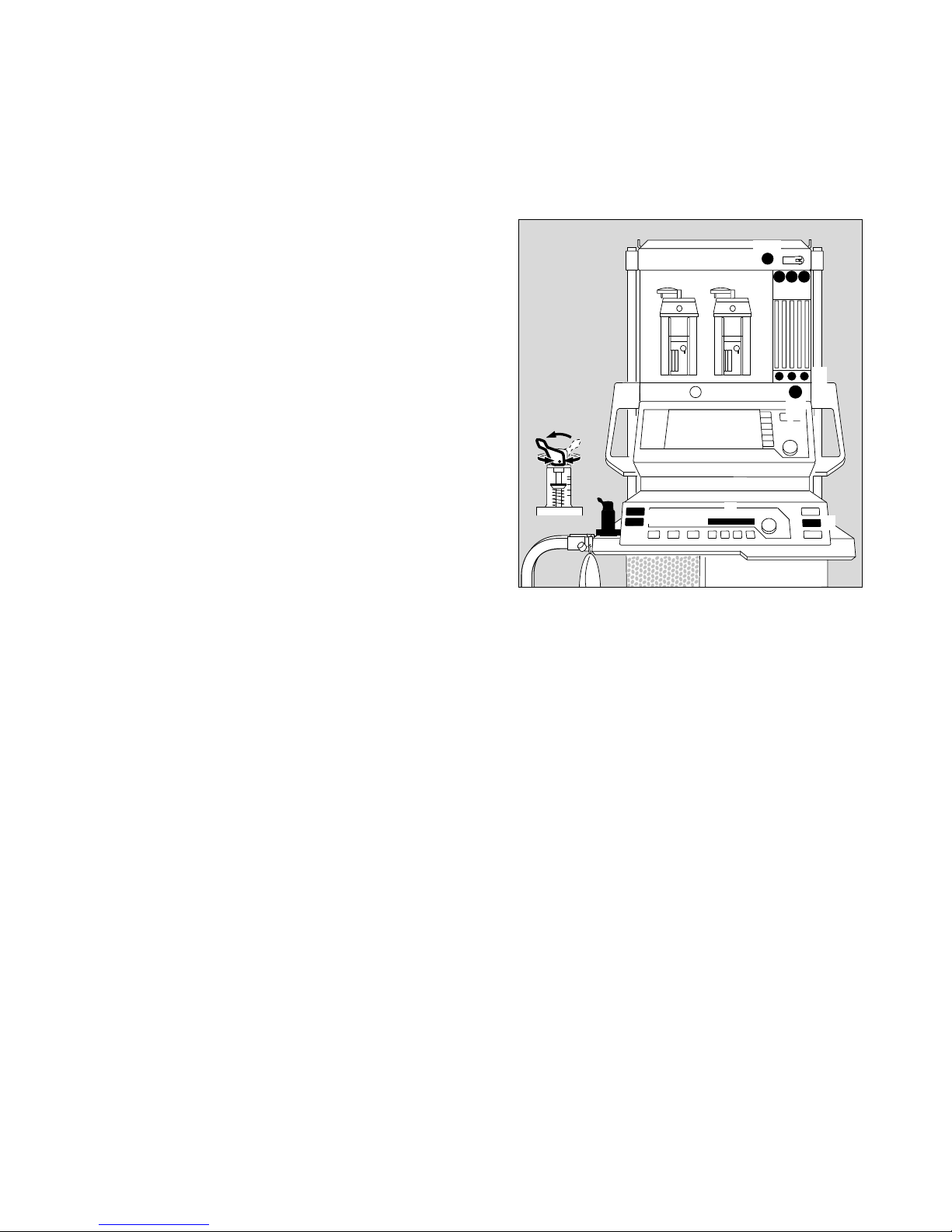
Manual / Spontaneous
Before connecting a patient
● Check workstation with checklist (see page 21).
– Check that breathing system is complete
(see page 20) and
– perform leakage test (see page 31).
Select Manual / Spontaneous mode
1 Press »MAN/SPONT« on ventilator for at least one
second –
2 Display in dialogue field:
MAN/SPONT
The standard screen appears with the alarm limits
for MAN/SPONT mode.
Spontaneous breathing
»PEEP« and pressure limitation »Pmax« are inactive.
3 Set pressure limiting valve APL to »SPONT«.
It is now open, regardless of the set pressure.
To fill system:
4 Press »O2 +« to inflate the breathing bag rapidly –
5 Set fresh gas –
detailed information on setting the fresh gas flow
can be found in the Annex on page 130.
1
2
Operation
Manual / Spontaneous
Select Manual / Spontaneous mode
Spontaneous breathing
alarm
limits
CO
2
al. off
curve
list
alarm
info
Man./spont. alarm limits
SpO2 98 67
etCO2 38
MV 6.0 freq 10
Fi Fet
O
2
29 25
Hal. 0.8 0.6
N2O 70 68
20
18
V
T
0.35
PAW
0
0
Volumeter 27s
5.5
05
10
0.5
1
Volumeter started.
Re-start: confirm !
40
20
CO
2
40
0
config
.
3
4
5
2
00128971 2402897000137224

3
Contents
Index 143
Contents
For your safety and that of your patients 4
Quick start in an emergency 7
Operating concept 9
Preparing for use 17
Operation 35
Monitor functions 49
Troubleshooting (messages - cause - remedy) 71
Care 79
Check operational readiness 101
What's what 107
Technical data 115
Descriptions 123
Intended use 5

For Your Safety and that of Your
Patients
Strictly follow the Instructions for Use
Any use of the apparatus requires full understanding and
strict observation of these instructions. The apparatus is
only to be used for purposes specified here.
Maintenance
The apparatus must be inspected and serviced regularly
by trained service personnel at six monthly intervals
(and a record kept).
Repair and general overhaul of the apparatus may only be
carried out by trained service personnel.
We recommend that a service contract be obtained with
DrägerService and that all repairs also be carried out by
them. Only authentic Dräger spare parts may be used for
maintenance.
Observe chapter "Maintenance Intervals".
Accessories
Do not use accessory parts other than those in the order
list.
Not for use in areas of explosion hazard
This apparatus is neither approved nor certified for use in
areas where combustible or explosive gas mixtures are
likely to occur.
Safe connection with other electrical equipment
Electrical connections to equipment which is not listed in
these Instructions for Use should only be made following
consultations with the respective manufacturers or an
expert.
Liability for proper function or damage
The liability for the proper function of the apparatus is
irrevocably transferred to the owner or operator to the
extent that the apparatus is serviced or repaired by
personnel not employed or authorized by DrägerService
or if the apparatus is used in a manner not conforming to
its intended use.
Dräger cannot be held responsible for damage caused
by non-compliance with the recommendations given
above. The warranty and liability provisions of the terms
of sale and delivery of Dräger are likewise not modified
by the recommendations given above.
Dräger Medizintechnik GmbH
For Your Safety and that of Your Patients
4

Intended use
Anaesthetic Workstation Cato
Universally applicable anaesthetic workstation for
● Inhalation anaesthesia in semi-closed systems
● Inhalation anaesthesia in virtually closed systems with
»low flow« and »minimal flow« techniques for minimum
gas and anaesthetic consumption, with:
● Inhalation anaesthesia in non-rebreathing systems
with separate fresh gas outlet for connecting e.g.
Kuhn system.
● Automatic ventilation (IPPV)
● Synchronized intermittent mandatory ventilation
(SIMV)
● Manual ventilation (MAN)
● Spontaneous breathing (SPONT)
The workstation must only be used under the
supervision of qualified medical staff, so that help is
available immediately if any faults or malfunctions
occur.
Explosive anaesthetic agents, such as ether or
cyclopropane, must not be used due to the risk of fire!
The equipment cannot distinguish between different
anaesthetics. Dräger cannot accept any liability if the
wrong anaesthetic is used!
Additional electric devices clipped into the top of
the unit must be connected to the base unit via an
equipotential bonding (earthing) conductor.
Do not use mobile phones within a distance of
10 metres from the machine.
Mobile phones can cause interference to electrical and
electronic medical appliances, thereby putting patients at
risk.*
Do not use Cato for nuclear spin tomography.
The functioning of the apparatus may be impaired.
Since this equipment is not approved for use with inflammable anaesthetics (ether, cyclopropane, etc.), it is not
necessary to use antistatic (conductive) breathing hoses
or face masks.
Conductive breathing hoses and face masks may cause
burns during high-frequency surgery and are therefore
not recommended for this equipment.
The workstation should be moved using the handles
only.
* Dräger medical appliances comply with the interference immunity
requirements of the specific standards for the products or
EN 60601-1-2 (IEC 601-1-2). However, depending on the design
of the mobile phone and situation of use, field strengths may occur
in the immediate environment of a mobile phone that exceed the
values of the standards quoted and therefore cause interference.
Measurement and monitoring functions:
● Measurement of the ventilation parameters:
pressure, flow, O2 concentration (inspiratory and
expiratory)
● Continuous measurement of the CO2 concentration
and N2O/anaesthetic concentration (halothane, enflurane, isoflurane, sevoflurane, desflurane). The flow
rate for sampling the measuring gas can be varied
and is returned to the circulation.
● Automatic adjustment of the alarm limits for automatic
ventilation IPPV.
● Anaesthetic vaporizer with automatic Vapor
recognition1).
Optional:
❍ Continuous non-invasive measurement of the
functional O2 saturation.
❍ Measurement of the inspiratory breathing gas
temperature.
❍ Expiratory O2 value.
The following values are indicated:
● Continuous curve for airway pressure, peak and
plateau pressure, mean pressure and PEEP.
● Patient compliance.
● Expiratory minute volume, tidal volume and respiration
rate.
● Expiratory flow curve.
● Inspiratory and expiratory O2 concentration.
● Inspiratory and expiratory concentration of N2O and
anaesthetic halothane, enflurane, isoflurane, sevoflurane and desflurane.
● Inspiratory and end-expiratory CO2 concentration
(inCO2 and etCO2).
● Continuous CO2 curve.
● List entries and trend displays.
Optional:
❍ Functional O2 saturation, pulse rate, plethysmogram.
❍ Inspiratory breathing gas temperature.
❍ Expiratory O2 value.
1) Refer to the separate Instructions for Use for the Vapor!
5
Intended use
Anaesthetic Workstation Cato

The following parameters are monitored:
● Airway pressure.
● Expiratory minute volume.
● Inspiratory O2 concentration.
● Inspiratory and expiratory CO2 concentration.
● Inspiratory anaesthetic concentration.
Optional:
❍ Functional O2 saturation and pulse.
❍ Inspiratory breathing gas temperature with invariable
upper alarm limit.
Accessories
– Patient monitoring
Optional monitor PM 8060 vitara1).
Parameter box for patient monitoring and measurement of the haemodynamic patient values.
● ECG/arrhythmia analysis.
● Pulse rate.
● Respiration.
● Invasive (2 channels) and non-invasive blood
pressure.
● Functional O2 saturation and pulse.
● Body temperature (2 channels).
– Aquapor
1)
for humidifying and heating the breathing gas.
– Secretion aspirator
1)
– Vapor
1)
Anaesthetic vaporiser for halothane, enflurane,
isoflurane and sevoflurane.
– Connection for two "Vapor" anaesthetic vaporisers
1)
– Devapor
1)
Anaesthetic vaporiser for desflurane.
– Anaesthetic gas scavenging system
1)
– Uninterruptible power supply
1)
1) Refer to the separate Instructions for Use for this equipment!
Intended use
Anaesthetic Workstation Cato
Accessories
6
Quick start in an emergency
● Plug the gas connectors into the gas supply wall
sockets.
1 The O2, AIR and N2O pressure gauges must be in
the green range.
● Plug the power plug into the mains.
2 Press the master switch.
All the LEDs on the ventilator light up.
3 Press the key for the desired operating mode on the
ventilator –
Recommendation: hold down M for longer than
1 second.
4 The following message is displayed in the display
window of the ventilator:
Test 3 x discont (example)
Number of times that the self-test has been interrupted for a quick start since it was last completed
successfully.
● Set the selector switch to »N2O« or »AIR«.
5 Deliver fresh gas.
6 Press O2 flush – if necessary –
to fill the system and the breathing bag rapidly.
7 Switch the pressure limiting valve (APL) to »MAN«.
8 Set maximum pressure. Turn the lever of the pressure
limiting valve clockwise until the indicator (plate)
stands at maximum pressure.
No more than ten consecutive quick-starts are allowed
between two complete self-tests. This maximum is only
permitted if the previous completed self-test revealed no
fault.
After the 10th consecutive quick-start, the following
message appears in the ventilator display window:
last cancel
If a further attempt is made to cancel the self-test and carry
out a quick start, the following message is displayed:
COMPLETE TEST
Quick-start not permitted.
A complete self-test must be carried out before startup is possible.
However, in all cases, manual ventilation is always
possible.
Quick-start can be started at any time, even while a selftest is in progress.
D
1
7
8
6
2
5
3
4
3
Cato edition
7
Quick start in an emergency
00237224

Power failure (manual ventilation is still possible)
● The master power switch must be pressed.
The audible power failure warning is muted after
45 seconds.
● Deliver fresh gas and set the pressure limiting valve
(APL). If necessary press the O2 Flush key (»O2 +«).
If there is a power failure, the ventilator piston is
forced back to its end position by the airway
pressure, thereby increasing the system volume
by max. 1.4 litre.
Gas failure
If AIR (medical compressed air) fails
– Cato automatically switches over to O2.
If O2 fails
– Cato automatically switches over to AIR. An audible
warning is emitted (O2 shortage warning). N2O
delivery is blocked:
If O2 and air fail:
Ventilate the patient immediately with the
separate emergency ventilation bag!
Auto-WakeUp
Manual ventilation cannot be performed in standby mode.
Any attempt to perform manual ventilation in standby
mode is detected by the system on account of the
pressure thrust in the breathing bag and it automatically
switches to »MAN/SPONT« mode in which manual
ventilation can then be performed. The background
lighting of the flow measuring tubes goes on at the same
time.
The system is protected against excess static pressures:
The system pressure is relieved automatically if an excess
static pressure of more than 30 mbar is present for more
than 60 seconds.
Dräger recommends that manual ventilation should
always be started by pressing the »MAN/SPONT« key.
8
Quick start in an emergency
Power failure
Gas failure
Auto-WakeUp
[
[

Contents
Page
Operating concept, general ................................................................... 10
Master switch for electricity supply .......................................................... 10
Operating concept of the ventilator ...................................................... 11
Keys with dedicated function ................................................................... 11
Display window without dialogue function ................................................ 12
Display window with dialogue function .................................................... 12
Operating concept of the monitor ......................................................... 13
Keys with dedicated function ................................................................... 13
Displays .................................................................................................. 13
Measured values with grey numerals ....................................................... 13
Screen structure ..................................................................................... 14
Screen saver ........................................................................................... 14
Rotary control.......................................................................................... 14
The various screen displays .................................................................... 16
9
Operating concept
Contents
Operating concept
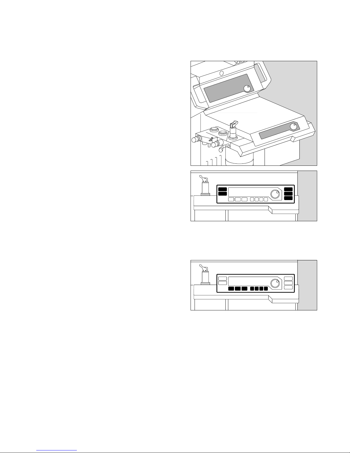
Operating concept, general
Master switch for electricity supply
Master switch
1 Press to switch on
Dialogue:
Monitor and ventilator feature a dialogue with the user
mediated by:
● keys,
● rotary controls,
● displays and
● beeps.
Basic conditions of the operating state are
established by adjusting the delivery valves
or pressure limitation (e.g. APL valve).
● Keys: For direct command input
● Rotary control:
For selection by ...
... turning
This causes a cursor frame (on the screen)
to be moved or a variable numerical value
(on the display window of the ventilator or
on the screen) to be changed.
... pressing
The value selected with the rotary control
is adopted as a valid parameter or a
process is started or ended.
● Displays: For presenting all information on the
screen and on the display windows of the
ventilator.
● Tone sequences:
As an acoustic supplement to the
messages. They are coupled with certain
sounds or tone sequences, according to
priority classes.
Tone sequences accompanying warnings
are output continuously, every 30 seconds
with caution messages and only once in
conjunction with advisory messages.
These are to draw the user's attention to
the messages which appear simultaneously in the displays.
European Standard EN 740 stipulates use
of EN tones.
Alternatively there are tones in keeping
with Dräger conventions available.
1
Operating concept
Operating concept, general
Master switch for electricity supply
10
IPPV
MAN
SPONT
003372242432897000328970
Operating concept of the ventilator
Keys with dedicated function –
for setting the operating modes
Left-hand side:
Key for manual ventilation or
spontaneous breathing.
Key for IPPV mode.
Right-hand side:
Key for leakage test and compliance
measurement.
Key for SIMV mode.
Standby key.
for setting ventilation parameters
Below the display window:
Key for setting the maximum pressure
for IPPV and SIMV ventilation.
Key for setting the tidal volume.
Key for setting the ventilation frequency
in IPPV mode.
Key for setting the time ratio between
inspiration and expiration.
Key for setting the relative inspiratory
pause.
Key for setting the PEEP pressure for
IPPV mode.
Key for setting the ventilation frequency
in SIMV mode.
11
Operating concept
Operating concept of the ventilator
Keys with dedicated function
M
I
T
S
A
p
B
F
t
†
P
f
G
A
S
004372240052897000628970
Operating concept
Operating concept of the ventilator
Display window without and with dialogue function
12
Display window without dialogue function
Top left:
Continuous indication of the relative piston movement
(in % referred to the set stroke volume VT)
The set operating parameters correspond with the keys
below:
– Indication of the maximum pressure Pmax in mbar.
– Indication of the tidal volume VT in mL or L.
– Indication of the ventilation frequency fIPPV in breaths
per minute.
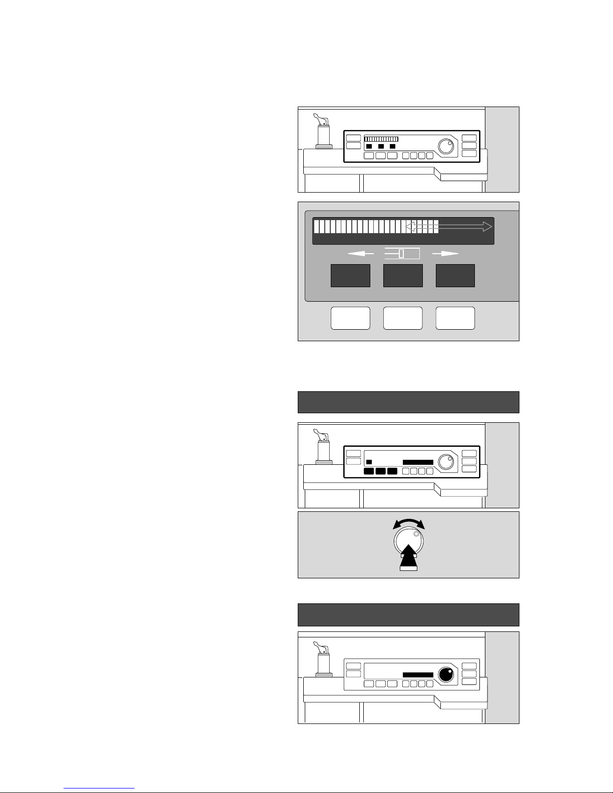
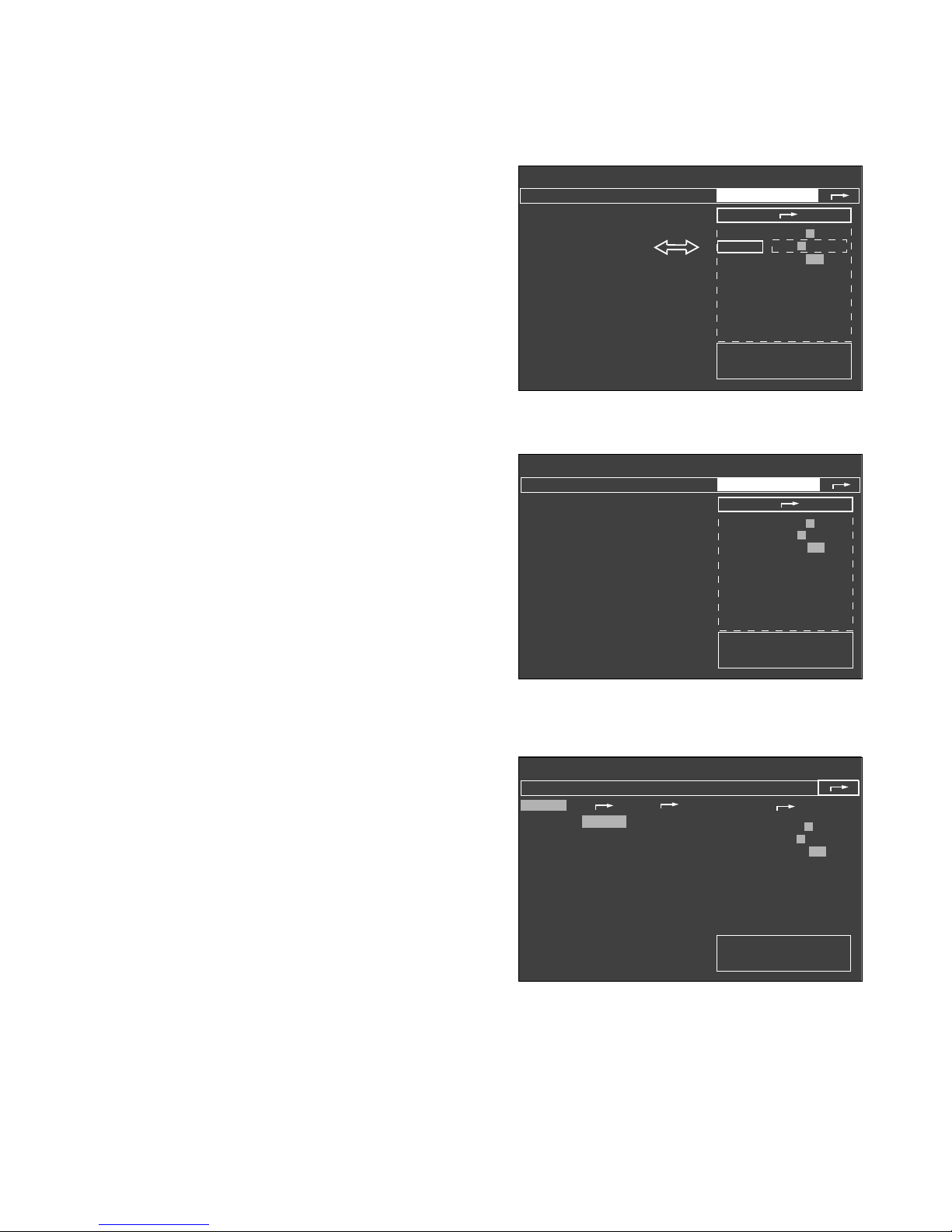
Display window with dialogue function
(in combination with the rotary control)
Example: adjusting the maximum pressure
In the black field, beside the rotary control:
1 The set value appears on the right and left-hand sides
of the field when a parameter key (Pmax, VT, fIPPV) is
pressed. Here: »23«.
2 The value on the right-hand side is changed by turning
the rotary control. Here: »28«.
The old and new values are consequently always
displayed together.
3 The value on the right («28«) is confirmed as the
definitive value by pressing the control.
If the rotary control is not pressed and not turned again,
the machine is reset after 10 seconds without changing
the setting.
● This dialogue window also displays advisory messages
(see page 78) –
Example: »Paed. hoses !«:
23 Pmax / mbar 28
Paed. hoses !
2
3
1
0% 100%
Pmax
23
VT
600
fIPPV
12
mbar ml/L 1/min
0072897000828970009289700102897001128970
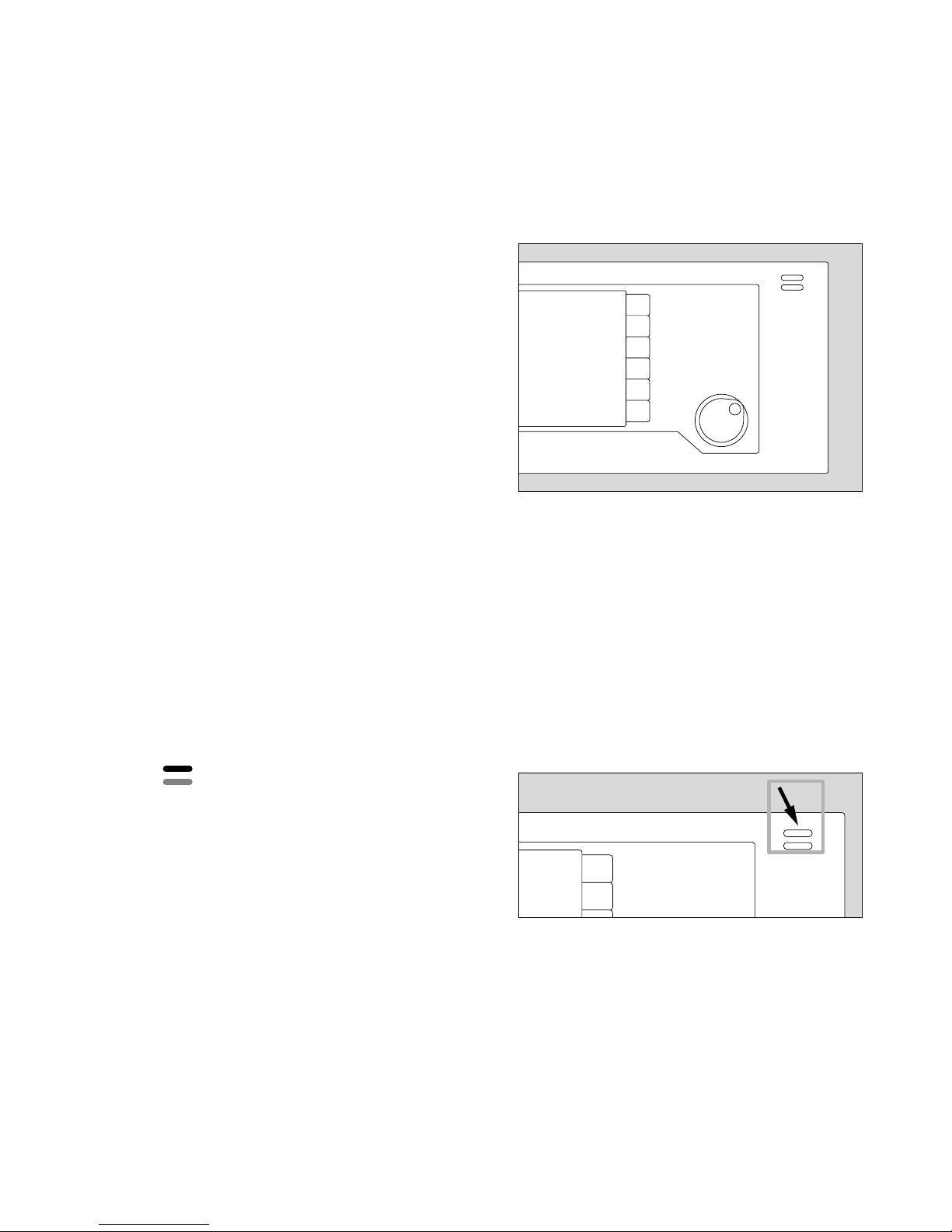
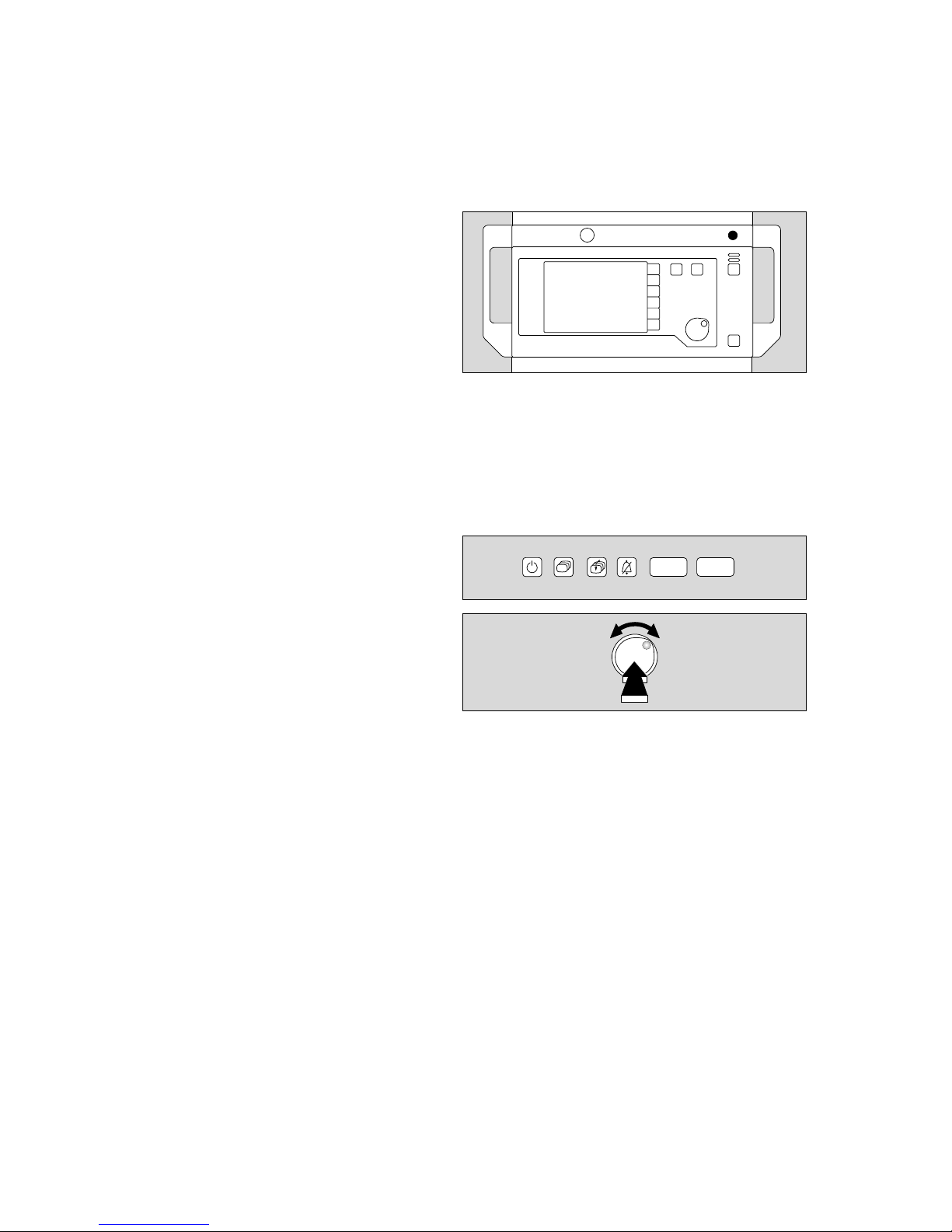
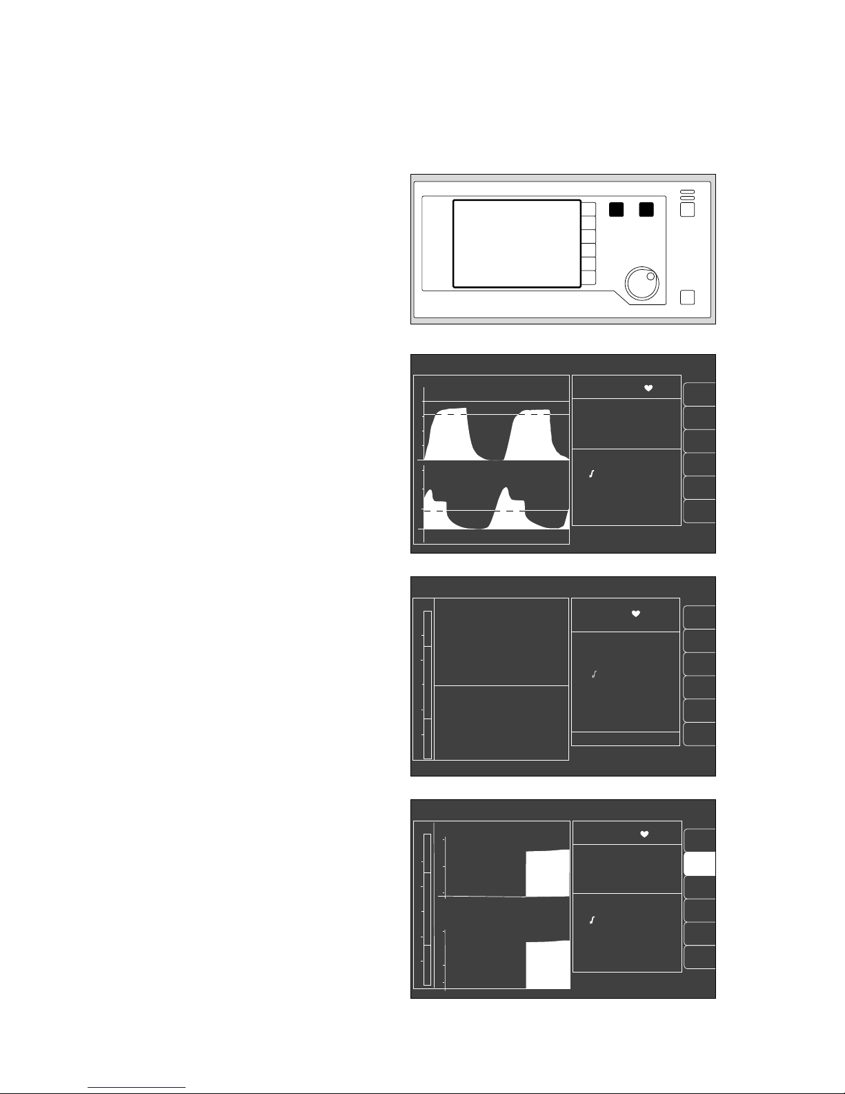
Operating concept of the monitor
Keys with dedicated function (Hardkeys)
The right-hand side is reserved for operating elements,
the left-hand side for displays.
This key switches the monitor from standby to
measuring mode and vice versa.
The monitor mode depends on the ventilator
mode:
Standby can only be selected on the monitor if
the ventilator is also in standby.
The monitor starts up when the ventilator is
started.
This key is used to deactivate the alarm tone for
two minutes. It is reactivated by pressing the key
again. The yellow LED in the key lights up while
alarms are suppressed.
Inside the dark area, there are two keys acting directly on
the screen contents:
This key is used to switch directly from one
screen to the next in succession.
This key is always used to call up the »Standard
screen« (see page 57).
Displays
Two bar-shaped indicator lamps are located above
the G key: these lamps continue to indicate the
alarm states even when the acoustic alam is
switched off.
Red (upper) lamp, flashing: Warning !!!
Yellow (lower) lamp, flashing: Caution !!
Yellow lamp, constant: Advisory !
Measured values with grey numerals
Measured values generated by an uncalibrated sensor
are shown in grey type. This may be due to the following
causes:
– Self-test has been aborted.
– Automatic sensor calibration is in progress.
– The measuring equipment for the anaesthetic gas
composition has not yet reached the required working
temperature when the system is started.
13
Operating concept
Operating concept of the monitor
Keys with dedicated function, Displays
Measured values with grey numerals
E
G
W
Q
E
G
QW
G
QW
01228970
00537224
01428970
Operating concept
Operating concept of the monitor
Screen structure, Screen saver
Rotary control
14
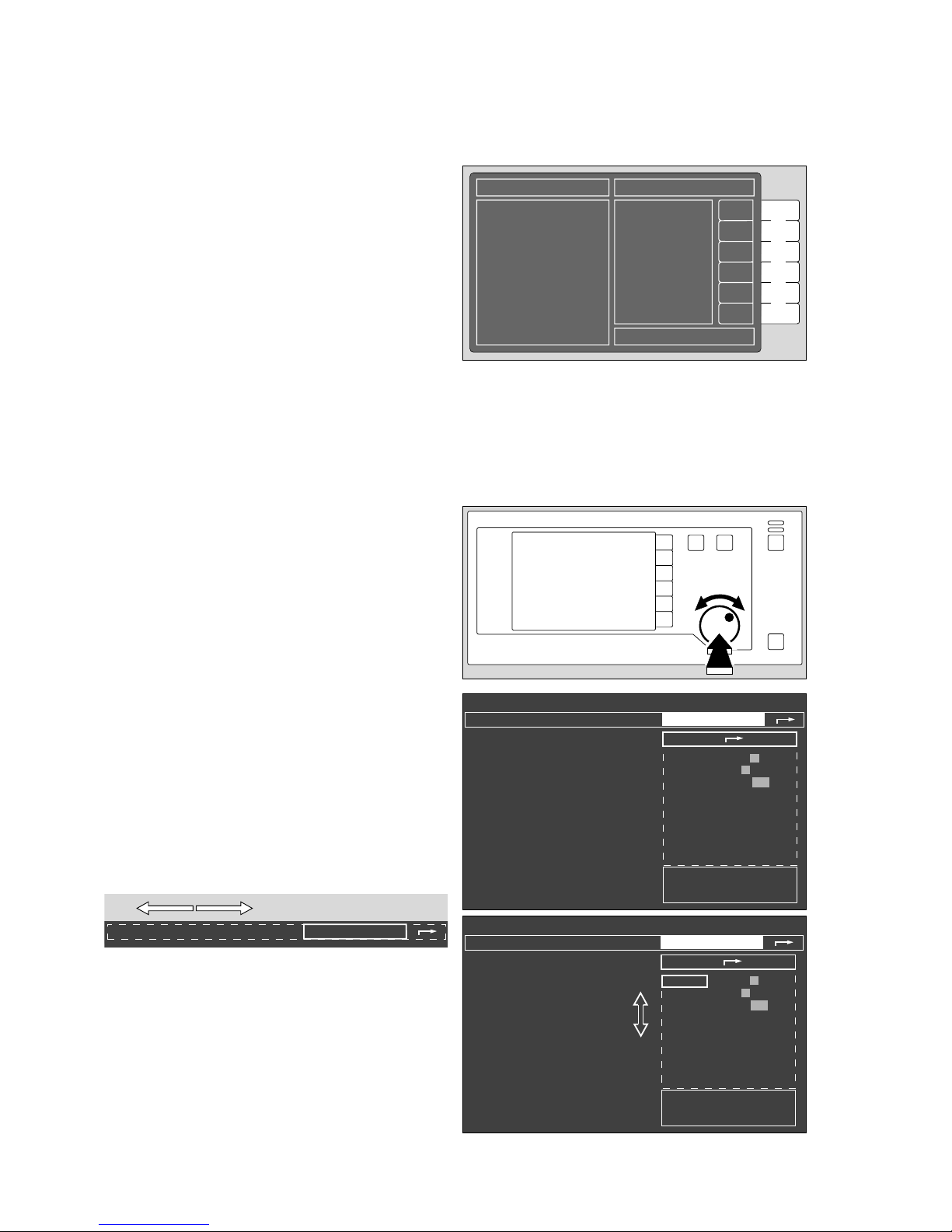
Screen structure
● Status field top:
contains information on the current alarm mode
of the monitor.
● Alarm field top:
indicates any alarms and their priority.
● Graphic field left:
for curves and bar graphs.
● Measured value field right:
for the most important numerical values.
● Operator prompts bottom right:
prompts to guide the operator.
● Softkeys right:
for rapid selection of the functions displayed on the
screen.
Screen saver
If none of the operating elements on the monitor is
operated in »standby« for approx. 2 minutes, the screen
switches off and becomes dark. The yellow LED in the
standby key and the word »standby« on the ventilator
light up. The monitor display is immediately restored as
soon as any key is pressed.
Rotary control
Selection and adjustment with a single control.
For example:
Adjusting the volume of the pulse tone
after calling up the menu of default values via the softkey
»config.« in standby (after entering a code).
● Turn rotary control = selection.
The cursor frame moves horizontally in the dashed
area.
● Press rotary control = confirm selection.
The selection is confirmed and appears in dark type
on a light background. The cursor frame is positioned
over the arrow symbol ( z) to the next higher menu.
● Turn rotary control = the cursor frame moves vertically
inside the dashed area.
Select pulse tone.
anaesth. gas
warning calibrating
defaults
Standby / Configuration
Alarms inactive!
anaesth. gas
warning calibrating
defaults
pulse tone
0 1 2 3 4 5 6 7 8 9
alarm tone 1 2 3 4 5 6 7 8 9
mode adult Neo.
parameters
record
interfaces
alarm limits
curves
basic configuration
Standby / Configuration
Alarms inactive!
anaesth. gas
warning calibrating
defaults
pulse tone
0 1 2 3 4 5 6 7 8 9
alarm tone 1 2 3 4 5 6 7 8 9
mode adult Neo.
parameters
record
interfaces
alarm limits
curves
basic configuration
Menu for setting
pulse tone volume.
Status field Alarm field
Measured
value field
Operator prompts
Graphic field
Softkeys
002289710032897100428971
00528971
01628970
● Press rotary control = confirm selection.
The selection is confirmed and appears in dark type
on a light background.
● Turn rotary control = select new setting.
● Press rotary control = confirm selection.
The cursor frame is now on the arrow symbol ( z)
to the next higher menu.
● Turn rotary control = select new setting.
Or:
● Press rotary control again = close submenu
»defaults«.
The cursor frame is on the arrow symbol ( z)
to the next higher menu.
The current configuration is indicated by the fields with
grey background.
● Press rotary control again = exit menu.
15
Operating concept
Operating concept of the monitor
Rotary control
Standby / Configuration
✓
anaesth. gas
Halothane
Enflurane
Isoflurane
Sevoflurane
Desflurane
no
anaesth. gas
warning
default
✓
calibrating
O
2
-sensor
21 Vol.%
flow sensor
Ventilator
start up test
more
✓
Alarms inactive!
defaults
pulse to.
0 1 2 3 4 5 6 7 8 9
alarm tone 1 2 3 4 5 6 7 8 9
mode adult Neo.
parameters
record
interfaces
alarm limits
curves
basic configuration
Standby / Configuration
Alarms inactive!
anaesth. gas
warning calibrating
defaults
pulse tone
0 1 2 3 4 5 6 7 8 9
alarm tone 1 2 3 4 5 6 7 8 9
mode adult Neo.
parameters
record
interfaces
alarm limits
curves
basic configuration
Menu for setting
pulse tone volume.
Standby / Configuration
Alarms inactive!
anaesth. gas
warning calibrating
defaults
pulse tone
0 1 2 3 4 5 6 7 8 9
alarm tone 1 2 3 4 5 6 7 8 9
mode adult Neo.
parameters
record
interfaces
alarm limits
curves
basic configuration
006289710072897100828971
The various screen displays
1 The three different screen displays are invoked by
pressing W.
2 Press Q to return to the standard screen from any
screen display.
The standard screen
with the CO2 curve and another selectable curve. The
most important measured values are grouped together
on the right.
The data screen
contains all measured values with their units of measure;
simplifies the completion of the anaesthesia record.
The trend screen
for displaying the changes in measured values since
measurement started.
The current measured values are shown on the right.
Operating concept
Operating concept of the monitor
The various screen displays
16
alarm
limits
auto set
vent. al.
list
IPPV alarm limits
alarm
info
10 - 03 - 97 8:00
PAW
peak 37 mbar
plat. 30
PEEP 5
mean 20
compliance 15 ml/mbar
MV 6.0 L/min
V
T
0.60 L
freq 10 1/min
AW-temp 38
o
C
20
40
0
Fi Fet
SpO
2
98 67
% 1/min
0 36
29 25
0.8 0.6
70 68
CO
2
mmHg
O
2
%
Hal.
%
N2O
%
sys-compl. 1.5 from 10-03
leakage 5 8 : 00
18
config.
alarm
limits
auto set
vent. al.
curve
list
config.
alarm
info
IPPV alarm limits
SpO
2
98 67
etCO
2
38
MV 6.0 freq 10
Fi Fet
O
2
29 25
Hal. 0.8 0.6
N
2
O 70 68
CO
2
40
0
PAW
20
0
20
18
SpO
2
pulse
AGas
N
2
O
IPPV alarm limits
CO
2
MV
O
2
compl.
SpO
2
98 67
etCO
2
38
MV 6.0 freq 10
Fi Fet
O
2
29 25
Hal. 0.8 0.6
N
2
O 70 68
18
MV
15
5
0
CO
2
60
30
0
11:00 12:00 13:00
PAW
20
40
0
10
full
trend
alarm
limits
12
009289710102897101128971 02328970

Contents
Page
Connecting the equipment .................................................................... 18
Electricity and gas supply ........................................................................ 18
Auxiliary electrical equipment ................................................................... 18
Anaesthetic gas scavenging system (AGS) ............................................. 19
Anaesthetic agent vaporiser .................................................................... 19
Uninterruptible power supply ....................................................................20
External equipment .................................................................................. 20
Checking readiness for operation with checklist .................................. 21
Vapor ...................................................................................................... 22
Anaesthetic gas scavenging .................................................................... 22
Breathing system .................................................................................... 23
Soda lime ................................................................................................ 23
Emergency ventilation bag ....................................................................... 23
Water traps ............................................................................................. 24
Reserve gas cylinders (optional) .............................................................. 24
Pipelinie gas supply ................................................................................. 24
Gas delivery ............................................................................................ 24
Oxygen Ratio Control (ORC) .................................................................. 25
O2 Flush ................................................................................................. 25
Secretion aspirator (optional) .................................................................. 25
Power supply .......................................................................................... 26
Self-test .................................................................................................. 26
Fresh gas - External outlet (optional) ........................................................ 27
Selecting anaesthetic agent ..................................................................... 28
Automatic calibration of O2/flow sensors ................................................. 29
Manual calibration of the O2 sensor ......................................................... 29
Manual calibration of the flow sensor ....................................................... 30
Ventilator start-up test ............................................................................. 31
17
Preparing for use
Contents
Preparing for use
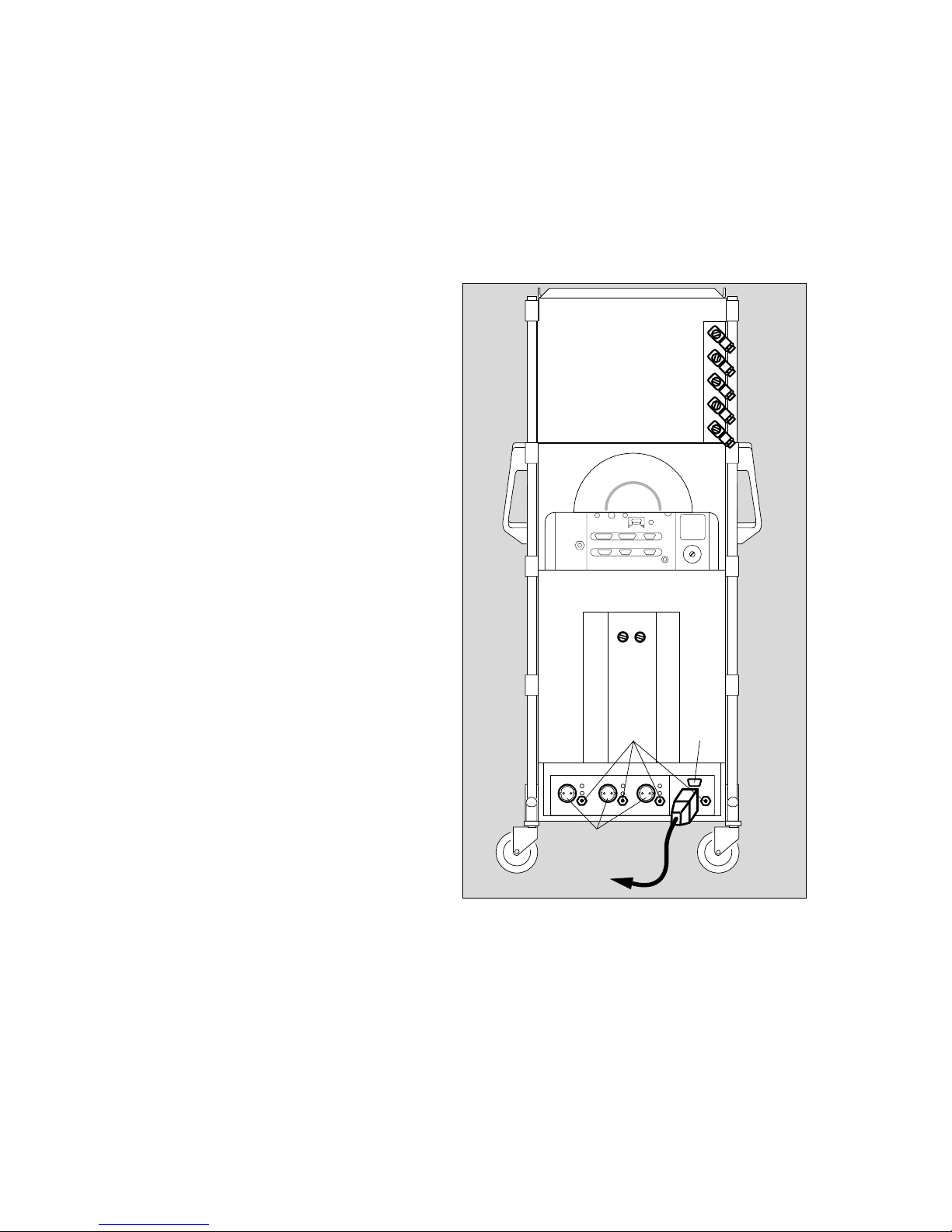
Connecting the equipment
The equipment must have been stripped down and tested
beforehand!
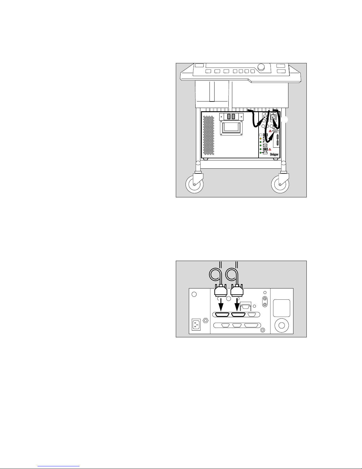
Electricity and gas supply
1 Plug the power cable into the mains socket.
2 Connect a ground lead for equipotential bonding to
one of the four pins on the rear of the workstation
when it is used for intracranial or intracardiac surgery.
The other end must be connected to the specified
point in the operating theatre.
3 Screw hoses for O2, AIR and N2O into the rear of the
equipment and plug connectors into the wall sockets.
● Check that the supply pressure is adequate on the
pressure gauges on the front (pointers must be in the
green area).
4 Holder for anaesthetic gas scavenging.
Auxiliary electrical equipment
5 Connect to the three auxiliary power sockets
(max. current per socket: 2 A). The auxiliary power
sockets are not controlled by the main switch.
If there is a power failure, the auxiliary power sockets
will be de-energised, because they are not powered
by the uninterruptible power supply (UPS).
Do not connect high-frequency surgery appliances to
the auxiliary power sockets.
Do not connect any other multiple sockets, e.g.
multiple socket adapters, to the auxiliary sockets.
The connection of equipment to the auxiliary sockets
causes an increase in leakage current.
The total leakage current in the power line must not
exceed 500 uA (EN 60601-1).
6 Sub-D socket for connecting the uninterruptible
power supply (UPS), see page 20.
On connection to the Sub-D socket, the UPS can be
switched off using the main switch.
The auxiliary power sockets and UPS are not
installed in the Cato ceiling version.
Preparing for use
Connecting the equipment
Electricity and gas supply
Auxiliary electrical equipment
18
1
2P
3
4
6
5
04237224
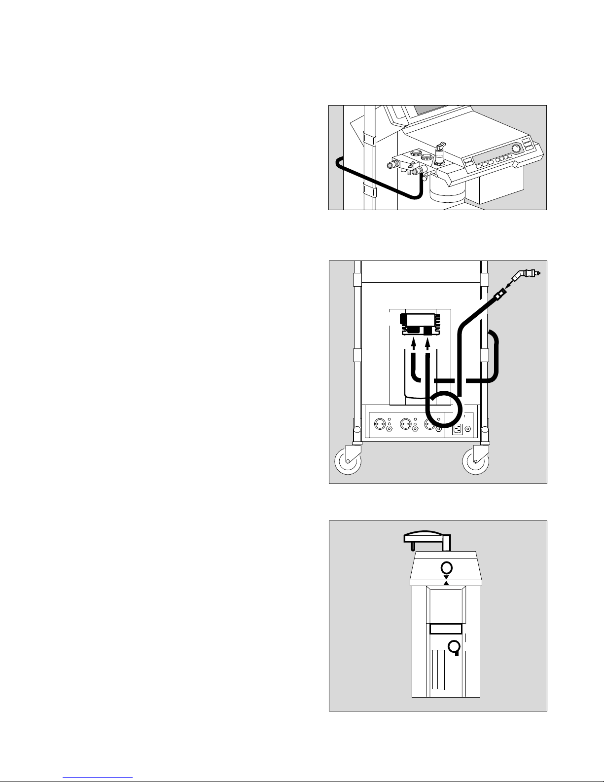
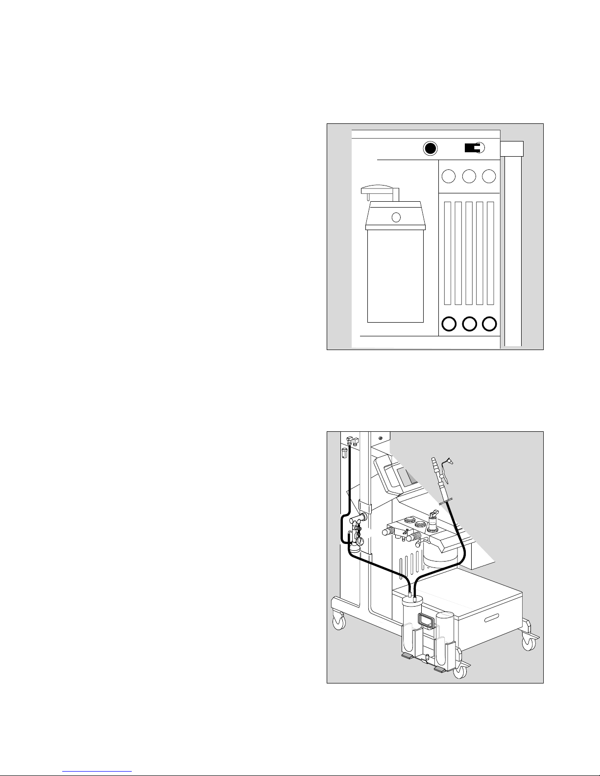
Anaesthetic gas scavenging system (AGS)
● Connect the transfer hose to the scavenging adapter
– first time only, it then remains in place.
1 Insert the scavenging adapter in the breathing system
from below until it engages.
2 Route the transfer hose round the equipment to the
rear.
3 Plug the transfer hose to the port on the collecting
system.
4 Connect the suction hose (sampling hose) to the port
on the collecting system.
5 Connect the anaesthetic scavenging connector to the
sampling hose.
6 Make sure that the second connector on the collecting
system is sealed with the screw plug.
● Follow the specific Instructions for Use of the
anaesthetic gas scavenging system.
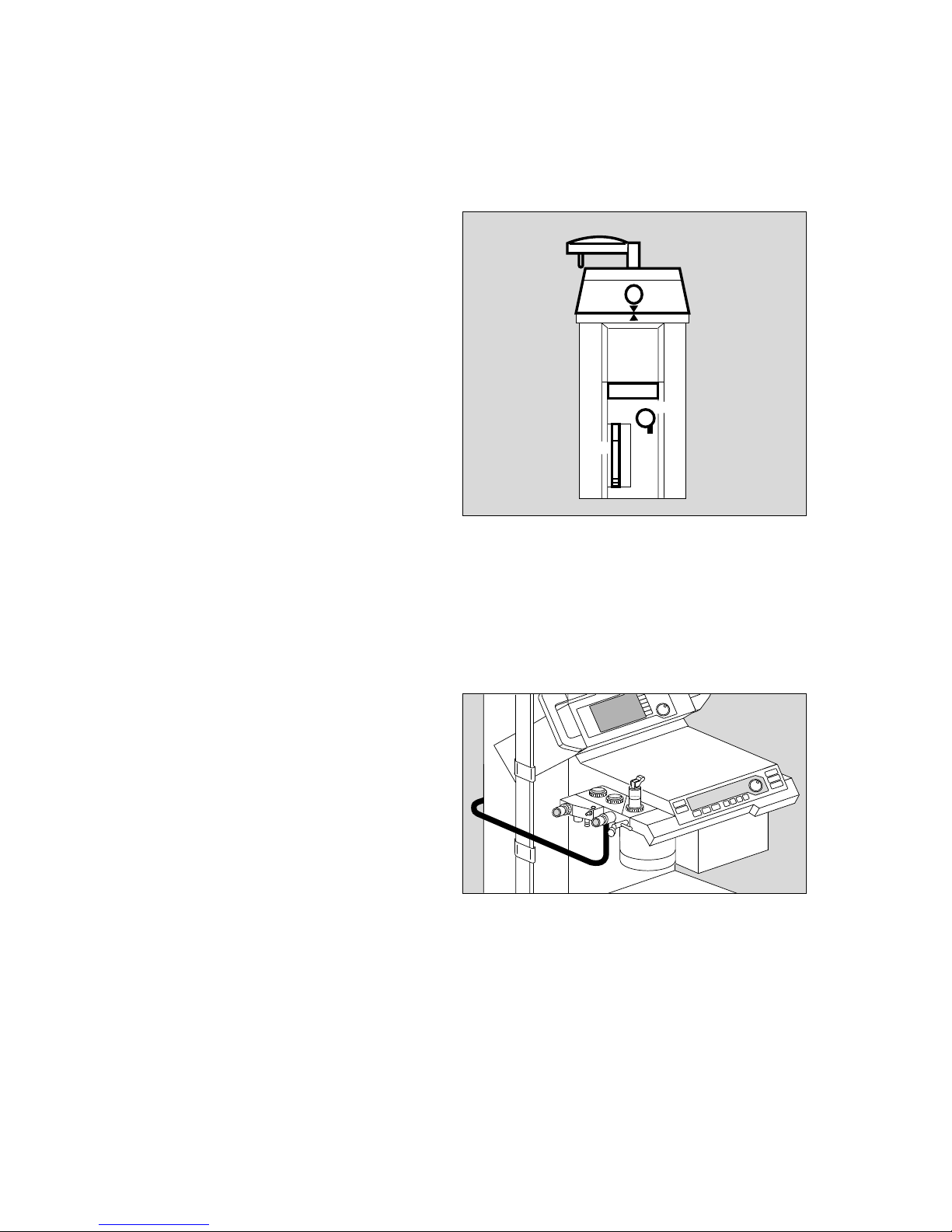
Anaesthetic agent vaporiser
The illustration shows a Vapor 2000
● If using the double connector for two Vapors, the
automatic Vapor identification system is disabled.
● Only use Vapors listed in the Order List.
● Follow the specific Instructions for Use of the Vapor.
● For each anaesthetic agent, only use the specified
Vapor.
7 Always insert the sealing plug and
8 secure with lever.
9 Engage control dial at »0« when no fresh gas is set.
10 Always secure the Vapor with the locking lever (turn
lever to the left as far as it will go).
19
Preparing for use
Connecting the equipment
Anaesthetic gas scavenging system (AGS)
Anaesthetic agent vaporiser
10
9
8
7
0
5
6
34
0292897000637224
G
A
S
1
2
02828970
Uninterruptible power supply
(optional, see separate Instructions for Use)
Make sure that the status line is connected, so that the
uninterruptible power supply (UPS) is controlled by Cato.
In the event of power failure, the machine is powered
by the battery of the UPS, but the auxiliary mains
socket on the back of the Cato will be de-energised.
However, auxiliary equipment powered by the refrigerator
connector on the side of the Cato will still be powered.
1 Plug the power plug of the Cato into the socket of the
UPS.
2 Plug the power plug of the UPS into the mains
socket.
The UPS can supply the Cato and connected auxiliaries
with electrical energy for about 45 minutes. It is automatically activated in the event of a power failure.
External equipment
See page 53 for the configuration of the interfaces.
Connection via the protocol interface
3 with data cable for printers with serial interface, e.g.
Desk-Jet (Hewlett-Packard)
or
e.g. the PM 8060 Vitara Patient Monitor with the
MEDIBUS protocol.
See page 53 for configuration.
Connection via the Dräger RS 232 C MEDIBUS
interface
e.g. to connect the PM 8060 Vitara Patient Monitor.
4 Connect with data cable.
● The equipment plugs must be secured with the
screws provided.
Preparing for use
Connecting the equipment
Uninterruptible power supply
External equipment
20
34
g
USV - Ein / On
manuell
S 3 S 4
S 5
S 6
I
0
F2 F2 F3 F4
1
2
0312897003228970

Checking readiness for operation
with checklist
It is assumed that the following conditions have
been met:
● The equipment and its accessory parts have been
cleaned and disinfected –
refer to page.......................................... 83 onwards
● The unit is fully equipped for the application in
question –
refer to page.......................................... 89 onwards
● The user has a good knowledge of the Instructions for
Use and has been trained to use the equipment.
● An emergency ventilation bag with appropriate mask is
available on the equipment.
● A checklist is affixed to the equipment.
The equipment must always be checked against the
checklist before it is used!
This check is mandatory as specified by EN 740!
Duration: approx. 5 minutes (depending on the scope
of calibration).
The equipment is subsequently in »standby« mode
when ready for use. Anaesthesia ventilation can
immediately be started at any time in this mode –
refer to page.......................................... 36 onwards
● Update the checklist by adding or deleting points
in accordance with the Instructions for Use, the
equipment type and configuration concerned and the
various supplementary units connected. It will then
contain all the requisite checks.
● Enter the model designation and serial number of the
equipment.
● Tick off ✔ the results of the checks in the ACTUAL
column.
● Remember to sign and date the checklist!
Test sequence
– Note any alterations and additions!
– Note the Instructions for Use of the individual units!
– If the checks do not proceed as planned, restore the
required status.
21
Preparing for use
Checking readiness for operation with checklist
Vapor
The illustration shows a Vapor 2000
1 The control dial is engaged at »0«.
2 Filling level OK – check filling level in viewglass.
– Last inspection less than six months ago.
Safety fill:
3 The sealing plug is inserted and secured with
the lever.
Plug adapter:
– The plug adapter lies horizontally and flush all round
on the sealing rings of the plug connection.
Interlock:
4 Plug-in system is locked – locking lever turned
clockwise until it engages.
Anaesthetic gas scavenging
– Is indicator in wall socket green? (Only when using
Dräger systems; note sounds of gas flow in other
cases.)
– Hose connector engaged below breathing system?
– The auxiliary air holes in the tube below the connector
must not be sealed, otherwise the breathing system
will be drained!
● Note the separate Instructions for Use for the
anaesthetic gas scavenging system.
22
Preparing for use
Checking readiness for operation with checklist
Vapor
Anaesthetic gas scavenging
0
1
4
2
3
D
G
A
S
0073722403428970
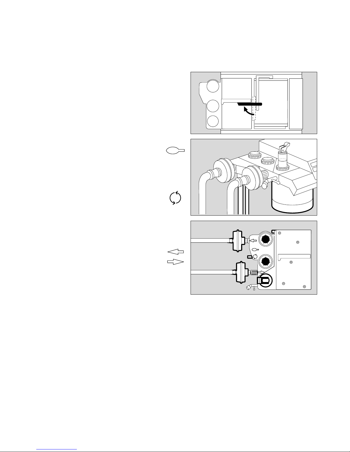
Breathing system
Lift off table top:
1 Lever set to the position shown in black.
The following are complete:
2 Hose with manual ventilation bag Symbol:
(Connected from below – not shown)
– Correct breathing hoses installed.
(Adult or infant hoses)
3 Pressure measuring hose with filter connected.
4 Measured gas return hose Symbol:
connected.
5 Fresh gas hose plugged in.
(Connected from below – not shown)
6 Valve discs inserted.
– Pressure limiting valve (APL) present.
– Inspiratory microbial filter. Symbol:
– Expiratory microbial filter. Symbol:
Soda lime
7 Lime has not noticeably changed colour (purple).
– Filling level adequate (up to the mark).
– Soda lime container is securely tightened – up to the
end stop (clockwise).
Emergency ventilation bag
(not shown)
– Bag is complete with mask and hung from the side
of the Cato.
– Bag functions correctly.
✔Check and tick off.
23
Preparing for use
Checking readiness for operation with checklist
Breathing system, Soda lime
Emergency ventilation bag
1
275
APL
3
4
6
035289700362897003728970
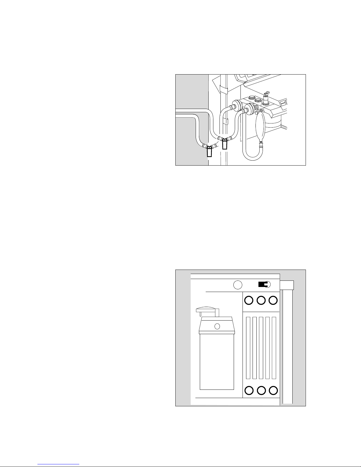
Water traps
1 Water traps are recommended in both the inspiratory
and the expiratory lines during prolonged anaesthesia,
low-flow anaesthesia and when using humidified
breathing gas.
– Water traps must be fitted at the lowest point in the
hose and hang downwards.
– Check regularly and drain if necessary.
Observe hygiene regulations –
risk of infection!
The hose system remains sealed. The container must
be replaced securely!
»Tips on reducing condensation« on page 136.
Reserve gas cylinders (optional)
● Open cylinder valves.
✔Check and tick off:
● Pressure indicator on O2 cylinder exceeds 50 bar? –
Pressure indicator on N2O cylinder exceeds 30 bar? –
Replace cylinders if not.
● Close cylinder valves!
Pipelinie gas supply
● Have connectors been pressed right into the wall
sockets for O2, AIR and N2O (not in holding
position!)?
✔Check and tick off:
2 Pointers of all three pressure indicators are in the
green range.
Gas delivery
3 Switch over to AIR.
4 Open O2 and AIR delivery valves until more than
9 L/min are indicated!
5 Open N2O delivery valve completely.
✔Check and tick off:
Does N2O measuring tube indicate 0?
3 Switch over to N2O.
✔Check and tick off:
Does N2O measuring tube indicate more than 9 L/min?
Does AIR measuring tube indicate 0?
24
Preparing for use
Checking readiness for operation with checklist
Water traps, Reserve gas cylinders
Pipelinie gas supply, Gas delivery
G
A
S
1
1
3
2
445
[
0382897000837224
Oxygen Ratio Control (ORC)
1 Slowly close O2 delivery valve –
– check:
the N2O flow decreases to less than 0.8 L/min
proportionally with the O2 flow for ORC low-flow,
the N2O flow decreases to »O« proportionally with
the O2 flow for S-ORC.
2 Switch over to »AIR«.
N2O flow decreases to »O«.
● Close N2O and AIR delivery valve.
O2 flush
3 Press button »O2+« –
– Is there a distinctly audible flow noise?
– Does the manual ventilation bag inflate?
✔Check and tick off!
Secretion aspirator (optional)
4 Open ejector valve –
5 Seal the aspiration holes on aspirator hose with your
finger (or fold over the hose).
Negative pressure indicated approx. – 0.8 bar?
✔Check and tick off!
● Close ejector valve.
Secretion aspirator may only be used in
»MAN/SPONT« mode or with disconnected
Y-piece.
25
Preparing for use
Checking readiness for operation with checklist
Oxygen Ratio Control (ORC)
O2 Flush, Secretion aspirator
D
G
A
S
5
4
2
1
3
[
0093722401037224
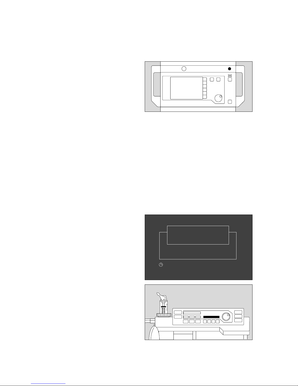
Power supply
● Equipotential bonding conductor connected?
● Mains plug connected?
1 Switch on equipment –
Press main switch to I.
Self-test
✔Check the signals and tick off the following on the
checklist:
● Lamp and alarm test, in succession:
Ventilator:
– Indication of the software version, all indicators light
up for approx. 2 seconds while a single tone sounds.
Monitor:
– The machine runs through the self-test:
All LEDs and display elements light up for
approx. 2 seconds. The LED in the Standby key E
continues to light up.
– Two alarm tones sound.
– The internal program memories are tested.
– The self-test is completed after approx. 1 minute.
The following display appears on the monitor:
»Self-test«
is displayed on the ventilator.
If the self-test reveals a fault of no relevance to the
safety of the equipment and not affecting any of the
measuring functions, the following message appears on
the monitor:
»Ready within limits«
together with a specific error message (refer to
pages 74 onwards). However, the equipment can be
operated nevertheless.
● Press the rotary control.
Call DrägerService.
26
Preparing for use
Checking readiness for operation with checklist
Power supply
Self-test
1
Technology for life
Cato
D
SW-Version 2.05
02-05-00
self-test
00137225 0113722404428970
If the self-test reveals a fault impairing the equipment's
safety, the following message appears on the monitor:
»Not ready«.
The machine cannot switch to Standby and cannot be
switched to measuring mode. DrägerService must be
called immediately.
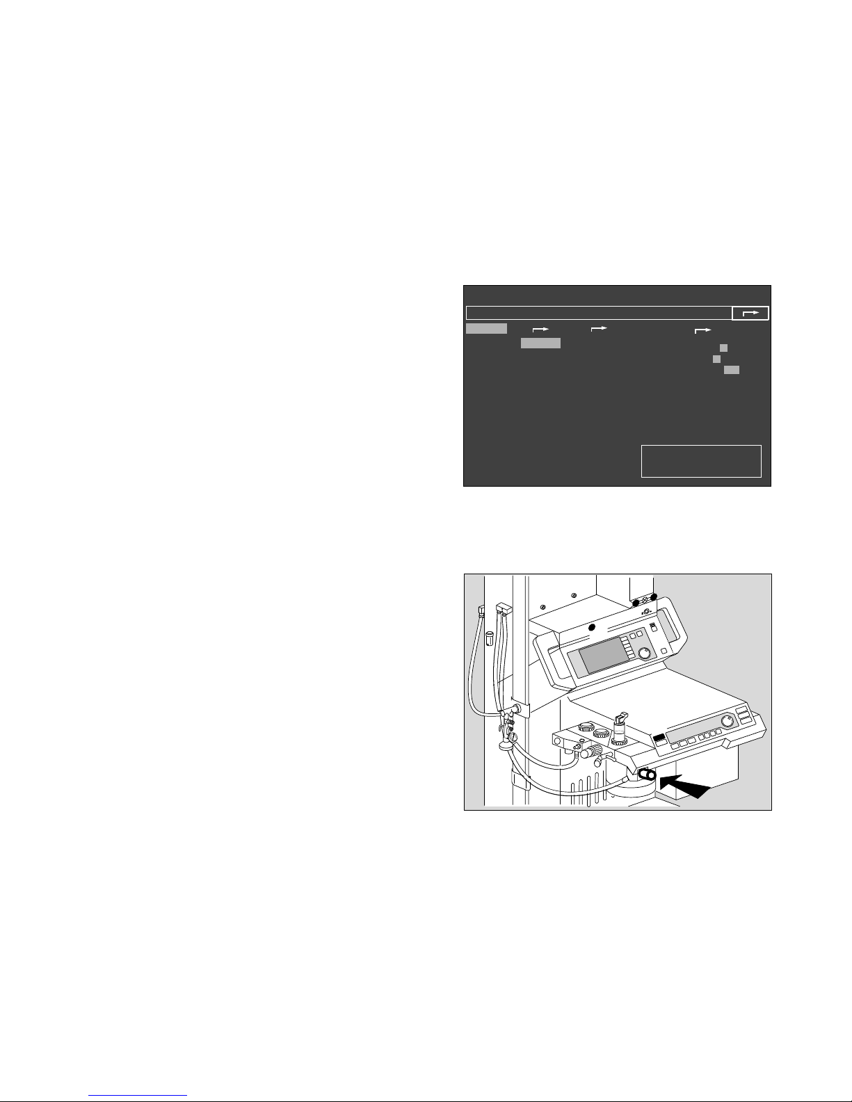
● The configuration menu is displayed after the self-test
(example):
Fresh gas - External outlet (optional)
Fresh gas outlet for connecting to semi-open systems.
1 Fit the hose of the semi-open system to the external
fresh gas outlet.
● Make sure the anaesthetic gas scavenging hose is
connected.
2 Set the desired O2 and N2O flow-rates on the
flowmeter block.
3 Press »MAN SPONT« on the ventilator.
4 The lamp in the »FRESH GAS OUTLET« key does not
light up.
● Check that pressure is building up in the circle system.
4 Switch on the fresh gas outlet –
Press »FRESH GAS OUTLET« key.
The lamp in the key lights up.
● Check that pressure builds up in the semi-open
system.
27
Preparing for use
Checking readiness for operation with checklist
Self-test
Fresh gas - External outlet
Standby / Configuration
✓
anaesth. gas
Halothane
Enflurane
Isoflurane
Sevoflurane
Desflurane
no
anaesth. gas
warning
default
✓
calibrating
O
2
-sensor
21 Vol.%
flow sensor
Ventilator
start up test
more
✓
Alarms inactive!
defaults
pulse to.
0 1 2 3 4 5 6 7 8 9
alarm tone 1 2 3 4 5 6 7 8 9
mode adult Neo.
parameters
record
interfaces
alarm limits
curves
basic configuration
D
P
M
8
050
0
I
G
A
S
1
3
4
2
0132897101237224

Selecting anaesthetic agent
The machine automatically identifies the newer Vapor
models with code for
halothane, enflurane and isoflurane,
sevoflurane and desflurane.
Sevoflurane and desflurane are only identified by
equipment built after July 1994 or which has been
upgraded.
Uncoded Vapors must be selected via the configuration
menu on the monitor.
The setting »no anaesth. gas« must be selected in
the configuration menu for ventilation without volatile
anaesthetic. This setting is activated automatically if a
Vapor is not connected.
The plug-in system of the new Vapor models features an
optical code allowing the machine to identify the Vapor:
– when the equipment is started up
– when the Vapor is changed during operation.
Incorrect anaesthetics are not detected!
However, the user can quite deliberately select a
different Vapor instead of that identified automatically.
The following advisory message is then displayed in
the alarm field on the monitor:
»AGT NOT SEL !«
If the Vapor has not been encoded:
The message
»Vapor not identified«
is displayed in the user advisory field of the configuration
menu in »standby« mode.
● Set the appropriate anaesthetic for the Vapor used.
If a Vapor has not been connected:
The message
»Vapor not present«
is displayed in the user advisory field of the configuration
menu in »standby« mode.
28
Preparing for use
Checking readiness for operation with checklist
Selecting anaesthetic agent
Automatic calibration of the O2/flow sensors
Sidestream calibration of the O2 measurement
(O2 sampling) and flow measurement are performed
automatically.
Automatic flow calibration is performed during the first
breaths after starting ventilation. There is therefore no
cause for panic if the measured values for the minute
ventilation still appear in grey (i.e. uncalibrated values,
see page 13) immediately after the self-test.
CO2 measurement must function correctly before
automatic flow calibration can be performed, otherwise
the flow sensor must be calibrated by hand.
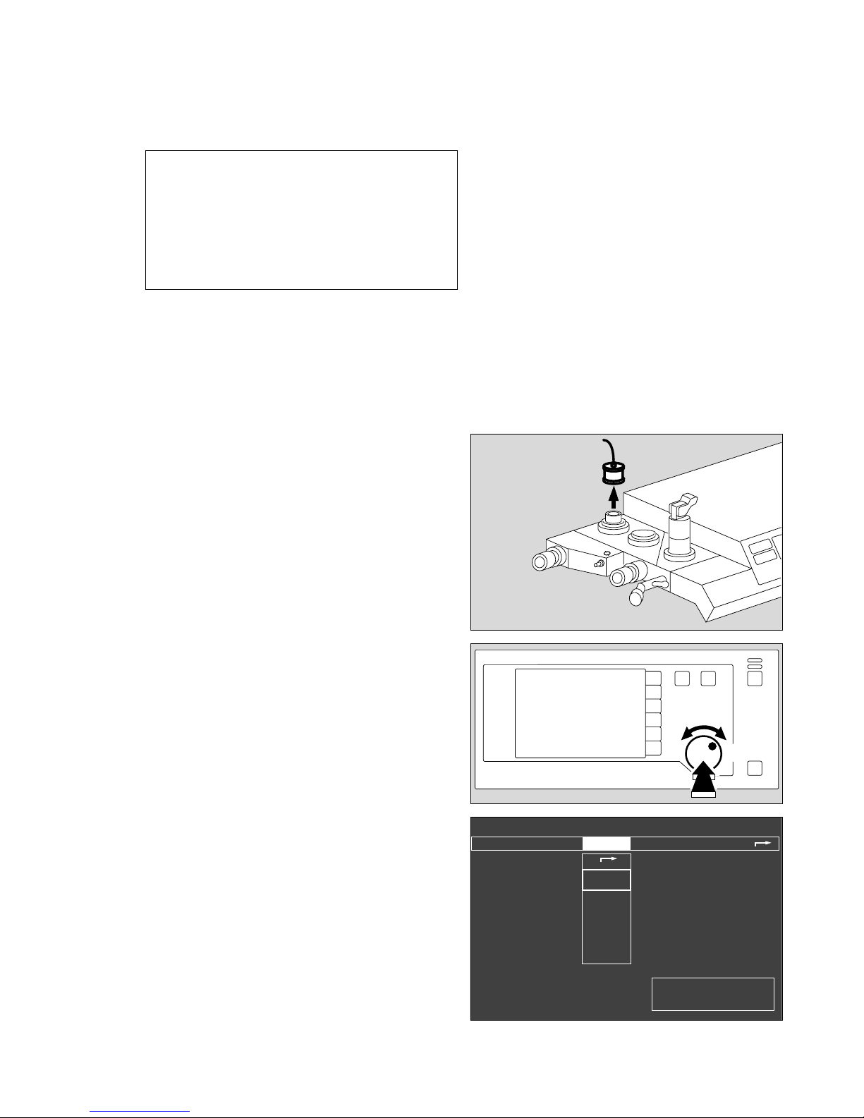
Manual calibration of the O2 sensor
The O2 sensor must be calibrated by hand if
O2 measurement has been set in the inspiratory line
(see “Parameters“ on page 53).
Calibrate O2 sensor with 21% O2 by volume = air
– The O2 sensor can be calibrated while flow calibration
is still in progress.
1 Remove the sensor from the inspiratory valve and
expose it to the ambient air – place it on the table and
wait at least two minutes.
2 Use the rotary control to select »calibrating« in the
»Standby/Configuration« menu and press to confirm.
● Move the cursor frame to
»O2 sensor
21Vol.%« by means of the rotary control.
● Press rotary control to confirm:
calibration starts.
1 Then plug O2 sensor onto the inspiratory valve again.
✔ Tick off in checklist.
29
Preparing for use
Checking readiness for operation with checklist
Automatic calibration of the O2/flow sensors
Manual calibration of the O2 sensor
The following symbols are used:
? = Enquires whether an action has been performed
or a setting made.
u
= Waiting period. The selected test step is being
performed by the machine.
✔ = The action has been completed successfully or
is not required.
Standby / Configuration
Alarms inactive!
calibrating
O
2
-sensor
21 Vol.%
flow sensor
Ventilatorstart up test
more
✓
Calibrate O
2
sensor after
replacing sensor and after 24 hrs.
Detach O
2
sensor and expose
for 2 min. to ambient air.
confirm !
✓
✓
2
G
A
S
1
01428971 0472897004828970
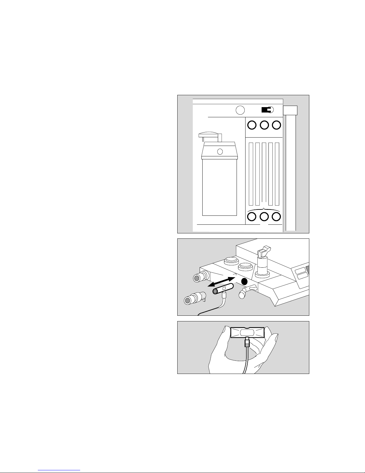
Manual calibration of the flow sensor
– The flow sensor can be calibrated by hand while O2
calibration is still in progress, either in the machine or
after being removed from the machine.
Without removal:
On the anaesthetic unit:
1 Set AIR/N2O selector to »AIR«.
2 Close the delivery valves for O2 and N2O, open the
delivery valve for air and thoroughly flush the
breathing system with air.
3 Close the delivery valve for air.
● Press the rotary control on the monitor to start
calibration.
The question mark (?) disappears and is replaced by
a timer icon ( u) on the screen.
A tick ( ✔ ) appears on the screen when calibration
has been completed correctly.
✔Tick off in checklist.
The cursor frame has automatically jumped to
»Ventilator start-up test«.
With removal:
4 Remove flow sensor:
– Unscrew expiration nozzle
– Remove flow sensor
– Briefly swing it to flush with ambient air
– Hold it horizontally with the cable connection pointing
downwards (calibration in installation position
improves the measuring accuracy)
– Seal off one or both sides as shown on the right,
preferably with your thumb or palm.
● Press the rotary control on the monitor to start
calibration; continue as above.
4 Replace flow sensor!
30
Preparing for use
Checking readiness for operation with checklist
Manual calibration of the flow sensor
4
2
1
3
2
013372240512897005228970
 Loading...