

Page 1
DR
SAFETY & OPERATING INSTRUCTIONS
®
REDI-PLOW™ PLUS
DR Power Equipment
Serial No.
Order No.
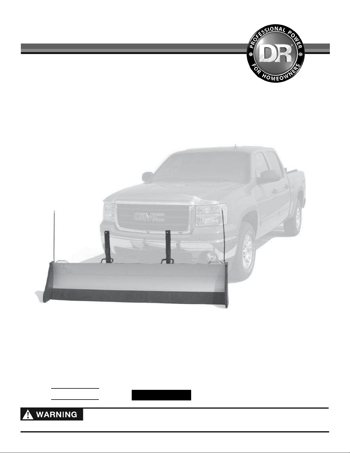
Read and understand this manual and all instructions before operating the DR® REDI-PLOW™ PLUS.
Original Language
Toll-free phone: 1-800-DR-OWNER (376-9637)
Fax: 1-802-877-1213
Website: www.DRpower.com
Page 2

Table of Contents
y
Chapter 1: General Safety Rules ............................................................................................................................................................ 4
Chapter 2: Setting Up The DR® REDI-PLOW™ PLUS.......................................................................................................................... 6
Chapter 3: Operating The DR® REDI-PLOW™ PLUS .......................................................................................................................... 12
Chapter 4: Parts Lists and Schematic Diagrams .................................................................................................................................. 14
Conventions used in this manual
This indicates a hazardous situation, which, if not avoided, could result in death or serious injury.
This indicates a hazardous situation, which, if not avoided, could result in minor or moderate injury.
This information is important in the proper use of your machine. Failure to follow this instruction could result in damage
to
our machine or property.
Serial Number and Order Number
A Serial Number is used to identify your machine and is located on the Serial Number Label on your machine. An Order Number
is used to check and maintain your order history and is located on your packing slip. For your convenience and ready reference,
enter the Serial Number and Order Number in the space provided on the front cover of this manual.
Additional Information and Potential Changes
DR Power Equipment reserves the right to discontinue, change, and improve its products at any time without notice or obligation
to the purchaser. The descriptions and specifications contained in this manual were in effect at printing. Equipment described
within this manual may be optional. Some illustrations may not be applicable to your machine.
2 DR
®
REDI-PLOW™ PLUS
Page 3

CONTACT US AT www.DRpower.com 3
Page 4
Chapter 1: General Safety Rules
Read this safety & operating Instructions manual before you use the REDI-PLOW. Become familiar with the operation and
service recommendations to ensure the best performance from your machine. If you have any questions or need assistance,
please contact us at www.DRpower.com or call toll-free 1-800-DR-OWNER (376-9637) and one of our Technical Support
Representatives will be happy to help you.
Labels
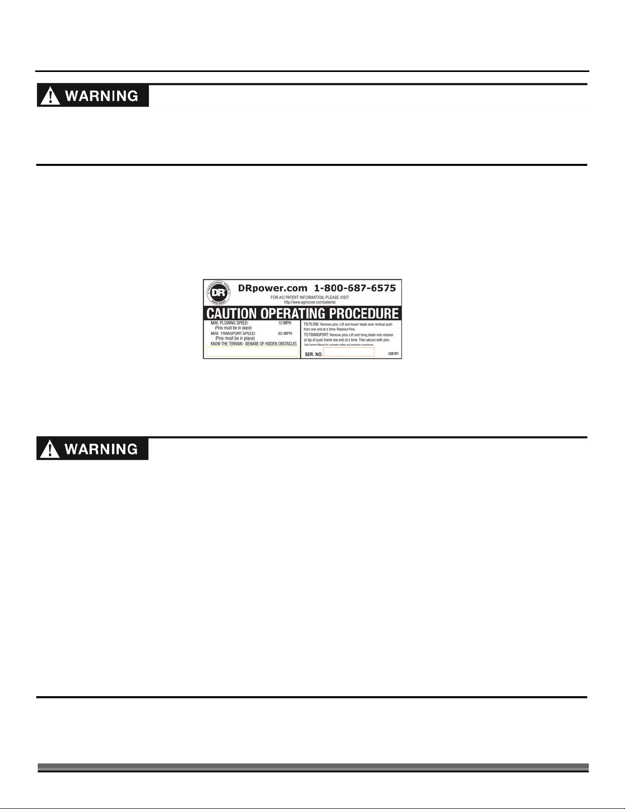
Your REDI-PLOW carries prominent labels as reminders for its proper and safe use. Shown below are copies of the Safety and
Information labels that appear on the equipment. Take a moment to study them and make a note of their location on your REDIPLOW as you set up and before you operate the unit. Replace damaged or missing safety and information labels immediately.
#33619
Operating the Plow Safely
The vehicle the plow is attached to is a heavy, high-powered machine. You must operate the vehicle safely. Unsafe operation can
create a number of hazards for you, as well as anyone else in the nearby area. Always take the following precautions when using
this vehicle and Plow:
Keep in mind that the operator or user is responsible for accidents or hazards occurring to other people, their property, and
themselves.
Keep bystanders at least 50 feet away from your work area at all times. Stop and shut off the vehicle engine when another
person or pet approaches.
Remember – always exercise safety, courtesy, and common sense.
Avoid overloading your equipment - push only enough snow with each pass to get the job done.
When transporting blade, secure it to hanger brackets with pins or locks.
Do not exceed 65 MPH when transporting plow.
Do not exceed 10 MPH when plowing.
Never pile snow on someone else’s property, on street or sidewalks, by fire hydrants, mailboxes, water drains or electrical
boxes.
Check with local regulations before pushing snow across roads-it may be illegal.
Do not pile snow near handicapped or parking areas.
Plow snow during low-traffic hours - be cautious of pedestrians and vehicles.
Never pile snow where it obstructs visibility of traffic.
4 DR
®
REDI-PLOW™ PLUS
Page 5

Operating the Plow Safely (continued)
Use lowest transmission gear, on 4WD select low range if equipped.
On manual transmission avoid riding the clutch.
Be aware of engine temperature - avoid overheating.
When backing up don’t rely on rear view mirrors-turn around and look where you are going.
Never plow with your head out of the window-an unexpected sudden stop could result in personal injury.
Always wear your seat belt-even when plowing snow.
Follow vehicle manufacturers specifications for snowplowing.
Never operate the machine when under the influence of alcohol, drugs, or medication.
Keep all nuts and bolts tight and keep the equipment in good operating condition.
When pushing snow onto a pile, always do so with blade in the straightforward position. Piling snow with blade angled may
cause damage to plow or vehicle components.
Use caution when plowing next to a building wall. Make first pass about 3 feet away, make second pass about 2 feet away and
third pass about 1 foot away.
Safety for Children and Pets
Tragic accidents can occur if the operator is not alert to the presence of children and pets. Children are often attracted to the
machine and the plowing activity. Never assume that children will remain where you last saw them. Always follow these
precautions:
Keep children and pets out of the working area and under the watchful care of a responsible adult.
Be alert and turn the vehicle off if children or pets enter the work area.
Never allow children to operate the REDI-PLOW.
Use extra care when approaching blind corners, shrubs, trees, or other objects that may obscure your vision.
A Note to All Users
No list of warnings and cautions can be all-inclusive. If situations occur that are not covered by this manual, the operator must
apply common sense and operate this REDI-PLOW in a safe manner. Contact us at www.DRpower.com or call 1-800-DR-OWNER
(376-9637) for assistance.
CONTACT US AT www.DRpower.com 5
Page 6

Chapter 2: Setting Up The DR
®
REDI-PLOW™ PLUS
Assembly
Tools and Supplies needed:
Ft. lb. Torque Wrench
Impact or Ratchet with 9/16” and 3/4” Socket
Drill with 3/16” and 5/16” Drill Bit
#3 Phillips Driver Bit
Box Wrench 3/4”
Open Wrench 5/16”
Allen Wrench 3/16”
2 Short Pcs. of 2 X 4 Blocking
Bubble Level
Protective Eyewear
Note: Prior to plow assembly, park vehicle on level grade and install plow mount
receiver (shipped separately). Clearance under receiver should measure
between 8 to 16 inches above grade (Figure 1). Interceptor can be installed
with leg turned up or down as needed for proper push frame clearance
(Shown turned up in illustrations).
1. Insert interceptor into receiver – leg up. Secure with pins (interceptor has
choice of holes to allow for clearance when aligning blade). Hold push frame
against interceptor. Select 4 bolt hole pattern that positions push frame 8"
to 10" above grade. If lowest bolt pattern is too high, remove interceptor
and turn leg down. Bolt push frame (4 bolts 1/2" x 4" w/flat washers and
lock nuts) to proper hole height on interceptor – leave bolts snug tight for
now.
Receiver Clearance
8" - 16"
Figure 1
Interceptor
Push Frame
4 Bolts 1/2" x 4",
8 Flat Washers,
4 Lock Nuts
Push Frame
Clearance 8" - 10"
2. Push set collar tight against receiver – hold and tighten set screw with 3/16"
Allen wrench (Figure 2).
3. With bolts snug tight, level push frame horizontally (Figure 3).
4. Check push frame for vertical plumb (Figure 4). If plumb, tighten 4 bolts
now and go to step 5. If not plumb, refer to the following shim procedure.
Bubble
Plumb
Figure 2
Figure 3
8" - 10"
Bubble Level
8" - 10"
Figure 4
6 DR
®
REDI-PLOW™ PLUS
Page 7

Figure 5
A
A
A
A
d
J
Shim Here
5. If the push frame leans towards front of vehicle. Shim at top pair of bolts
(Figure 5). If the push frame leans away from front of vehicle. Shim at
bottom pair of bolts (Figure 6).
WHEN SHIMMING IS COMPLETE – TIGHTEN ALL BOLTS.
6. Refer to exploded view components for plow blade parts before performing
next step (Figure 7).
Note: Rubber Blade should be room temperature before assembly.
7. Apply soapy water solution to channel areas of the Rubber Blade and bottom
section of Aluminum Blade where they will mate together (Figure 8).
8. Slide end of rubber edge with matching channel in bottom half of aluminum
blade and center on bottom half.
9. Turn bottom half of blade over and set it on wood blocks, one at each end as
shown (Figure 9). Take top half and connect tongue and groove joint with
bottom half. Slide top half until centered with bottom half of blade.
Figure 6
End Plate
Bottom
Section of
luminum
Blade
Figure 7
Shim Here
Blade Marker
Rubber Blade
Slide Hinge
Box End
Top
Section of
luminum
Blade
Rubber
Blade
Figure 8
Tongue an
Groove
oint
Figure 9
Bottom Section of
luminum Blade
pply Soapy
Water Solution
Use 2x4 to prop
bottom of Blade
up at both ends
CONTACT US AT www.DRpower.com 7
Page 8

10. Place each side hinge on blade and align edge of hinge with factory mark on
A
A
A
A
blade (Figure 10).
11. When both hinges are properly aligned – they should measure 22 1/2" apart
(Figure 11).
12. At end of blade, insert two square nuts in each channel – flat side facing out.
Slide nuts over to hinge and align them with holes at top and bottom (Figure
12).
13. Turn 3/8" x 3/4" hex bolts with flat washer into nuts on top section of blade
and leave loose (Figure 13). Turn 3/8" x 3/4" hex bolts into nuts on bottom
section of blade and leave loose.
14. Make sure slide hinge is lined up with mark (Figure 10). Using 9/16"
wrench, tighten hex bolts in top section first (Figure 14). Then tighten hex
bolts on bottom section.
15. Using 5/16" bit, drill a hole through blade in each factory punched hole on
slide hinge (Figure 15). Turn a (short) 3/8" self threading bolt into each
drilled out hole and tighten. Repeat steps to attach opposite slide hinge.
lign this edge of each Slide
Hinge with Factory mark
Slide Hinge
Factory Marks
on Blade
22-1/2" apart
Figure 10
22-1/2"
Tighten these
bolts second
Figure 14
Drill 5/16" Hole
in Blade
Figure 15
Tighten these
bolts first
Factory
Hole in
Slide
Hinge
Figure 11
lign Square Nut here at bottom
lign edge
with Factory
Mark
lign Square
Nut here at top
Figure 12
Bottom
Hex Head
Bolt
w/Flat
Washer
Top Hex Head Bolt w/Flat
Washer (loose for now)
Figure 13
8 DR
®
REDI-PLOW™ PLUS
Page 9

Drill 5/16" Hole at
#
Factory Mark (1 at
each end)
Figure 16
16. At tongue and groove joint, drill a 5/16" pilot hole at factory mark in v-
groove at each end of blade (Figure 16).
17. Using a 9/16" wrench, turn a (short) 3/8" self threading bolt into 5/16" pilot
hole and tighten (Figure 17). Repeat at other end.
18. Using torque wrench, tighten all (6) bolts on each slide hinge to 31 ft/lbs.
(Figure 18).
19. At bottom of blade, check to make sure rubber edge is centered, then drill a
3/16" pilot hole at factory mark in v-groove (4 locations) – drill only through
first layer of aluminum and into rubber (Figure 19). Repeat this drilling
procedure for three remaining marks.
20. Using Phillips #3 bit, run a self drilling screw into each of the four pilot holes
(Figure 20). This prevents rubber from movement.
21. Hang blade on push frame in the transport position and insert key hole pins
(Figure 21).
22. Attach tether cord to pins by feeding end of cord through hole in pin and
tying a square knot (Figure 22).
3 Philips
Self Drilling
Screw
3/8" Self
Threading Bolt
Figure 17
*Torque Bolts to 31 ft/lb.
Figure 18
3/16" Drill Bit
Factory
Mark
(4X)
Figure 20
Keyhole Pin
Slide Hinge
Figure 21
Tether
Cord
Square
Figure 19
Figure 22
CONTACT US AT www.DRpower.com 9
Knot
Page 10

23. Insert two square nuts into top channel (Figure 23). Turn a hex head jam
r
J
f
nut onto the stud of blade marker and align marker with hole on lift handle
and bolt marker and handle to blade using square nut in channel.
24. Turn 3/8" x 3/4" bolt into other hole on handle and thread to nut in channel
(Figure 24). Position the handle flush with blade edge. Then tighten both
bolts on lift handle. Repeat at other end.
25. Attach rubber end and metal cap plate to end of blade with four long self
threading bolts (Figure 25).
26. Tighten all bolts until rubber begins to compress to blade. Insert a 5th bolt
to tighten bottom of rubber to bottom of end plate. Use flat washer and lock
nut (Figure 26).
27. Tighten all bolts equally. Repeat box end assembly at opposite end (Figure
27).
Blade
Marke
Hex Head
am Nut
2 Square Nuts
in Channel
lat side up
Figure 23
Bolt
Figure 26
Lock Nut
Flat
Washer
Figure 24
Four Long Self
Threading Bolts
Metal End Cap
Rubber Box End
Figure 27
10 DR
®
REDI-PLOW™ PLUS
Figure 25
Page 11

CONTACT US AT www.DRpower.com 11
Page 12

Chapter 3: Operating The DR® REDI-PLOW™ PLUS
Basic Snowplowing Practices and Tips
The REDI-PLOW is designed to make moving snow convenient and easy. By following these simple practices, snow removal can
be safe and enjoyable.
If blade is kept in warm storage, set blade outside and allow to cool-this prevents snow from freezing to blade when plowing.
Setting the blade straight forward is the most efficient way to move snow.
Always keep current with fresh snowfall, it’s easier to plow fresh snow. Wet snow can compact and freeze which requires
chipping to break it loose before attempting to move it.
From the start of the season, push the snow far enough out to allow for future snowfalls.
Avoid overloading your equipment-push only enough snow with each pass to get the job done.
When pushing snow onto a pile, always do so with blade in the straight forward position. Piling snow with blade angled may
cause damage to plow or vehicle components.
When pushing new snow to stack up against hardened piles, start a new pile first and then push it up on to hard pile.
Use caution when plowing next to a building wall. Make first pass about 3 feet away, make second pass about 2 feet away and
third pass about 1 foot away.
When transporting blade, secure it to hanger brackets with pins or locks.
On 4WD select low range, if equipped.
Always know the terrain before plowing.
Operating instructions
The design of your plow is for pushing snow. Do not use it for any other purpose as it could cause damage to the plow or
machine.
Before performing any adjustments to the plow or any other procedure or inspection, stop the vehicles engine, set the parking
brake and remove the key.
Read and understand all safety warnings listed in Chapter 2 “General Safety
Keyhole Pins Secure Blade
During Transporting
Figure 28
Keyhole Pins Reinstalled To
Secure Blade During Plowing
Rules” before using your REDI-PLOW.
Note: If blade is kept in warm storage, set blade outside and allow to cool - this
prevents snow from freezing to blade when plowing.
LOWERING THE BLADE FOR PUSHING SNOW:
1. Step behind the Plow and remove the keyhole pin (Figure 28).
2. Lift one side of the blade out of retainer until the slide hinge fits over the
push bar, then lower blade to ground.
3. Re-insert keyhole pin (Figure 29). Repeat same procedure for other side of
blade.
TO PUSH SNOW:
Follow vehicle manufacturers’ specifications for snowplowing.
Note: Do not exceed 10 MPH when plowing.
Figure 29
12 DR
®
REDI-PLOW™ PLUS
Use lowest transmission gear, on 4WD select low range if equipped.
Page 13

4. To start a pass, Drive forward slowly allowing for tire traction and for the
A
A
A
blade to accumulate snow.
5. As you come to the end of the pass, reduce speed and start applying brakes
as needed.
6. Back up to disengage the blade and continue backing up until you are
realigned for next push.
7. Repeat this procedure until job is finished. Deep and/or compacted snow
may require several passes.
The blade can be angled by removing swivel pin, turning blade to desired angle
position and reinserting pin (Figure 30).
Angled Interceptor Note: There are two holes in the interceptor shaft. When
inserting angle interceptor into front mount receiver,
select the hole which allows blade to swing as far as
possible without contacting vehicle.
TO STORE BLADE FOR TRANSPORTING:
Reverse procedure from “Lowering the Blade for Pushing Snow” and re-insert
keyhole pins (Figure 28).
Do not exceed 65 MPH when transporting plow.
Note: When transporting blade, secure it to hanger brackets with pins or locks.
Swivel Pin
ngle
Interceptor
Push Frame
Straight Position
ngled to Right
ngled to Left
Figure 30
CONTACT US AT www.DRpower.com 13
Page 14

Chapter 4: Parts Lists and Schematic Diagrams
Parts List – DR® REDI-PLOW™ PLUS
Note: Part numbers listed are available through DR Power Equipment.
Ref# Part# Description
1 33601 Aluminum Blade, Top, 82"
2 33602 Aluminum Blade, Bottom, 82"
3 33603 Rubber Cutting Edge, 82"
4 33604 Rubber Box End
5 33605 Metal End Cap
6 33606 Slide Hinge
7 33607 Bolt, Self Threading, 3/8" x 1" ZP
8 33608 Bolt, Hex Head, 3/8" x 3/4" ZP
9 33609 Washer, Flat, 3/8" ZP
10 33610 Push Frame w/Hardware Kit
33611 Hardware Kit, Push Frame
11 33612 Keyhole Pin
12 33613 Lift Handle
13 33614 Bolt, Self Threading, 3/8" x 2- 1/2" ZP
14 33615 Bolt, Hex, 1/2" x 4" GR 8 ZP
Ref# Part# Description
15 33616 Nut, Lock, 1/2'' ZP
16 33617 Washer, Flat, 1/2" ZP
17 33618 Nut, Square, 3/8'' ZP
18 33619 Label, Operation & S/N, RDP Plus
19 33620 Leveling Shim
20 33621 Hitch Pin
21 33622 Hair Pin
22 33623 Blade Marker Kit, Top Mount
23 33624 Angle Interceptor Kit
24 33625 Swivel Pin
25 33626 Set Collar
26 33627 Bolt, 3/8" x 1- 3/4" GR 5 ZP
27 33628 Nut, Nylon Lock, 3/8'' ZP
28 33629 Screw, Self Drilling, #14 x 1" ZP
- 34007 Label, RDP Plus Logo
14 DR
®
REDI-PLOW™ PLUS
Page 15

DR
®
REDI-PLOW™ PLUS
2-Year Limited Warranty
Terms and Conditions
The DR
to ordinary and normal consumer use; ninety (90) days for any other use.
For the purposes of all the above warranties, “ordinary and normal consumer use” refers to non-commercial
residential use and does not include misuse, accidents, or damage due to inadequate maintenance.
DR
this type is used. DR
duration to a period of two (2) years in consumer use, ninety (90) days for any other use.
The 2-Year Limited Warranty on the DR
The 2-Year Limited Warranty is applicable only to the original owner.
The warranty holder is responsible for the performance of the required maintenance as defined by the manufacturer's
owner's manuals. This warranty does not cover attachments and accessories to the machine.
REDI-PLOW™ PLUS is warranted for two (2) years against defects in materials or workmanship when put
Power Equipment certifies that the DR
Power Equipment however, limits the implied warranties of merchantability and fitness in
REDI-PLOW™ PLUS is fit for ordinary purposes for which a product of
REDI-PLOW™ PLUS starts on the date the machine ships from our factory.
During the warranty period, the warranty holder is responsible for the machine transportation charges, if required.
During the warranty period, warranty parts will ship by standard method at no charge to the warranty holder.
Expedited shipping of warranty parts is the responsibility of the warranty holder.
SOME STATES DO NOT ALLOW LIMITATIONS ON THE LENGTH OF IMPLIED WARRANTIES, SO THE ABOVE
LIMITATIONS MAY NOT APPLY TO YOU.
DR
Power Equipment shall not be liable under any circumstances for any incidental or consequential damages or
expenses of any kind, including, but not limited to, cost of equipment rentals, loss of profit, or cost of hiring services
to perform tasks normally performed by the DR
SOME STATES DO NOT ALLOW THE EXCLUSION OR LIMITATION OF INCIDENTAL OR CONSEQUENTIAL
DAMAGES, SO THE ABOVE LIMITATIONS MAY NOT APPLY TO YOU.
THIS WARRANTY GIVES YOU SPECIFIC LEGAL RIGHTS, AND YOU HAVE OTHER RIGHTS, WHICH VARY FROM
STATE TO STATE.
REDI-PLOW™ PLUS.
15 DR
®
REDI-PLOW™ PLUS
Page 16

Daily Checklist for the DR® REDI-PLOW™ PLUS
To help maintain your REDI-PLOW for optimum performance, we recommend you follow this checklist each time you use your machine.
Before performing any adjustments to the plow or any other procedure or inspection, stop the vehicles engine, set the parking
brake and remove the key.
[ ] RUBBER BLADE: Check the Blade for wear or damage.
[ ] GENERAL CONDITION: Check the general condition of the machine, e.g.; nuts, bolts, welds etc.
End of Season and Storage
Before performing any adjustments to the plow or any other procedure or inspection, stop the vehicle’s engine, set the parking
brake and remove the key.
For maximum blade life, periodically retighten bolts and protect blade from sun by storing it inside or covered.
75 MEIGS ROAD, P.O. BOX 25, VERGENNES, VERMONT 05491
©2013 Country Home Products, Inc. All rights reserved PN 80771_ 090113 / CHP 336491
 Loading...