

Page 1
®
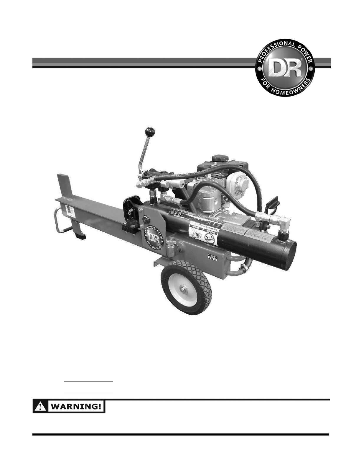
8-TON DR
WOOD SPLITTER
SAFETY & OPERATING INSTRUCTIONS
DR Power Equipment
Serial No.
Order No.
READ AND UNDERSTAND THIS MANUAL AND ALL INSTRUCTIONS BEFORE OPERATING THIS 8-TON
DR WOOD SPLITTER.
Toll-free phone: 1-800-DR-OWNER (376-9637)
Fax: 1-802-877-1213
Website: www.DRpower.com
Page 2

Table of Contents
Chapter 1: General Safety Rules..........................................................................................................4
Chapter 2: Setting Up Your 8-Ton DR Wood Splitter .........................................................................9
Chapter 3: Operating Your Wood Splitter.........................................................................................18
Chapter 4: Inspection And Maintenance .......................................................................................... 22
Chapter 5: Troubleshooting...............................................................................................................27
Chapter 6: Class II Receiver Mount Accessory .................................................................................29
Chapter 7: Parts Lists, Schematic Diagrams And Warranty............................................................. 32
Conventions used in this manual
THIS INDICATES A HAZARDOUS SITUATION, WHICH, IF NOT FOLLOWED, WILL RESULT IN DEATH
OR SERIOUS INJURY.
THIS INDICATES A HAZARDOUS SITUATION, WHICH, IF NOT AVOIDED, COULD RESULT IN DEATH
OR SERIOUS INJURY.
THIS INDICATES A HAZARDOUS SITUATION, WHICH, IF NOT AVOIDED, COULD RESULT IN MINOR
OR MODERATE INJURY.
THIS INFORMATION IS IMPORTANT IN THE PROPER USE OF YOUR MACHINE. FAILURE TO FOLLOW
THIS INSTRUCTION COULD RESULT IN DAMAGE TO YOUR MACHINE OR PROPERTY.
2 8-TON DR
®
WOOD SPLITTER
Page 3

Serial Number and Order Number
A Serial Number is used to identify your machine and is located on the Serial Number Label on your
machine. An Order Number is used to check and maintain your order history and is located on the
upper left portion of your packing slip. For your convenience and ready reference, enter the Serial
Number and Order Number in the space provided on the front cover of this manual.
Additional Information and Potential Changes
DR Power Equipment reserves the right to discontinue, change, and improve its products at any time
without notice or obligation to the purchaser. The descriptions and specifications contained in this
manual were in effect at printing. Equipment described within this manual may be optional. Some
illustrations may not be applicable to your machine.
Specifications
MECHANICAL SPECIFICATIONS
Slide Rail...................................................................... 4" x 4", reinforced, heavy duty, steel tube
Wedge.......................................................................... high-carbon steel, 3/4" thick
Force/Tonnage............................................................ 8 ton
Cylinder Stroke ............................................................ 18"
Log Opening ............................................................... 18" maximum
Operating Weight........................................................ 138 LBS
Engine.......................................................................... 475 Power Built series Briggs & Stratton; 4.75 ft. lbs.
torque (148cc)
HYDRAULIC SPECIFICATIONS
Cylinder Size................................................................ 3" x 18", trunnion mount cylinder, 1.25" rod
Hydraulic System Capacity
(including cylinder, tank, and hoses)......................... 154 oz. (4.5 liters)
Safety Release Control Valve ...................................... Detent, auto return
Gear Pump .................................................................. single-stage, 2.7 GPM
Hydraulic Fluid
Above 30° F ................................................................. Use AW-32, 10W tractor hydraulic oil (non foaming)
or ATF Dextron III
Below 30° F.................................................................. Use only ATF Dextron III
SHIPPING SPECIFICATIONS
Shipping Weight.......................................................... 148 LBS
Contact us at www.DRpower.com 3
Page 4
Chapter 1: General Safety Rules
READ THIS SAFETY AND OPERATING MANUAL BEFORE YOU USE THE 8-TON DR WOOD SPLITTER.
BECOME FAMILIAR WITH THE SERVICE RECOMMENDATIONS TO ENSURE THE BEST
PERFORMANCE FROM YOUR SPLITTER.
DO NOT ATTEMPT TO ASSEMBLE, OPERATE, OR MAINTAIN OUR PRODUCT WITHOUT FULLY
UNDERSTANDING ALL OUR INSTRUCTIONS AND SAFETY PRECAUTIONS. DO NOT OPERATE THE
WOOD SPLITTER UNLESS YOU READ AND UNDERSTAND THE INSTRUCTIONS AND WARNINGS IN
THIS MANUAL. IF YOU ARE EVER UNSURE ABOUT AN ACTION YOU ARE ABOUT TO TAKE, DON’T
DO IT. CONTACT US AT WWW.DRPOWER.COM OR CALL DR POWER EQUIPMENTS’ TOLL-FREE
SUPPORT AT 1-800-DR-OWNER (376-9637) FOR HELP OR INFORMATION.
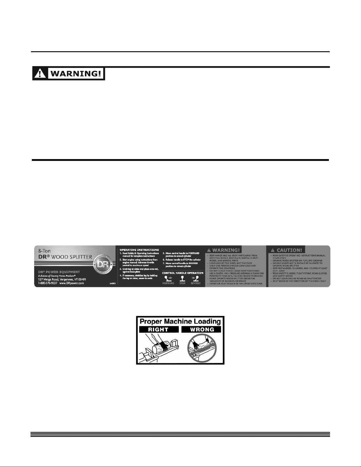
Labels
Your 8-TON DR WOOD SPLITTER carries prominent labels as reminders for its proper and safe use.
Shown below are copies of all the safety and operation labels that appear on the equipment. Take a
moment to study them and make a note of their location on your 8-TON DR WOOD SPLITTER as you
assemble and before you operate the unit. Replace damaged or missing safety and operation labels
immediately.
4 8-TON DR
®
WOOD SPLITTER
242931
265941
Page 5

Personal Protection
• TO AVOID PERSONAL INJURY OR DEATH, CAREFULLY READ AND UNDERSTAND ALL
INSTRUCTIONS PERTAINING TO THE WOOD SPLITTER INCLUDING THE ENGINE
MANUFACTURER’S OPERATING AND MAINTENANCE INSTRUCTION MANUAL.
• ALWAYS WEAR PROTECTIVE GEAR, SUCH AS SAFETY GOGGLES, TIGHT-FITTING GLOVES
WITHOUT DRAW STRINGS OR LOOSE CUFFS, STEEL-TOED SHOES, AND A PROTECTIVE HEARING
DEVICE.
• TO PREVENT INJURY, MAKE SURE ALL DECALS ARE ATTACHED TO THE WOOD SPLITTER AND
ARE LEGIBLE AT ALL TIMES.
Worksite Safety
NEVER OPERATE THE ENGINE IN AN ENCLOSED AREA. EXHAUST FUMES CONTAIN CARBON
MONOXIDE THAT CAN BE DEADLY WHEN INHALED. MAKE SURE THE AREA IS WELL VENTILATED.
• TO AVOID TRIPPING, DO NOT LEAVE TOOLS, LOGS, OR OTHER ITEMS LYING AROUND THE
WORK AREA.
• NEVER OPERATE YOUR WOOD SPLITTER ON SLIPPERY, WET, MUDDY, OR ICY SURFACES. THE
LOCATION YOU CHOOSE SHOULD BE SOLID, LEVEL, DRY, AND FREE FROM ANY TALL GRASS,
BRUSH, OR OTHER INTERFERENCES.
• NEVER USE YOUR WOOD SPLITTER AT NIGHT.
Operating Safety
• ALLOW ONLY ONE (1) PERSON TO LOAD AND OPERATE THE WOOD SPLITTER.
• ALLOW ONLY ADULTS TO OPERATE THE WOOD SPLITTER. NO ONE UNDER THE AGE OF 18
SHOULD BE ALLOWED TO OPERATE THE WOOD SPLITTER.
• ALWAYS KEEP BYSTANDERS, INCLUDING CHILDREN AND PETS, AT LEAST TWENTY-FIVE (25)
FEET AWAY FROM THE WORK AREA. ONLY THE OPERATOR SHOULD STAND NEAR THE
EQUIPMENT AND ONLY WITHIN THE SAFE OPERATING AREA PRESCRIBED IN THIS MANUAL
(SEE THE PHOTOS ON SAFE AND UNSAFE OPERATING ZONES IN THE “OPERATING YOUR
WOOD SPLITTER” SECTION IN CHAPTER 4.)
Contact us at www.DRpower.com 5
Page 6

• WHEN THE RAM OF THE WOOD SPLITTER IS IN THE RETURN MODE, KEEP YOUR HANDS OFF
THE MACHINE — THE WOOD SPLITTER IS DESIGNED TO AUTOMATICALLY STOP THE RAM
WHEN THE CYLINDER IS FULLY RETRACTED.
• ALWAYS DISCONNECT THE SPARK PLUG WIRE WHEN THE WOOD SPLITTER IS NOT IN
OPERATION.
• DO NOT ALLOW ANY PERSON TO OPERATE THE WOOD SPLITTER UNTIL THEY HAVE READ
AND UNDERSTOOD THE SAFE OPERATING INSTRUCTIONS CONTAINED IN THIS MANUAL.
• DO NOT, UNDER ANY CIRCUMSTANCES, ALTER YOUR WOOD SPLITTER. THIS EQUIPMENT
WAS DESIGNED AND ENGINEERED TO BE USED IN ACCORDANCE WITH THE OPERATING
INSTRUCTIONS. ALTERING THE EQUIPMENT, OR USING THE EQUIPMENT IN SUCH A WAY AS
TO CIRCUMVENT ITS DESIGN CAPABILITIES AND CAPACITIES, COULD RESULT IN SERIOUS OR
FATAL INJURY AND WILL VOID THE WARRANTY.
• NEVER OPERATE, OR ALLOW ANYONE ELSE TO OPERATE, THIS EQUIPMENT WHILE UNDER
THE INFLUENCE OF MEDICATION, DRUGS, OR ALCOHOL.
• NEVER WEAR LOOSE CLOTHING OR JEWELRY THAT MAY GET CAUGHT OR BECOME
ENTANGLED IN THE WOOD SPLITTER.
• NEVER PLACE HANDS OR FEET BETWEEN LOG AND SPLITTING WEDGE OR BETWEEN LOG
AND RAM DURING THE FORWARD OR REVERSE STROKE.
• DO NOT STRADDLE OR REACH ACROSS THE SPLITTING AREA WHEN OPERATING THE WOOD
SPLITTER.
• DO NOT STEP OVER YOUR WOOD SPLITTER WHEN THE ENGINE IS RUNNING, BECAUSE YOU
MAY TRIP OR ACCIDENTALLY ENGAGE THE RAM.
• NEVER ATTEMPT TO LOAD YOUR WOOD SPLITTER WHILE THE RAM IS IN MOTION.
• ONLY USE YOUR HAND TO OPERATE THE CONTROL VALVE HANDLE.
Log Splitting Safety
• ALWAYS KEEP YOUR FINGERS AWAY FROM ANY CRACKS THAT OPEN IN THE LOG DURING THE
SPLITTING OPERATION.
• ALWAYS MAKE SURE THAT BOTH ENDS OF THE LOG YOU ARE SPLITTING ARE CUT AS SQUARE
AS POSSIBLE. THIS WILL PREVENT THE LOG FROM SLIDING OUT OF POSITION WHILE UNDER
PRESSURE. LOGS SHOULD BE 18 INCHES OR SHORTER IN LENGTH.
• NEVER PILE LOGS TO BE SPLIT IN A MANNER THAT WILL CAUSE YOU TO REACH ACROSS THE
WOOD SPLITTER.
6 8-TON DR
®
WOOD SPLITTER
Page 7

Maintenance and Repair
• FOLLOW ALL SAFETY RULES. MOST ACCIDENTS INVOLVING THE OPERATION, MAINTENANCE, OR
REPAIR OF PRODUCTS OCCUR BECAUSE THE ASSEMBLER/OWNER/OPERATOR FAILED TO OBSERVE
BASIC SAFETY RULES OR OPERATING INSTRUCTIONS.
• ALWAYS INSPECT YOUR WOOD SPLITTER BEFORE EACH USE. MAKE SURE ALL NUTS, BOLTS,
SCREWS, HYDRAULIC FITTINGS, HOSE CLAMPS, ETC. ARE SECURELY TIGHTENED.
• ALWAYS CHECK THE FLUID LEVEL IN THE HYDRAULIC FLUID TANK AND ENGINE OIL RESERVOIR
BEFORE EACH USE.
• NEVER OPERATE YOUR WOOD SPLITTER WHEN IT IS IN NEED OF REPAIR OR IS IN POOR
MECHANICAL CONDITION.
• NEVER TAMPER WITH THE ENGINE TO RUN IT AT EXCESSIVE SPEEDS. THE MAXIMUM ENGINE
SPEED IS PRESET AND IS WITHIN SAFETY LIMITS.
• NEVER MAKE ALTERATIONS TO YOUR WOOD SPLITTER IN ANY MANNER. SUCH ALTERATIONS MAY
CAUSE THE WOOD SPLITTER TO BECOME UNSAFE AND WILL VOID THE WARRANTY.
• ALWAYS CLEAN THE UNIT AFTER EACH USE. IF POSSIBLE, STORE THE UNIT INSIDE OR COVER IT
COMPLETELY IF STORED OUTSIDE.
Refueling
• ONLY REFUEL THE WOOD SPLITTER OUTDOORS IN A CLEAR AREA VOID OF GAS FUMES OR
SPILLED GASOLINE.
• ALWAYS USE AN APPROVED FUEL CONTAINER TO CARRY GASOLINE.
• ALWAYS REPLACE THE WOOD SPLITTER GAS CAP AND THE FUEL CONTAINER CAP SECURELY.
• IF GASOLINE IS SPILLED, MOVE THE MACHINE AWAY FROM THE AREA OF THE SPILL AND AVOID
CREATING ANY SOURCE OF IGNITION UNTIL THE SPILLED GASOLINE HAS COMPLETELY
EVAPORATED.
• TAKE A CLASS B FIRE EXTINGUISHER WITH YOU WHEN OPERATING THE WOOD SPLITTER IN DRY
AREAS AS A PRECAUTIONARY MEASURE AGAINST POSSIBLE FLYING SPARKS.
• ALWAYS STORE GASOLINE IN AN APPROVED, TIGHTLY SEALED CONTAINER. STORE THE
CONTAINER IN A COOL, DRY PLACE. DO NOT STORE THE CONTAINER IN A HOUSE OR NEAR ANY
HEATING APPLIANCE.
• DO NOT SMOKE OR HAVE OPEN FLAMES WHEN REFUELING THE ENGINE. DO NOT SPILL FUEL. IF
FUEL SHOULD SPILL, QUICKLY WIPE UP THE SPILL AND ALLOW THE EXCESS TO EVAPORATE
BEFORE CONTINUING. MAKE SURE GASOLINE SOAKED RAGS ARE PROPERLY DISPOSED OF.
• DO NOT FILL THE GAS TANK WHILE THE ENGINE IS HOT OR RUNNING. ALLOW TIME FOR THE
ENGINE TO COOL DOWN BEFORE REFUELING.
Contact us at www.DRpower.com 7
Page 8

Preventing Fires
• NEVER OPERATE THE WOOD SPLITTER NEAR A FLAME OR SPARK. OIL AND GASOLINE ARE
FLAMMABLE AND CAN EXPLODE.
• NEVER SMOKE WHILE OPERATING OR REFUELING THE WOOD SPLITTER. GASOLINE, OIL, AND
EVEN GAS FUMES CAN EXPLODE.
• THE WOOD SPLITTER IS EQUIPPED WITH AN INTERNAL COMBUSTION ENGINE AND SHOULD
NOT BE USED ON OR NEAR ANY UNIMPROVED FOREST-COVERED, BRUSH-COVERED, OR
GRASS COVERED LAND UNLESS THE ENGINE’S EXHAUST SYSTEM IS EQUIPPED WITH A SPARK
ARRESTER MEETING LOCAL OR STATE LAWS (IF ANY). IF A SPARK ARRESTER IS USED, IT
SHOULD BE MAINTAINED IN EFFECTIVE WORKING ORDER BY THE OWNER AND/OR
OPERATOR.
Hydraulic Safety
HIGH FLUID PRESSURES ARE DEVELOPED IN HYDRAULIC LOG SPLITTERS. PRESSURIZED
HYDRAULIC FLUID ESCAPING THROUGH A PIN HOLE OPENING CAN PUNCTURE SKIN AND CAUSE
SEVERE BLOOD POISONING. THEREFORE, THE FOLLOWING INSTRUCTIONS SHOULD BE HEEDED
AT ALL TIMES.
• DO NOT OPERATE THE UNIT WITH FRAYED, KINKED, CRACKED OR DAMAGED HOSES, FITTINGS,
OR TUBING. (B) STOP THE ENGINE AND RELIEVE HYDRAULIC SYSTEM PRESSURE BEFORE
CHANGING OR ADJUSTING FITTINGS, HOSES, TUBING, OR OTHER SYSTEM COMPONENTS.
• DO NOT ADJUST THE PRESSURE SETTINGS OF THE PUMP OR VALVE.
• DO NOT CHECK FOR LEAKS WITH YOUR HAND. LEAKS CAN BE LOCATED BY PASSING
CARDBOARD OR WOOD OVER THE SUSPECTED AREA: LOOK FOR DISCOLORATION. IF INJURED
BY ESCAPING FLUID, SEE A DOCTOR AT ONCE. SERIOUS INFECTION OR REACTION CAN
DEVELOP IF PROPER MEDICAL TREATMENT IS NOT ADMINISTERED IMMEDIATELY.
A Note to All Users
Under California law, and the laws of some other states, you are not permitted to operate an internal
combustion engine using hydrocarbon fuels without an engine spark arrester. This also applies to
operation on US Forest Lands. All 8-TON DR WOOD SPLITTERS shipped to California, New Mexico and
Washington State are provided with spark arresters. Failure of the owner or operator to maintain this
equipment in compliance with state regulations is a misdemeanor under California law and may be in
violation of other state and/or federal regulations. Contact your State Park Association or the
appropriate state organization for specific information in your area.
8 8-TON DR
®
WOOD SPLITTER
Page 9
Chapter 2: Setting Up Your 8-Ton DR Wood Splitter
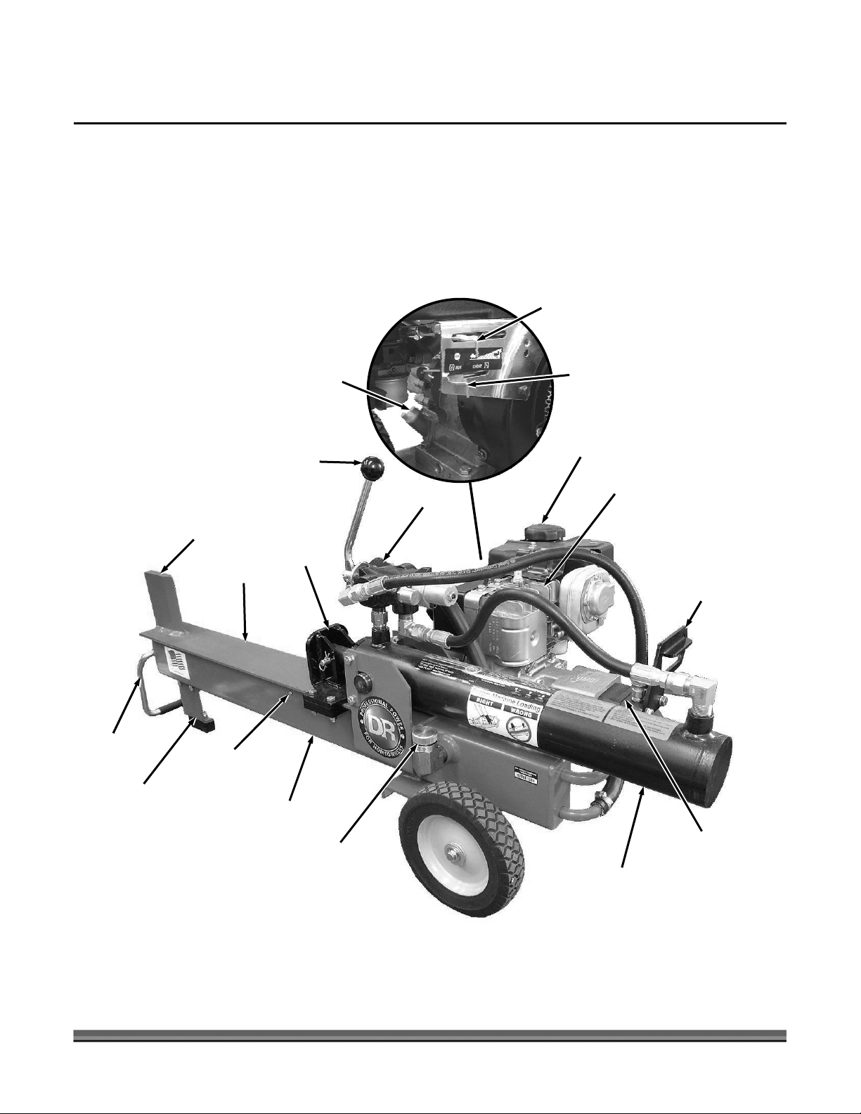
It may be helpful to familiarize yourself with the controls and features on your Splitter by reviewing the
picture in Figure 1 before beginning the steps outlined in this chapter.
8-Ton DR Wood Splitter Controls and Features
Engine Oil
Fill Cap
Valve
Control
Handle
Splitting
Wedge
Push
Plate
Rail
Throttle
Choke
Fuel Tank
Cap
Engine
Valve
Rear Lift
Handle
Front Lift
Handle
Front Leg
with Rubber
Foot
Hydraulic
Fluid Level
Screw
Hydraulic
Tank
Hydraulic Tank
Fill Cap
Hydraulic
Pump
Cylinder
Figure 1
Contact us at www.DRpower.com 9
Page 10

Tools needed:
y
y
• 10" crescent wrench
• Flathead Screwdriver
• 7/16" open-end wrenches
• 1/2" open-end wrenches
• Utility Knife
• Hammer
• Long-necked Funnel
• Tin Cutters
Supplies needed:
• Hydraulic fluid (see “Specifications”, page 2)
• Engine oil (see engine manual)
• General purpose grease
Shipping List
The following chart lists the parts that are shipped with the
8-TON DR WOOD SPLITTER.
DESCRIPTION
Base Unit (engine) 1
Cylinder and Push Plate Assembl
Parts Box Contents
Front Leg Assembl
Tire, 8" 2
Hardware Bag 1
Hardware Bag Contents
Bolt (5/16-18 x 1") 1
Bolt (5/16-18 x 3/4") 4
Nut, Push-on 2
Nut, Nylon Lock (5/16")
Plate, Cylinder Retainer 2
Washer, Flat (1/2") 4
Users Manual Bag Contents
Handle Assembly Kit (includes
Handle, Knob, Clevis Pins and
Hairpin Clips)
S & O Manual 1
Engine Users Manual 1
1
QTY
1
5
1
10 8-TON DR
®
WOOD SPLITTER
Page 11
Unpacking the Crate
WEAR EYE PROTECTION WHEN CUTTING THE BANDING.
THE BANDING MAY HAVE A LOT OF TENSION ON IT AND
MAY SNAP AND CUT YOU. ALWAYS STAND TO ONE SIDE
WHEN CUTTING THE BANDING.
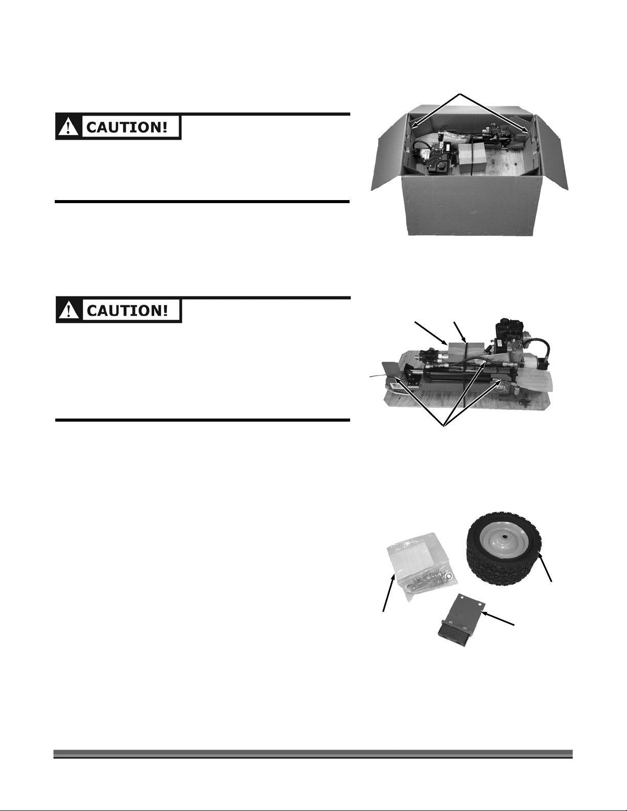
1. Cut the banding (tin cutters) and pull the box off the
pallet.
2. Cut the tape (utility knife) and open the box. Pull out
both Support Inserts (Figure 2).
THE WOOD SPLITTER WEIGHS APPROXIMATELY 140
LBS. WE RECOMMEND TWO PEOPLE FOR STEP 3.
BE CAREFUL WHEN WORKING NEAR THE SPLITTING
WEDGE. THE WEDGE CAN EASILY CUT OR PUNCTURE
THE SKIN IF YOU CONTACT IT AT THE POINTED TOP
CORNER OR SHARP FRONT EDGE.
Figure 2
Parts
Box
Support
Inserts
Plastic
Banding
3. With a person at each end of the box, lift the plywood
base that the Splitter is attached to, out of the box.
4. Cut the remaining banding strap and Cable Ties (tin
cutters) (Figure 3).
5. Open the Parts box, and make sure all the smaller
parts have been shipped (Figure 4). The chart in the
“Shipping List” (previous page) provides a complete
list of all the parts shipped with your Wood Splitter. If
you have any questions, please contact us at
www.DRpower.com or call DR Power Equipment at 1–
800-DR-OWNER (376-9637).
Figure 3
Hardware
Package
Figure 4
Cable
Ties
Two 8"
Tires
Front Leg
with Rubber
Foot
Contact us at www.DRpower.com 11
Page 12

Assembly Procedure
READ ALL INSTRUCTIONS AND SAFETY RECOMMENDATIONS BEFORE ASSEMBLING OR OPERATING
THIS WOOD SPLITTER.
Cylinder and
Push Plate
Assembly
Figure 5
Bolt and
Locknut
Trunnion
Pins
Securing the Cylinder and Push Plate Assembly
6. Slide the Cylinder and Push Plate Assembly towards
the Engine until the Trunnion Pins on the side of the
Cylinder fit into the slots of the Cylinder Mounting
Bracket (Figure 5).
Cylinder
Mounting
Bracket
7. Install the two Cylinder Retainer Plates using four 5/16
x 3/4 inch long Hex Bolts and Locknuts (Figure 6).
Tighten the Nuts securely (1/2 inch wrenches).
Cylinder
Retainer
Plate
Figure 6
High -Pressure
Hose
Figure 7
12 8-TON DR
®
WOOD SPLITTER
Low -Pressure
Hose
Hose
Clamp
8. Push the Low-Pressure Hose onto the Fitting (Figure
7).
9. Loosen the Hose Clamp (flathead screwdriver) and
slide it up over the end of the Low-Pressure Hose and
tighten.
10. Thread the High-Pressure Hose onto the Control
Valve Fitting and tighten (crescent wrench).
Page 13

Attaching the Valve Control Handle to the Valve
1. Install the Clevis Pin and Hairpin Clip through the
bottom hole on the Valve (Figure 8).
2. Insert the forked end of the Valve Control Handle over
the Clevis Pin.
3. Align the hole in the Handle with the top hole in the
Valve and insert the top Clevis Pin and Hairpin Clip.
4. Remove the Bolt and Locknut that is securing the
wedge end of the Splitter to the shipping Bracket
(1/2" wrenches) (Figure 9).
NOTE: Set the Bolt and Locknut that was removed in the last
step aside to be used when you install the Front Leg.
Valve
Control
Handle
Clevis
Pin
Figure 8
Hairpin
Clip
Clevis
Pin
Valve
Hairpin
Clip
Bolt and
Locknut
5.
Remove the Two Carriage Bolts and Locknuts that secure
the Shipping Bracket to the Plywood Base (1/2" wrenches)
and remove the Shipping Bracket (Figure 10).
6. Slide the Splitter out of the Shipping Bracket that is on the
opposite side and set the Splitter on a flat, clean surface.
Shipping
Bracket
Figure 9
Carriage
Bolts and
Locknuts
Figure 10
Shipping
Bracket
Contact us at www.DRpower.com 13
Page 14

Installing the Tires and Front Leg
1. Raise one side of the Wood Splitter and slide two
Large Washers over the Axle then install a Tire onto
the axle (Figure 11).
Axle
Figure 11
Figure 12
Front
Handle
Figure 13
2 Large
Washers
Push-on
Nut
Front
Leg
Tire
Rail
Bolts and
Locknuts
2. Install a Push-on Nut and tap it in place (hammer)
(Figure 12). Repeat the process for the other wheel.
NOTE: Placing a socket over the push nut and tapping on the socket
will make it easier to install the push nut.
3. Unfold the Front Handle from under the Rail (Figure
13).
4. Attach the Front Leg to the Rail using two 5/16" x 1"
Hex Bolts and Locknuts. One Bolt/Locknut is in the
parts box; the other you already removed from the Rail
and the Shipping Bracket.
Your 8-Ton DR Wood Splitter is now fully assembled.
14 8-TON DR
®
WOOD SPLITTER
Page 15

Start-Up Procedure
w
(
READ AND FOLLOW ALL OF THE INSTRUCTIONS IN THE “START-UP PROCEDURE” BEFORE STARTING
THE ENGINE AND OPERATING THE WOOD SPLITTER. FAILURE TO FOLLOW THIS RECOMMENDATION
WILL RESULT IN ENGINE AND HYDRAULIC PUMP DAMAGE.
BEFORE STARTING THE ENGINE, READ THE ENGINE MANUFACTURER’S OPERATING AND
MAINTENANCE INSTRUCTION MANUAL. IF YOU HAVE ANY QUESTIONS, PLEASE CONTACT US AT
WWW.DRPOWER.COM OR CALL OUR CUSTOMER SERVICE REPRESENTATIVES AT OUR TOLL-FREE
NUMBER: 1-800-DR-OWNER
NOTE: Place a clean container under Hydraulic Fluid
Overflow Screw to catch any overflow of Hydraulic
Fluid. Do not allow excess Fluid to spill onto the
ground.
1. Ensure that the Splitter is on a flat, level surface and
remove the Hydraulic Tank Cap and the Hydraulic
Fluid Overflow Screw from the Hydraulic Tank (Figure
14).
376-9637).
2. Using a long-neck funnel, slowly pour approximately
114 oz. (3.3 liters) of SAE 10W tractor hydraulic Fluid
or automatic transmission fluid, such as Dextron III,
into the hydraulic tank. Pour the fluid slowly, allowing
air to escape as you fill the tank.
3. When Fluid begins coming out of the Overflow Hole,
stop pouring and wait for the Fluid to stop flowing
from the hole. reinstall the Hydraulic Fluid Overflow
Screw.
4. Screw on the Hydraulic Tank Cap and hand tighten.
NOTE: The total hydraulic system fluid capacity is 154 oz.
(4.5 liters), but only add 114 oz. (3.3 liters) for now.
5. Lubricate the underside of the rail with grease (Figure
15). This will help to prevent wear between the Slide
Plates and the Rail.
Figure 14
Figure 15
Hydraulic
Fluid
Overflow
Scre
Underside
of Rail
Hydraulic
Tank Cap
Slide
Plate
Contact us at www.DRpower.com 15
Page 16

Crank Case
Fill Cap
Figure 16
6. Remove the Crank Case Fill Cap (Figure 16) and Fill
the engine’s crankcase with 20 ounces (approximately
2/3 of a quart) of the engine manufacturer’s
recommended oil. Pour slowly and fill to the point of
overflowing. You may want to use a long-neck funnel
to help reach the fill opening. 10W 30 is a general
purpose motor oil, however refer to the Oil Chart in
the engine manual for different viscosities and types to
use for different Starting temperatures.
7. Replace the Crank Case Fill Cap.
Gas Cap
Figure 17
BE CAREFUL NOT TO SPILL FUEL WHEN FILLING THE
ENGINE. IF FUEL SHOULD SPILL, QUICKLY WIPE OFF AND
ALLOW THE EXCESS FUEL TO EVAPORATE BEFORE
CONTINUING. FUEL AND FUEL VAPORS ARE HIGHLY
FLAMMABLE AND CAN CAUSE PERSONAL INJURY OR EVEN
DEATH WHEN IGNITED.
DO NOT MIX OIL WITH THE GASOLINE. USING MIXED
OIL/GASOLINE IN A FOUR CYCLE ENGINE CAN CAUSE
ENGINE DAMAGE.
8. Remove the Gas Cap (Figure 17) and fill the engine’s
fuel tank with fresh, clean, lead-free automotive
gasoline to approximately 1-1/2" below top of neck to
allow for expansion.
9. Replace the Gas Cap.
10. Move the throttle to FAST and the Choke Lever to
CHOKE (Figure 18).
Throttle
Choke
Lever
Figure 18
16 8-TON DR
Starter
Cord
®
WOOD SPLITTER
11. Pull the starter cord and start the engine.
12. Allow the engine to warm up, then adjust the choke
towards the RUN position until the engine runs
smoothly.
Page 17

KEEP ALL BODY PARTS AWAY FROM THE SLIDE AREA WHEN CYCLING THE CYLINDER.
13. Push the Valve Control Handle, with one hand, to the
forward (extend) position (towards the front of the
cylinder) (Figure 19).
14. When the Push Plate is fully extended, push the Valve
Control Handle to the retract position and retract the
Cylinder Piston (Figure 20). The Cylinder Valve will
automatically stop the Cylinder from retracting when it
reaches the end of its stroke. Fully cycle the Cylinder 2
to 3 times.
NOTE: Extending and retracting the cylinder piston draws the
hydraulic fluid through the system and expels any
trapped air from the system.
Valve
Control
Handle
Push
Plate
Figure 19
Valve
Control
Handle
Extend
Retract
Cylinder
Valve
15. Turn off the engine.
16. Remove the Hydraulic Fluid Overflow Screw from the
side of the Tank (Figure 21).
17. Remove the Hydraulic Tank Cap and slowly start
adding the remaining 40 oz. (1.2 liters) of Hydraulic
Fluid until Fluid comes out of the Overflow Screw
Hole. DO NOT OVERFILL THE HYDRAULIC TANK.
18. Wait until the Fluid stops flowing from the hole and
reinstall the Overflow Screw.
19. Screw on and tighten the Hydraulic Tank Cap.
20. Check all fittings and hoses for leaks and tighten as
needed.
Your 8-Ton DR Wood Splitter is now ready to use.
Figure 20
Hydraulic
Fluid
Overflow
Screw
Figure 21
Hydraulic
Tank
Contact us at www.DRpower.com 17
Hydraulic
Tank Cap
Fluid Fill
Elbow
Page 18

Chapter 3: Operating Your Wood Splitter
TOP VIEW
Operator
Zone
Figure 22
DO NOT ATTEMPT TO OPERATE THE WOOD SPLITTER
WITHOUT FULLY UNDERSTANDING ALL INSTRUCTIONS,
SAFETY PRECAUTIONS, AND/OR WARNINGS. IF ANY DOUBT
OR QUESTION ARISES ABOUT THE CORRECT OR SAFE
METHOD OF PERFORMING ANYTHING FOUND IN THIS
MANUAL, PLEASE CONTACT OUR CUSTOMER SERVICE
REPRESENTATIVES AT OUR TOLL FREE NUMBER: 1-800-DROWNER (376-9637).
WHEN OPERATING THE WOOD SPLITTER, MAKE SURE YOU
ARE IN THE SAFE OPERATING AREA (OPERATOR ZONE) AS
SHOWN IN FIGURE 22. YOU MUST STAY IN THE SAFE
OPERATING AREA AT ALL TIMES WHEN THE SPLITTING
WEDGE IS IN MOTION (WHETHER EXTENDING OR
RETRACTING). NEVER PLACE ANY PART OF YOUR BODY
INTO A POSITION THAT CAUSES AN UNSAFE OPERATING
CONDITION.
BEFORE LOADING AND OPERATING THE WOOD SPLITTER,
ALWAYS WEAR PROTECTIVE GEAR, INCLUDING SAFETY
GOGGLES, HEARING PROTECTION, TIGHT-FITTING GLOVES
WITHOUT DRAW STRINGS OR LOOSE CUFFS, AND STEELTOED SHOES.
Splitting
Wedge
Figure 23
18 8-TON DR
®
WOOD SPLITTER
Hands
on Sides
of Wood
USE THE FOLLOWING PHOTOS FOR THE CORRECT AND
INCORRECT METHODS OF SPLITTING LOGS. NEVER SPLIT A
LOG USING AN INCORRECT OR UNSAFE METHOD.
1. Set your Wood Splitter on flat, dry ground. Make sure
you read all the recommendations from the “General
Safety Rules” in Chapter 2 before using the Wood
Splitter.
2. Start the engine using the instructions from the engine
manual. If the Wood Splitter has not been running
(cold engine), warm up the engine and hydraulic
system by running the engine at half throttle for 3 to 4
minutes, then advance the engine throttle control to
maximum speed.
3. Place the log on the Wood Splitter. Grasp the log on
the sides near the middle of the block (Figure 23).
Center the log, side-to-side, on the rail of the Wood
Splitter, making sure that one end is against the
Splitting Wedge.
Page 19

J
DO NOT PLACE YOUR HANDS ON THE ENDS OF THE LOG
NDS
(FIGURE 24)
.
WHEN LOADING THE WOOD SPLITTER. THIS IS A VERY
UNSAFE METHOD AND COULD RESULT IN INJURY TO YOUR
HA
DO NOT REACH OR STEP ACROSS THE RAIL WHILE THE
WOOD SPLITTER IS RUNNING. THIS IS A VERY UNSAFE
METHOD WHICH COULD CAUSE PERSONAL INJURY OR
EVEN DEATH (FIGURE 25).
4. Make sure both ends of the log you are splitting are
cut as square as possible. This will prevent the log
from sliding out of position while under pressure. All
logs should be no longer than 18" (Figure 26).
NEVER ATTEMPT TO SPLIT WOOD ACROSS THE GRAIN. THE
WOOD SPLITTER WAS NOT DESIGNED FOR CROSS-GRAIN
SPLITTING. DOING SO WILL DAMAGE THE WOOD SPLITTER
AND MAY CAUSE PERSONAL IN
URY (FIGURE 27).
5. Using only your hand, push the Valve Control Handle
forward (towards the log) (Figure 28). If the log moves
before it is contacted by the Push Plate, release the
Valve Control Handle and then reposition the log.
Operate the Wood Splitter only when in the safe
operating area, as shown in Figure 22.
Figure 24
Figure 25
Figure 28
Figure 26
Valve
Control
Handle
Push Plate
Figure 27
Contact us at www.DRpower.com 19
Page 20

Figure 29
Push
Plate
Hold
Side
Valve
Control
Handle
IF YOU FIND YOU MUST HOLD THE LOG UNTIL THE PUSH
PLATE TOUCHES IT AND HOLDS IT IN PLACE, BE VERY
CAREFUL NOT TO PUT YOUR HAND BETWEEN THE LOG
AND THE PUSH PLATE OR THE LOG AND THE SPLITTING
WEDGE. IF YOU MUST, HOLD THE LOG FROM THE SIDE
AND IN THE MIDDLE (FIGURE 29). REMOVE YOUR HAND
IMMEDIATELY WHEN THE PUSH PLATE ENGAGES THE LOG.
NEVER USE YOUR KNEE OR ANY EXTENSION DEVICE TO
OPERATE THE VALVE CONTROL HANDLE.
6. Hold the Valve Control Handle, extending the Push
Plate (Figure 30), until the log is split or the cylinder
rod stops at its maximum travel position. Stop the
Wood Splitter (forward movement), at any point in the
splitting process, if you feel an unsafe splitting
condition is occurring. As the log is being split, DO
NOT reach forward and attempt to catch the split
wood — let it fall to the ground.
Figure 30
Figure 31
Push Plate
Valve
Control
Handle
7. Once the Push Plate reaches its full forward travel,
pull back on the Valve Control Handle to the full
retract position (Figure 31). The ram of the cylinder
will automatically retract into the cylinder.
20 8-TON DR
®
WOOD SPLITTER
Page 21

NOTE: It is not necessary to hold the Valve Control Handle as
J
the cylinder retracts (Figure 32). Stop the Push Plate
if the log sticks (see caution on next page). When the
Valve
Control
Handle
cylinder is fully retracted, the Control Valve will
automatically shift to a neutral position.
Control
Valve
Figure 32
DEPENDING ON THE TYPE OF WOOD BEING SPLIT, A LOG MAY NOT ALWAYS SPLIT INTO TWO
PIECES AND FALL TO THE GROUND. IF A LOG STICKS TO THE WEDGE OR PUSH PLATE, MOVE THE
VALVE CONTROL HANDLE IN THE CENTER (NEUTRAL) POSITION TO STOP THE PUSH PLATE FROM
RETRACTING, STOP THE ENGINE, AND CAREFULLY REMOVE THE LOG FROM THE WEDGE OR PUSH
PLATE. ALLOWING THE LOG TO REMAIN ATTACHED TO THE PUSH PLATE WHEN IT IS FULLY
RETRACTED COULD LEAD TO POSSIBLE IN
URY AND/OR DAMAGE TO THE WOOD SPLITTER.
8. DO NOT load another log or remove split pieces until the Push Plate has completely stopped and
the Valve Control Handle automatically returns to the neutral position.
Splitting Large Logs
When splitting a large log, or one in which the wood is
extremely tough or stringy (such as elm), the first pass
through the Splitter may not split the log into two sections.
If this happens, turn the log and split off small sections.
Repeat this process as necessary to split the entire log
(Figure 33).
Figure 33
Contact us at www.DRpower.com 21
Page 22

Chapter 4: Inspection And Maintenance
This chapter covers regular maintenance procedures that will ensure the best performance and long life
of your machine. For engine maintenance, please refer to the engine owner’s manual that came with
your Splitter. Service intervals listed in the check list below supercede those listed in the engine owner’s
manual.
Maintenance Kits and Accessories are available through our website at www.DRpower.com.
Regular Maintenance Check List
NOTE: Service intervals shown are considered maximum under normal operating conditions. Increase
frequencies under extremely dirty or dusty conditions.
Procedure
Check Hydraulic Fluid Level
Check Engine Oil Level
Check General Equipment Condition
Check Wedge for Sharpness
Grease Bottom Surface of Slide Rail
Clean Engine Exterior and Cooling Fins
Before Each Use Every 25 Hours Every 100 Hours
▲
▲
▲
▲
▲
▲
Change Engine Oil 1st time 5 hours
Replace Air Filter
Change Hydraulic Fluid
Replace Spark Plug
▲
▲
▲
▲
22 8-TON DR
®
WOOD SPLITTER
Page 23

General Maintenance Check (before operating)
The hydraulic system (hoses, cylinder, and pump) should be carefully inspected before each use. Also,
inspect the mechanical parts at the same time. Make sure all clamps, nuts, bolts, fittings, etc. are
properly installed and tightened.
DO NOT CHECK FOR LEAKS WITH YOUR HAND. LEAKS CAN BE LOCATED BY PASSING A PIECE OF
CARDBOARD OR WOOD AROUND THE SUSPECTED LEAK AND LOOKING FOR DISCOLORATION.
HIGH-PRESSURE FLUID ESCAPING FROM A VERY SMALL HOLE CAN BE ALMOST INVISIBLE. ESCAPING
FLUID UNDER PRESSURE CAN HAVE SUFFICIENT FORCE TO PENETRATE SKIN, CAUSING SERIOUS
INJURY OR EVEN DEATH. IF FLUID IS INJECTED INTO YOUR SKIN, IT MUST BE TREATED IMMEDIATELY
BY A DOCTOR FAMILIAR WITH THIS TYPE OF INJURY.
Always replace frayed, kinked, or cracked hoses and/or other damaged hydraulic components with DR
Power Equipments authorized parts and components specified in the “Parts” section (Chapter 8) of this
manual. Replacement parts from secondary suppliers (not original DR Power Equipments replacement
parts) can lead to product damage and/or personal injury, and will void the warranty.
DO NOT REMOVE THE CAP FROM THE HYDRAULIC TANK OR RESERVOIR WHILE THE WOOD
SPLITTER IS RUNNING. HOT FLUID, UNDER PRESSURE, COULD BE EXPELLED RESULTING IN SERIOUS
INJURY.
Should it become necessary to loosen or remove any hydraulic fitting or line, be sure to relieve all
hydraulic pressure by shutting off the engine, removing the spark plug wire, and moving the valve
control handle back and forth several times until no cylinder movement is visible.
Engine Service
Refer to the engine manufacturer’s manual for engine maintenance, repair and storage.
Rail Maintenance
Between each use of the WOOD SPLITTER, we recommend applying a rust preventative (Fluid Film or
equivalent) to any bare metal areas on the top of the rail. This will assure the longest possible service life
of the Slide Plates.
Contact us at www.DRpower.com 23
Page 24

Hydraulic Fluid Change
Tools needed:
• Flat Head Screwdriver
• Spark plug socket and Ratchet
1. Drain the hydraulic tank.
a. Place a waste fluid container under the inlet hose.
b. Loosen the Hose Clamp on the end of the inlet hose
(Flat Head Screwdriver) (Figure 34).
c. Remove the Inlet Hose from the Tank.
d. Completely drain the Tank.
e. Reconnect the Inlet Hose to the Tank.
Figure 34
Figure 35
Hose
Clamp
Hose
Clamp
Inlet
Hose
Return
Hose
f. Tighten the Hose Clamp on the end of the Inlet Hose
(Flat Head Screwdriver).
2. Drain the head end of the cylinder.
a. Remove the spark plug wire and spark plug to help
reduce the back pressure on the engine and to prevent
it from starting.
NOTE: The total amount of hydraulic fluid in the system is 1.5
gallons.
b. Loosen the Hose Clamp on the end of the Return
Hose (Figure 35)
c. Disconnect the Return Hose (low pressure) from the
Hydraulic Tank and direct it into a waste fluid
container. (Please properly dispose of the waste
hydraulic fluid per local regulations.)
d. Extend the cylinder by holding the Valve Control
Handle forward and pulling on the engine’s pull start
cord until fluid from the return line stops flowing. This
step drains the head end of the cylinder.
24 8-TON DR
®
WOOD SPLITTER
e. Do not replace the Return Hose at this time.
Page 25

DO NOT MIX TRACTOR HYDRAULIC FLUID WITH TRANSMISSION FLUID. USE ONE OR THE OTHER.
3. Refill the hydraulic tank.
a. Remove the Hydraulic Tank Cap and the Hydraulic
Fluid Overflow Screw from the Hydraulic Tank (Figure
36).
b. Using a long-neck funnel, slowly pour approximately
114 oz. (3.3 liters) of SAE 10W tractor hydraulic Fluid
or automatic transmission fluid, such as Dextron III,
into the hydraulic tank. Pour the fluid slowly, allowing
air to escape as you fill the tank.
c. When Fluid begins coming out of the Overflow Hole,
stop pouring and wait for the Fluid to stop flowing
from the hole. reinstall the Hydraulic Fluid Overflow
Screw.
d. Screw on the Hydraulic Tank Cap and hand tighten
Hydraulic
Fluid
Overflow
Screw
Figure 36
Hydraulic
Tank
Hydraulic
Tank Cap
Fluid Fill
Elbow
4. Drain and refill the piston end of the cylinder.
a. Hold the Valve Control Handle in the retract position
and pull the engine pull start cord until the cylinder rod is fully retracted. This step removes the old
fluid from the piston end of the cylinder.
b. Reconnect the Return Hose to the Hydraulic Tank (Figure 35).
c. Extend the cylinder by holding the Valve Control Handle forward and pulling on the engine’s pull
start cord until the cylinder is completely extended. This step refills the piston end of the cylinder.
5. Start the engine and cycle the cylinder.
a. Replace the spark plug and spark plug wire.
b. Start the engine and cycle the cylinder several times (see “Operating Your Wood Splitter”, Chapter
4).
c. Retract the cylinder and shut off the engine.
d. Recheck the Hydraulic Tank to make sure fluid is up to the Hydraulic Fluid Overflow Screw.
Hydraulic Fluid Specifications
Above 30˚ F . . . . . . . . . AW-32, 10W (non-foaming) or ATF DEXTRON III
Below 30˚ F . . . . . . . . . use only ATF DEXTRON III
Hydraulic Fluid Capacities
Hydraulic System (including cylinder, tank, and hoses) . . . . . . . 154 oz. (4.5 liters)
Contact us at www.DRpower.com 25
Page 26

End of Season and Storage
BEFORE PERFORMING ANY MAINTENANCE PROCEDURE, STOP THE ENGINE AND
DISCONNECT THE SPARK PLUG WIRE.
NOTE: Please refer to the engine owner's manual for engine-specific procedures.
• Change the engine oil.
• Remove the spark plug and pour about 1 ounce of motor oil into the cylinder hole. Replace the plug
and pull the recoil starter rope until you feel strong resistance. This will coat the piston and seat the
valves to prevent moisture buildup.
• Clean/replace the air filter.
• Clean dirt and debris from the cylinder head cooling fins and muffler area of the engine.
• If your 8-TON DR WOOD SPLITTER will be idle for more than 30 days, we recommend using a gas
stabilizer. This will prevent sediment from gumming up the carburetor. If there is dirt or moisture in
the gas or tank, remove it by draining the tank. Completely fill the tank with fresh, unleaded gas and
add the appropriate amount of stabilizer or gasoline additive. Run the engine for a short time to
allow the additive to circulate. Close the fuel shut-off valve to prevent carburetor overflow and
leakage.
• Check the wedge for nicks and wear. Sharpen if needed.
• Apply Fluid Film to areas where the paint has worn or chipped off to bare metal.
• If possible, store the unit inside or cover it completely if stored outside.
• Grease bottom surface of Slide Rail.
26 8-TON DR
®
WOOD SPLITTER
Page 27

Chapter 5: Troubleshooting
Most problems are easy to fix. Consult the troubleshooting table for common problems and their
solutions. If you continue to experience problems contact us at www.DRpower.com or call DR Power
Equipment Toll Free at 1-800-DR-OWNER (376-9637) for support.
BEFORE PERFORMING ANY MAINTENANCE PROCEDURE, STOP THE ENGINE AND
DISCONNECT THE SPARK PLUG WIRE.
Troubleshooting Table
SYMPTOM POSSIBLE CAUSE
When the valve
control handle is
pushed forward
(extend), the push
plate does not
move.
⇒ Check the hydraulic tank to make sure the fluid level is up to the hydraulic fluid
overflow screw hole. If the fluid is not up to the overflow hole, fill with hydraulic
fluid until it is up to the overflow hole.
⇒ If the fluid level is OK then contact us at www.DRpower.com or call 1 (800) DR-
OWNER (376-9637) for assistance.
The engine won’t
start.
(Please refer to the
engine owner’s
manual for enginespecific procedures.)
The engine lacks
power or is not
running smoothly.
(Please refer to the
engine owner’s
manual for enginespecific procedures.)
⇒ Are you using fresh, clean gas? If the gas is old, change it. Use a fuel stabilizer if
you keep gas longer than 30 days.
⇒ Is the spark plug clean? If the spark plug is dirty or cracked, change it. If it’s oily,
leave it out, hold a rag over the plug hole and pull the recoil cord several times to
blow out any oil in the cylinder, then wipe off the plug and reinsert it.
⇒ If your engine still won’t start, contact us at www.DRpower.com or call 1(800) DR-
OWNER (376-9637) for assistance.
⇒ Check that the Throttle Lever is in the “Run” position.
⇒ Is the air filter clean? If it’s dirty, change it following the procedure in the engine
manufacturer’s owner’s manual.
⇒ Is the spark plug clean? If it’s fouled or cracked, change it. If it’s oily, leave it out,
hold a rag over the plug hole and pull your recoil cord several times to blow out
any oil in the cylinder, then wipe off the plug and reinsert it.
⇒ Are you using fresh, clean unleaded gas? If it’s old, change it. Use a fuel stabilizer
if you keep gas longer than 30 days.
⇒ Does your engine have the right amount of clean oil? If it’s dirty, change it
following the procedure in the engine manufacturer’s owner’s manual.
⇒ Check the oil level and adjust as needed.
⇒ If your engine still lacks power, contact us at www.DRpower.com or call 1(800)
DR-OWNER (376-9637) for assistance.
Contact us at www.DRpower.com 27
Page 28

SYMPTOM POSSIBLE CAUSE
Engine smokes.
(Please refer to the
engine owner’s
manual for enginespecific procedures.)
⇒ Check the oil level and adjust as needed.
⇒ Check the air filter and clean or replace if needed.
⇒ You may be using the wrong oil—too light for the temperature. Refer to your
Engine Owner’s Manual for detailed information.
⇒ Clean the cooling fins if they’re dirty.
⇒ If the engine still smokes, contact us at www.DRpower.com or call 1(800) DR-
OWNER (376-9637) for assistance.
The engine stalls
when the push plate
engages the wood.
The pusher plate
moves slowly, but
will split wood.
The ram will not
automatically
retract.
Hydraulic fluid
squirts from the fill
plug during
operation.
⇒ The engine may not be properly adjusted. Contact us at www.DRpower.com or call
1(800) DR-OWNER (376-9637) for assistance.
⇒ Check the hydraulic fluid level in the hydraulic tank and fill if necessary.
⇒ Check the high-pressure hose, fittings, and valve openings for dirt and debris that
may have obstructed the openings.
⇒ Check the slide rail or push plate for damage.
⇒ Push the valve control handle to the retract position. If the handle will not stay in
this position, contact us at www.DRpower.com or call 1(800) DR-OWNER (376-
9637) for assistance.
⇒ The hydraulic fluid tank may be over-filled. Drain fluid down to the overflow screw.
⇒ The WOOD SPLITTER is not level. Make sure the WOOD SPLITTER is on level
ground.
28 8-TON DR
®
WOOD SPLITTER
Page 29

Chapter 6: Class II Receiver Mount Accessory
The Receiver Mount Accessory mounts to your 8-Ton DR
Wood Splitter so that it can be installed on a vehicle with a
Class II 2" x 2" Trailer Hitch Receiver. This is a convenient
and efficient way to transport your Wood Splitter to the job
site for two reasons:
a. It provides a handy operating position from the
back of your vehicle.
b. It allows more space in your vehicle for hauling
split firewood.
1. Position your Wood Splitter so you can easily access
the underside of the engine mount.
2. Unpack all parts from the shipping box and place the
Receiver Attachment Bracket in the orientation shown
(Figure 37). (the bracket will be mounted under the
frame of the Wood Splitter using the same bolts that
hold the engine in place.)
3. Reach under the frame of your Wood Splitter and use
a 1/2" wrench to remove the Hex Nuts, Lock Washers,
and Flat Washers from the Engine Mount Bolts. Leave
the Bolts in place.
4. Position the Receiver Attachment Bracket under the
frame. Align the holes in the Bracket over the ends of
the exposed Engine Mount Bolts and install Flat
Washers, Lock Washers, and Hex Nuts. Tighten
securely.
5. Make sure you remove the Clip and Clevis Pin from
the adjustable Receiver Bar (Figure 38), then insert the
long straight end
of the Bar into the Bracket (Figure
39).
Engine
Mount
Hardware
Figure 37
Figure 38
Receiver
Attachment
Bracket
Clevis
Pin
Receiver
Bar
Clip
NOTE: The end of the Receiver Bar should just go through the
other side of the Receiver Attachment Bracket to have
room to install the Clevis Pin and Clip.
6. Insert Clevis Pin and Clip into the end of the Receiver
Bar.
7. Screw the L-Shaped Tensioning Bolt into the threaded
hole in the Receiver Attachment Bracket and tighten
by hand.
Figure 39
Clevis Pin
and Clip
Receiver
Receiver
Bar
Contact us at www.DRpower.com 29
Attachment
Bracket
L-Shaped
Tensioning
Bolt
Page 30

Receiver
Hitch
Figure 40
Receiver
Bar
Vehicle
Hitch
High Position
Receiver
Bar
Low Position
8. Position the Wood Splitter behind the vehicle with the
engine of your Wood Splitter on the right-hand side
(Figure 40).
NOTE: The end of the Receiver Bar that inserts into your vehicle
hitch features a dual-height positioner. By turning the Bar 180˚ (up
or down) in the vehicle hitch, your Wood Splitter can be oriented in
a high or low position (Figure 41). Use the HIGH position when
transporting your Wood Splitter, and use either the HIGH or LOW
position when splitting wood.
Figure 41
Class ll
Receiver
Figure 42
THE WOOD SPLITTER WITH THE RECEIVER MOUNT
ACCESSORY WEIGHS APPROXIMATELY 160 LBS. WE
RECOMMEND TWO PEOPLE FOR THIS NEXT OPERATION.
9. Lift the end of the Receiver Bar and start it into the
Vehicle Hitch (Figure 42).
Receiver
Bar
30 8-TON DR
®
WOOD SPLITTER
Page 31

10. Pick up your Wood Splitter up and slide the unit
forward into the Vehicle Hitch until the Lock Pin holes
line up (Figure 43). (Due to the weight, we
recommend two people for this operation). Lock the
Receiver Bar into position with your Vehicle Hitch
Lock Pin.
Vehicle Hitch
Lock Pin
Figure 43
NOTE: When you have the Wood Splitter adjusted to the end
of the Receiver Bar (with the Clevis Pin and Clip
installed at the end of the Receiver Bar and the LShaped Tensioning Bolt is hand tight) you will have
room to drop down the tailgate of the vehicle for easy
loading (Figure 44). This is the operating position.
The Wood Splitter should be secured in a stable and
level position for best splitting performance. When
positioning a heavy log on the Wood Splitter, it may
be necessary to support the Front Leg to maintain a
level position.
NOTE: When transporting your Wood Splitter, be sure to
carry it in the HIGH position (Figure 41) and slide it
as close to your vehicle as possible without hitting any
part of the vehicle. Secure it in position by hand
tightening the L-Shaped Tensioning Bolt (Figure 45).
Always be sure to have the Clevis Pin and Clip
inserted into the end of the Receiver Bar.
Vehicle Hitch
Lock Pin
Figure 44
L-Shaped
Tensioning
Bolt
Operating
Position
Clevis Pin
and Clip
Transport
Position
Observe the posted speed limits when transporting the
Wood Splitter with the receiver mount properly
installed and the Wood Slitter properly attached.
When traveling over rough terrain, drive slowly to
prevent undue stress to the Receiver Bar.
Figure 45
L-Shaped
Tensioning
Bolt
Contact us at www.DRpower.com 31
Clevis Pin
and Clip
Page 32

Chapter 7: Parts Lists, Schematic Diagrams And Warranty
Parts List and Schematic – Base Unit
NOTE: Part numbers listed are available through DR Power Equipment
Ref# Part# Description
1 235571 Rail Weldment
2 235581 Nut, Push-On, 1/2"
3 235591 Handle
4 235601 Black Grip, 1/2" diameter
5 235611 Front Leg
6 235621 Bolt, 5/16-18 x 1"
7 235631 Locknut, 5/16-18
8 235641 Pan head Screw, 1/4-20 x 1"
9 235651 Locknut, 1/4-20
10 235661 Bolt, 5/16-18 x 1-1/2"
11 235671 Slide Weldment
12 235681 Slide Guide Plate
13 235691 Slide Retainer Plate
Ref# Part# Description
14 235701 Lock Washer, 5/16"
15 235711 Nut, 5/16-18
16 235721 Clevis Pin, 3/8 x 2-1/2"
17 235731 Hairpin Clip, 3/32 x 1-5/8"
18 235741 Bolt, 5/16-18 x 3/4"
19 235751 Cylinder Retainer Plate
20 235761 Vented Fill Plug
21 235771 O-ring for Vented Plug
22 235781 Vented Fill Plug Breather
23 237911 Fitting, Street Elbow
24 237921 Tire, 8"
25 237931 Rubber Foot
26 265951 Screw, Hydraulic Fluid Overflow
32 8-TON DR
®
WOOD SPLITTER
Page 33

Parts List and Schematic – Pump and Piston Assembly
NOTE: Part numbers listed are available through DR Power Equipment
Ref# Part# Description
1 237951 Engine, Briggs, 4.75 ft. lbs. Torque
2 237961 Bolt, 5/16-18 x 1-3/4”
3 237971 Washer, 5/16"
4 237981 Lock Washer, 5/16”
5 237991 Nut, 5/16-18
6 238001 Square Key, 3/16”
7 238011 Set Screw, 1/4-20 x 1/2”
8 238021 Engine Coupling
9 238031 Spider
10 238041 Pump Coupling
11 238051 Engine Flange
12 238061 Pump Key
13 238071 Bolt, 5/16-24 x 3/4”
14 238081 Hydraulic Pump
15 238091 Bolt, 5/16-24 x 3-1/2”
16 238101 High-Pressure Hose
(pump to side of valve)
17 238111 Elbow , 90 Degree
Ref# Part# Description
18 238121 Hose Clamp, 5/8”
19 238131 Low-Pressure Hose 5/8” x 5”
20 238141 Low-Pressure Hose 5/8” x 15”
21 238151 Cylinder, 3” x 18”
22 238161 Elbow, 90 Degree
23 238171 High-Pressure Hose (cylinder to
bottom of valve)
24 238181 Elbow, 90 Degree
25 238191 Valve
26 238201 Handle Assembly Kit (includes
handle, clevis pins, and hairpin
clips)
27 238211 Straight Fitting
28 265961 Handle, Rear
Safety & Information Labels (not shown)
238221 Label, Operator Safety
265941 Label, Proper Machine Loading
Contact Us At www.DRpower.com 37
Page 34

Parts List and Schematic – Class II Receiver Hitch Accessory
NOTE: Part numbers listed are available through DR Power Equipment
1 240261 Bracket, Receiver Attachment
2 240271 Bar, Receiver
3 240281 Bolt, Tensioning, L-Shaped
4 240291 Pin, Clevis
5 240301 Clip
38 8-TON DR
®
WOOD SPLITTER
Page 35

8-TON DR® WOOD SPLITTER
2-Year Limited Warranty
The 8-TON DR
to ordinary and normal consumer use; ninety (90) days for any other use. The engine manufacturer warrants the engine
separately.
For the purposes of all the above warranties, “ordinary and normal consumer use” refers to non-commercial residential
use and does not include misuse, accidents or damage due to inadequate maintenance.
DR Power Equipment certifies that the 8-TON DR
this type is used. DR Power Equipment however, limits the implied warranties of merchantability and fitness in duration
to a period of two (2) year in consumer use, ninety (90) days for any other use.
The 2-Year Limited Warranty on the 8-TON DR
factory. The 2-Year Limited Warranty is applicable only to the original owner.
The warranty holder is responsible for the performance of the required maintenance as defined by the manufacturer's
owner's manuals. The warranty holder is responsible for replacement of normally wearing parts such as the air filter,
spark plug, and tires. Attachments and accessories to the machine are not covered by this warranty.
During the warranty period, the warranty holder is responsible for the machine transportation charges, if required.
During the warranty period, warranty parts will be shipped by standard method at no charge to the warranty holder.
Expedited shipping of warranty parts is the responsibility of the warranty holder.
SOME STATES DO NOT ALLOW LIMITATIONS ON THE LENGTH OF IMPLIED WARRANTIES, SO THE ABOVE
LIMITATIONS MAY NOT APPLY TO YOU.
DR Power Equipment shall not be liable under any circumstances for any incidental or consequential damages or
expenses of any kind, including, but not limited to, cost of equipment rentals, loss of profit, or cost of hiring services to
perform tasks normally performed by the 8-TON DR
®
WOOD SPLITTER is warranted for two (2) year against defects in materials or workmanship when put
®
WOOD SPLITTER is fit for ordinary purposes for which a product of
®
WOOD SPLITTER starts on the date the machine ships from our
®
WOOD SPLITTER.
Terms and Conditions
SOME STATES DO NOT ALLOW THE EXCLUSION OR LIMITATION OF INCIDENTAL OR CONSEQUENTIAL
DAMAGES, SO THE ABOVE LIMITATIONS MAY NOT APPLY TO YOU.
THIS WARRANTY GIVES YOU SPECIFIC LEGAL RIGHTS, AND YOU ALSO HAVE OTHER RIGHTS, WHICH VARY
FROM STATE TO STATE.
Warranty
Page 36

Daily Checklist for the 8-TON DR WOOD SPLITTER
To help maintain your 8-TON DR WOOD SPLITTER for optimum performance, we recommend you
follow this checklist each time you use your machine.
[ ] OIL: With the machine on a level surface, check the engine oil level with the dipstick and add more if
necessary (only add oil to the level indicated on the dipstick - DO NOT OVERFILL). Use SAE 10W
30 high detergent motor oil.
[ ] GAS: Fill the gas tank with clean, fresh, unleaded gasoline.
[ ] HYDRAULIC FLUID: Check hydraulic fluid level and fill as needed.
[ ] HYDRAULIC HOSES: Check hydraulic hoses for cracks or wear.
[ ] ENGINE AIR COOLING SYSTEM: It is very important to keep the engine clean of debris. Remove wood
chips and other built-up materials from the air intake screen before, during and after you run the
Splitter. Regularly remove debris from the cooling fins. A dirty engine retains heat and can cause
damage to the internal engine parts.
[ ] WEDGE: Check the wedge for tightness, nicks and wear.
[ ] GENERAL CONDITION: Check the general condition of the machine ( e.g.; nuts, bolts, welds etc.).
[ ] SLIDE RAIL: Apply a rust preventative (Fluid Film or equivalent) to any bare metal areas on the top of the
rail. This will assure the longest possible service life of the wear pads.
DR POWER EQUIPMENT
MEIGS ROAD, P.O. BOX 25, VERGENNES, VERMONT 05491
1-800-DR-OWNER (376-9637) • www.DRpower.com ©2009 CHP, Inc. 235491A
 Loading...