

Page 1

DR® 22-TON VERTICAL/HORIZONTAL
WOOD SPLITTER
SAFETY & OPERATING INSTRUCTIONS
DR Power Equipment
Serial No.
Order No.
READ AND UNDERSTAND THIS MANUAL AND ALL INSTRUCTIONS BEFORE OPERATING THIS 22-TON
VERTICAL/HORIZONTAL WOOD SPLITTER.
Toll-free phone: 1-800-DR-OWNER (376-9637)
Fax: 1-802-877-1213
Website: www.DRpower.com
Page 2

Table of Contents
Chapter 1: General Safety Rules..........................................................................................................4
Chapter 2: Setting Up Your DR 22-Ton Vertical/Horizontal Wood Splitter ....................................11
Chapter 3: Operating Your Wood Splitter.........................................................................................23
Chapter 4: Inspection And Maintenance .......................................................................................... 31
Chapter 5: Troubleshooting...............................................................................................................36
Chapter 6: Parts Lists, Schematic Diagrams And Warranty............................................................. 38
Conventions used in this manual
THIS INDICATES A HAZARDOUS SITUATION, WHICH, IF NOT AVOIDED, COULD RESULT IN DEATH
OR SERIOUS INJURY.
THIS INDICATES A HAZARDOUS SITUATION, WHICH, IF NOT AVOIDED, COULD RESULT IN MINOR
OR MODERATE INJURY.
THIS INFORMATION IS IMPORTANT IN THE PROPER USE OF YOUR MACHINE. FAILURE TO FOLLOW
THIS INSTRUCTION COULD RESULT IN DAMAGE TO YOUR MACHINE OR PROPERTY.
Serial Number and Order Number
A Serial Number is used to identify your machine and is located on the Serial Number Label on your
machine. An Order Number is used to check and maintain your order history and is located on the
upper left portion of your packing slip. For your convenience and ready reference, enter the Serial
Number and Order Number in the space provided on the front cover of this manual.
Additional Information and Potential Changes
DR Power Equipment reserves the right to discontinue, change, and improve its products at any time
without notice or obligation to the purchaser. The descriptions and specifications contained in this
manual were in effect at printing. Equipment described within this manual may be optional. Some
illustrations may not be applicable to your machine.
2 DR
®
22-TON VERTICAL/HORIZONTAL WOOD SPLITTER
Page 3

Specifications
MECHANICAL SPECIFICATIONS
Beam . . . . . . . . . . . . . . . . . . . . Heavy-duty 6 inch H-Beam
Wedge . . . . . . . . . . . . . . . . . . . 6 inch high-carbon steel (replaceable)
Force/Tonnage . . . . . . . . . . . . 22 ton
Cylinder Stroke . . . . . . . . . . . . 24 inches
Log Opening . . . . . . . . . . . . . . 25 inch maximum
Cycle Time . . . . . . . . . . . . . . . .12 seconds (approx.)
Operating Positions . . . . . . . . .Vertical/Horizontal
Wheels & Tires . . . . . . . . . . . . .High-Speed, 4.80 x 4.00 x 8"
Safety Chains . . . . . . . . . . . . . . Standard
Hitch Coupler . . . . . . . . . . . . . .2 inch locking ball (standard)
Engine . . . . . . . . . . . . . . . . . . . .Briggs and Stratton OHV horizontal shaft engine
HYDRAULIC SPECIFICATIONS
Cylinder Size . . . . . . . . . . . . . . . 4" x 24" clevis type cylinder, 1.75" rod
Hydraulic Tank . . . . . . . . . . . . . 7.5 gallon capacity
Hydraulic System . . . . . . . . . . . 9.5 gallon capacity (including tank, cylinder, hoses, filter)
Hydraulic Fluid Filter . . . . . . . . Spin-on type, 60 micron filter
Safety Release Control Valve . . Detent, auto return
Gear Pump . . . . . . . . . . . . . . . . 2-stage, 11 GPM
Control Valve . . . . . . . . . . . . . . .Auto Return
Hydraulic Fluid
Above 30° F . . . . . . . . . . . . . . . . Use AW-32, 10W (non foaming) or ATF Dextron III
Below 30° F . . . . . . . . . . . . . . . . Use only ATF Dextron III
SHIPPING SPACIFICATIONS
Shipping Weight . . . . . . . . . . . . 630 LBS
Contact us at www.DRpower.com 3
Page 4

Chapter 1: General Safety Rules
TO AVOID PERSONAL INJURY OR DEATH, CAREFULLY READ AND UNDERSTAND ALL INSTRUCTIONS
PERTAINING TO THE DR 22-TON VERTICAL/HORIZONTAL WOOD SPLITTER.
DO NOT ATTEMPT TO ASSEMBLE, OPERATE, OR MAINTAIN OUR PRODUCT WITHOUT FULLY
UNDERSTANDING ALL OUR INSTRUCTIONS AND SAFETY PRECAUTIONS. DO NOT OPERATE THE
WOOD SPLITTER UNLESS YOU READ AND UNDERSTAND THE INSTRUCTIONS AND WARNINGS IN
THIS MANUAL. IF YOU ARE EVER UNSURE ABOUT AN ACTION YOU ARE ABOUT TO TAKE, DON’T DO
IT. CONTACT DR POWER EQUIPMENT’ TOLL-FREE SUPPORT AT 1-800-DR-OWNER (376-9637) FOR HELP
OR INFORMATION.
ACCIDENTS CAN OFTEN BE AVOIDED BY BEING ALERT AND RECOGNIZING POTENTIALLY
HAZARDOUS SITUATIONS. ANY INDIVIDUALS OPERATING, MAINTAINING, OR REPAIRING PRODUCTS
MANUFACTURED BY DR POWER EQUIPMENT SHOULD HAVE THE NECESSARY TRAINING, SKILLS, AND
TOOLS REQUIRED TO PERFORM THESE FUNCTIONS PROPERLY AND SAFELY. THE SAFETY
INFORMATION IN THIS MANUAL SERVES AS A BASIC GUIDE IN AN ATTEMPT TO PREVENT INJURY OR
DEATH.
DR POWER EQUIPMENT CANNOT ANTICIPATE EVERY POSSIBLE CIRCUMSTANCE THAT MIGHT
INVOLVE A POTENTIAL HAZARD. THE WARNINGS IN THIS MANUAL AND ON THE PRODUCT ITSELF
ARE, THEREFORE, NOT ALL INCLUSIVE. IF TOOLS, PROCEDURES, WORK METHODS, OR OPERATING
TECHNIQUES THAT ARE NOT SPECIFICALLY MENTIONED BY DR POWER EQUIPMENT ARE USED, YOU
MUST SATISFY YOURSELF THAT THEY ARE SAFE FOR YOU AND FOR OTHERS. MAKE SURE THE WOOD
SPLITTER WILL NOT BE DAMAGED OR MADE UNSAFE BY ANY OPERATION, LUBRICATION,
MAINTENANCE, OR REPAIR PROCEDURES THAT YOU CHOOSE.
4 DR
®
22-TON VERTICAL/HORIZONTAL WOOD SPLITTER
Page 5
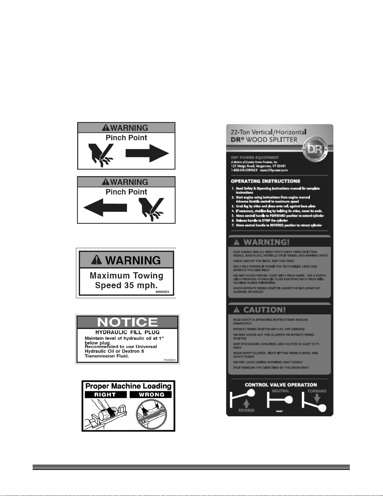
Labels
Your DR 22-TON VERTICAL/HORIZONTAL WOOD SPLITTER carries prominent labels as reminders for
its proper and safe use. Shown below are copies of all the labels that appear on the equipment. Take a
moment to study them and make a note of their location on your DR 22-TON VERTICAL/HORIZONTAL
WOOD SPLITTER as you assemble and before you operate the unit. Replace damaged or missing safety
and information labels immediately.
230591
(Set of two)
230611
230621
265941
230601
Contact us at www.DRpower.com 5
Page 6

Personal Protection
• TO AVOID PERSONAL INJURY OR DEATH, CAREFULLY READ AND UNDERSTAND ALL
INSTRUCTIONS PERTAINING TO THE WOOD SPLITTER INCLUDING THE ENGINE
MANUFACTURER’S OPERATING AND MAINTENANCE INSTRUCTION MANUAL.
• ALWAYS WEAR PROTECTIVE GEAR, SUCH AS SAFETY GOGGLES, TIGHT-FITTING GLOVES
WITHOUT DRAW STRINGS OR LOOSE CUFFS, STEEL-TOED SHOES, AND A PROTECTIVE HEARING
DEVICE.
• TO PREVENT INJURY, MAKE SURE ALL DECALS ARE ATTACHED TO THE WOOD SPLITTER AND
ARE LEGIBLE AT ALL TIMES.
Worksite Safety
• TO AVOID TRIPPING, DO NOT LEAVE TOOLS, LOGS, OR OTHER ITEMS LAYING AROUND THE
WORK AREA.
• NEVER OPERATE YOUR WOOD SPLITTER ON SLIPPERY, WET, MUDDY, OR ICY SURFACES. THE
LOCATION YOU CHOOSE SHOULD BE SOLID, LEVEL, DRY, AND FREE FROM ANY TALL GRASS,
BRUSH, OR OTHER INTERFERENCES.
• NEVER OPERATE THE ENGINE IN AN ENCLOSED AREA. EXHAUST FUMES CONTAIN CARBON
MONOXIDE THAT CAN BE DEADLY WHEN INHALED. MAKE SURE THE AREA IS WELL
VENTILATED.
• NEVER ATTEMPT TO MOVE YOUR WOOD SPLITTER OVER HILLY OR UNEVEN TERRAIN WITHOUT
A TOW VEHICLE.
• NEVER USE YOUR WOOD SPLITTER AT NIGHT.
• ALWAYS BLOCK THE WHEELS TO PREVENT MOVEMENT OF THE MACHINE WHILE IN
OPERATION.
Operating Safety
• ALLOW ONLY ONE (1) PERSON TO LOAD AND OPERATE THE WOOD SPLITTER.
• ALLOW ONLY ADULTS TO OPERATE THE WOOD SPLITTER. NO ONE UNDER THE AGE OF 18
SHOULD BE ALLOWED TO OPERATE THE WOOD SPLITTER.
6 DR
®
22-TON VERTICAL/HORIZONTAL WOOD SPLITTER
Page 7

• ALWAYS KEEP BYSTANDERS, INCLUDING CHILDREN AND PETS, AT LEAST TWENTY-FIVE (25)
FEET AWAY FROM THE WORK AREA. ONLY THE OPERATOR SHOULD STAND NEAR THE
EQUIPMENT AND ONLY WITHIN THE SAFE OPERATING AREA PRESCRIBED IN THIS MANUAL
(SEE THE PHOTOS ON SAFE AND UNSAFE OPERATING ZONES IN THE “OPERATING YOUR
WOOD SPLITTER” SECTION IN CHAPTER 4.)
• WHEN THE RAM OF THE WOOD SPLITTER IS IN THE RETURN MODE, KEEP YOUR HANDS OFF
THE MACHINE — THE WOOD SPLITTER IS DESIGNED TO AUTOMATICALLY STOP THE RAM
WHEN THE CYLINDER IS FULLY RETRACTED.
• ALWAYS DISCONNECT THE SPARK PLUG WIRE WHEN THE WOOD SPLITTER IS NOT IN
OPERATION.
• DO NOT ALLOW ANY PERSON TO OPERATE THE WOOD SPLITTER UNTIL THEY HAVE READ
AND UNDERSTOOD THE SAFE OPERATING INSTRUCTIONS CONTAINED IN THIS MANUAL.
• DO NOT, UNDER ANY CIRCUMSTANCES, ALTER YOUR WOOD SPLITTER. THIS EQUIPMENT
WAS DESIGNED AND ENGINEERED TO BE USED IN ACCORDANCE WITH THE OPERATING
INSTRUCTIONS. ALTERING THE EQUIPMENT, OR USING THE EQUIPMENT IN SUCH A WAY AS
TO CIRCUMVENT ITS DESIGN CAPABILITIES AND CAPACITIES, COULD RESULT IN SERIOUS OR
FATAL INJURY AND WILL VOID THE WARRANTY.
• NEVER OPERATE, OR ALLOW ANYONE ELSE TO OPERATE, THIS EQUIPMENT WHILE UNDER
THE INFLUENCE OF MEDICATION, DRUGS, OR ALCOHOL.
• NEVER WEAR LOOSE CLOTHING OR JEWELRY THAT MAY GET CAUGHT OR BECOME
ENTANGLED IN THE WOOD SPLITTER.
• NEVER PLACE HANDS OR FEET BETWEEN LOG AND SPLITTING WEDGE OR BETWEEN LOG
AND RAM DURING THE FORWARD OR REVERSE STROKE.
• DO NOT STRADDLE OR REACH ACROSS THE SPLITTING AREA WHEN OPERATING THE WOOD
SPLITTER.
• DO NOT STEP OVER YOUR WOOD SPLITTER WHEN THE ENGINE IS RUNNING, BECAUSE YOU
MAY TRIP OR ACCIDENTALLY ENGAGE THE RAM.
• NEVER ATTEMPT TO LOAD YOUR WOOD SPLITTER WHILE THE RAM IS IN MOTION.
• ONLY USE YOUR HAND TO OPERATE THE CONTROL VALVE HANDLE.
Log Splitting Safety
• ALWAYS KEEP YOUR FINGERS AWAY FROM ANY CRACKS THAT OPEN IN THE LOG DURING THE
SPLITTING OPERATION.
• ALWAYS MAKE SURE THAT BOTH ENDS OF THE LOG YOU ARE SPLITTING ARE CUT AS SQUARE
AS POSSIBLE. THIS WILL PREVENT THE LOG FROM SLIDING OUT OF POSITION WHILE UNDER
PRESSURE. LOGS SHOULD BE 24 INCHES OR SHORTER IN LENGTH.
Contact us at www.DRpower.com 7
Page 8

• NEVER TRY TO SPLIT TWO LOGS ON TOP OF EACH OTHER.
• NEVER PILE LOGS TO BE SPLIT IN A MANNER THAT WILL CAUSE YOU TO REACH ACROSS THE
WOOD SPLITTER.
Maintenance and Repair
• FOLLOW ALL SAFETY RULES. MOST ACCIDENTS INVOLVING THE OPERATION, MAINTENANCE, OR
REPAIR OF PRODUCTS OCCUR BECAUSE THE ASSEMBLER/OWNER/OPERATOR FAILED TO OBSERVE
BASIC SAFETY RULES OR OPERATING INSTRUCTIONS.
• ALWAYS INSPECT YOUR WOOD SPLITTER BEFORE EACH USE. MAKE SURE ALL NUTS, BOLTS,
SCREWS, HYDRAULIC FITTINGS, HOSE CLAMPS, ETC. ARE SECURELY TIGHTENED.
• ALWAYS CHECK THE FLUID LEVEL IN THE HYDRAULIC FLUID TANK AND ENGINE OIL RESERVOIR
BEFORE EACH USE.
• NEVER OPERATE YOUR WOOD SPLITTER WHEN IT IS IN NEED OF REPAIR OR IS IN POOR
MECHANICAL CONDITION.
• NEVER TAMPER WITH THE ENGINE TO RUN IT AT EXCESSIVE SPEEDS. THE MAXIMUM ENGINE
SPEED IS PRESET AND IS WITHIN SAFETY LIMITS.
• NEVER MAKE ALTERATIONS TO YOUR WOOD SPLITTER IN ANY MANNER. SUCH ALTERATIONS MAY
CAUSE THE WOOD SPLITTER TO BECOME UNSAFE AND WILL VOID THE WARRANTY.
• ALWAYS CLEAN THE UNIT AFTER EACH USE. IF POSSIBLE, STORE THE UNIT INSIDE OR COVER IT
COMPLETELY IF STORED OUTSIDE.
To w ing
• ALWAYS CHECK BEFORE TOWING TO MAKE CERTAIN YOUR WOOD SPLITTER IS CORRECTLY
AND SECURELY ATTACHED TO THE TOWING VEHICLE. BE SURE THAT THE BALL HITCH YOU ARE
USING IS THE PROPER SIZE FOR THE HITCH COUPLER ON THE LOG SPLITTER. BE SURE THE
SAFETY CHAINS ARE PROPERLY HOOKED TO THE VEHICLE LEAVING ENOUGH SLACK FOR
TURNING.
• ALWAYS ALLOW FOR ADDED LENGTH OF THE WOOD SPLITTER WHEN TURNING, PARKING,
CROSSING INTERSECTIONS, AND IN ALL DRIVING SITUATIONS.
• ALWAYS BE CAREFUL WHEN BACKING UP. YOU COULD JACKKNIFE YOUR WOOD SPLITTER IF
CARE IS NOT TAKEN.
• ALWAYS DISCONNECT YOUR WOOD SPLITTER FROM YOUR TOWING VEHICLE BEFORE
ATTEMPTING TO USE IT.
8 DR
®
22-TON VERTICAL/HORIZONTAL WOOD SPLITTER
Page 9

• NEVER EXCEED 35 M.P.H. WHEN TOWING YOUR WOOD SPLITTER. OBEY ALL STATE AND LOCAL
REGULATIONS WHEN TOWING ON STATE AND LOCAL ROADS AND HIGHWAYS. ADJUST YOUR
SPEED FOR TERRAIN AND CONDITIONS, AS NEEDED. BE EXTRA CAUTIOUS WHEN TOWING
OVER ROUGH TERRAIN, ESPECIALLY OVER A RAILROAD CROSSING.
• NEVER ALLOW ANYONE TO SIT OR RIDE ON YOUR WOOD SPLITTER.
• NEVER CARRY ANY CARGO OR WOOD ON YOUR WOOD SPLITTER.
Refueling
• ONLY REFUEL THE WOOD SPLITTER OUTDOORS IN A CLEAR AREA VOID OF GAS FUMES OR
SPILLED GASOLINE.
• ALWAYS USE AN APPROVED FUEL CONTAINER TO CARRY GASOLINE.
• ALWAYS REPLACE THE WOOD SPLITTER GAS CAP AND THE FUEL CONTAINER CAP SECURELY.
• IF GASOLINE IS SPILLED, MOVE THE MACHINE AWAY FROM THE AREA OF THE SPILL AND AVOID
CREATING ANY SOURCE OF IGNITION UNTIL THE SPILLED GASOLINE HAS COMPLETELY
EVAPORATED.
• TAKE A CLASS B FIRE EXTINGUISHER WITH YOU WHEN OPERATING THE WOOD SPLITTER IN DRY
AREAS AS A PRECAUTIONARY MEASURE AGAINST POSSIBLE FLYING SPARKS.
• ALWAYS STORE GASOLINE IN AN APPROVED, TIGHTLY SEALED CONTAINER. STORE THE
CONTAINER IN A COOL, DRY PLACE. DO NOT STORE THE CONTAINER IN A HOUSE OR NEAR ANY
HEATING APPLIANCE.
• DO NOT SMOKE OR HAVE OPEN FLAMES WHEN REFUELING THE ENGINE. DO NOT SPILL FUEL. IF
FUEL SHOULD SPILL, QUICKLY WIPE UP THE SPILL AND ALLOW THE EXCESS TO EVAPORATE
BEFORE CONTINUING. MAKE SURE GASOLINE SOAKED RAGS ARE PROPERLY DISPOSED OF.
• DO NOT FILL THE GAS TANK WHILE THE ENGINE IS HOT OR RUNNING. ALLOW TIME FOR THE
Preventing Fires
• NEVER OPERATE THE WOOD SPLITTER NEAR A FLAME OR SPARK. OIL AND GASOLINE ARE
FLAMMABLE AND CAN EXPLODE.
• NEVER SMOKE WHILE OPERATING OR REFUELING THE WOOD SPLITTER. GASOLINE, OIL, AND
EVEN GAS FUMES CAN EXPLODE.
Contact us at www.DRpower.com 9
Page 10

• THE WOOD SPLITTER IS EQUIPPED WITH AN INTERNAL COMBUSTION ENGINE AND SHOULD
NOT BE USED ON OR NEAR ANY UNIMPROVED FOREST-COVERED, BRUSH-COVERED, OR
GRASS COVERED LAND UNLESS THE ENGINE’S EXHAUST SYSTEM IS EQUIPPED WITH A SPARK
ARRESTER MEETING LOCAL OR STATE LAWS (IF ANY). IF A SPARK ARRESTER IS USED, IT
SHOULD BE MAINTAINED IN EFFECTIVE WORKING ORDER BY THE OWNER AND/OR
OPERATOR.
A Note to All Users
Under California law, and the laws of some other states, you are not permitted to operate an internal
combustion engine using hydrocarbon fuels without an engine spark arrester. This also applies to
operation on US Forest Lands. All DR 22-TON VERTICAL/HORIZONTAL WOOD SPLITTERS shipped to
California, New Mexico and Washington State are provided with spark arresters. Failure of the owner or
operator to maintain this equipment in compliance with state regulations is a misdemeanor under
California law and may be in violation of other state and/or federal regulations. Contact your local fire
marshal or forest service for specific information in your area.
10 DR
®
22-TON VERTICAL/HORIZONTAL WOOD SPLITTER
Page 11

A
Chapter 2: Setting Up Your DR 22-Ton Vertical/Horizontal Wood Splitter
DR 22-Ton Vertical/Horizontal Wood Splitter Controls and Features
Base
Plate
Log
Dislodger
Fuel Cap
Tow Hitch
ssembly
Safety Chains
Control
Valve
Handle
Locking Lever
Tank Base
Weldment
Rail Rest and
Locking Lever
Hydraulic
Fluid
Filter
Oil Fill
Wedge Slide
Weldment
Control
Valve
Cylinder
Rail
Weldment
Tongue
Weldment
Hydraulic
Pump
Front Leg
Weldment
Figure 1
Contact us at www.DRpower.com 11
Page 12

Tools needed:
)
)
y
)
)
)
)
)
)
)
)
)
)
)
)
)
)
)
)
• Hammer and pry bar
• Utility knife
• 10" crescent wrench
• Ratchet
• 1/2" open end wrench
• 1/2" socket
• 3/4" open end wrench
• 3/4" socket
• Funnel
• Pliers
• Band Cutters
Supplies needed:
• Pipe sealant tape
• Hydraulic fluid (see “specifications”, page 3)
• Engine oil (see engine manual)
• General purpose grease
Shipping List
The following chart contains the list of parts that should be shipped as part of the
DR 22-TON VERTICAL/HORIZONTAL WOOD SPLITTER.
DESCRIPTION
Base Unit (engine
1
1
Rail Unit (hydraulic cylinder
QTY
1
1
DESCRIPTION QTY
Rail Latch Assembly
Rail Latch Assembl
Hydraulic Fluid Filter2 1 Bolts (1/2-13 x 1-1/2 inch
Hitch Assembly Parts
Hitch Assembly (2 inch
Bolt (1/2-13 x 3-1/2 inch
Locknuts (1/2-13
2
2 Control Lever (valve
Safety Chains2 2
Safety Link2 1
Tongue and Front Leg Assembly
Tongue and Front Leg Weldment
Bolts (1/2-13 x 3-1/2 inch
Lock Washers (1/2 inch
Nuts (1/2-13
2
Rail to Base Assembly
Bolts (1/2-13 x 1-1/2 inch
Lock Washers (1/2 inch
Nuts (1/2-13
1
On the pallet.
2
In cardboard box.
2
2
2
1 Nuts (1/2-13
2
2
1
1
2
2
2
2
2
2
2
2
2
Lock Washers (1/2 inch
2
Valve Assembly
Knob (valve lever
Valve Link
Clevis Pins
Cotter Pins
2
1
2
3
2
3
Fender Assembly
Fenders
Bolts (5/16-18 x 3/4 inch
Locknuts (5/16-18
2
2
1
1
2
2
2
2
2
4
2
4
2
2
2
1
1
12 DR
®
22-TON VERTICAL/HORIZONTAL WOOD SPLITTER
Page 13
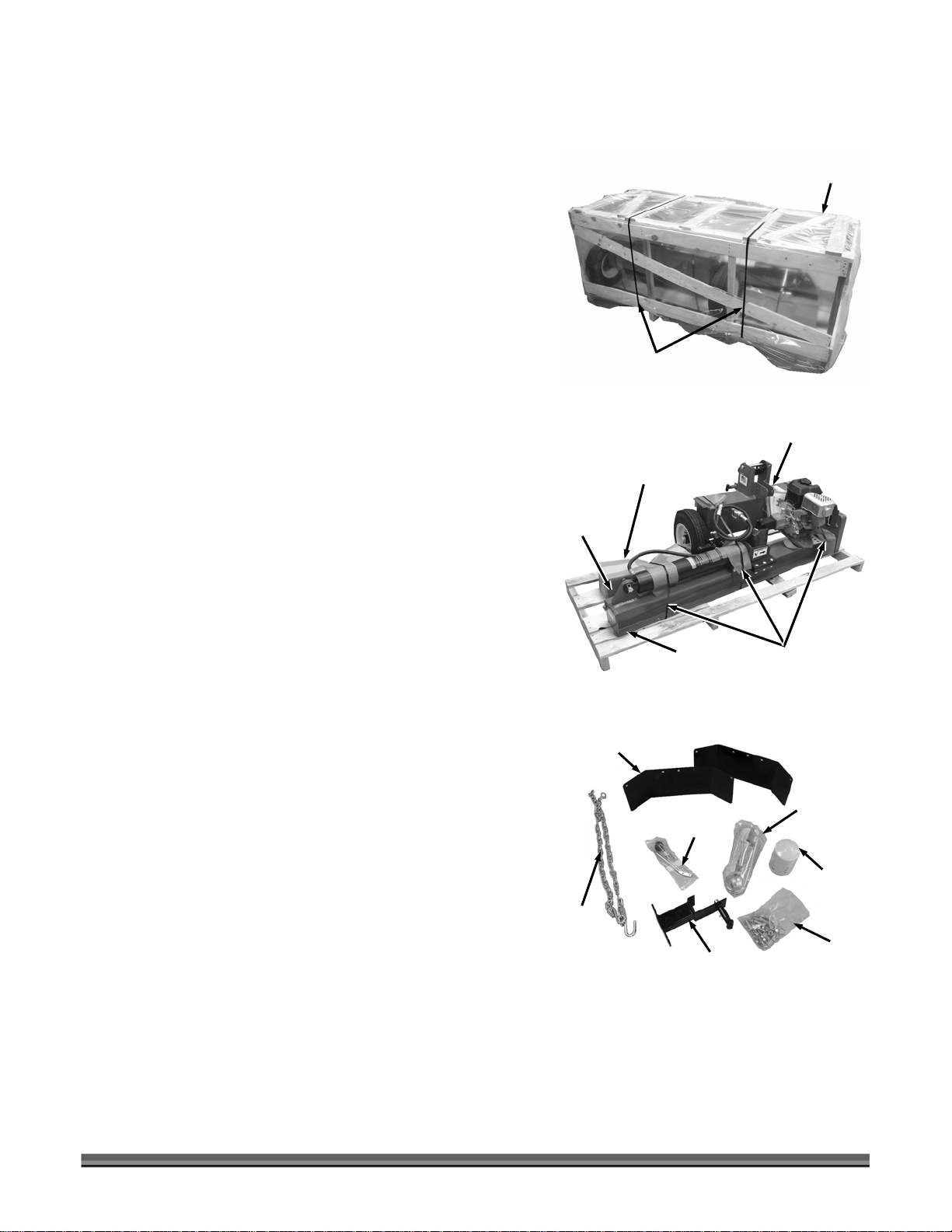
Unpacking the Crate
A
1. Cut the metal banding and remove the protective
plastic covering, top, sides and ends, of the packing
crate (Figure 2). Do not remove the base unit or the
rail assembly from the bottom pallet at this time.
2. Locate and check the condition of the larger
components on the shipping pallet (Figure 3). If you
have any questions, call DR Power Equipment at 1
(800) 376-9637.
3. Cut the remaining banding straps, open the cardboard
box, and make sure all the smaller parts have been
shipped. The chart in the “Shipping List” section
provides a complete list of all the parts shipped with
your wood splitter. If you have any questions, call DR
Power Equipment at 1 (800) 376-9637.
Metal Banding
Figure 2
Tongue and
Front Leg
Assembly
Figure 3
Cardboard
Box
Rail
ssembly
Packing
Crate
Base Unit
Banding
Straps
NOTE: The contents of the cardboard box (Figure 4) contains
the tow hitch assembly, two safety chains and safety
link, two fenders, valve handle assembly, hydraulic
fluid filter, and rail rest assembly.
Also, included in the box is a plastic bag of miscellaneous
hardware and a plastic bag with the control valve
handle assembly.
Fenders
Safety
Chains
Figure 4
Tow Hitch
Control Valve
Handle Assembly
Rail Rest and
Locking Lever
Assembly
Contact us at www.DRpower.com 13
Assembly
Hydraulic
Fluid Filter
Hardware
Page 14
Assembly Procedure
J
SOME COMPONENTS ARE VERY HEAVY AND CAN BE DAMAGED IF MISHANDLED. ALSO, TO HELP
PREVENT PERSONAL INJURY, IT IS RECOMMENDED THAT TWO (2) PEOPLE WORK TOGETHER TO
UNCRATE AND ASSEMBLE THE WOOD SPLITTER.
READ ALL INSTRUCTIONS AND SAFETY RECOMMENDATIONS BEFORE ASSEMBLING OR OPERATING
THIS WOOD SPLITTER.
Top of Tongue and
Base
Unit
Front Leg Assembly
Flush with top of
Base Unit Bracket
Tongue and
Front Leg
Assembly
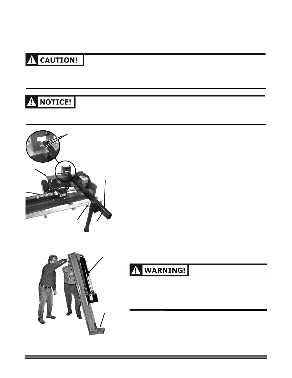
1. Before removing the base unit from the pallet, remove
the tongue and front leg assembly from the pallet and
fold the leg down and lock it into position with the
spring pin. Install the tongue and front leg assembly
onto the base using Two 1/2-13 x 3-1/2 inch long hex
head bolts and Locknuts (Figure 5). Tighten the
Locknuts securely. Pull the spring pin to fold the leg
back in the up position. Roll the tongue/base unit off
the pallet. Lower the front leg and lock it into position
with the spring pin.
Figure 5
Figure 6
Spring
Pin
Holes Closer
to Top of
Tongue
Rail Assembly
Base Plate
down
Note: Make sure that the mounting holes on the Tongue and Front
Leg Assembly are closer to the top when assembling so that the Top
of the Tongue and Front Leg Assembly is Flush with the Top of Base
Unit Bracket.
2. With a helper, carefully push the rail assembly off the
pallet and stand it in an upright, vertical position with
the base plate down (Figure 6).
MAKE SURE THE RAIL ASSEMBLY IS STANDING ON A FLAT,
LEVEL AREA. IF NECESSARY, HAVE A HELPER STEADY THE
RAIL TO PREVENT IT FROM TIPPING OVER. THE RAIL
ASSEMBLY WEIGHS APPROXIMATELY 300 POUNDS AND
WILL CAUSE BODILY IN
URY IF IT FALLS ON SOMEONE.
14 DR
®
22-TON VERTICAL/HORIZONTAL WOOD SPLITTER
Page 15

3. While supporting the hinge bracket (Figure 7), pull the
FROM
NG DU
NG
.
hairpin clip and remove the hinge pin to separate the
hinge bracket.
Hinge
Pin
4. Pull out and twist the locking lever to lock it in the out
position.
NOTE: For the next step, use the third set of mounting holes
up from the Base Plate.
5. Make sure the notch is on top as you position the
hinge bracket onto the rail assembly (Figure 8). Install
two 1/2-13 x 1-1/2 inch long hex head bolts, lock
Washers, and nuts. Only hand tighten the nuts at this
time.
HAVE SOMEONE HOLD THE RAIL ASSEMBLY TO PREVENT
IT
FALLI
RI
THIS PART OF THE ASSEMBLY
Hairpin
Clip
Figure 7
Rail
Assembly
Notch on
top
Bolts (far side),
Lock Washers
and Nuts
Figure 8
Locking
Lever
Hinge
Bracket
Hinge Bracket
(mount in the
third set of
holes up from
the Base Plate)
Base Plate
6. Position the base unit against the rail assembly
(Figure 9).
Rail
Assembly
Base Unit
Figure 9
Contact us at www.DRpower.com 15
Page 16

Hinge
Pin
Hairpin
Clip
Base
Unit
Figure 10
Rail
Assembly
7. Attach the base unit and the rail assembly together by
installing the hinge pin and hairpin clip (Figure 10).
Hinge
Bracket
Rail
Rest
Locking Lever
Figure 11
Bolts (far side),
Lockwashers and Nuts
Unlock
Rail
Assembly
8. Only hand tighten the nuts
as you bolt the rail rest to
the rail assembly using two 1/2-13 x 1-1/2 inch long
hex head bolts, lock Washers, and nuts (Figure 11).
9. Pull the locking lever outward and rotate the handle to
hold the lock pin in the unlocked position.
10. Block the wheels to prevent the base unit from
moving. Carefully lower the rail assembly to horizontal
position (Figure 12). Securely tighten the nuts holding
the base unit to the rail assembly (Step 5) and the nuts
holding the rail rest assembly (Step 8).
Figure 12
16 DR
®
22-TON VERTICAL/HORIZONTAL WOOD SPLITTER
Page 17

11. Link the ends of safety chains together with the safety
l
quick-link and tighten the link’s locknut securely with
a wrench (Figure 13).
Safety
Chains
Safety
Quick-Link
Figure 13
12. Place the hitch over the attachment tube, aligning the
bolt holes, and insert the rear 1/2-13 x 3 inch bolt (A).
Install and tighten the locknut (Figure 14).
13. Insert the large end of the safety chain quick-link into
the front tube of the rail assembly and insert a 1/2-13
x 3 inch bolt (B) through the hitch and link. Install and
tighten the locknut.
14. Install the valve link onto the valve body (Figure 15)
using a 1/4 x 1 inch long clevis pin (install clevis pin
from the top). Secure the clevis pin with a cotter pin
(bend the ends of the cotter pin to make it secure).
A
B
Figure 14
Clevis Pin
Hitch
Install Inside
of Hitch and
Rai
Safety
Chains
Valve
Body
Valve
Link
Figure 15
Contact us at www.DRpower.com 17
Cotter
Pin
Page 18

g
Figure 16
Clevis
Pin
15. Install the control valve handle onto the valve link
(Figure 16) using a 1/4 x 3/4 inch long clevis pin
(install clevis pin from the top). Secure the clevis pin
with a cotter pin (bend the ends of the cotter pin to
make it secure).
Cotter
Pin
Control
Valve Handle
Clevis
Pin
Figure 17
Valve
Fitting
Valve
Spool
Cotter
Pin
From Filter
Assembly
Control
Valve
Handle
Knob
16. Attach the control valve handle to the valve spool
(Figure 17) using a 1/4 x 1 inch long clevis pin (install
clevis pin from the top). Secure the clevis pin with a
cotter pin (bend the ends of the cotter pin to make it
secure). Attach the knob to the control valve handle,
if necessary.
17. Attach the high-pressure hose from the filter assembly
to the fitting on the side of the valve (Figure 18).
Securely tighten the hose fitting with a 10-inch
crescent wrench.
NOTE: The high-pressure hose is self-sealing and does not require
any type of sealing material.
Figure 18
18 DR
High
Pressure
Hose Fittin
®
22-TON VERTICAL/HORIZONTAL WOOD SPLITTER
Page 19

18. Wrap the threads of the high-pressure hose fitting with
a hydraulic pipe tape and attach it to the hydraulic
pump (Figure 19). Securely tighten the high-pressure
hose fitting with a 10-inch crescent wrench.
High-Pressure
Hose Fitting
From Bottom
Valve Fitting
Hydraulic
Pump
Figure 19
19. Remove the hydraulic fluid filter from the plastic cover
and apply a thin coat of hydraulic fluid to the rubber
seal. Screw the filter onto the filter head (Figure 20),
located near the hydraulic tank. Once the filter seal
makes contact with the filter head, turn it an additional
3/4 turn. Hand-tighten only.
20. Bolt the fenders onto the fender brackets using two
5/16-18 x 3/4 inch long hex head bolts and locknuts
(Figure 21). The fenders are interchangeable (left or
right). Position the fender over the tire with equal
spacing in the front and back.
NOTE: Your DR 22-Ton Vertical/Horizontal Wood Splitter is
now completely assembled. Follow the “Start-Up
Procedure” in the following section, which adds oil to
the engine and hydraulic fluid to the hydraulic tank
before trying to start the engine.
Filter
Head
Hydraulic
Fluid
Filter
Figure 20
Bolts (Top
side) and
Locknuts
Fender
Figure 21
Contact us at www.DRpower.com 19
Page 20

Start-Up Procedure
READ AND FOLLOW ALL OF THE INSTRUCTIONS IN THE “START-UP PROCEDURE” BEFORE STARTING
THE ENGINE AND OPERATING THE WOOD SPLITTER. FAILURE TO FOLLOW THIS RECOMMENDATION
WILL RESULT IN ENGINE AND HYDRAULIC PUMP DAMAGE.
ANY UNAUTHORIZED CHANGES OR MODIFICATIONS TO THE WOOD SPLITTER WILL VOID ALL
WARRANTIES.
THE HYDRAULIC FLUID FILTER FOR YOUR WOOD SPLITTER IS NOT FACTORY INSTALLED. MAKE SURE
THE FILTER IS INSTALLED BEFORE ATTEMPTING TO FILL THE HYDRAULIC TANK OR START THE
ENGINE. (INSTALLATION INSTRUCTIONS ARE PROVIDED IN THE “ASSEMBLY INSTRUCTIONS”
SECTION AND ARE ALSO PRINTED ON THE SIDE OF THE FILTER).
BEFORE STARTING THE ENGINE, READ THE ENGINE MANUFACTURER’S OPERATING AND
MAINTENANCE INSTRUCTION MANUAL. IF AN ENGINE MANUAL WAS NOT SUPPLIED WITH THE
WOOD SPLITTER, PLEASE CONTACT OUR CUSTOMER SERVICE REPRESENTATIVES AT OUR TOLL FREE
NUMBER: 1-800-DR-OWNER (376-9637).
1. Remove the hydraulic fluid fill cap and fill the hydraulic
tank (Figure 22) with the recommended fluid (see the
“specifications” section, page 2). The tank is full when
the fluid level is approximately one inch from the top
of the tank. Do not tighten the fill cap at this time.
Figure 22
Crank Case
Fill Cap
Figure 23
Hydraulic
Tank
NOTE: The total hydraulic system fluid capacity is 9.5 gallons.
Hydraulic
Fluid Fill
Cap
2. Remove the crank case fill cap (Figure 23) and fill the
engine’s crank case with the engine manufacturers
recommended oil in the engine operators manual.
NOTE: fill the crank case with oil all the way up to the threads of the
fill cap hole until it is about to overflow.
20 DR
®
22-TON VERTICAL/HORIZONTAL WOOD SPLITTER
Page 21

3. Lubricate the surface of slide rail with a general-
d
purpose grease (Figure 24). This will help to prevent
wear between the slide plates and the slide rail.
4. Pull the spark plug wire off the spark plug (Figure 25).
This prevents the engine from starting until the
hydraulic pump and cylinder are completely filled with
fluid. Make sure the spark plug wire is held away from
the spark plug with string or other nonconductive
material.
Lubricate
Slide Rail
Figure 24
5. Push the control valve handle to the forward position
(towards the front of the cylinder) (Figure 26). Have
another person pull the engine starter cord (about 15
times) until the cylinder piston moves forward. (Keep
everything away from the splitting wedge during this
step.)
NOTE: Extending the cylinder draws the hydraulic fluid
through the system and expels any trapped air in the
cylinder.
6. Check the fluid level in the hydraulic tank and add fluid
as needed. Replace and tighten the fill cap.
Figure 25
Engine
Starter
Cor
Figure 26
Spark
Plug Wire
Control
Valve
Handle
Contact us at www.DRpower.com 21
Page 22

BE CAREFUL NOT TO SPILL FUEL WHEN FILLING THE ENGINE. IF FUEL SHOULD SPILL, QUICKLY WIPE
HIG
.
J
r
OFF AND ALLOW THE EXCESS FUEL TO EVAPORATE BEFORE CONTINUING. FUEL AND FUEL VAPORS
ARE
HLY FLAMMABLE AND CAN CAUSE PERSONAL INJURY OR EVEN DEATH WHEN IGNITED
DO NOT MIX OIL WITH THE GASOLINE. USING MIXED OIL/GASOLINE IN A FOUR CYCLE ENGINE CAN
CAUSE ENGINE DAMAGE.
Spark
Plug Wire
Choke Control
Leve
Figure 27
Control
Valve
Handle
Throttle
Control
Lever
Recoil Starter
Handle
Gas Fill
Cap
7. Fill the engine’s fuel tank to within about 1-1/2" of the
neck with fresh, clean, lead-free automotive gasoline
(Figure 27).
8. Attach the spark plug wire and make sure the fuel
shut-off valve is in the “ON” position.
9. Move the choke control lever to the “CHOKE”
position.
10. Move the throttle control lever to the “fast” position.
11. Grasp the recoil starter handle
and slowly pull until
you feel resistance. Let the cord retract a little bit, then
pull the cord rapidly to start the engine. One or two
pulls usually starts the engine.
12. Move the choke control lever back to the “RUN”
position when the engine is running.
13. With the engine running, push the control valve
handle to the retract position and retract the cylinder
piston (Figure 28). The cylinder valve will automatically
stop the cylinder from retracting when it reaches the
end of its stroke. Cycle the wood splitter several times.
DO NOT REMOVE THE CAP FROM THE HYDRAULIC TANK
Figure 28
OR RESERVOIR WHILE THE WOOD SPLITTER IS RUNNING.
HOT OIL, UNDER PRESSURE, COULD BE EXPELLED
RESULTING IN SERIOUS IN
URY.
14. Move the throttle control lever
to the “SLOW” position and then to the “STOP” position to stop the engine.
15. Again, check the fluid level in the hydraulic tank and add fluid as needed. Replace and tighten the fill
cap.
16. Your DR 22-Ton Vertical/Horizontal Wood Splitter is now ready to use.
22 DR
®
22-TON VERTICAL/HORIZONTAL WOOD SPLITTER
Page 23

Chapter 3: Operating Your Wood Splitter
(
DO NOT ATTEMPT TO OPERATE THE WOOD SPLITTER
WITHOUT FULLY UNDERSTANDING ALL INSTRUCTIONS,
SAFETY PRECAUTIONS, AND/OR WARNINGS. IF ANY DOUBT
OR QUESTION ARISES ABOUT THE CORRECT OR SAFE
METHOD OF PERFORMING ANYTHING FOUND IN THIS
MANUAL, PLEASE CONTACT OUR CUSTOMER SERVICE
REPRESENTATIVES AT OUR TOLL FREE NUMBER: 1-800-DROWNER (376-9637).
TOP VIEW
(HORIZONTAL)
Operator
Zone
WHEN OPERATING THE WOOD SPLITTER, MAKE SURE YOU
ARE STANDING IN THE SAFE OPERATING AREA (OPERATOR
ZONE) AS SHOWN IN FIGURE 29. YOU MUST STAY IN THE
SAFE OPERATING AREA AT ALL TIMES WHEN THE SPLITTING
WEDGE IS IN MOTION (WHETHER EXTENDING OR
RETRACTING). NEVER PLACE ANY PART OF YOUR BODY
INTO A POSITION THAT CAUSES AN UNSAFE OPERATING
CONDITION.
1. Set your wood splitter on flat, dry ground. Make sure
you read all the recommendations from the “General
Safety Rules” in chapter 2 before using the WOOD
SPLITTER.
2. Make sure the fuel shut-off valve is in the “ON”
position (Figure 30).
3. Move the choke control lever to the “CHOKE” position
(should only be needed if the engine is cold).
4. Move the throttle control lever to the “fast” position.
5. Grasp the recoil starter handle
and slowly pull until
you feel resistance. Let the cord retract a little bit, then
pull the cord rapidly to start the engine. One or two
pulls usually starts the engine.
Operator
Zone
Figure 29
Spark
Plug Wire
Choke Control
Lever
Figure 30
TOP VIEW
VERTICAL)
Throttle Control
Lever
Fuel
Shut-off
Valve
Recoil Starter
Handle
6. Move the choke control lever (if used for cold engine)
back to the “RUN” position when the engine is
running well.
7. Make sure both ends of the log you are splitting are
cut as square as possible (Figure 31). This will prevent
the log from sliding out of position while under
pressure. All logs should be 24 inches or shorter in
length.
Figure 31
Contact us at www.DRpower.com 23
Page 24

Figure 32
J
NEVER ATTEMPT TO SPLIT WOOD ACROSS THE GRAIN
(FIGURE 32). THE WOOD SPLITTER WAS NOT DESIGNED
FOR CROSS-GRAIN SPLITTING. DOING SO WILL DAMAGE
THE WOOD SPLITTER AND MAY CAUSE PERSONAL IN
URY.
8. If the wood splitter has not been running (cold
engine), warm up the engine and hydraulic system by
running the engine at half throttle for 3 to 4 minutes,
then advance the engine throttle control to maximum
speed.
BEFORE LOADING AND OPERATING THE WOOD SPLITTER,
ALWAYS WEAR PROTECTIVE GEAR, INCLUDING SAFETY
GOGGLES, HEARING PROTECTION, TIGHT-FITTING GLOVES
WITHOUT DRAW STRINGS OR LOOSE CUFFS, AND STEELTOED SHOES.
USE THE FOLLOWING PHOTOS FOR THE CORRECT AND
INCORRECT METHODS OF SPLITTING LOGS. NEVER SPLIT A
LOG USING AN INCORRECT OR UNSAFE METHOD.
Base
Plate
Figure 33
Figure 34
24 DR
Operation – Horizontal Position
DO NOT PLACE YOUR HANDS ON THE ENDS OF THE LOG
WHEN LOADING THE WOOD SPLITTER (FIGURE 34). THIS IS
A VERY UNSAFE METHOD AND COULD RESULT IN INJURY
TO YOUR HANDS.
®
22-TON VERTICAL/HORIZONTAL WOOD SPLITTER
9. Place the log on the wood splitter (Figure 33). Grasp
the log on the sides near the middle of the block.
Center the log, side-to-side, on the rail of the wood
splitter, making sure that one end is against the base
plate.
Page 25

10. Only using your hand, pull the control valve handle
N
.
forward (towards the log) (Figure 35). If the log moves
before it is contacted by the splitting wedge, release
the control lever and then reposition the log. Operate
the WOOD SPLITTER only when standing in the safe
operating area, shown in Figure 29.
MAKE SURE YOU STAND CLEAR FROM THE ENGINE’S
EXHAUST. HOT EXHAUST IS INTENSE AND CAN CAUSE
SERIOUS INJURY.
IF YOU FIND YOU MUST HOLD THE LOG UNTIL THE
WEDGE TOUCHES IT AND HOLDS IT IN PLACE, BE VERY
CAREFUL NOT TO PUT YOUR HAND BETWEEN THE LOG
AND THE END PLATE OR THE LOG AND THE WEDGE. IF
YOU MUST, HOLD THE LOG ON TOP AND IN THE MIDDLE.
REMOVE YOUR HAND IMMEDIATELY WHEN THE SPLITTING
WEDGE ENGAGES THE LOG. NEVER USE YOUR HIP OR ANY
EXTENSION DEVICE TO OPERATE THE CONTROL VALVE
DLE
HA
Control Valve Handle
Figure 35
DO NOT OPERATE THE WOOD SPLITTER BY REACHING
ACROSS THE RAIL (FIGURE 36). THIS IS A VERY UNSAFE
METHOD THAT COULD CAUSE PERSONAL INJURY OR EVEN
DEATH.
DO NOT REACH OR STEP ACROSS THE RAIL WHILE THE
WOOD SPLITTER IS RUNNING. THIS IS A VERY UNSAFE
METHOD THAT COULD CAUSE PERSONAL INJURY OR EVEN
DEATH.
11. Hold the control valve handle, to extend the splitting
wedge until the log is split or the cylinder rod stops at
its maximum travel position (Figure 37). Stop the
WOOD SPLITTER (forward movement) at any point in
the splitting process if you feel an unsafe log splitting
condition is occurring. As the log is being split, DO
NOT reach forward and attempt to catch the split
wood — let it fall to the ground.
Figure 36
Control
Valve
Handle
Figure 37
Contact us at www.DRpower.com 25
Page 26

Control Valve
Handle
12. Once the wedge reaches its full forward travel, pull
back on the control valve handle to the full retract
position (Figure 38). The ram of the cylinder will
automatically retract into the cylinder. It is not
necessary to hold the control lever as the cylinder
retracts. Stop the wedge if the log sticks (see caution
below). When the cylinder is fully retracted, the control
valve will automatically shift to a neutral position.
13. DO NOT load another log or remove split pieces until
the wedge has completely stopped and the control
Figure 38
handle automatically returns to the neutral position.
DEPENDING ON THE TYPE OF WOOD BEING SPLIT, A LOG MAY NOT ALWAYS BREAK INTO TWO
PIECES AND FALL TO THE GROUND. IF A LOG STICKS TO THE WEDGE AND STARTS TO RETURN WITH
WEDGE ON THE RETURN STROKE, THE WOOD SPLITTER IS EQUIPED WITH A LOG DISLODGER THAT
WILL REMOVE THE LOG FROM THE WEDGE IF NEEDED. DO NOT STAND NEAR THE LOG AS IT
CONTACTS THE LOG DISLODGER IN CASE IT FALLS FROM THE SLIDE RAIL
Rail Rest
Figure 39
Locking
Lever
Locking
Lever
Hinge
Bracket
Operation – Vertical Position
BEFORE LOADING AND OPERATING THE WOOD SPLITTER,
ALWAYS WEAR PROTECTIVE GEAR, INCLUDING SAFETY
GOGGLES, HEARING PROTECTION, TIGHT-FITTING GLOVES
WITHOUT DRAW STRINGS OR LOOSE CUFFS, AND STEELTOED SHOES.
USE THE FOLLOWING PHOTOS FOR THE CORRECT AND
INCORRECT METHODS OF SPLITTING LOGS. NEVER SPLIT A
LOG USING AN INCORRECT OR UNSAFE METHOD.
1. To operate the wood splitter in a vertical position, pull
the spring-loaded locking lever of the rail rest and
twist the locking lever either direction to lock it in the
“unlocked” out position (Figure 39).
2. Pull the spring-loaded locking lever of the hinge
bracket and twist the locking lever either direction to
lock it in the “unlocked” out position (Figure 40).
Figure 40
26 DR
®
22-TON VERTICAL/HORIZONTAL WOOD SPLITTER
Page 27

3. Block the wheels and stand the rail assembly up into a
vertical position (Figure 41).
4. Turn the spring-loaded locking lever knob of the Hinge
Bracket until the pin slides into the slot. This allows
the plunger to snap into place, securing the rail
assembly in a vertical position.
5. Move the log under the splitting wedge keeping your
hands on the sides of the log near the middle of the
block. Center the log making sure that the sawed end
is sitting on the base plate (Figure 42).
Rail
Assembly
Figure 41
MAKE SURE YOU STAND CLEAR FROM THE ENGINE’S
EXHAUST. HOT EXHAUST IS INTENSE AND CAN CAUSE
SERIOUS INJURY.
DO NOT PLACE YOUR HANDS ON TOP OF THE LOG WHEN
LOADING THE WOOD SPLITTER. THIS IS A VERY UNSAFE
METHOD AND COULD RESULT IN INJURY TO YOUR
HANDS (FIGURE 43).
IF YOU FIND YOU MUST HOLD THE LOG UNTIL THE
WEDGE TOUCHES IT AND HOLDS IT IN PLACE, BE VERY
CAREFUL NOT TO PUT YOUR HAND ON TOP OF THE LOG.
IF YOU MUST, HOLD THE LOG IN THE MIDDLE OF THE
BLOCK. REMOVE YOUR HAND IMMEDIATELY WHEN THE
WEDGE ENGAGES THE LOG. NEVER USE YOUR HIP OR
ANY EXTENSION DEVICE TO OPERATE THE CONTROL
VALVE HANDLE.
Base
Plate
Figure 42
Figure 43
Contact us at www.DRpower.com 27
Page 28

Figure 44
Figure 45
Control
Valve
Handle
Control
Valve
Handle
6. Only using your hand, pull the control valve handle
down (towards the log) (Figure 44). If the log moves,
before it is contacted by the splitting wedge, release
the control valve handle and then reposition the log.
Operate the WOOD SPLITTER only when in the safe
operating area, as shown in Figure 29.
7. Hold the control valve handle to extend the splitting
wedge until the log is split or the cylinder rod stops at
its maximum travel position (Figure 45). Stop the
wood splitter downward movement at any point in the
splitting process if you feel an unsafe log splitting
condition is occurring. As the log is being split, DO
NOT reach forward and attempt to catch the split
wood — let it fall to the ground.
8. Once the wedge reaches its full downward travel, pull
up on the control valve handle to the full retract
position (Figure 46). The ram of the cylinder will
automatically retract into the cylinder. It is not
necessary to hold the control valve handle as the
cylinder retracts. Stop the wedge if the log sticks (see
caution below). When the cylinder is fully retracted,
the control valve will automatically shift to a neutral
position.
Figure 46
28 DR
Control
Valve
Handle
DEPENDING ON THE TYPE OF WOOD BEING SPLIT, A LOG
MAY NOT ALWAYS BREAK INTO TWO PIECES AND FALL TO
THE GROUND. IF A LOG STICKS TO THE WEDGE AND
STARTS TO RETURN WITH WEDGE ON THE RETURN
STROKE, THE WOOD SPLITTER IS EQUIPED WITH A LOG
DISLODGER THAT WILL REMOVE THE LOG FROM THE
WEDGE IF NEEDED. DO NOT STAND NEAR THE LOG AS IT
CONTACTS THE LOG DISLODGER IN CASE IT FALLS FROM
THE SLIDE RAIL.
®
22-TON VERTICAL/HORIZONTAL WOOD SPLITTER
9. DO NOT load another log or remove split pieces until
the wedge has completely stopped and the control
valve handle automatically returns to the neutral
position.
Page 29

To w ing
g
MAXIMUM SPEED LIMIT — 35 MPH
YOUR WOOD SPLITTER IS BUILT ON A SOLID, UNSUSPENDED AXLE. TO PREVENT DAMAGE OR
POSSIBLE LOSS OF VEHICLE CONTROL, USE EXTREME CAUTION WHEN TOWING AND DO NOT
EXCEED A VEHICLE SPEED OF 35 MPH, ESPECIALLY WHEN DRIVING ON A BUMPY ROAD. TIRE
PRESSURE SHOULD BE 40PSI.
1. Pull the latch assembly on the tow hitch assembly up
and into the open position. Position the hitch coupler
of the WOOD SPLITTER over and onto the tow
vehicle’s tow ball (must be a 2" tow ball) (Figure 47).
In some cases, the hitch coupler may not totally
engage with the tow ball without raising the front leg
weldment (see step 3).
2. Close the latch assembly on the tow hitch assembly to
lock the tow hitch assembly onto the tow ball (Figure
48). Attach the towing safety chains to the tow vehicle
ensuring there is enough slack for turning.
Tow
Hitch
Assembly
Figure 47
Latch
Assembly
Tow
Hitch
Assembly
Latch
Assembly
2" Tow Ball
Safety
Chains
Figure 48
3. Raise the front leg to the towing position by pulling
the spring pin (Figure 49). If not already secure, make
Spring Pin
sure the hitch coupler is properly and securely
attached to the tow ball.
Front Le
Figure 49
Contact us at www.DRpower.com 29
Page 30

Figure 50
Pull
1/16"
Movement
Latch
Assembly
Lock or
Lock Pin
Locking
Trigger
4. For extra safety and security, you may want to
purchase a lock or lock pin to install into the latch
assembly of the tow hitch assembly (Figure 50).
MAKING SURE THE WOOD SPLITTER IS SECURELY
ATTACHED TO THE VEHICLE IS THE RESPONSIBILITY OF
THE OWNER/OPERATOR. FAILURE TO SECURELY ATTACH
THE WOOD SPLITTER CAN CAUSE LOSS OF CONTROL OF
THE VEHICLE OR THE WOOD SPLITTER BEING SEPARATED
FROM THE TOWING VEHICLE, RESULTING IN SERIOUS
INJURY OR DEATH.
Hitch Coupler Adjustment Check
1. Place the proper size ball in the socket of the coupler
and close the latch assembly (Figure 51). Verify that
the locking trigger is properly engaged in its detent.
2. Pull on the ball and/or coupler, trying to remove the
ball from the socket. If the ball moves more than
1/16" in the coupler’s socket, the clamp requires
adjustment. Follow the proper adjustment
procedure in the following steps.
Figure 51
Lock Nut
Figure 52
Ball Clamp
Spring
Hitch Coupler Adjustment
1. With the proper size ball in the socket of the hitch
coupler, close the latch of the coupler completely
(Figure 52). Verify that the locking trigger is properly
engaged in its detent.
2. Tighten the lock nut on the underside of the coupler
until the spring between the nut and the clamp is fully
compressed. Then back off the lock nut 1/2 turn or
just enough that the latch is able to clamp and
unclamp from the ball.
30 DR
®
22-TON VERTICAL/HORIZONTAL WOOD SPLITTER
Page 31

Chapter 4: Inspection And Maintenance
This chapter covers regular maintenance procedures that will ensure the best performance and long life of
your machine. For engine maintenance, please refer to the engine owner’s manual that came with your
splitter. Service intervals listed in the check list below supercede those listed in the engine owner’s manual.
Regular Maintenance Check List
NOTE: Service intervals shown are considered maximum under normal operating conditions. Increase
frequencies under extremely dirty or dusty conditions.
Procedure
Check Engine Oil Level
Check General Equipment Condition
Check Wedge for Sharpness
Grease Surface of Slide Rail
Check Tire Pressure (40 psi)
Clean Engine Exterior and Cooling Fins
Change Engine Oil 1st time 5 hours
Replace Air Filter
Change Hydraulic Fluid Filter
Change Hydraulic Fluid
Replace Spark Plug
Before Each Use Every 25 Hours Every 100 Hours
▲
▲
▲
▲
▲
▲
▲
▲
▲
▲
▲
Contact us at www.DRpower.com 31
Page 32

General Maintenance Check (before operating)
J
The hydraulic system (hoses, cylinder, and pump) should be carefully inspected before each use. Also,
inspect the mechanical parts at the same time. Make sure all clamps, nuts, bolts, fittings, etc. are
properly installed and tightened.
DO NOT CHECK FOR LEAKS WITH YOUR HAND. LEAKS CAN BE LOCATED BY PASSING A PIECE OF
CARDBOARD OR WOOD AROUND THE SUSPECTED LEAK AND LOOKING FOR DISCOLORATION.
HIGH-PRESSURE FLUID ESCAPING FROM A VERY SMALL HOLE CAN BE ALMOST INVISIBLE. ESCAPING
FLUID UNDER PRESSURE CAN HAVE SUFFICIENT FORCE TO PENETRATE SKIN, CAUSING SERIOUS
INJURY OR EVEN DEATH. IF FLUID IS INJECTED INTO YOUR SKIN, IT MUST BE TREATED IMMEDIATELY
BY A DOCTOR FAMILIAR WITH THIS TYPE OF IN
Always replace frayed, kinked, or cracked hoses and/or other damaged hydraulic components with DR
Power Equipment authorized parts and components specified in the “Parts” section (Chapter 7) of this
manual. Replacement parts from secondary suppliers (not original DR Power Equipment replacement
parts) can lead to product damage and/or personal injury, and will void the warranty.
URY.
DO NOT REMOVE THE CAP FROM THE HYDRAULIC TANK OR RESERVOIR WHILE THE WOOD
SPLITTER IS RUNNING. HOT FLUID, UNDER PRESSURE, COULD BE EXPELLED RESULTING IN SERIOUS
INJURY.
Should it become necessary to loosen or remove any hydraulic fitting or line, be sure to relieve all
hydraulic pressure by shutting off the engine, removing the spark plug wire, and moving the valve
control handle back and forth several times until no cylinder movement is visible.
Engine Service
Refer to the engine manufacturers’ manual for engine maintenance, repair and storage.
Rail Maintenance
Between each use of the WOOD SPLITTER, we recommend applying a rust preventative (Fluid Film or
equivalent) to any bare metal areas on the top of the rail. This will assure the longest possible service life
of the wear pads.
32 DR
®
22-TON VERTICAL/HORIZONTAL WOOD SPLITTER
Page 33

Hydraulic Fluid Change
Tools needed:
• Screwdriver
• 10" crescent wrench
• Spark plug socket and Ratchet
1. Drain the head end of the cylinder.
a. Remove the spark plug wire and spark plug to help
reduce the back pressure on the engine and to prevent
it from starting.
NOTE: The total amount of hydraulic fluid in the system is
9.5 gallons.
b. Disconnect the return hose from the hydraulic fluid
filter housing and place it in a waste fluid container
(Figure 53). (Please properly dispose of the waste
hydraulic fluid per local regulations.)
c. Extend the cylinder by holding the hydraulic control
valve handle forward and have someone pull on the
engine’s pull start cord until fluid from the return line
stops flowing. This step drains the head end of the
cylinder.
Figure 53
Return
Hose
Inlet
Hose
Pump
2. Drain the hydraulic tank.
a. Place a waste fluid container under inlet hose (Figure
53).
b. Remove the inlet hose from the pump.
c. Slightly lower the front of the WOOD SPLITTER by
folding the leg assembly to completely drain the tank.
3. Remove and replace the hydraulic fluid filter.
a. Remove the existing hydraulic fluid filter and properly
dispose of it (Figure 54).
b. Apply a thin coat of hydraulic fluid to the rubber seal of
the new hydraulic fluid filter.
c. Screw the filter onto the filter head. Once the filter seal
makes contact with the filter head, turn it an additional
¾ turn. Hand-tighten only.
Filter
Head
Hydraulic
Fluid Filter
Figure 54
Contact us at www.DRpower.com 33
Page 34

Hydraulic
Tank
Fill Cap
4. Refill the hydraulic tank.
a. Reconnect inlet hose to the pump (Figure 53).
b. Remove the hydraulic tank fill cap and fill the tank with
the recommended type and quantity of hydraulic fluid
(Figure 55). Replace the cap.
5. Drain and refill the piston end of the cylinder.
a. Hold the valve handle in the retract position and pull
the engine pull start cord until the rod is fully
retracted. This step removes the old fluid from the
piston end of the cylinder.
Figure 55
b. Reconnect return hose to the hydraulic fluid filter
(Figure 53).
c. Extend the cylinder by holding the control valve handle
forward and pulling on the engine’s pull start cord
until the cylinder is completely extended. This step
refills the piston end of the cylinder.
6. Start the engine and cycle the cylinder.
a. Replace the spark plug and spark plug wire.
b. Start the engine and cycle the cylinder several times (see “Operating Your Wood Splitter”, Chapter
4).
c. Retract the cylinder and shut off the engine.
d. Recheck the hydraulic tank to make sure it is filled with fluid approximately one inch from the top of
the tank.
Hydraulic Fluid Specifications
Above 30˚ F . . . . . . . . . AW-32, 10W (non-foaming) or ATF DEXTRON III
Below 30˚ F . . . . . . . . . use only ATF DEXTRON III
Hydraulic Fluid Capacities
Hydraulic Tank . . . . . . . 7.5 Gallons
Hydraulic System (including cylinder, tank, hoses and filter) . . . . . . . 9.5 Gallons
34 DR
®
22-TON VERTICAL/HORIZONTAL WOOD SPLITTER
Page 35

End of Season and Storage
BEFORE PERFORMING ANY MAINTENANCE PROCEDURE, STOP THE ENGINE AND
DISCONNECT THE SPARK PLUG WIRE.
NOTE: Please refer to the engine owner's manual for engine-specific procedures.
• Change the engine oil.
• Remove the spark plug and pour about 1 ounce of motor oil into the cylinder hole. Replace the plug
and pull the recoil starter rope until you feel strong resistance. This will coat the piston and seat the
valves to prevent moisture buildup.
• Clean/replace the air filter.
• Clean dirt and debris from the cylinder head cooling fins and muffler area of the engine.
• If your DR 22-TON VERTICAL/HORIZONTAL WOOD SPLITTER will be idle for more than 30 days,
we recommend using a gas stabilizer. This will prevent sediment from gumming up the carburetor.
If there is dirt or moisture in the gas or tank, remove it by draining the tank. Completely fill the tank
with fresh, unleaded gas and add the appropriate amount of stabilizer or gasoline additive. Run the
engine for a short time to allow the additive to circulate. Close the fuel shut-off valve to prevent
carburetor overflow and leakage.
• Check the wedge for nicks and wear. Sharpen if needed.
• Apply Fluid Film to areas where the paint has worn or chipped off to bare metal.
Contact us at www.DRpower.com 35
Page 36

Chapter 5: Troubleshooting
Most problems are easy to fix. Consult the troubleshooting table for common problems and their
solutions. If you continue to experience problems call DR Power Equipment, Inc. Toll Free at 1-800-DR-
OWNER (376-9637) for support.
BEFORE PERFORMING ANY MAINTENANCE PROCEDURE, STOP THE ENGINE AND
DISCONNECT THE SPARK PLUG WIRE.
Troubleshooting Table
SYMPTOM POSSIBLE CAUSE
When the valve
control handle is
pushed forward
(extend), the splitting
wedge does not move.
⇒ Check the hydraulic tank to make sure the fluid level is one inch from the top of the tank.
⇒ If the fluid level is OK then call 1 (800) DR-OWNER (376-9637) for assistance.
The engine won’t
start.
(Please refer to the
engine owner’s
manual for enginespecific procedures.)
The engine lacks
power or is not
running smoothly.
(Please refer to the
engine owner’s
manual for enginespecific procedures.)
⇒ Check that the Fuel Shut-Off Valve is turned ON (See “Operating your WOOD
SPLITTER”, Chapter 4).
⇒ Are you using fresh, clean gas? If the gas is old, change it. Use a fuel stabilizer if
you keep gas longer than two months.
⇒ Is the spark plug clean? If the spark plug is dirty or cracked, change it. If it’s oily,
leave it out, hold a rag over the plug hole and pull the recoil cord several times to
blow out any oil in the cylinder, then wipe off the plug and reinsert it.
⇒ If your engine still won’t start, call 1(800) DR-OWNER (376-9637) for assistance.
⇒ Check that the Throttle Lever in the “Run” position.
⇒ Is the air filter clean? If it’s dirty, change it following the procedure in the engine
manufacturer’s owner’s manual.
⇒ Is the spark plug clean? If it’s fouled or cracked, change it. If it’s oily, leave it out,
hold a rag over the plug hole and pull your recoil cord several times to blow out
any oil in the cylinder, then wipe off the plug and reinsert it.
⇒ Are you using fresh, clean unleaded gas? If it’s old, change it. Use a fuel stabilizer
if you keep gas longer than two weeks or so.
⇒ Does your engine have the right amount of clean oil? If it’s dirty, change it
following the procedure in the engine manufacturer’s owner’s manual.
⇒ Check the oil level and adjust as needed.
⇒ If your engine still lacks power, call 1(800) DR-OWNER (376-9637) for assistance.
36 DR
®
22-TON VERTICAL/HORIZONTAL WOOD SPLITTER
Page 37

SYMPTOM POSSIBLE CAUSE
Engine smokes.
(Please refer to the
engine owner’s
manual for enginespecific procedures.)
The engine stalls
when the splitting
wedge engages the
wood.
⇒ Check the oil level and adjust as needed.
⇒ Check the air filter and clean or replace if needed.
⇒ You may be using the wrong oil—too light for the temperature. Refer to your
Engine Owner’s Manual for detailed information.
⇒ Clean the cooling fins if they’re dirty.
⇒ If the engine still smokes, call 1(800) DR-OWNER (376-9637) for assistance.
⇒ The engine may not be properly adjusted.
assistance
Call 1(800) DR-OWNER (376-9637) for
.
The splitting wedge
moves slowly, but will
split wood.
The ram will not
automatically retract.
Hydraulic fluid squirts
from the fill plug
during operation.
⇒ Check the hydraulic fluid level in the hydraulic tank and fill if necessary.
⇒ Check the high-pressure hose, fittings, and valve openings for dirt and debris that may
have obstructed the openings.
⇒ Check the slide rail or splitting wedge for damage.
⇒ Push the valve handle to the retract position. If the handle will not stay in this position,
call 1(800) DR-OWNER (376-9637) for assistance.
⇒ The hydraulic fluid tank may be over-filled. Drain fluid to 1 inch below the top of the tank.
⇒ The WOOD SPLITTER is not level. Make sure the WOOD SPLITTER is on level ground.
Contact us at www.DRpower.com 37
Page 38

Chapter 6: Parts Lists, Schematic Diagrams And Warranty
Parts List – Base Unit
NOTE: Part numbers listed are available through DR Power Equipment.
Ref# Part# Description
1 229741 Weldment, Base Tank
2 229751 Bolt, 5/16-18 x 3/4" long
3 229761 Fender
4 229771 Locknut, 5/16-18
5 229781 Seal, Inside
6 229791 Bearing, Tapered Roller
7 229801 Hub, Studded
8 229811 Tire, 4.8" x 8"
9 229821 Washer, Thrust
10 229831 Key, Cotter, 1/8"
11 229841 Dust Cap
12 229851 Nut, Spindle
13 229861 Nut, Lug
14 229871 Bolt, 5/16-18 x 1-3/4" long
15 229881 Washer, 5/16"
16 229891 Lock Washer, 5/16"
17 229901 Nut, 5/16-18
18 229911 Plug, Vented Fill
19 229921 O-ring, Vented Fill Plug
23 229961 Pin, Hinge
Ref# Part# Description
24 229971 Clip, Hairpin, 3/32 x 2-1/2" long
25 229981 Pin, Plunger
26 229991 Spring
27 230001 Pin, Slotted Spring, 3/16" dia.
28 230011 Knob, Bar
29 230021 Bracket, Hinge
30 229951 Nut, 1/2-13
31 229941 Lock Washer, 1/2"
32 229931 Bolt, 1/2-13 x 1-1/2" long
33 230031 Weldment, Tongue
34 230041 Weldment, Front Leg
35 230051 Coupler, Hitch, 2"
36 230061 Chain Assembly
37 230071 Bolt, 1/2-13 x 3-1/2" long
38 230081 Safety Quick-Link
39 230091 Locknut, 1/2-13
40 230101 Plug Cap
41 230111 Retaining Clip
42 230121 Jack Leg Plunger Kit
Safety & Information Labels (not shown)
38 DR
®
22-TON VERTICAL/HORIZONTAL WOOD SPLITTER
230611 Label, Warning, Towing Speed
230621 Label, Notice, Hydraulic Fill
Page 39

Schematic – Base Unit
Contact us at www.DRpower.com 39
Page 40

Parts List – Standard Rail
NOTE: Part numbers listed are available through DR Power Equipment.
Ref# Part# Description
1 230131 Weldment, Rail
2 229931 Bolt, 1/2-13 x 1-1/2" long
3 230141 Weldment, Rail Rest
4 229941 Lock Washer, 1/2"
5 229951 Nut, 1/2-13
6 229981 Pin, Plunger
7 229991 Spring
8 230001 Pin, Slotted Spring, 3/16" dia.
9 230011 Knob, Bar
10 230151 Retainer, Slide
11 230161 Guide, Slide
12 230171 Bolt, Carriage, 1/2-13 x 2-1/2"
13 230181 Weldment, Slide Wedge
14 230191 Pin, Clevis, 1/2 x 2-3/4" long
15 230201 Clip, Hairpin 3/32 x 1-3/4" long
16 230241 Cylinder
17 230211 Pin, Grooved, 1" dia.
18 230221 Clip, Hairpin (Cylinder)
19 230541 Log Dislodger
20 230581 Bracket, Clamp
21 230551 Bolt
22 230561 Washer
23 230571 Nut
Safety & Information Labels (not shown)
230591 Label, Warning, Pinch Point
265941 Label, Proper Machine Loading
230601 Label, Operating Instructions
40 DR
®
22-TON VERTICAL/HORIZONTAL WOOD SPLITTER
Page 41

Schematic – Standard Rail
Contact us at www.DRpower.com 41
Page 42

Parts List and Schematic – Pump and Piston Assembly
NOTE: Part numbers listed are available through DR Power Equipment.
Ref# Part# Description
1 230231 Engine, Briggs & Stratton
2 230251 Key, 3/16 x 1"
3 230261 Screw, Set, 1/4-20
4 230271 Coupling, Engine
5 230281 Spider
6 230291 Coupling, Pump
7 230301 Small Flange, Engine
8 229891 Lock Washer
9 230311 Bolt, 5/16-24 x 3/4" lg.
10 230351 Key
11 230361 Pump, Hydraulic
12 230521 Bolt, 5/16-24 x 5 1/2" long
13 230321 Casting, Head Filter
14 230331 Element, Filter
15 230341 Hose, High-Pressure
19
20
25
Ref# Part# Description
16 230371 Pin, Clevis, 1/4 x 1" long
17 230381 Valve Link
18 230391 Pin, Clevis, 1/4 x 3/4" long
19 230401 Knob
20 230411 Handle, Valve
21 230421 Pin, Cotter, 3/32 x 1/2" long
22 230431 Hose, High-Pressure
23 230441 Hose, Low-Pressure 1 x 9"
24 230451 Clamp, Hose, No. 16
25 230461 Fitting, High-Pressure, 90°
26 230471 Fitting, Straight
27 230481 Fitting, 90° Elbow
28 230491 Valve
29 230501 End Cap
30 230511 Hose, High-Pressure
26
27
16
18
42 DR
21
17
16
12
8
11
15
®
22-TON VERTICAL/HORIZONTAL WOOD SPLITTER
14
12
13
11
22
23
8
9
10
24
30
28
29
7
3
2
6
5
4
1
IO-C
Page 43

DR® 22-TON VERTICAL/HORIZONTAL
WOOD SPLITTER
2-Year Limited Warranty
®
Terms and Conditions
The DR
or workmanship when put to ordinary and normal consumer use; ninety (90) days for any other use. The engine
manufacturer warrants the engine separately.
For the purposes of all the above warranties, “ordinary and normal consumer use” refers to non-commercial residential
use and does not include misuse, accidents or damage due to inadequate maintenance.
Country Home Products, Inc. (home of DR
VERTICAL/HORIZONTAL WOOD SPLITTER is fit for ordinary purposes for which a product of this type is used.
Country Home Products, Inc. however, limits the implied warranties of merchantability and fitness in duration to a
period of two (2) year in consumer use, ninety (90) days for any other use.
The 2-Year Limited Warranty on the DR®22-TON VERTICAL/HORIZONTAL WOOD SPLITTER starts on the date the
machine ships from our factory. The 2-Year Limited Warranty is applicable only to the original owner.
The warranty holder is responsible for the performance of the required maintenance as defined by the manufacturer's
owner's manuals. The warranty holder is responsible for replacement of normally wearing parts such as the air filter,
spark plug, hydraulic fluid filter and tires. Attachments and accessories to the machine are not covered by this warranty.
During the warranty period, the warranty holder is responsible for the machine transportation charges, if required.
During the warranty period, warranty parts will be shipped by standard method at no charge to the warranty holder.
Expedited shipping of warranty parts is the responsibility of the warranty holder.
SOME STATES DO NOT ALLOW LIMITATIONS ON THE LENGTH OF IMPLIED WARRANTIES, SO THE ABOVE
LIMITATIONS MAY NOT APPLY TO YOU.
Country Home Products, Inc. shall not be liable under any circumstances for any incidental or consequential damages
or expenses of any kind, including, but not limited to, cost of equipment rentals, loss of profit, or cost of hiring services
to perform tasks normally performed by the DR
22-TON VERTICAL/HORIZONTAL WOOD SPLITTER is warranted for two (2) year against defects in materials
®
Power Equipment) certifies that the DR®22-TON
®
22-TON VERTICAL/HORIZONTAL WOOD SPLITTER.
SOME STATES DO NOT ALLOW THE EXCLUSION OR LIMITATION OF INCIDENTAL OR CONSEQUENTIAL
DAMAGES, SO THE ABOVE LIMITATIONS MAY NOT APPLY TO YOU.
THIS WARRANTY GIVES YOU SPECIFIC LEGAL RIGHTS, AND YOU ALSO HAVE OTHER RIGHTS, WHICH VARY
FROM STATE TO STATE.
Warranty
Page 44

Daily Checklist for the DR 22-TON VERTICAL/HORIZONTAL WOOD SPLITTER
To help maintain your DR 22-TON VERTICAL/HORIZONTAL WOOD SPLITTER for optimum
performance, we recommend you follow this checklist each time you use your machine.
[ ] OIL: With the machine on a level surface, check the engine oil level with the dipstick and add more if
necessary (only add oil to the level indicated on the dipstick - DO NOT OVERFILL). Use SAE 30
high detergent motor oil.
[ ] GAS: Fill the gas tank with clean, fresh, unleaded gasoline. Make sure the fuel shut-off valve on the front
of the engine is open. Always close the fuel shut-off valve when storing your machine.
[ ] ENGINE AIR COOLING SYSTEM: It is very important to keep the engine clean of debris. Remove wood
chips and other built-up materials from the air intake screen before, during and after you run the
splitter. Regularly remove debris from the cooling fins. A dirty engine retains heat and can cause
damage to the internal engine parts.
[ ] WEDGE: Check the wedge for tightness, nicks and wear.
[ ] GENERAL CONDITION: Check the general condition of the machine ( e.g.; nuts, bolts, welds etc.).
[ ] SLIDE RAIL: Apply a rust preventative (Fluid Film or equivalent) to any bare metal areas on the top of the
rail. This will assure the longest possible service life of the wear pads.
DR Power Equipment
MEIGS ROAD, P.O. BOX 25, VERGENNES, VERMONT 05491
1-800-DR-OWNER (376-9637) • www.dr-owner.com ©2009 CHP, Inc. 230531A
 Loading...