

Page 1
R
D
®
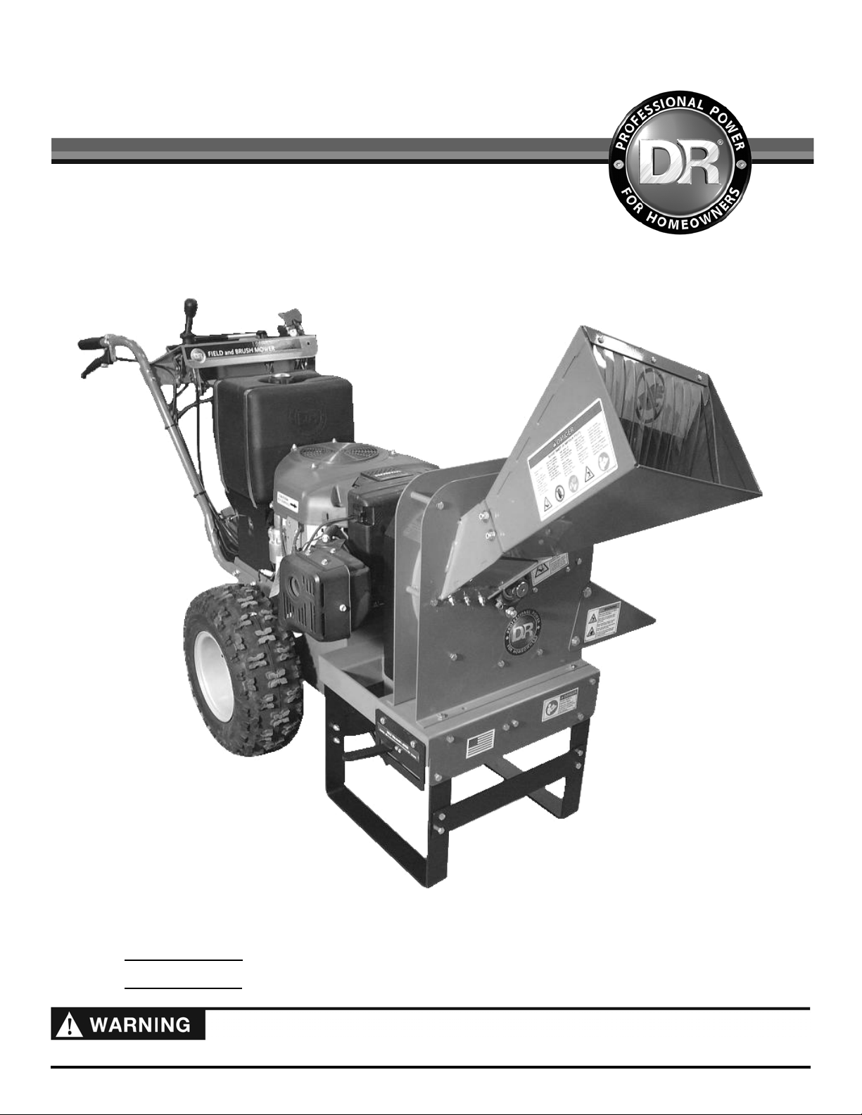
CHIPPER ATTACHMENT for the
DR® FIELD and BRUSH MOWER
SAFETY & OPERATING INSTRUCTIONS
DR Power Equipment
Serial No.
Order No.
Read and understand this manual and all instructions before operating the DR Chipper Attachment.
Toll-free phone: 1-800-DR-OWNER (376-9637)
Fax: 1-802-877-1213
Web site: www.DRpower.com
Page 2

Table of Contents
Chapter 1: General Safety Rules ......................................................................................................................... 3
Chapter 2: Setting Up Your DR CHIPPER ATTACHMENT ................................................................................ 6
Chapter 3: Operating Your DR CHIPPER ATTACHMENT ............................................................................... 14
Chapter 4: Maintaining The DR CHIPPER ATTACHMENT ............................................................................. 18
Chapter 5: Troubleshooting .............................................................................................................................. 26
Chapter 6: Parts Lists and Schematic Diagrams .............................................................................................. 28
Conventions used in this manual
This indicates a hazardous situation, which, if not followed, will result in death or serious injury.
This indicates a hazardous situation, which, if not avoided, could result in death or serious injury.
This indicates a hazardous situation, which, if not avoided, could result in minor or moderate injury.
This information is important in the proper use of your machine. Failure to follow this instruction could result in damage to
your machine or property.
Serial Number and Order Number
A Serial Number is used to identify your machine and is located on the Serial Number Label on your machine. An Order Number
is used to check and maintain your order history and is located on the upper left portion of your packing slip. For your
convenience and ready reference, enter the Serial Number and Order Number in the space provided on the front cover of this
manual.
Additional Information and Potential Changes
DR Power Equipment reserves the right to discontinue, change, and improve its products at any time without notice or obligation
to the purchaser. The descriptions and specifications contained in this manual were in effect at printing. Equipment described
within this manual may be optional. Some illustrations may not be applicable to your machine.
2 DR
®
CHIPPER ATTACHMENT
Page 3
#
#
#
#
#
#
#
Chapter 1: General Safety Rules
Read this Safety & Operating Instructions manual before you use the DR CHIPPER ATTACHMENT. Become familiar with the
operation and service recommendations to ensure the best performance from your machine.
Thoroughly inspect the area in which you will be working and remove all foreign objects. Look for rope, wire, etc., and remove
these objects before chipping. Inserting these objects into the chipper hopper could damage the machine and/or cause injury.
This is a high-powered machine, with moving parts operating with high energy at high speeds. You must use proper clothing
and safety gear when operating this machine to prevent or minimize the risk of severe injury. This machine can crush, grind,
cut, and sever parts of your body if they enter the inlet or discharge area of your chipper.
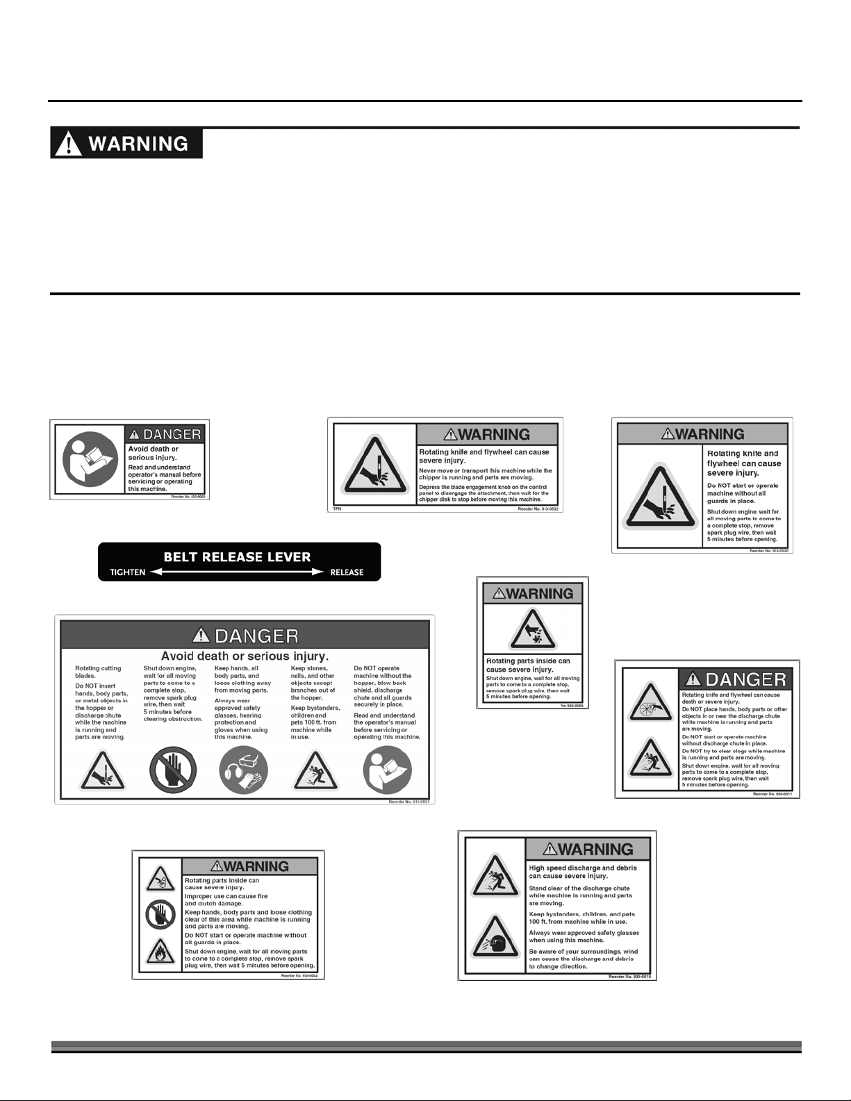
Labels
Your DR CHIPPER ATTACHMENT carries prominent labels as reminders for its proper and safe use. Shown below are copies of
all the safety and information labels that appear on the equipment. Take a moment to study them and make a note of their
location on your DR CHIPPER ATTACHMENT as you set up and before you operate the unit. Replace damaged or missing safety
and information labels immediately.
241801
247991
#247961
247981
#247971
241991
241811
241821
241831
CONTACT US AT www.DRpower.com 3
Page 4

Protecting Yourself and Those Around You
This is a high-powered machine, with moving parts operating with high energy at high speeds. You must operate the machine
safely. Unsafe operation can create a number of hazards for you, as well as anyone else in the nearby area. Always take the
following precautions when using this machine:
Always wear protective goggles or safety glasses with side shields while chipping to protect your eyes from possible thrown
debris.
Avoid wearing loose clothing or jewelry, which can catch on moving parts or the material fed into the chipper hopper.
We recommend wearing gloves while chipping. Be sure your gloves fit properly and do not have loose cuffs or drawstrings.
Wear shoes with non-slip treads when using your chipper. If you have safety shoes, we recommend wearing them. Do not
use the machine while barefoot or wearing open sandals.
Wear long pants while operating the chipper.
Use ear protectors or ear plugs rated for at least 20 dba to protect your hearing.
Never allow people who are unfamiliar with these instructions to use the chipper. Allow only responsible individuals who are
familiar with these rules of safe operation to use your machine.
Never place your hands, feet, or any part of your body in the chipper hopper, discharge opening, or near or under any moving
part while the machine is running. Keep area of discharge clear of people, animals, buildings, glass, or anything else that will
obstruct clear discharge, cause injury, or damage. Wind can also change discharge direction, so be aware. If it becomes
necessary to push material into the chipper hopper, use a small diameter stick, not your hands.
Keep bystanders 100 feet away from your work area at all times. Wood chips exit the chipper at great speeds. To be safe, do
not operate the machine near small children or pets, and never allow children to operate the chipper. Stop the chipper when
another person or pet approaches.
Disengage the blade at the control panel of the field and brush mower. Shut down the engine, wait for all moving parts to
come to a complete stop, remove spark plug wire keeping it away from the spark plug to prevent accidental starting, then wait
5 minutes before performing any maintenance or inspection on the chipper.
Never use the machine without ensuring that all guards and shields are in place, including the chipper hopper, discharge
chute and blowback shield.
Always operate the machine from the operator zone (see “operation notes” in chapter 4). Never pass or stand on the
discharge side of the machine when the engine is running or the flywheel is turning.
Never try to pick up, move, or transport the machine while the blade is engaged or the flywheel is turning. Disengage the
blade at the control panel of the field and brush mower. Shut down the engine, wait for all moving parts to come to a
complete stop, remove spark plug wire keeping it away from the spark plug to prevent accidental starting, then wait 5 minutes
before moving.
Never, under any conditions, remove, bend, cut, fit, weld, or otherwise alter standard parts on the DR CHIPPER
ATTACHMENT. This includes all shields and guards. Modifications to your machine could cause personal injuries and
property damage and will void your warranty.
Safety for Children and Pets
Tragic accidents can occur if the operator is not alert to the presence of children and pets. Children are often attracted to the
machine and the chipping activity.
precautions:
Keep children and pets at least 100 feet from the working area and ensure they are under the watchful care of a responsible
adult.
Be alert and turn the machine off if children or pets enter the work area.
Never allow children to operate the DR CHIPPER ATTACHMENT.
4 DR
®
CHIPPER ATTACHMENT
Never
assume that children will remain where you last saw them. Always follow these
Page 5

General Safety
Operating this chipper safely is necessary to prevent or minimize the risk of
number of hazards for you. Always take the following precautions when operating this chipper:
death or serious injury
. Unsafe operation can create a
Keep in mind that the operator or user is responsible for accidents or hazards occurring to other people, their property, and
themselves.
Your DR CHIPPER ATTACHMENT is a powerful tool, not a plaything. Exercise extreme caution at all times. The design of this
machine is to chip wood. Do not use it for any other purpose.
Know how to stop the chipper quickly; see “stopping the chipper” in chapter 4.
Operate this machine on a level surface only. Never operate your unit on a slippery, wet, muddy, or icy surface. Exercise
caution to avoid slipping or falling.
Keep your face and body back from the chipper hopper to avoid accidental bounce back of any material.
When feeding material into the chipper hopper, be extremely careful that pieces of metal, rocks, or other foreign objects are
not included. Personal injury or damage to the machine could result.
Never allow an accumulation of processed material to build up in the discharge area as this will prevent proper discharge and
can result in kickback from the chipper hopper.
Whenever you leave the operating position or if you have to remove processed material, leaves, or debris from the machine,
always disengage the blade at the control panel of the field and brush mower. Shut down the engine, wait for all moving parts
to come to a complete stop, remove spark plug wire keeping it away from the spark plug to prevent accidental starting, then
wait 5 minutes before removing processed material, leaves, or debris from the machine.
Always disengage the blade when moving the chipper attachment with the field and brush mower.
Keep combustible substances away from the engine when it is hot.
Never cover the machine while the muffler is still hot.
If the cutting mechanism strikes a foreign object or if your machine should start making an unusual noise or vibration,
disengage the blade at the control panel of the field and brush mower. Shut down the engine, wait for all moving parts to
come to a complete stop, remove spark plug wire keeping it away from the spark plug to prevent accidental starting, then wait
5 minutes before inspecting for clogging or damage. Vibration is generally a warning of trouble. Clean and repair and/or
replace damaged parts.
Never tamper with safety devices. Check their proper operation regularly.
Stay alert for hidden hazards or traffic. Never carry passengers on your machine.
Never overload or attempt to chip material beyond the manufacturer’s recommendation; see “using the chipper hopper” in
chapter 4. Personal injury or damage to the machine could result.
While using the DR CHIPPER ATTACHMENT, don't hurry or take things for granted. When in doubt about the equipment or
your surroundings, stop the machine and take the time to look things over.
Never operate the machine when under the influence of alcohol, drugs, or medication.
Use the machine only in daylight.
Keep all nuts and bolts tight and keep the equipment in good operating condition.
Additional Information and Potential Changes
DR Power Equipment reserves the right to discontinue, change, and improve its products at any time without notice or obligation
to the purchaser. The descriptions and specifications contained in this manual were in effect at printing. Equipment described
within this manual may be optional. Some illustrations may not be applicable to your machine.
No list of warnings and cautions can be all-inclusive. If situations occur that are not covered by this manual, the operator must
apply common sense and operate this chipper in a safe manner. Contact us at www.DRpower.com or call 1 (800) dr-owner (376-
9637) for assistance.
CONTACT US AT www.DRpower.com 5
Page 6
A
A
Chapter 2: Setting Up Your DR CHIPPER ATTACHMENT
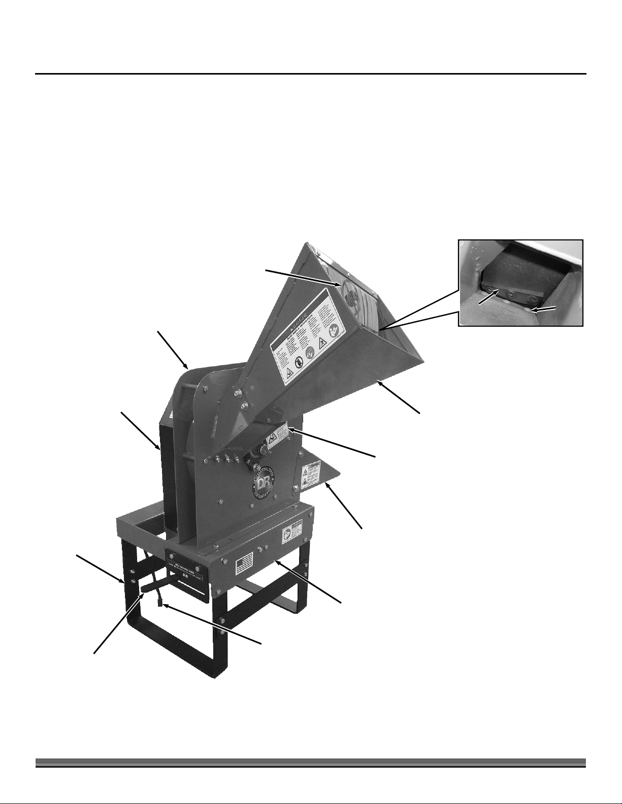
This chapter outlines unpacking and a few simple steps you will need to follow to set up your new machine before you use it. It
may be helpful to familiarize yourself with the controls and features of your DR CHIPPER ATTACHMENT as shown in Figure 1
before beginning these procedures.
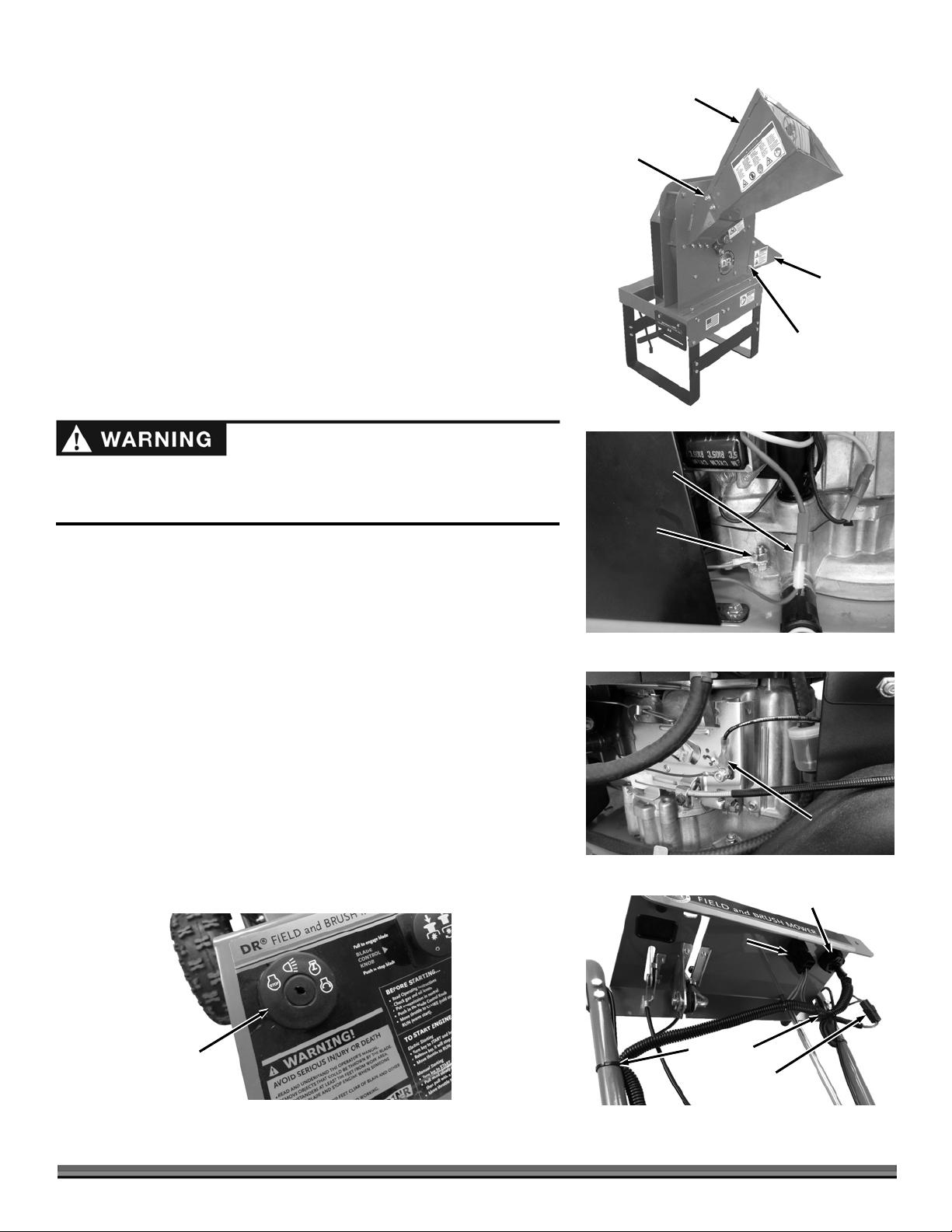
DR CHIPPER ATTACHMENT Controls and Features
Blow-back
Shield
Flywheel
Support
Legs
Belt Guard
Chipper
Basic
ssembly
Chipper Knife
ccess Cover
(Both Sides)
Discharge
Chute
Hopper
Chipper
Knife
Wear
Plate
Base
Field and
Belt Tighten/Release
Lever
6 DR
®
CHIPPER ATTACHMENT
Brush Mower
Connector
Figure 1
Page 7
Specifications
MECHANICAL SPECIFICATIONS
Shipping
Box
Tape
Straps
Driven by
DR Field and Brush Mower (V-Belt and
Clutch)
Chipping Capacity
Number of Chipper Knives
Chipper Knife Size
Chipper Knife Material
Adjustable Knife Wear Plate
Chipper Flywheel
Flywheel Weight
Chipper Knife Speed
Hopper Material
Belt Adjustment
3-1/2" Diameter
1
4-1/8" L x 1-1/4" W, 45 deg
Heat Treated Tool Steel
Yes
12" Diameter, 1/2" Thick
18 lbs
95 mph
14 GA Steel
Spring Loaded Idler Pulley W/Manual
Engagement
Hopper Opening at Top
Machine Weight
8" x 11"
125 lbs
SHIPPING SPECIFICATIONS
Shipping Dimensions
Shipping Weight
24" L x 26" W x 24" H
160 lbs
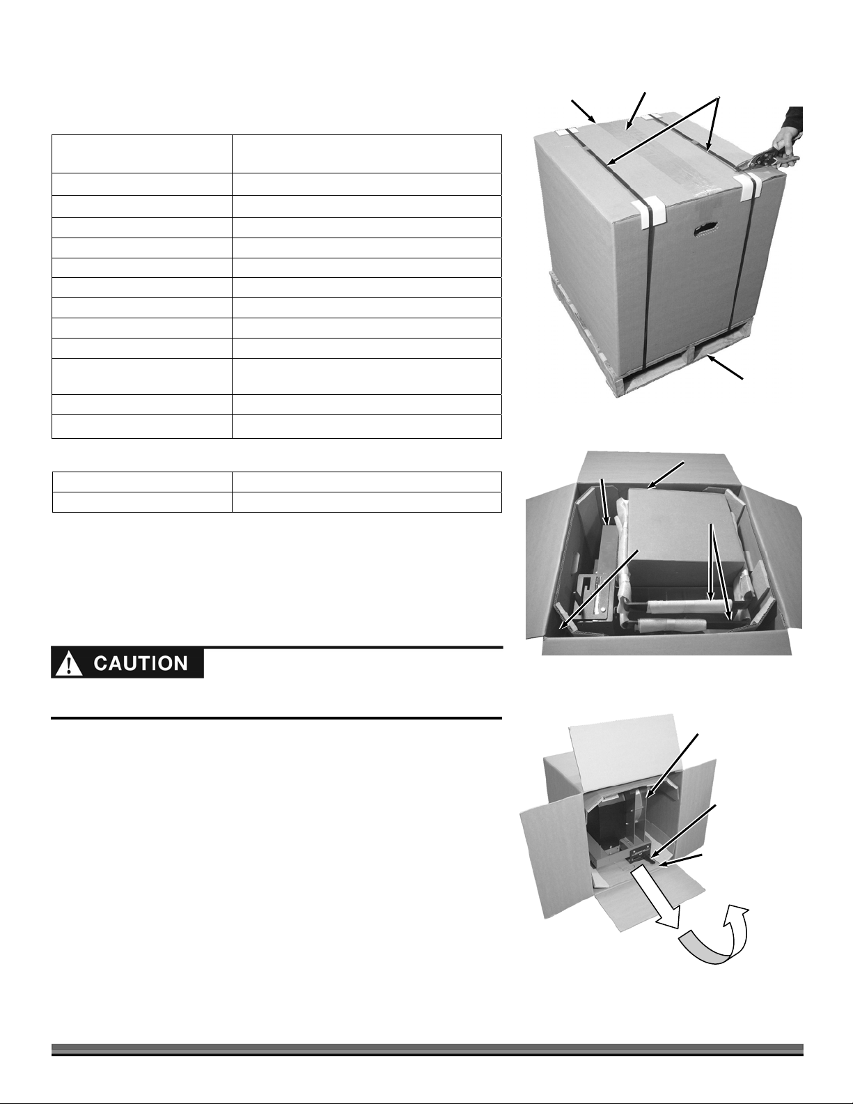
Unpacking The Chipper Attachment
Tools and Supplies Needed:
Figure 2
Chipper
Unit
Pallet
Parts
Box
Legs
Leg
Supports
Wire Cutters
Utility Knife
Safety Goggles
Wear eye protection when cutting the banding. The Banding may be under
tension causing it to snap towards you when it is cut.
1. Cut the Banding from around the Shipping Box and Pallet (Figure 2).
2. Cut the tape that secures the Box Flaps with a Utility Knife.
3. Open the Box Flaps and remove the Parts Box, Legs and Leg Supports
(standing up in the corner of the Box) (Figure 3).
4. Remove all Foam and Bubble Wrap from the Legs and Supports.
5. Slide the Box off the Pallet and rotate it onto the side so the Chipper Unit
is right side up (Figure 4).
6. Pull the Chipper Unit (with the Corner Supports) out of the Box and then
tip the Chipper Body up so the Belt Release Lever is on top.
Figure 3
Chipper
Unit
Belt Release
Lever
Corner Support
(Frame Side)
Figure 4
CONTACT US AT www.DRpower.com 7
Page 8

8 9
Belt
Figure 5
Hopper
Product Package (Owners Manual,
Hardware Bag, and Wire Harness)
3
Discharge
Chute
7. Cut open the Parts Box with a Utility Knife and remove the contents (Figure
5).
8. Remove the Bubble Wrap from the Discharge Chute.
9. Open the Product Package and remove contents.
10. Open the Hardware Package and remove contents.
Compare the contents of the Shipping Box, Parts Box and the Hardware
Package with the Parts Supplied list below. If there are any questions contact us
at www.DRpower.com or call 1-800-DR-OWNER (376-9637). Do not discard the
shipping materials until you are fully satisfied with your new DR CHIPPER
ATTACHMENT.
Parts Supplied:
Chipper Unit
Two Legs
Two Leg Supports
Parts Box Containing: (items in list below and Figure 5)
o Hopper
o Discharge Chute
o Belt
o Product Package Containing: Owners Manual, Wire Harness and
Hardware Package Containing: (items in table below and Figure 6)
1
5
6
Figure 6
Leg
Hardware
Harness
Connector
H
ARDWARE PACKAGE CONTENTS (FIGURE 7)
7
2
ITEM # DESCRIPTION QTY
1 Bolt, 5/16-18 X 4" 2
2 Carriage Bolt, 5/16-18 x 3/4" 4
4
3 Flat Washer, 5/16 8
4 Locknut, 5/16-18 24
5 Screw, 10-24 x 5/8" 1
6 Nut, Nylon Lock, 10-24 1
7 Bolt, 5/16-18 X 3/4" 18
8 Gap Gauge 1
9 Cable Tie 7
Assembling the Chipper Attachment
Leg Support
Hardware
Tools Needed:
Two 1/2" Wrenches
Soft Faced Hammer
1. Position the Legs onto the Chipper Body and install the Bolts and Locknuts
snug but not tight (Figure 7).
2. Position the Leg Supports onto the Legs and install Bolts and Locknuts snug
but not tight.
3. Pull the Harness Connector down from where it is tucked into the front of
Leg
Supports
Legs
Figure 7
8 DR
®
CHIPPER ATTACHMENT
the Frame so it will hang from the Cable Tie.
4. Tip the machine up onto the Legs, straighten the Legs as needed, then fully
tighten the Leg and Leg Support Hardware.
Page 9
Note: You may need to use a soft faced hammer to carefully tap the Bolts through
the holes in the next step.
5. Position the Discharge Chute on the side of the chipper and secure with two
Bolts, four Washers (one on each side), and two Locknuts using two 1/2"
wrenches (Figure 8).
NOTE: Ensure that the square in the Carriage Bolts slide fully into the slots in the
Hopper to ensure the bolt heads will rest flush to the Hopper surface.
Hopper
Carriage
Bolt, Washer
and Locknut
6. Position the Hopper and secure with four Carriage Bolts (Carriage Bolt Head
inside of Hopper and square of Bolt fully into slots in Hopper), four Washers
Discharge
Chute
and four Locknuts using a 1/2" wrench.
Replacing the Main Field and Brush Mower Harness on machines
Bolt, Washers
and Locknut
with a Briggs and Stratton 12.5 hp Engine (serial numbers from
Figure 8
Before performing this Harness change, stop the engine, wait five (5) minutes
to allow all parts to cool. Disconnect the spark plug wires, keeping them away
from the spark plugs.
ATM123741 to ATM126369).
Tools Needed:
1/2" Wrench
9mm Wrench
Wire Cutters
1. Disconnect the Charging Connector from the Engine (Figure 9).
2. Remove the Green Ground Wire from the Engine Mounting Bolt using a
1/2" Wrench.
3. Remove the Engine Kill Wire from the Throttle Linkage using a 9mm Wrench
(Figure 10).
4. Unplug the Blade Control, Key Switch and Operator Presence Connectors
(Figure 11).
5. Cut all Cable Ties that secure the Harness to the machine.
6. Remove the existing Key Switch by pushing in the Tabs underneath and
pulling it from the
Control Panel
(Figure 12).
7. Install the new Key
Switch into the
Control Panel.
Charging
Connector
Ground
Connector
Figure 9
Engine Kill
Connector
Figure 10
Key Switch Connector
Blade
Control
Connector
Key
Switch
Figure 12
Figure 11
CONTACT US AT www.DRpower.com 9
Cable Ties
Operator Presence
Connector
Page 10
A
8. Plug in the Blade Control, Key Switch and Operator Presence Connectors of the new Harness (Figure 11).
9. Route the Harness down the Handlebar to the Engine.
10. Install the Engine Kill Wire to the Throttle Linkage using a 9mm Wrench (Figure 10).
11. Install the Green Ground Wire to the Engine Mounting Bolt using a 1/2" Wrench (Figure 9).
12. Plug in the Charging Connector to the Engine.
13. Continue with “Installing the Chipper Wire Harness onto the DR Field and Brush Mower” on the next page.
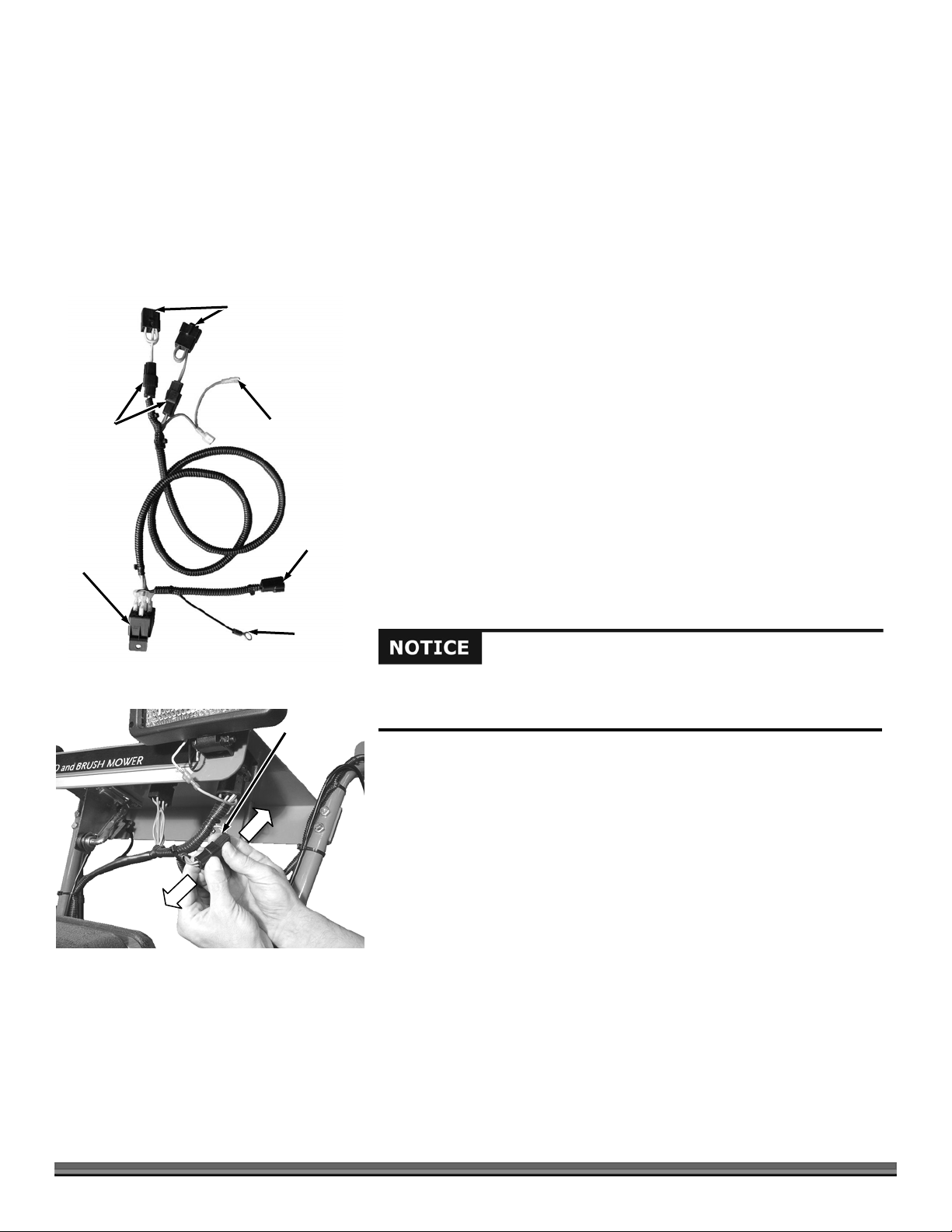
Installing the Chipper Wire Harness onto the DR Field and Brush Mower
Operator
Presence
Connectors
(for newer
models)
Relay
Figure 13
Blade Engagement
dapters (for older
models)
Light
Connector
Chipper
Connector
Ground
Wire
Operator
Presence
Connector
Tools Needed:
3/8" Open End Wrench
Phillips Screw Driver
Electric Drill (older Field and Brush Mowers)
3/16" Drill Bit (older Field and Brush Mowers)
Tape Measure (older Field and Brush Mowers)
1. Examine the Chipper Wire Harness and identify the connections (Figure 13).
2. Look at the Connectors under the Control Panel of the Field and Brush
Mower to identify the type of Connectors (machine) you have.
Note: If you have the older style machine (Figure 15 on next page), the Blade
Engagement Adapters (Figure 13) must stay on the Chipper Harness. If you have a
newer machine with the Operator Presence Connector (Figure 14) then the Blade
Engagement Adapters of the Chipper Harness are not needed.
Newer Field and Brush Mower
If you have an older field and brush mower that is manual-start, there is no
light connector in the wire harness. The DR Chipper Attachment cannot be
used with these machines.
1. Disconnect the Operator Presence Connector on the Field and brush Mower
(Figure 14).
2. Remove and discard the two Blade Engagement Adapters from the Chipper
Harness (Figure 13).
Newer Style Field and Brush Mower
Figure 14
10 DR
®
CHIPPER ATTACHMENT
Page 11

g
ght
3. Connect the two Connectors of the Chipper Harness to the Operator
Presence Connectors (Figure 15).
4. Connect the orange wire of the Chipper Harness to the orange wire coming
from the Mower Switch. If you have a light, connect the other orange wire of
the Chipper Harness to your light.
NOTE: All of the connectors will only fit one way.
Existing Operator
Presence Connectors
Orange
Wire to
Li
Older Field and Brush Mower
1. Disconnect the Operator Presence Connector on the Field and brush Mower
(Figure 16).
2. Connect the two Operator Presence Connectors of the Chipper Harness to
the Operator Presence Connectors of the Field and Brush Mower (Figure
17).
3. Connect the orange wire of the Chipper Harness to the orange wire coming
from the Mower Switch. If you have a light, connect the other orange wire of
the Chipper Harness to your light.
NOTE: All of the connectors will only fit one way.
Installing the Relay
1. If there is not a hole already there, Locate and drill a 3/16" hole in the Right
Side Gas Tank Support (Figure 18). Newer Field and Brush Mowers already
have a Relay mounting hole.
2. Route the Relay end of the Harness behind the Gas Tank Support and secure
the Relay to the hole with a 10-24 Screw and Locknut.
3. Connect the black Ground Wire to the Engine Mounting Hardware that is
closest to the Relay area.
4. Refer to Figure 19 for the proper relay color code connections in the event
your relay should become disconnected.
5. Wire Tie the Harness to the Handlebars of the Field and Brush Mower.
Orange
Wire from
Switch
Chipper Harness
Connectors
Figure 15
Operator
Presence
Connector
Older Style
Field and
Brush Mower
Figure 16
Chipper Harness
Connector Adapters
Switch
Figure 19
Gas
Tank
Support
Fi
ure 18
Ground
Wire
Engine
Mount
Hardware
Mounting
Screw and
Locknut
Relay
Existing
Operator
Light Switch
Connectors
Figure 17
3/16" Hole
Relay Mounted
Vertical
Right Side Gas
Tank Support
CONTACT US AT www.DRpower.com 11
Presence
Connectors
1"
1"
Page 12
g
Hand
Knob
Belt
Guard
Figure 20
Mounting
Hole in
Chipper
Frame
Carriage
Bolt
Guides
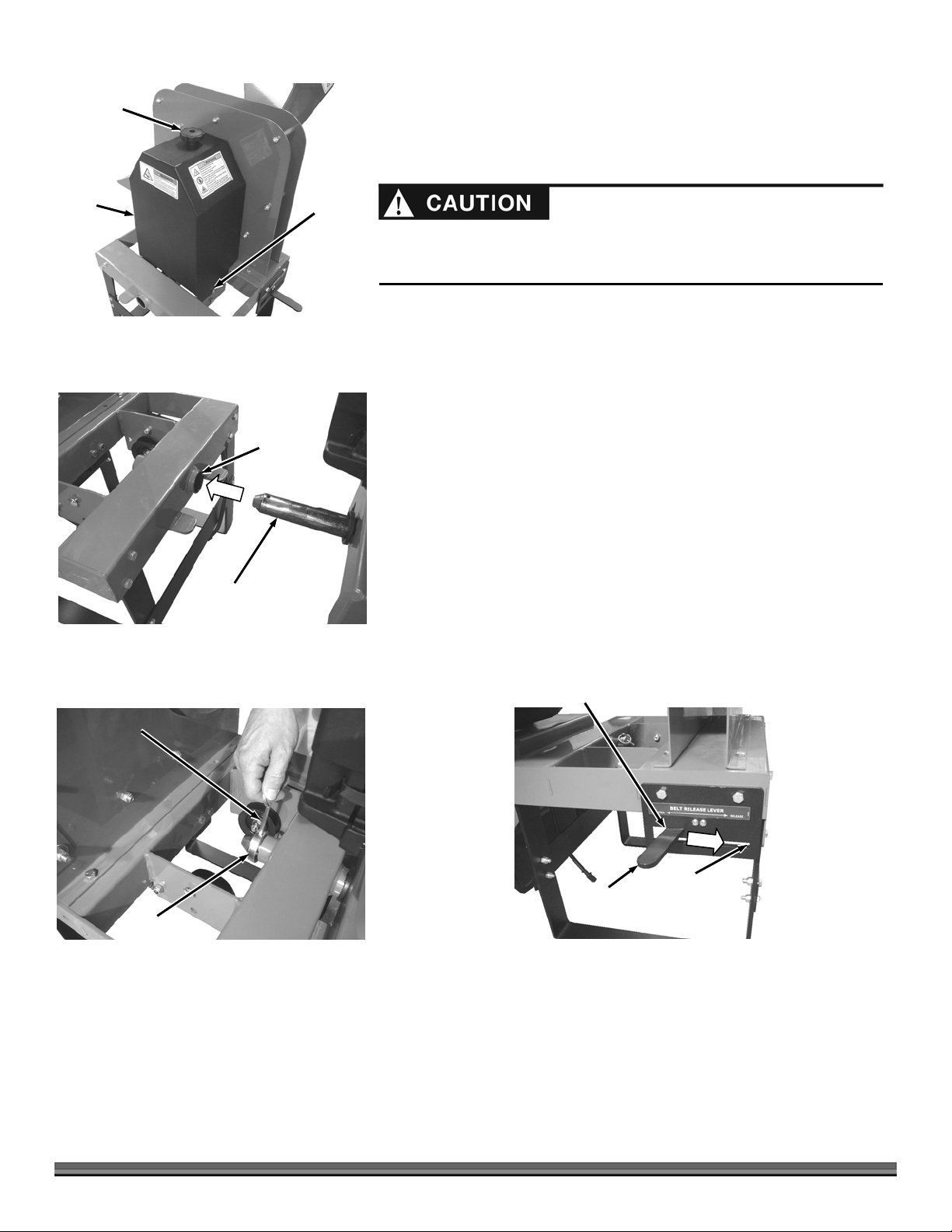
Mounting the Chipper Attachment to the Field and Brush Mower
1. Remove the Deck or other attachment from the Field and Brush Mower (see
your Field and Brush Mower Safety and Operating Instructions Manual).
Do not pull the Chipper or Brush Mower Attachment away from the Field and
Brush Mower unless you have someone holding the handlebars to prevent it
from fallin
2. Remove the Hand Knob from the top of the Belt Guard and remove the
Guard (Figure 20).
3. Make sure the Retaining Pin and Collar are removed from the Mounting
Shaft of the Field and Brush Mower.
4. With the help of another person to steady the Chipper as you position the
Field and Brush Mower; line up the FIELD AND BRUSH MOWER Mounting
Pin with the Mounting Hole in the Chipper Frame. Push the Field and Brush
Mower until the Pin is all the way into the Mounting Hole (Figure 21).
5. Reinstall the Pin and Collar onto the Mounting Shaft (Figure 22).
6. Make sure the Belt Release Lever is in the “Release” position (Figure 23).
backward.
Figure 21
Retaining
Pin
Figure 22
Collar
Field and Brush Mower
Mounting Shaft
Tighten Belt Position,
Left and Up
Belt Release
Lever
Figure 23
Release Belt
Position,
Down and
Right
12 DR
®
CHIPPER ATTACHMENT
Page 13

y
ys
f
t
Figure 24
Chipper Idler
Pulleys
Field and
Brush Mower
Pulle
Belt
Twist Belt to
Engage “V”
Properly into
Idler Pulle
Chipper
Sprocke
7. Position the Belt onto the Field and Brush Mower Pulley (Figure 24) and
then route it over the two Idler Pulleys and up around the Chipper Pulley
(Figure 25).
NOTE: Ensure that the “V” portion of the Belt rests properly into the Idler Pulleys.
8. Move the Belt Release Lever to the “Tighten” position.
NOTE: There is a slot in each of the bottom Tabs of the Belt Guard. These slots
must slide over the Carriage Bolt Guides that are mounted to the inner Frame
Supports of the Chipper (Figure 20 on previous page).
9. Reinstall the Belt Guard and secure with the Hand Knob.
10. Connect the Wire Harness Connector from the Field and Brush Mower to
the Connector of the Chipper Attachment (Figure 26).
Adjusting the Exhaust Deflector on machines with a Briggs and
Belt
Stratton 12.5 hp Engine (serial numbers from ATM123741 to
ATM126369).
Carriage
Bolt for
belt guard
mounting
(one on
each side)
Figure 25
Figure 26
Idler Pulleys
Connector
rom
Relay
Twist Belt so “V”
Engages Properly into
Chipper Sprocket
Chipper
Connector
Screws
Tool Needed:
Before performing this Engine change, stop the engine, wait five (5) minutes
to allow all parts to cool. Disconnect the spark plug wires, keeping them away
from the spark plugs.
1/4" Wrench
1. Remove the three Screws that secure the Exhaust Deflector using a 1/4"
Wrench (Figure 27).
2. Rotate the Exhaust deflector so it is facing forward (3 o’clock) and secure in
this position with the three Screws using a 10mm Wrench.
Point
Forward
Deflector
Figure 27
CONTACT US AT www.DRpower.com 13
Page 14
Chapter 3: Operating Your DR CHIPPER ATTACHMENT
This machine was designed for chipping wood. Never use this machine for any other purpose as it could cause serious injury.
Contact with internal rotating parts will cause serious personal injury. Never put hands, face, feet, or clothing into chipper
hopper or discharge opening or near the discharge area at any time.
Before performing any maintenance procedure or inspection, disengage the blade at the control panel of the Field and Brush
Mower. Shut down the engine, wait for all moving parts to come to a complete stop, remove spark plug wire keeping it away
from the spark plug to prevent accidental starting, then wait 5 minutes before proceeding. Use only a wooden stick to clear
jammed material.
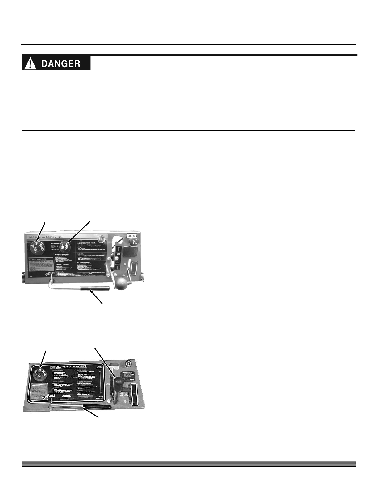
Operating the Chipper Attachment
It may be helpful to familiarize yourself with the features on your Machine by reviewing Figure 1 in Chapter 2 before beginning the
steps outlined in this chapter. The instructions in your DR Field and Brush Mower Safety and Operating Instructions Manual
indicate that the engine will shut off if you release the Operator Presence Lever. Although this is true with some attachments, it
does not apply to the Chipper Attachment when installed properly. The Operator Presence override feature of the Chipper
Harness that you installed in Chapter 2 will enable you to operate the Chipper even though the Operator Presence Lever is not
held down as long as the Key Switch in the “Run w/light” position. When the Chipper is disconnected from the Field and Brush
Mower, the Operator Presence lever will function normally for other
Run w/Light
Switch Setting
Blade Control
Knob
attachments.
Starting the Chipper
NEWER FIELD AND BRUSH MOWER
Figure 28
Run w/Light
Switch Setting
Blade Control
Lever
Shift Lever
NOTE: Remove any debris buildup from the machine before every use of the
Chipper.
1. Ensure that the Belt Release Lever on the Chipper Attachment is in the
“Tighten” position.
2. Set the Parking Brake on your DR Field and Brush Mower.
3. Make certain that the Shift Lever is in the Neutral position and the Blade
Control Knob (newer Field and Brush Mower) is pushed down to the
“Disengaged” position (Figure 28).
NOTE: For an older Field and Brush mower, without a Blade Control Knob, you will
need to move the Blade Control Lever back towards you to the “Disengaged”
position (Figure 29).
4. Start the engine in accordance with the Safety & Operating Instructions for
your DR Field and Brush Mower and make sure the Key Switch is in the
“Run w/light” position.
5. After the engine has warmed up, set the Throttle to Run.
NOTE: Always operate the Field and Brush Mower at maximum RPM when
chipping.
6. To start the Chipper, pull up on the Blade Control Knob (newer Field and
Brush Mower) to the “Engaged” position (Figure 28).
NOTE: For an older Field and Brush mower, without a Blade Control Knob, you will
need to move the Blade Control Lever forward away from you to the “Engaged”
position (Figure 29).
OLDER FIELD AND BRUSH MOWER
Figure 29
14 DR
Shift Lever
®
CHIPPER ATTACHMENT
Page 15

A
Stopping the Chipper
Discharge
rea
Operator
Zone
Operator
Zone
Hopper
Top View
Chipper
1. Push in the Blade Control Knob (newer Field and Brush
Mowers) or move the Blade Control Lever to the
“Disengaged” position (older Field and Brush Mowers) on
the Control Panel, return the Throttle to Idle and turn off
the Field and Brush Mower engine. Be sure to remove the
Key from the Field and Brush Mower for safety.
NOTE: When removing the DR CHIPPER ATTACHMENT from
the DR Field and Brush Mower, be sure to disconnect the Machine
harness at the interface between the Chipper Attachment and the
DR Field and Brush Mower.
Operation Notes
Field and
Brush Mower
Visually check the Chipper Knife for damage before each use
of the machine. See “Visual Inspection of the Chipper Knife
(before each use)” in Chapter 4 for info on accessing the
Chipper Knife (remove the Front Knife Access Cover only).
Always operate the Engine at full speed when chipping.
Only operate the DR CHIPPER ATTACHMENT from the
Operator Zone (Figure 30).
Figure 30
Keep proper balance and footing while operating the DR
CHIPPER ATTACHMENT.
ALWAYS push in the Blade Control Knob (newer Field and Brush Mower) or move the Blade Control Lever to the “Disengaged”
position (older Field and Brush Mowers) and stop the engine when leaving the Operating Zone or when moving the machine.
Never move the Machine while the Flywheel is turning.
Processing Material
Always wear protective goggles or safety glasses with side shields while chipping to protect your eyes from possible thrown
debris.
Avoid wearing loose clothing or jewelry, which might catch on moving parts or the material fed into the chipper hopper.
We recommend wearing gloves while chipping. Be sure your gloves fit properly and do not have loose cuffs or drawstrings.
Wear shoes with non-slip treads when using your chipper. If you have safety shoes, we recommend wearing them. Do not
use the machine while barefoot or wearing open sandals.
Wear long pants while operating the DR CHIPPER ATTACHMENT.
Use ear protectors or ear plugs rated for at least 20 dba to protect your hearing.
The chipper hopper must be securely bolted to your DR CHIPPER ATTACHMENT and the blowback shield in place before
using the machine.
Use common sense when using the machine. Learn to recognize the change in sounds when overloaded. Disengage the blade at
the control panel of the Field and Brush Mower immediately if the machine becomes jammed to prevent damage to the drive
system.
CONTACT US AT www.DRpower.com 15
Page 16

The Chipper is designed to accept wood only. The Chipper Knife mounted on a revolving flywheel turns branches fed into the
Chipper Hopper into “chips”. The Chipper can chip branches ranging in size up to 3-1/2" in diameter. Cut your branches into
manageable lengths before feeding them into the Chipper Hopper.
Your DR CHIPPER ATTACHMENT can process dry or green wood up to 3.5" in diameter.
Green wood will process quicker and easier than dry wood.
Softwood processes easier than hardwood.
Your operator experience will teach you how different types of wood will chip and how fast you can process them.
When chipping branches, sometimes a tail will develop at the end of a branch. To avoid this, rotate the branch while feeding it
into the Chipper Hopper.
Rotating the branch as you feed it into the machine will improve chipping performance.
Use caution with small diameter green saplings and branches less than 2" in diameter. Chip these grouped or bundled
together to provide support for each other. If the material is 2" or larger, feed only one at a time into the Chipper Hopper.
Make sure the DR CHIPPER ATTACHMENT finishes processing material in the Hopper before pushing down the Blade Control
Knob (newer machines) or moving the Blade control Lever to “Disengaged” (older machines) and shutting the engine off.
Do not force material into the Chipper. If the machine does not chip well, the Chipper Knife may need sharpening or
replacement, or the gap between the Knife and the Wear Plate needs adjusting. See “Removing, Replacing and Adjusting the
Chipper Knife and Wear Plate” in Chapter 4.
Extremely hard knots will not process very well. Use the next branch to be chipped to push any short stubs that have not self-
fed through the Chipper.
Cut the material to be chipped into manageable lengths of no more than five or six feet long before chipping them.
Overloading the Chipper Hopper will cause the rotor speed to decrease. If you hear the engine RPM of the Field and Brush
Mower decreasing, stop feeding material into the Chipper Hopper until the engine has returned to full speed.
Never throw remaining stubs or knots into the chipper hopper; damage will result.
To Free a Jammed Flywheel
Disengage the blade at the control panel of the field and brush mower. Shut down the engine, wait for all moving parts to come to
a complete stop, remove spark plug wire(s) keeping it away from the spark plug(s) to prevent accidental starting, then wait 5
minutes before performing maintenance procedures or inspection on the chipper.
Tools Needed:
Two 1/2" Wrenches
Disassemble:
1. Remove any material left in the Chipper Hopper.
Never pry against the scroll weldment when removing the deflector or at any other time. This will cause damage to the machine.
16 DR
®
CHIPPER ATTACHMENT
Page 17

Figure 31
Scroll
Weldment
Bolts and
Locknuts
Discharge
Chute
2. Remove the two Bolts, four Washers and two Locknuts that secure the
Deflector to the Chipper Assembly with two 1/2" wrenches and then remove
the Deflector (Figure 31).
3. Check to see if the Deflector opening is clogged. If it is, clear it with a
branch.
NOTE: You may need to remove the Belt from the Chipper Pulley so the Flywheel is
allowed to turn freely for the next step.
4. With a wooden stick, loosen and remove any material left in the Chipping
Chamber and make sure the Flywheel turns freely with the stick.
Reassemble:
1. Position the Deflector onto the Chipper Assembly and secure with two Bolts,
four Washers (one on each side) and two Locknuts using two 1/2" wrenches
(Figure 31).
2. Reconnect the spark plug wire, start the DR Field and Brush Mower engine,
engage the Blade Control Knob; allowing the remaining material in the
Chipping Chamber to discharge.
3. If the Chipping Chamber doesn’t clear and the flywheel is still jammed,
repeat above process.
NOTE: Be certain the Chipping Chamber is clear before trying to process more
material into the Chipper Hopper.
CONTACT US AT www.DRpower.com 17
Page 18

Chapter 4: Maintaining The DR CHIPPER ATTACHMENT
For DR Field and Brush Mower maintenance, please refer to the Safety and Operating Instructions Manual that came with your
DR Field and Brush Mower.
Regular Maintenance Check List
Disengage the blade at the control panel of the Field and Brush Mower. Shut down the engine, wait for all moving parts to
come to a complete stop, remove spark plug wire keeping it away from the spark plug to prevent accidental starting, then
wait 5 minutes before performing maintenance procedures or inspection on the chipper.
NOTE: Consider that the service intervals shown are the maximum under normal operating conditions. Increase frequencies under
extremely dirty or dusty conditions.
Procedure
Check General Equipment Condition
Check that the Flywheel turns freely (with a long stick only)
Visually inspect Knife for damage
Check Knife and Wear Plate for Sharpness
Check Knife and Wear Plate Attachment Screws
Check Flywheel Bearing Collar Set Screws
Check Knife to Wear Plate Gap
Lubricate Flywheel Bearings
Check Belt Condition
Replace Drive Belt
Before Each Use Every 8-10
Hours
▲
▲
▲
▲
▲
▲
▲
▲
▲
▲
Every 40
Hours
Grease Fittings
Your DR CHIPPER ATTACHMENT was greased at the Factory. The operator needs to periodically lubricate the two Bearings of
the Chipper Assembly.
Disengage the blade at the control panel of the Field and Brush Mower. Shut down the engine, wait for all moving parts to come
to a complete stop, remove spark plug wire keeping it away from the spark plug to prevent accidental starting, then wait 5 minutes
before performing maintenance procedures or inspection on the chipper.
Tools and Supplies needed:
Flexible hose grease gun
Lithium grease
Clean cloth
5/32" Allen Wrench
Thread Lock (if needed)
1. Unscrew the Hand Knob and remove the Belt Guard.
18 DR
®
CHIPPER ATTACHMENT
Page 19

2. Wipe all dirt, etc., from the grease fittings with a clean cloth (Figure 32).
3. Apply no more than three pumps of quality general-purpose lithium grease
with a hand-pumped grease gun to each Bearing Grease Fitting, one on
either side of the Chipper Assembly.
Bearing
Over lubrication can damage the bearings.
4. Check the Set Screws for tightness. If they are not tight they should be
removed, apply Thread Lock
to the threads, then reinstall and tighten the
Set Screws.
5. Position the Belt Guard and secure with the Hand Knob.
Removing, Replacing and Adjusting the Chipper Knife and Wear
Plate
INSPECTING THE CHIPPER KNIFE AND WEAR PLATE
Routine inspection of the Chipper Knife and Wear Plate will ensure that your DR
CHIPPER ATTACHMENT is operating at full efficiency (see “Regular
Maintenance Checklist” at the beginning of this Chapter). Operating with a
worn or damaged Chipper Knife or Wear Plate will cause extreme stress and
vibration to the machine and make chipping difficult for the operator.
The Knife should be visually checked for damage before each use. The first
procedure (“Routine Visual inspection of the Chipper Knife”) describes a quick
way to check the Knife only through the Access Cover. The second procedure
(“Visual inspection of the Chipper Knife and Wear Plate”) is for a more detailed
look at the condition of the Knife and Wear Plate by removing the Hopper.
Grease
Fitting
Front Chipper Bearing
Grease
Fitting
Rear Chipper Bearing (under Belt Guard)
Figure 32
Set
Screw
Bearing
Set
Screw
Routinely check the chipper knife for sharpness. Using a dull knife will decrease performance and cause excessive vibration
that will cause damage to the DR CHIPPER ATTACHMENT.
Routinely check the wear plate for a sharp square edge. Using a rounded or chipped wear plate will decrease performance
and cause excessive vibration that will cause damage to the DR CHIPPER ATTACHMENT.
Disengage the blade at the control panel of the Field and Brush Mower. Shut down the engine, wait for all moving parts to come
to a complete stop, remove spark plug wire keeping it away from the spark plug to prevent accidental starting, then wait 5 minutes
before performing maintenance procedures or inspection on the chipper.
VISUAL INSPECTION OF THE CHIPPER KNIFE (before each use)
Tools Needed:
5/16" Wrench
CONTACT US AT www.DRpower.com 19
Page 20

g
A
g
A
f
Screws
Front
ccess
Cover
ure 33
Fi
1. Remove the four Screws that secure the Front Access Cover with a 5/16"
wrench and remove the Access Cover (Figure 33).
NOTE: You may need to remove the Belt from the Chipper Pulley so the Flywheel is
allowed to turn freely for the next step.
2. Rotate the Flywheel with a long stick until the Knife is visible.
3. If the Knife has visible nicks or damage it must be sharpened or replaced
(see “Removing and Replacing the Chipper Knife” in this chapter).
4. If the Knife does not appear to have any damage, replace the Access Cover
and secure with four Screws using a 5/16" wrench.
Fi
ure 34
Wear
Plate
Figure 35
Chipper
ssembly
Self Tapping
Screws
Hopper
Bolt, Washer and
Locknut (4 places)
Chipper
Knife
VISUAL INSPECTION OF THE CHIPPER KNIFE AND WEAR PLATE (every 8-10
hours)
Tools Needed:
1/2" Wrench
1. Use a 1/2" wrench to remove the four Carriage Bolts, Washers and Locknuts
that support the Hopper to the Chipper Assembly (Figure 34).
2. Remove the Hopper from the Chipper Assembly.
NOTE: You may need to remove the Belt from the Chipper Pulley so the Flywheel is
allowed to turn freely for the next step.
3. Use a long stick to rotate the Flywheel until the Knife is next to the Wear
Plate.
4. Closely inspect the Chipper Knife and Wear Plate for nicks or dull (rounded)
edges (Figure 35).
5. If necessary, sharpen or replace the Chipper Knife and/or Wear Plate per the
following procedures.
6. Replace the Hopper when finished.
Removing and Replacing the Chipper Knife
Tools and Supplies Needed:
5/16" Wrench
3/16" Allen wrench
1/2" Socket
Awl or Sharp Tool
Gloves
Be careful and wear gloves when working near the chipper knife. The knife
edge can cut you if you come in contact with it.
1. Remove the Hand Knob and then remove the Belt Guard.
2. Using a 5/16" Wrench, remove the Self -Tapping Screws and remove both
Rear Knife Access
Cover (one on the
ront side also)
Figure 36
20 DR
®
CHIPPER ATTACHMENT
Knife Access Covers from the front and back of the Chipper Assembly
(Figure 36).
NOTE: You may need to remove the Belt from the Chipper Pulley so the Flywheel is
allowed to turn freely for the next step.
Page 21

A
3. Rotate the Flywheel using a long stick until the three countersunk Allen
Screws and Locknuts attaching the Knife to the Flywheel are visible through
the Access Openings (Figure 37).
4. Clean out the heads of the Allen Screws with an Awl or Sharp Tool.
5. Insert a 3/16” Allen Wrench into the head of a screw.
6. While holding the Allen Wrench, remove the Locknut using a 1/2" socket.
Flywheel
Slot
Chipper Knife
(sharp edge facing up and
towards you)
7. Repeat Steps 5 and 6 for the remaining two Allen Screws.
8. Remove the dull or damaged Knife and visually inspect the Flywheel Slot and
Knife mounting area and be sure they are clean and that the replacement
Countersunk
llen Screws and
Locknuts
Knife will be able to mount flush against the Flywheel.
Figure 37
If the flywheel surface is not cleaned properly and the chipper knife is not mounted flush on the flywheel, the knife could crack
when the hardware is tightened.
9. Install a new or sharpened Knife as shown (Figure 37) with the Knife edge facing up and towards you and finger tighten the
Allen screws and Locknuts (use the new hardware supplied with a new Knife kit) to hold the Knife to the Flywheel.
10. Using a 3/16” Allen wrench and a 1/2” socket, tighten the center Screw and Locknut, tighten the outer Screw and Locknut,
then tighten the inner Screw and Locknut.
11. Double-check that all three Locknuts on the Allen Screws are tight.
12. Reinstall the two Access Covers.
13. Replace the Belt Guard.
14. Check and if needed adjust the gap between the Knife and Wear Plate (See “
Plate Gap
” in this Chapter).
Checking and Adjusting the Knife to Wear
Removing and Replacing the Wear Plate
Tools Needed:
7/16" wrench
1. Remove the Hopper (See “
Inspecting the Chipper Knife and Wear Plate”
Chipper
Knife
in this Chapter).
2. Use a 7/16" wrench to remove the three Locknuts and Carriage Bolts that
attach the Wear Plate to the Chipper Assembly and then remove the Wear
Plate (Figure 38).
3. Install the new Wear Plate and secure with the Carriage Bolts and Locknuts.
NOTE: The Gap between the Knife and Wear Plate must be adjusted whenever the
Wear Plate is removed. See the following instructions.
Checking and Adjusting the Knife to Wear Plate Gap
Carriage Bolt
and Locknut
Figure 38
Wear
Plate
When you replace the Knife or Wear Plate, you must check and set the clearance between the Knife and Wear Plate. Set this
clearance or gap to 1/16" by using the Gap Tool that is supplied with the Chipper and with a new Knife Kit. If the gap between the
Wear Plate and the Knife is not set correctly, you will have excessive vibration when chipping and the Knife will seem to be dull.
The Wear Plate should have a square edge and be free of dents or gouges. The Wear Plate can be hand sharpened (see steps
below). Be careful not to overheat it during the sharpening process. This will change the characteristics of the steel and you will
then have to replace the Wear Plate (see “Wear Plate Sharpening” in this chapter).
CONTACT US AT www.DRpower.com 21
Page 22

Disengage the blade at the control panel of the Field and Brush Mower. Shut down the engine, wait for all moving parts to come
to a complete stop, remove spark plug wire keeping it away from the spark plug to prevent accidental starting, then wait 5 minutes
before performing maintenance procedures or inspection on the chipper.
Wear
Plate
Figure 39
Knife Gap
Gauge
Knife
Checking the Knife to Wear Plate Gap
Tools Needed:
Gap Gauge (provided with Chipper)
1. Remove the Hopper (See “Inspecting the Chipper Knife and Wear Plate” in
this Chapter).
NOTE: You may need to remove the Belt from the Chipper Pulley so the Flywheel is
allowed to turn freely for the next step.
2. Use a stick to rotate the Flywheel until the Knife is positioned next to the
Wear Plate.
3. Slide the Knife Gap Gauge in between the Knife and Wear Plate to check the
clearance (Figure 39).
o If the Knife Gauge slides freely, with no resistance and a lot of extra
space, the Wear plate must be adjusted.
o If the Knife Gauge will not slide down between the Knife and Wear
Plate, the Wear Plate must be adjusted.
o If the Knife Gauge slides in between the Knife and Wear Plate with
some resistance felt against them both or slides in between with
no noticeable space, then the Wear plate is properly adjusted.
4.
Install the Hopper when finished.
Carriage Bolt
and Locknut
Figure 40
Wear
Plate
Figure 41
22 DR
Wear
Plate
Chipper
Knife
®
CHIPPER ATTACHMENT
Flywheel
1/16" Gap
(thickness of
Gap Gauge)
Adjusting the Knife to Wear Plate Gap
Tools Needed:
7/16" wrench
Gap Gauge (provided with Chipper)
1. To adjust the Wear Plate Gap, loosen the three Nuts on the Carriage Bolts
with a 7/16" wrench just enough so the Wear Plate will move but still have a
slight resistance. Now you can slide the Wear Plate up or down (in or out)
to achieve the correct gap setting (Figure 40 and 41).
2. Take the Gap Gauge and slide it between the Knife and Wear Plate (Figure
39). Adjust the Wear Plate against the Knife Gauge and tighten the outside
Locknut, check the gap, tighten the inside Locknut and then the center
Locknut.
3. Check the adjustment as described in the “Checking the Knife to Wear Plate
Gap” in the previous section.
4. Reinstall the Hopper when finished.
Page 23

Chipper Knife Sharpening
After any knife or wear plate maintenance or adjustment, rotate the chipper flywheel by using a wooden stick and watch and listen
carefully for any unusual noises, clicking or vibration. If you detect any of these, inspect the machine for damage, or any loose
parts. Repair or replace any damaged parts and tighten any loose parts before starting the DR CHIPPER ATTACHMENT.
You should never attempt to sharpen the Chipper Knife freehand.
It is extremely important to consistently maintain the 45-degree angle for
proper performance (Figure 42).
Excessive heat generated during the sharpening process will damage Knives
and weaken the metal. Be sure not to overheat the Knife during sharpening
because it will shorten the life of the Knife.
Chipper
Knife
Take the Chipper Knife to a machine shop for proper sharpening.
45°
How many times a Knife can be sharpened is determined by how much
material needs to be taken off to sharpen or to compensate for dents or
gouges.
Figure 42
A new Chipper Knife has 5/16" measurement between the short side bevel edge and the Knife mounting holes (Figure 43 “New
Knife”).
The knife should never be sharpened to the extent that more than 3/32" is taken off this measurement.
Once this measurement is below 7/32" (see Figure 44 “Sharpened Knife”), or if you are unable to remove dents or gouges with
these guidelines, replace the Knife.
Knife Mounting Hole
Short Side Beveled Edge
New Knife
5/16" 5/16"
Short Side Beveled Edge
Figure 43
Sharpened Knife
Figure 44
7/32" 7/32"
CONTACT US AT www.DRpower.com 23
Page 24

Wear Plate Sharpening
Figure 44
Belt
Guard
Hand
Knob
File this
edge flat
Front View
Wear
Plate
Side View
Carriage
Bolt
Guides
The Wear Plate edges become rounded and chipped during use and must be
squared off to ensure efficient operation.
Tools Needed:
Flat File
Straightedge
1. Secure the Wear Plate in a vise.
2. File the edge of the Wear Plate to take out any nicks and to square
rounded edges (Figure 44).
3. Check with a Straightedge to ensure that the Wear Plate edge is flat and
straight.
NOTE: If the Wear Plate is filed enough times that the proper gap between the
Knife and Wear Plate can not be set with the Gap Gauge, you will need to
replace the Wear Plate.
Replacing the Belt
1. Remove the Hand Knob from the top of the Belt Guard and remove the
Guard (Figure 45).
2. Make sure the Belt Release Lever is in the “Release” position (Figure 46).
3. Rotate the Chipper Pulley as you slid the belt from it.
Figure 45
Tighten Belt Position,
Left and Up
Belt Release
Lever
Figure 46
4. Remove the Belt from the Field and Brush Mower Pulley.
Release Belt
Position,
Down and
Right
24 DR
®
CHIPPER ATTACHMENT
Page 25

y
ys
t
5. Position the Belt onto the Field and Brush Mower Pulley (Figure 47) and then
route it over the two Idler Pulleys and up around the Chipper Pulley (Figure
48).
NOTE: Ensure that the “V” portion of the Belt rests properly into the Idler Pulleys.
6. Move the Belt Release Lever to the “Tighten” position.
NOTE: There is a slot in each of the bottom Tabs of the Belt Guard. These slots must
slide over the Carriage Bolt Guides that are mounted to the inner Frame
Supports of the Chipper (Figure 45).
7. Reinstall the Belt Guard and secure with the Hand Knob.
Figure 47
Carriage
Bolt for
belt guard
mounting
(one on
each side)
Field and
Brush Mower
Pulle
Idler Pulleys
Chipper Idler
Pulleys
Twist Belt to
Engage “V”
Properly into
Idler Pulle
Chipper
Sprocke
Twist Belt so “V”
Engages Properly into
Chipper Sprocket
Belt
Belt
Figure 48
CONTACT US AT www.DRpower.com 25
Page 26

Chapter 5: Troubleshooting
Disengage the blade at the control panel of the Field and Brush Mower. Shut down the engine, wait for all moving parts to come
to a complete stop, remove spark plug wire keeping it away from the spark plug to prevent accidental starting, then wait 5 minutes
before performing maintenance procedures or inspection on the chipper.
Most problems are easy to fix. Consult the Troubleshooting Table below for common problems and their solutions. If you
continue to experience problems, contact us at www.DRpower.com or call 1-800-DR-OWNER (376-9637) for support.
Troubleshooting Table
SYMPTOM POSSIBLE CAUSE
Chipping action seems
too slow or flywheel
stalls.
The belt frays or rolls
over the pulley.
- Belt burns.
- Flywheel won’t turn.
The machine has
excessive vibration.
When chipping, the log
seems to vibrate
excessively and
“hammers” my hands.
Chipper Knife is hitting
the Wear Plate.
The engine speed is too slow causing the belt to slip. Run the engine at full throttle.
Check for a loose or damaged Drive Belt; tighten or replace. See Chapter 4.
Check for a dull or damaged Knife; sharpen or replace the Knife. See Chapter 4.
The rotor Drive Pulley groove may be nicked. Check the Drive Belt for wear and hard spots. File
off any nicks on the pulley.
The Drive Belt may be stretched; replace it. See Chapter 4.
Immediately disengage the Blade Control Knob, stop the engine and disconnect the spark plug
wire.
Turn the Flywheel with a wooden stick to be sure it turns freely.
Check for a loose Drive Belt. See Chapter 4.
Remove any built up debris from the Chipper Hopper Inlet and Discharge Chute.
Check for a dull or damaged Knife; sharpen or replace the Knife. See Chapter 4.
The Knife is not properly seated on the flywheel. Loosen the Knife mounting screws, reset the
Knife and tighten the screws. Also, check the Knife to Wear Plate Gap. See Chapter 4.
If the machine still exhibits excessive vibration, contact us at www.DRpower.com or call 1(800)
DR-OWNER (376-9637) for assistance.
The Knife is dull; sharpen or replace it. See Chapter 4.
The gap between the Knife and Wear Plate is too great; adjust the Gap. See Chapter 4.
Check Engine rpms; run Engine at full throttle when chipping.
The gap between the Knife and the Wear Plate is set incorrectly; adjust the Knife to Wear Plate
Gap. See Chapter 4.
If adjusting the gap did not fix the problem, contact us at www.DRpower.com or call 1(800) DR-
OWNER (376-9637) for assistance.
26 DR
®
CHIPPER ATTACHMENT
Page 27

Disengage the blade at the control panel of the Field and Brush Mower. Shut down the engine, wait for all moving parts to come
to a complete stop, remove spark plug wire keeping it away from the spark plug to prevent accidental starting, then wait 5 minutes
before performing maintenance procedures or inspection on the chipper.
Troubleshooting Table (Continued)
SYMPTOM POSSIBLE CAUSE
Engine will not run
unless Operator
Presence lever is held
down.
Is the key switch turned to the Run w/light position? Turn the Key Switch to the Run w/light
position.
Is the Belt Engagement Lever in the “Tighten” position? Move the Lever to the “Tighten”
position.
Check for loose or disconnected Connectors (operator presence, field and brush mower to
Chipper, light switch, and relay). Properly connect Connectors.
Is Ground Wire properly grounded? Clean terminal and tighten Ground Wire hardware.
Is relay working properly? Make sure all connections are made at all areas of the Wire Harness.
With your hand on the relay, turn the Key Switch to the light accessory position. If you feel a
click then the relay is probably OK. If there is no click in the relay may need to be replaced.
If the Engine still will not run unless the Operator Presence is held down please contact us at
www.DRpower.com or call toll-free at 1(800) DR-OWNER (376-9637) for assistance.
CONTACT US AT www.DRpower.com 27
Page 28

Chapter 6: Parts Lists and Schematic Diagrams
Parts List – FRAME ASSEMBLY
NOTE: Part numbers listed are available through DR Power Equipment.
Ref# Part# Description
01 241821 Label, Warning Rotating Parts, 4.5"
X 3"
02 143661 Knob, 5/16-18
03 247981 Label, Do Not Move
04 110761 Nut, Nylon Lock, 5/16-18
05 247751 Belt, 5L830K, 5/8 X 83"
06 247761 Pulley, V, 7.5" OD
07 142291 Key, Square, 1/4 X 1-1/4
08 112411 Washer, Flat, 5/16", USS
09 145291 Bolt, Carr, 5/16-18 X 3/4"
10 263891 Deflector w/ Labels
11 241811 Label, Danger, Discharge Chute 4" X
3"
12 241831 Label, High Speed Discharge 4" X 3"
13 111321 Bolt, HCS, 5/16-18 X 4", GR5
14 263901 Base, Weldment w/ Labels
15 241801 Label, Danger, Read Manual 4" X 2"
16 256571 Pulley, Idler
17 184511 Spacer, .39" ID, .63" OD, .52" LG
18 123341 Bolt, HCS, 3/8-16 X 1- 3/4", GR5, ZP
19 247781 Idler Arm, ATM Chip
20 247791 Spring, Extension, 4", .135 " Wire
Dia
21 248021 Bolt, Shldr, 5/16-18, 3/8" Dia X 7/8"
22 110751 Nut, Nylon Lock, 3/8-16
23 111521 Bolt, HCS, 3/8-16 X 1", GR5, ZP
24 247831 Bracket, Belt Release Lever
25 247801 Lever, Belt Release, ATM Chip
Ref# Part# Description
26 247811 Grip, Handle
27 264401 Leg, Base, ATM Chip
28 263941 Guard Assembly, ATM Chipper, Belt
w/ Labels
29 256151 Support, Leg
30 123211 Bolt, HCS, 5/16-18 X 3/4", GR5, ZP
31 118731 Nut, Nylon Lock, 10-24
32 124371 Label, American Flag, 2.75" X 1.75"
33 164891 Switch, Plunger Retrofit
34 245271 Wire Harness, Chipper OPC
35 247991 Label, Belt Release
36 263911 Plate, Lever Lock w/ Labels
37 180991 Screw, Phillips 10-24
38 247941 Shield, Blow-Back
39 247931 Support, Blow-Back Shield
40 200141 Mount Plate, Blow-Back Shield
41 114781 Screw, PH 10-24 X 5/8"
42 247961 Label, Danger, Death/Injury 7.75" X
4"
43 263921 Hopper Assembly, w/ Labels
44 263931 Chipper Basic Weldment w/ Labels
45 256131 Bracket, Belt Guard
Not Illustrated
112141 Cable Tie, 7-1/2" L
245261 Wire Harness, ATM Chipper, OPC
28 DR
®
CHIPPER ATTACHMENT
Page 29

Schematic – FRAME ASSEMBLY
CONTACT US AT www.DRpower.com 29
Page 30

Parts List – CHIPPER BASIC
NOTE: Part numbers listed are available through DR Power Equipment.
Ref# Part# Description
01 110761 Nut, Nylon Lock. 5/16-18
02 256311 Bearing, 2 Bolt, 1-3/16"
03 254521 Shim, .120"
04 183011 Ring, Retaining, 1-3/16"
05 229101 Nut, Hex, 1/2-13", GR5, ZP
06 112421 Washer, Flat Lock, 1/2", USS
07 167981 Cover, Access
08 155121 Screw, Self Tap, 10-32 X 1"
09 247891 Side Plate Weldment w/ Labels,
Drive
10 229091 Bolt HCS, 1/2-13 X 1-1/2"
11 241991 Label, Warning, Stop & Wait, 2.5" X
3"
12 247871 Chipper Disk Assembly, w/ Knife
13 247971 Label, Warning, Access Plate, 4" X
3"
14 263981 Cover w/ Labels, Access
Ref# Part# Description
15 192021 Label, Dr Logo, 4" Round 4 Color
16 110731 Nut, Nylon Lock, 1/4-20
17 112371 Washer, Flat, 10-24 X 5/8"
18 186041 Plate, Wear
19 157471 Bolt, Carr, 1-4-20 X 1"
20 222131 Bolt HCS, 5/16-18 X 3-5/8", GR5, ZP
21 263961 Side Plate Weldment w/ Labels,
Hopper
22 263971 Scroll Weldment w/ Label
23 183131 Spacer, Scroll Tube
Not Illustrated
197091 Gauge, Knife Gap
200481 Knife Kit, CPR
30 DR
®
CHIPPER ATTACHMENT
Page 31

Schematic – CHIPPER BASIC
CONTACT US AT www.DRpower.com 31
Page 32

Daily Checklist for the DR CHIPPER ATTACHMENT
To help maintain your DR CHIPPER ATTACHMENT for optimum performance, we recommend you follow this checklist each
time you use your Chipper.
Disengage the blade at the control panel of the Field and Brush Mower. Shut down the engine, wait for all moving parts to come
to a complete stop, remove spark plug wire keeping it away from the spark plug to prevent accidental starting, then wait 5 minutes
before performing maintenance procedures or inspection on the chipper.
NOTE: Please refer to the DR Field and Brush Mower Safety and Operating Instructions manual for its daily checklist.
[ ] BELT: Check the Belt for wear.
[ ] KNIFE and WEAR PLATE: Check the Knife and Wear Plate for tightness, nicks, wear and proper gap.
[ ] GENERAL CONDITION: Check the general condition of the machine, e.g.; nuts, bolts, welds, etc.
[ ] HOPPER: Check that there is no material left in the hopper before starting the Chipper.
[ ] BEARINGS: Check that Bearings have been greased.
End of Season and Storage
Disengage the blade at the control panel of the Field and Brush Mower. Shut down the engine, wait for all moving parts to
come to a complete stop, remove spark plug wire keeping it away from the spark plug to prevent accidental starting, then wait
5 minutes before performing maintenance procedure or inspection on the Chipper.
When not in use, your DR CHIPPER ATTACHMENT should be stored out of the reach of children.
NOTE: Please refer to the DR Field and Brush Mower Safety and Operating Instructions manual for its storage requirements.
Lubricate all grease fittings.
Check the Drive Belt for wear.
Check the Chipper Knife and Wear Plate for nicks and wear.
Clean any debris from the Hopper and Discharge Chute.
75 MEIGS ROAD, P.O. BOX 25, VERGENNES, VERMONT 05491
©2013 Country Home Products, Inc. All rights reserved 257241A
 Loading...