

Page 1
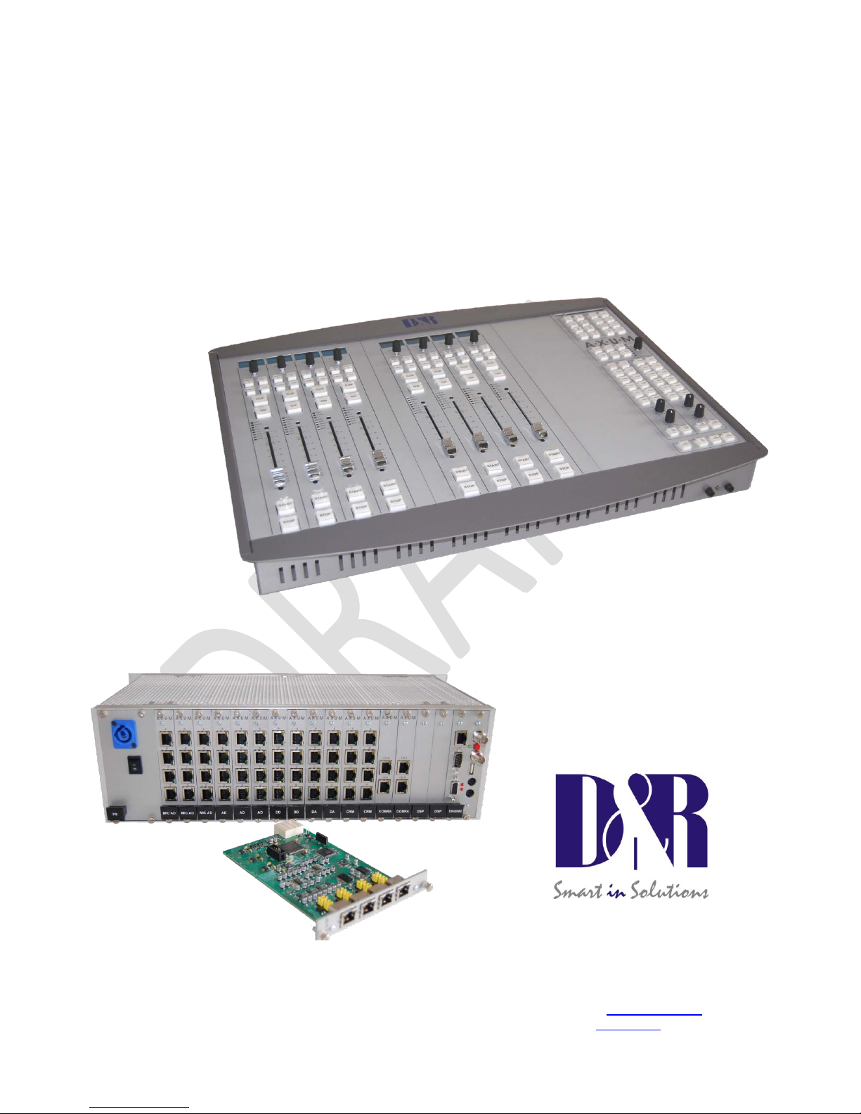
DIGITAL AUDIO MIXING SYSTEM
A·X·U·M
User Manual
D&R Electronica Weesp BV
Rijnkade 15B
1382GS Weesp
The Netherlands
Phone: +31 (0)294-418014
Fax: +31 (0)294-416987
Website:
http://www.d-r.nl
E-mail: info@d-r.nl
Version 2.5 - 2011-01-28
Page 2

Dear Customer,
Thank you for choosing the AXUM audio mixing system.
Specialists in the field of Radio/TV Broadcast and audio production designed the AXUM.
It is a system that is capable of working in a multitude of applications that need a
24-hour "On-Air"/Production system.
To be able to improve our products we always value suggestions once you ha ve b ecome familiar with
your system. We will certainly learn from your comments and very much appreciate you dropping us a
mail at
We are confident that you will be using the AXUM for many years to come, and wish you lots of
success in your business.
And… please take some time to read this manual first to avoid unnecessary questions to yourself and
to us.
With kind regards,
Duco de Rijk
President
D&R ELECTRONIC A WEESP B.V.
Rijnkade 15B
1382 GS Weesp
The Netherlands
Phone: +31 294 418014
Fax: +31 294 416987
Website:
http://www.d-r.nl/
E-mail:
Page 3

A·X·U·M User Manual Version 2.5 - 2011-01-28
AXUM from D&R - Phone: +31 294 418014 - E-Mail: info@d-r.nl - 3 -
1 Table of contents
1 TABLE OF CONTENTS 3
2 PACKAGE CONTENTS 5
3 INTRODUCTION 6
4 SYSTEM OVERVIEW 7
4.1 SYSTEM PARTS 7
4.2 COMMUNICATION 9
4.3 FEATURES AND HIGHLIGHTS 10
4.4 PRINCIPLE OF OPERATION 11
4.4.1 AXUM system 11
4.4.2 Mixing console 11
5 CONTROL SURFACES 14
6 AXUM ENGINE 15
6.1 CONSOLE 1-4 CONFIGURATION 16
6.1.1 IP/Clock configuration 17
6.1.2 Global configuration 19
6.1.3 Mix buss configuration 20
6.1.4 Monitor buss configuration 21
6.1.5 Source configuration 22
6.1.6 Extern source configuration 24
6.1.7 Destination configuration 25
6.1.8 Talkback configuration 27
6.1.9 Processing presets 28
6.1.10 Module assignment 31
6.1.11 Module configuration 32
6.1.12 Mix/monitor buss pres ets 37
6.1.13 Console presets 40
6.1.14 Surface configuration 41
6.1.15 Rack configuration 43
6.1.16 Source pools 45
6.1.17 Preset pools 46
6.1.18 Users 47
6.2 SYSTEM CONFIGURATION 49
6.2.1 MambaNet node overview 50
6.2.2 Templates 52
6.2.3 Predefined node configuration s 53
6.2.4 Engine functions 54
6.2.5 Package versions 55
6.2.6 Change web accounts 56
7 SURFACE(S) WEBSITE 57
7.1 IP/CLOCK CONFIGURATION 58
8 BLOCK DIAGRAMS – MUST BE CREATED 60
9 I/O RACK DESCRIPTION 61
9.1 POWER SUPPLY 62
9.2 ENGINE 62
9.3 GPIO 65
9.3.1 GPI 65
9.3.2 GPI Active-state 65
9.3.3 GPO 66
9.3.4 GPO Time 66
9.3.5 GPO Active-state 67
10 AVAILABLE I/O RACK CARDS 68
10.1 MIC INPUT CARD 68
10.2 LINE INPUT CARD 69
10.3 DIGITAL IN/OUTPUT CARD (OPTIONAL SRC) 70
10.4 LINE OUTPUT CARD 71
10.5 CRM OUTPUT CARD 72
Page 4

A·X·U·M User Manual Version 2.5 - 2011-01-28
AXUM from D&R - Phone: +31 294 418014 - E-Mail: info@d-r.nl - 4 -
10.6 COBRANET IN/OUTPUT CARD 73
10.7 ADAT IN/OUTPUT CARD 74
10.8 HYBRID IN /OUTPUT CARD 75
10.9 FIREW IR E IN/OUTPUT CARD 76
10.10 DSP CARD 77
11 PATCH PANELS 78
11.1 19” PATCH PANELS / BREAKOUT PANELS 78
11.2 WIRING 79
11.2.1 GPIO/Remote 79
11.2.2 MIC 80
11.2.3 Phones 80
11.2.4 Stereo line input and output 81
11.3 STANDARD RJ45 WIRING 81
11.3.1 GPIO TTL/Relay selection 81
12 SPECIFICATIONS AXUM DIGITAL AUDIO SYSTEM 82
12.1 INPUT/OUTPUT CARDS 82
12.2 DSP PROCESSING 83
12.3 OVERALL 83
12.4 DIMENSIONS 84
13 LIST OF FIGURES 85
14 LIST OF TABLES 86
15 DECLARATION OF CONFORMI TY 87
16 PRODUCT SAFETY 88
17 DISCLAIMER 89
18 APPENDIX A - NETWORK DESIGN FOR AXUM 90
18.1 NETWORK LEVELS 90
18.2 AXUM NETWORK IMPLEMENTATION 90
18.2.1 MambaNet example 1 90
18.2.2 MambaNet example 2 91
18.3 NETWORK DESIGN (MAMBANET OVER LAYER 2) 91
18.3.1 Practical solution 1: Physical separated switches and IP router 93
18.3.2 Practical solution 2: single managed level 3 switch/router 94
18.3.3 Practical solution 3: Physical separated switches and PCs if IP router 95
18.4 NETWORK DESIGN (MAMBANET OVER LAYER 3) 96
18.5 IP SUBNETS AND IP ROUTES 97
18.6 REMOTE ACCESS 98
19 APPENDIX B – SURFACE SERVICE 99
19.1 PACKAGE VERSIONS 100
19.2 CHANGE PASSWORD 101
19.3 UPLOAD LOGO 102
20 APPENDIX C – ENGINE FUNCTIONS 103
20.1 MODULES 103
20.2 BUSSES 110
20.3 MONITOR BUSSES 112
20.4 CONSOLE 114
20.5 GLOBAL 117
20.6 SOURCES 118
20.7 DESTINATIONS 120
Page 5

A·X·U·M User Manual Version 2.5 - 2011-01-28
AXUM from D&R - Phone: +31 294 418014 - E-Mail: info@d-r.nl - 5 -
2 Package Contents
The AXUM package comes normally with the following parts inside:
• AXUM Getting started document
• AXUM System in the configuration you have ordered.
One or more 19” IO-Racks with the I/O, DSP and power supply cards.
Optional Control Surface(s) with external power supply.
Optional patch panels.
Optional RJ45 Shielded cables.
• AXUM user manual
WARNING: A network switch is not included but required to interconnection multiple system
parts and a laptop/PC for configuratio n . You may use any Ethernet switch for this purpose!
Page 6

A·X·U·M User Manual Version 2.5 - 2011-01-28
AXUM from D&R - Phone: +31 294 418014 - E-Mail: info@d-r.nl - 6 -
3 Introduction
This manual will give you an over view of the func tionality of the AXU M digital audio s ystem and all its
features. It is advis able t o read t his m anua l at l east on ce bef ore to uching an y contr ol, or e ven th inking
about hooking up the system. We know that this is actually the f ir st thing you want to do, but p lease d o
not and discipline yourself to read the manual first.
The manual gives al l sorts of valuable inform ation befor e getting star ted and it saves you from getting
all sorts of questions. After installing this manual can be used as a reference.
In the first chapter, we will give you an overview of the AXUM and its features.
This way, you have an impression on how to implement the system in your application.
The next chapters will deal with interconnecting the various parts of the system and its external
interfacing with your equipm ent
When installing and wiring the AXUM, you can finalize its interfacing with the instructions in the
following chapters.
After installation, you will have a very complete m ixer with a human interface that is very logical and
intuitive.
Page 7

A·X·U·M User Manual Version 2.5 - 2011-01-28
AXUM from D&R - Phone: +31 294 418014 - E-Mail: info@d-r.nl - 7 -
4 System overview
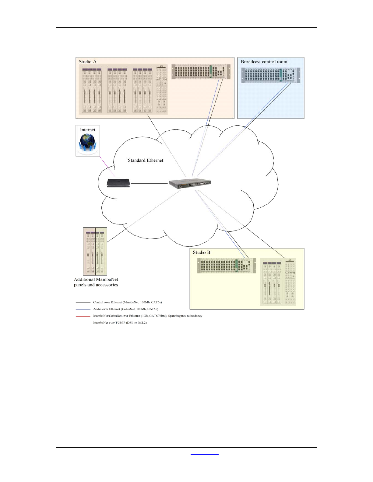
The Axum is a dig ital modular aud io system that can solv e your digital mixing/ro uting requirem ents in
your broadcast studio or in your complete broadcast facility. The m odular system can be used in all
your mixing/routing applications like on-air broadcast, self-op, production and voice tracking.
4.1 System parts
To make a functional mixing console you require at least a 19” rack with a DSP card (32 stereo
channels), the desired I/O cards and a control surface that can control all the mixing power. The
connection between the 19” rack(s) and control surface(s) rely on a network protocol that is been
called MambaNet.
MambaNet works on Ethernet la yer 2, there for no IP-addresses have to be setup f or the ‘real-time’
functionality.
WARNING: Do not connect multiple AXUM engines/racks in the same Ethe rnet network (Layer
2)
To connect surface( s) and 19” rack(s) you can built on this k nown Ethernet standard with comm on
switches till advanced m anaged switches with all the s ecurity solutions as there are STP (spann ing
tree protocol), Trunking etc.
For (remote) configuration the well known webbro wser is used to access the cons oles webserver. Of
course this happens on a IP-based level of communication, which makes it possible to configure
system over the internet.
The defaults IP-addresses for configuration pages are:
http://192.168.0.200 for the configuration in main menu
http://192.168.0.23x for the controller surfac e configuration. (for the first surfac e set x to 4, for a
second surface set x to 5, etc).
To prevent other people to access the Axum configuration pages you need to logon.
The default logon is:
Username: service
Password: service
This account ma y change, which is explained in chapter Error! Reference source not found.Error!
Reference source not found. (Error! Reference source not found.).
Network specialists can find some more information in chapter 18 (Appendix A).
Page 8
A·X·U·M User Manual Version 2.5 - 2011-01-28
AXUM from D&R - Phone: +31 294 418014 - E-Mail: info@d-r.nl - 8 -
Figure 1: Basic system layout
Page 9

A·X·U·M User Manual Version 2.5 - 2011-01-28
AXUM from D&R - Phone: +31 294 418014 - E-Mail: info@d-r.nl - 9 -
4.2 Communication
All control comm unication takes place with MambaNe t and gives the surf ace flexibility and power to
the AXUM digital audio s ystem. To understand the AXUM digit al audio system it would help to k now
some principles of MambaNet.
MambaNet definitions:
- Objects
A fader, switch will have to trigger an action in the AXUM digital audio system. In MambaNet,
we call these faders and switches ‘objects’.
- Nodes
In the hardware the faders and switches are grouped on modular blocks (think of a single
PCB), such blocks are represented as ‘nodes’ in MambaNet.
- Engine
In the Axum digital system the engine is in fact your mixing console. The functions available in
the ‘engine’ can connect to one or more objects found in your network.
In practice, this means you can connect any surface element like switches and faders to any function
of your mixing console(s). From now on, you can design your own functionality at the control surface.
Information for manufacturers and developers is located at
http://www.mambanet.org, it is possible to
make your own communication with the mixing system; we have a MambaNet library available for
Windows (DLL) and Linux (lib).
For professional developers it is possible to buy a Manufacture ID from D&R so you are able to make
your own equipment compatible with th e MambaNet protocol. Secondly, local radio stations can use
manufacturer ID 0xFFFF for some custom implementations.
(All manufacturer IDs are unique except the 0xFFFF, which is free for ‘in-house’ implementation)
Figure 2: MambaNet logo
Page 10

A·X·U·M User Manual Version 2.5 - 2011-01-28
AXUM from D&R - Phone: +31 294 418014 - E-Mail: info@d-r.nl - 10 -
4.3 Features and highlights
Because the AXUM digital audio system is highly flexible, you can make many solutions for your
mixing and routing. To have an overview on the power of the Axum digital audio system we made a
list of the most important features and highlights:
• I/O Matrix of 1280x1280 with optional I/O Cards:
- MIC inputs and GPIO’s
- Line inputs and GPIO’s
- Digital in/outputs and GPIO’s
- Line outputs and GPIO’s
- CRM/Phones outputs and GPIO’s
- ADAT in/outputs
- CobraNet in/outputs
- Firewire in/outputs
- Hybrid in/outputs
• 32 stereo modules per DSP card.
- Gain
- Low cut
- 6 band full parametric EQ
- Voice processing
- one free FX DSP for future use.
• 32 busses, default configured if:
console 1 and 2 with each a:
- Stereo Program buss
- Stereo Sub buss
- 4x Stereo Aux buss
- Stereo Dump buss
- Stereo PFL buss
• Up to 4 DSP cards
- up to 128 stereo modules
- up to 16 monitor busses.
(for example it is possible to make 4 studios with one I/O rack, or even 2 studios of 16 stereo
modules and 2 stereo monitor busses with a single DSP card in your I/O rack…)
• Advanced preset system.
• Object oriented control protocol, MambaNet
• Configuration of the AXUM nodes using one web server
• Multiple redundancy solutions
• Remote configuration via HTTP and TCP/IP
• Remote control via MambaNet over UDP/IP and TCP/IP
• Standardized cabling with RJ45 (shielded for audio connections)
• Advanced security system based
• User database for identification
Page 11
A·X·U·M User Manual Version 2.5 - 2011-01-28
AXUM from D&R - Phone: +31 294 418014 - E-Mail: info@d-r.nl - 11 -
4.4 Principle of operation
4.4.1 AXUM syst em
The AXUM system will be build up around the matrix/router that gives a lot of routing flexibility. Up to 4
DSP cards can be inserted to create mixing power as requested. For example, you can create with
one AXUM system (equipped with one DSP card):
- A single mixing console with 32 stereo modules and 16 stereo busses
- Multiple mixing consoles (maximal 4), 3 consoles are used in our example:
1 consoles with 16 stereo modules and 6 stereo busses
1 consoles with 12 stereo modules and 6 stereo busses
1 console 4 stereo modules and 4 stereo busses
This makes clear we do not talk over a ‘mixing console’, the AXUM is an audio-platform!
Depending on the configuration, you can make your own studio console(s)/surface functionality. Al this
power is controlled and configured by the AXUM engine. This engine configuration is described in
detail later on.
4.4.2 Mixing console
As mentioned before the configuration is done within the Axum engine, now we will give a short
overview/introduction on the structure of the mixing console(s) platform solution of the engine.
For the configuration of the busses, monitor busses and modules you can setup to which console it
should belong (1-4). Finally the engine will extract a ‘assignment’ picture from this information which
shows clearly the console blocks.
Page 12

A·X·U·M User Manual Version 2.5 - 2011-01-28
AXUM from D&R - Phone: +31 294 418014 - E-Mail: info@d-r.nl - 12 -
4.4.2.1 Sources
Each module can receive audio from the matrix using so called ‘sources’. A source is given a name,
left/right physical input and some additional settings (think of phantom, pad, redlight settings). For
example if we make source ‘MIC1’ with phantom on we can route this to module 1 and/or module 13.
So the MIC 1 is used at console 1 but also at console 2 (or 3).
4.4.2.2 Destinations
Audio is sent to physical outputs by so called ‘destinations’. A destinations given a name, left/right
physical outputs and some additional settings (default audio-source, N-1 etc). For examples we make
destinations ‘Line out 1’ and ‘Dig out 1’ which both get the audio fr om ‘Prog A’.
4.4.2.3 Console/Surface functionality
After the consoles are set-up/configured and the inputs and outputs are set-up with the correct
settings of sources/destinations you can start using the console functionality. Which functionality is
available depends on the configuration of the system.
It is important to make the required ‘real-time’ functionality available via the surface and rack
configuration menu’s. Actually here you define the ‘knob functions’.
4.4.2.4 Console startup/Presets
At the console start up it will load the last backup or the programmed defaults, this depends on a
setting in global configuration.
The programmed defaults are:
- The information set within the webbrowser pages
- For the modules ‘module preset 1A’ is selected by default.
Further in live use of the console(s) you can make use of presets:
- Processing presets
- Module presets
- Console presets
processing preset:
A processing preset contains module-settings (think of EQ, Dynamics etc. etc).
When a source is selected by the control surface encoder, the assigned default processing preset is
loaded.
Module preset:
The module preset 1A t/m 4B defines a combination of: Source, Processing preset and Routing
preset.
In this case if module preset 1B is recalled:
- The configured ‘preset 1B source’ is set on the module
- The corresponding processing preset is set on the module. Processing preset field that not
override the module will set according to the module configuration settings (if ‘Use at source
select’ is active).
- The routing as given by ‘module preset 1B’ is restored.
Console preset:
The console preset consists of two main parameters:
- It loads Module preset 1A, 1B, 2A, 2B, 3A, 3B, 4A or 4B.
- It loads a buss/monitor buss preset.
Here also you can define if a separate buss is used within the preset (the configuration setting ‘Use’ –
Yes/No).
In general you can say:
- The console will startup in the defaults like given in the webpage.
Page 13

A·X·U·M User Manual Version 2.5 - 2011-01-28
AXUM from D&R - Phone: +31 294 418014 - E-Mail: info@d-r.nl - 13 -
- When a source is selected (can also be in the startup-defaults) the corresponding processing
preset is loaded.
- When a module preset is loaded, the complete module settings can be preset.
- With the console preset you are able to change: module-settings , buss master en monitor
buss settings.
Page 14
A·X·U·M User Manual Version 2.5 - 2011-01-28
AXUM from D&R - Phone: +31 294 418014 - E-Mail: info@d-r.nl - 14 -
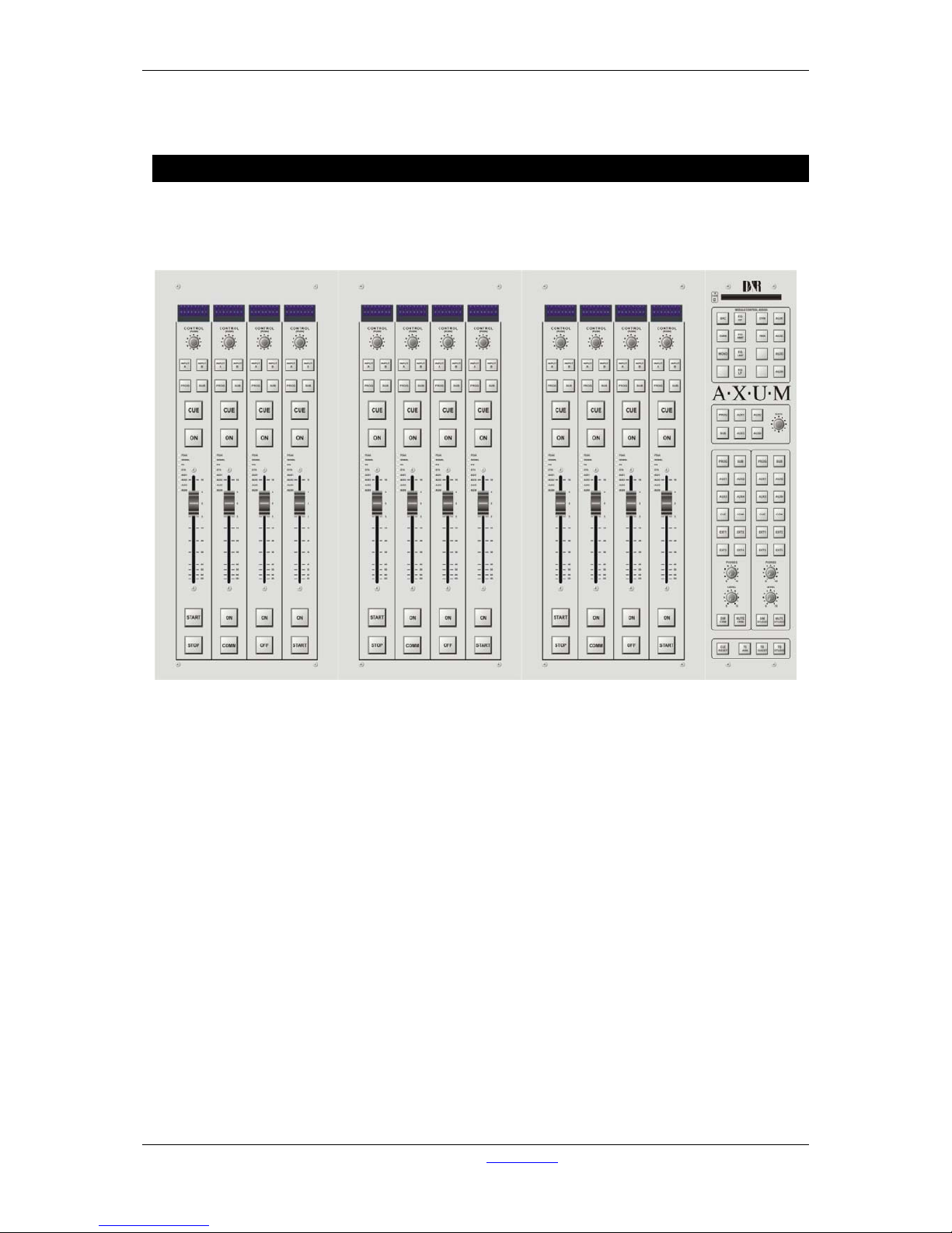
5 Control Surfaces
The engine will recognize the control surfaces of the AXUM digital audio system as ‘nodes with
objects’. Each object can connect to an engine (mixing console) function.
Below you see an example of a control surface and a short description of the node/object structure.
Figure 3: 12 fader control surface
This control surface holds 4 user interfaces nodes:
- 3x four fader panel node
- 1x monitor buss panel node
The ‘four fader panel node’ holds 84 objects:
- 4x Display upper line
- 4x Display lower line
- 4x Encoder
- 4x Encoder-push
- 32x LEDs
- 32x switches with LEDs (16 small, 16 large)
- 4x fader
The ‘monitor buss panel node’ holds 61 objects:
- 1 chip card
- 54 switches with LED’s
- 1 encoder
- 1 encoder push
- 4 potentiometers
Page 15
A·X·U·M User Manual Version 2.5 - 2011-01-28
AXUM from D&R - Phone: +31 294 418014 - E-Mail: info@d-r.nl - 15 -
6 AXUM Engine
The engine of the Axum drives all audio processing/routing and from the surfaces and remote
locations, it can be controlled using MambaNet. Therefore it is required that you setup the
engine/system with your settings before it will work according your requirements. Of course, we deliver
the system in a default configuration that will cover 90% of the functionality you wish.
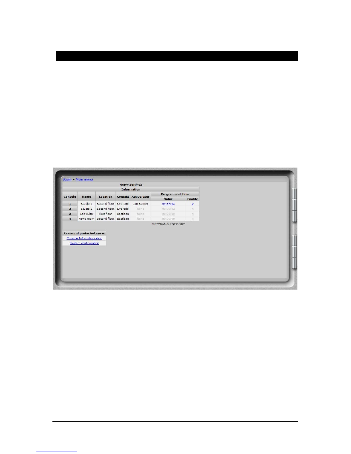
Setting up the engine (your mixing console) is done using your web browser.
Simply enter the IP address of the 19” rack in your browser and log-on to the configuration pages.
By default the IP Address is: http://192.168.0.200
(at the first startup you can use a network or cross wire with a static IP given to your network interface,
e.g. 192.168.0.10).
On the Axum website, you find all necessary options to configure your system as full functioning
mixing console(s), it’s the most to start with the Console 1-4 configuration. In this menu you may easy
step from top to bottom.
Figure 4: Axum web server
Page 16
A·X·U·M User Manual Version 2.5 - 2011-01-28
AXUM from D&R - Phone: +31 294 418014 - E-Mail: info@d-r.nl - 16 -
6.1 Console 1-4 configuration
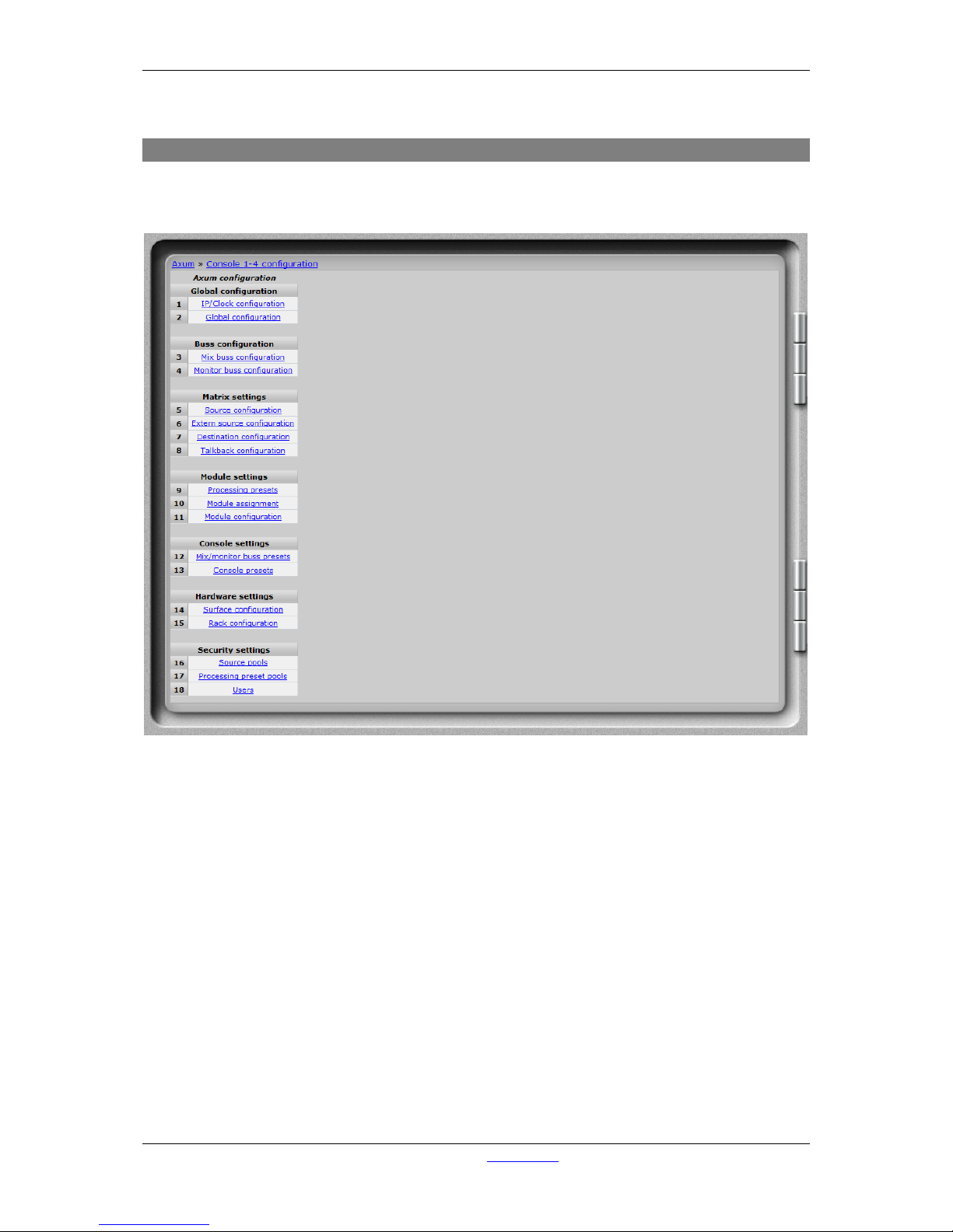
This pages shows all configuration possibilities to setup your console 1-4. Your system is
preconfigured but you may step through the menus for personal adjustments.
Figure 5: Console 1-4 configuration
Page 17
A·X·U·M User Manual Version 2.5 - 2011-01-28
AXUM from D&R - Phone: +31 294 418014 - E-Mail: info@d-r.nl - 17 -
6.1.1 IP/Clock configuration
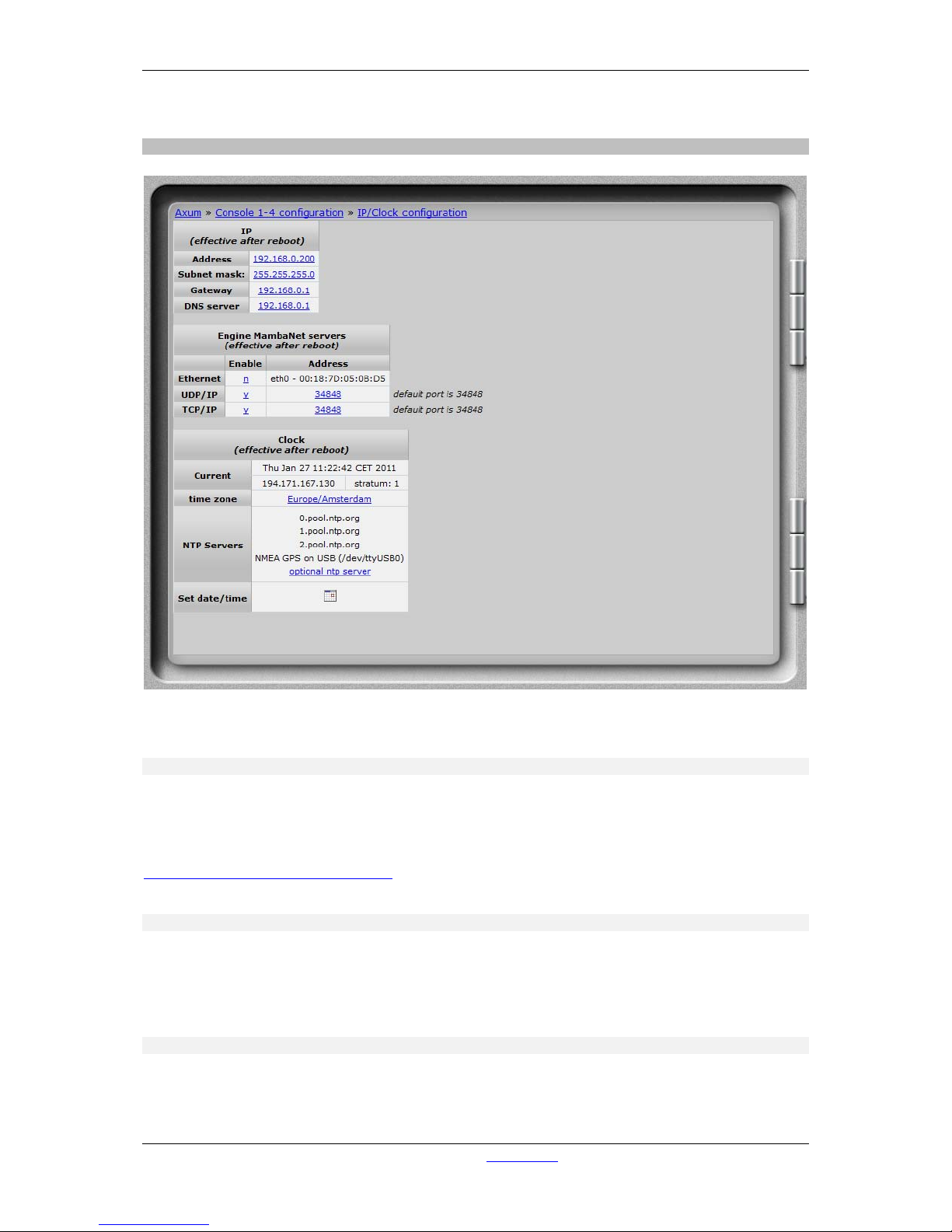
Figure 6: IP/Clock configuration
6.1.1.1 IP
Here you can setup the network settings to be compatible with the required settings in your situation
and you can set the time zone to where you are.
It’s possible to change the IP, subnet, gateway and DNS server address by clicking on the address.
For more information on IP addressing:
http://en.wikipedia.org/wiki/IP_address
WARNING: These setting become active after reboot.
6.1.1.2 Engine MambaNet servers
To enable and/or disable a specific server for Ethernet, UDP and/or TCP you can select here de y/n
field. Also the used UDP and TCP port can be changed to a non default value.
WARNING: These setting become active after reboot.
6.1.1.3 Clock
To change the time zone, click on the used time zone (in our example ‘Europe/Amsterdam’). You can
select the desired time zone in the list box.
Page 18

A·X·U·M User Manual Version 2.5 - 2011-01-28
AXUM from D&R - Phone: +31 294 418014 - E-Mail: info@d-r.nl - 18 -
The AXUM uses the NTP protocol for accurate clock synchronization. In the section ‘current’ you find
the IP address of the used ‘clock master’ and its ‘stratum’. For more information on NTP:
http://en.wikipedia.org/wiki/Network_Time_Protocol
When IP and DNS settings are setup correct, the AXUM will automatically synchronize to a pool of
time servers. The AXUM is also able to use a GPS receiver via USB for time synchronization. next,
the AXUM may function as a NTP server for the surfaces. There for, on the webserver of the control
surfaces you can configure the 'optional ntp server' and fill in the IP address of the ntp server (e.g.
192.168.0.200).
Set date/time may be used on system without any synchronization to set the correct time.
In the popup window it is possible to give to correct time and if you click on the ‘day’ it will become
direct changed/activated.
Remember that all other changes (NTP and IP settings) will become effective after reboot.
Page 19
A·X·U·M User Manual Version 2.5 - 2011-01-28
AXUM from D&R - Phone: +31 294 418014 - E-Mail: info@d-r.nl - 19 -
6.1.2 Global configuration
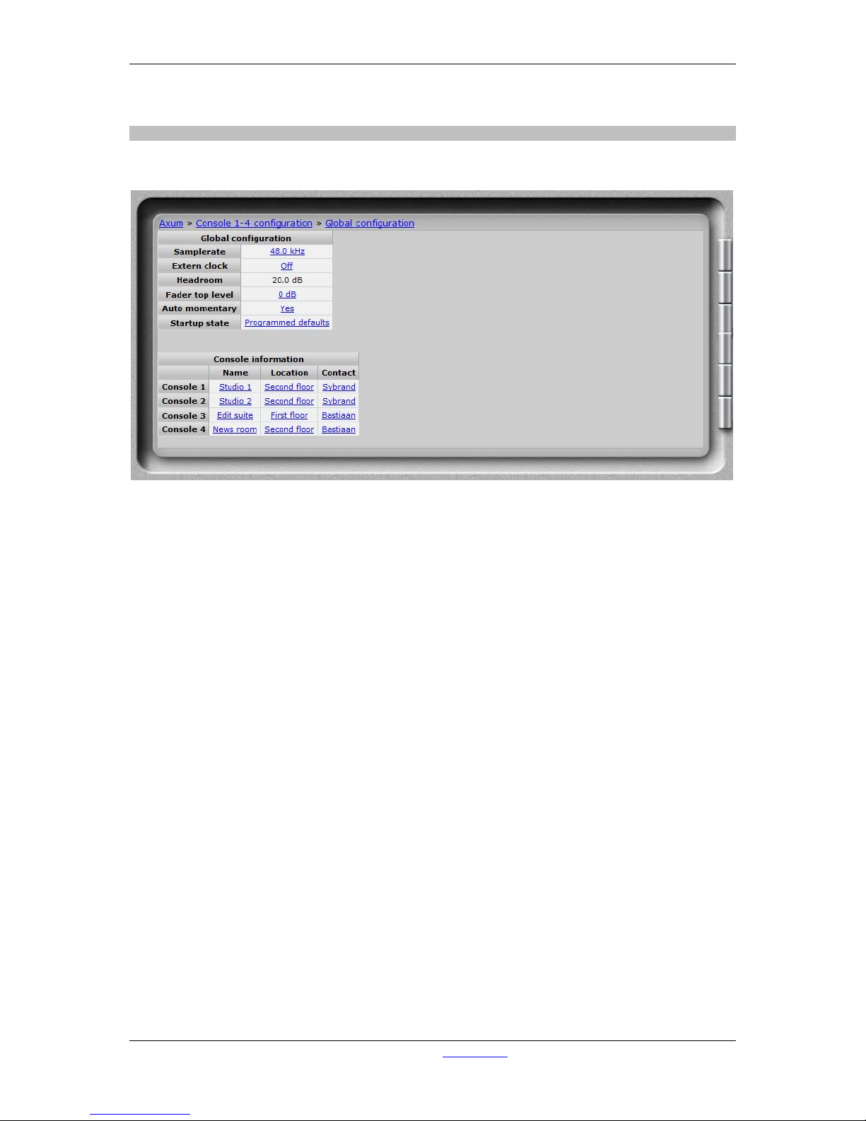
Some overall system settings can be filled in on this webpage.
Figure 7: Global configuration
• Sample rate
You can select a sample rate of 32 kHz, 44.1 kHz en 48kHz. According to this setting, the
filters are setup so you have to make sure to select the sample rate you work with. Also when
using an external clock.
• Extern(al) clock
If you want to use the external clock (Frame clock in) you can turn it on here.
• Headroom
The internal headroom is fixed at 20 dB, to adjust the headroom on a local input/output you
can give an offset level to the sources/destinations or at the rack configuration.
• Fader top level
You can make the fader work with or without 10 dB fader reserve. In the last situation the
faders will be 0 dB (unity gain) when the fader is fully up (maximum position).
• Auto momentary
Most switch functions can work in a auto-momentary mode. W hen set to yes a knob will
function latching when pressed shor tly. But with a long press (>750 mS) the knob reacts like a
momentary switch (function active while pressed).
• Startup state
Here you can select to use a known startup state which is the ‘programmed defaults’ or use a
‘backup of the last situation’.
Programmed defaults are the defaults as setup in the web-configuration. An backup of the
console is saved once a minute, which m eans you will return to (almost) the last situation.
• Console information
Here you can share some details to have an easier identification in a multi-studio environment.
Page 20
A·X·U·M User Manual Version 2.5 - 2011-01-28
AXUM from D&R - Phone: +31 294 418014 - E-Mail: info@d-r.nl - 20 -
6.1.3 Mix buss configuration
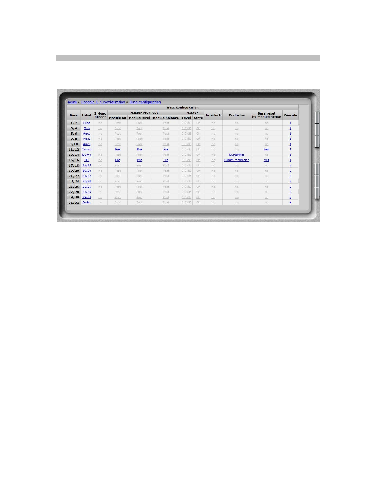
You have to setup the busses to create the names, console assignment and functionality of the
Busses. Here we see the setup for a single console buss setup:
Figure 8: Buss configuration
• Label
The name given to this buss.
• 2 Mono busses
It is possible to make 2 mono busses from one stereo buss. All buss-sends, to this buss, on
the module’s will now include stereo to mono summing.
• Master pre/post
You can choose the buss to be pre or post ON, level (comparable with pre/post fader) and
balance (could be your pan-pot).
• Master level/state
This setting is used as programmed startup level, so the buss masters are in a known state.
• Interlock
If you make a buss interlock, only 1 module can be assigned at the same time.
• Exclusive
When routing to an Dump/Rec exclusive buss is made, the routing to all other busses on that
module will be disabled. This is useful for a so called ‘dump buss’.
The selections Comm technician and Comm producer are used if you want to make a
communication buss. Such buss makes it possible to let presenters talk with hybrid or to talk
with an technician/producer.
• Buss reset
This setting can be used to create a CUE/PFL buss with auto-reset (CUE Reset).
If you have multiple studios and CUE/PFL busses you may assign reset to multiple busses.
• Console
You can select to which console a buss belongs.
Page 21
A·X·U·M User Manual Version 2.5 - 2011-01-28
AXUM from D&R - Phone: +31 294 418014 - E-Mail: info@d-r.nl - 21 -
6.1.4 Monitor buss configuration
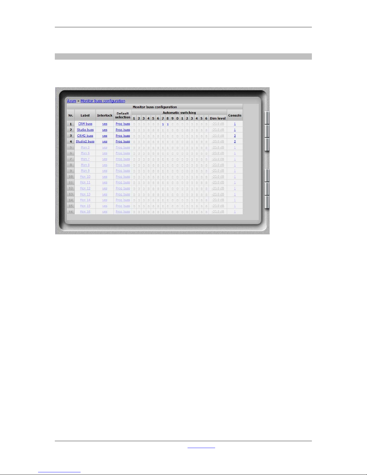
Per DSP card, you have 4 stereo monitor busses that can be used. They need a name, console
assignment and configuration so they can work properly:
Figure 9: Monitor buss configuration
• Label
Here you give a name to this monitor buss
• Interlock
Yes means only one source is active at the same time, on this monitor buss.
• Default selection
If the last selected source is turned off it will always go to the default selection.
This selection is also your startup default.
• Automatic switching.
You can tell the Engine that a monitor buss switches automatically when the ‘source buss’ is
activated. Also known as ‘PFL to CRM’. If you have two separate studios’ you can have
multiple automatically switched busses (e.g. PFL 1 and PFL 2).
When to mix buss is an exclusive buss, the monitor buss will also switch ‘exclusive’; normally
automatic switching will be summing with the set up ‘Dim level’.
• Dim level
When you have set the monitor buss to switch automatically, the source signal is dimmed by
the filled in level and the buss that is switched on to the Monitor buss is at unity gain (0 dB).
• Console
You can select to which console a monitor buss belongs.
Page 22
A·X·U·M User Manual Version 2.5 - 2011-01-28
AXUM from D&R - Phone: +31 294 418014 - E-Mail: info@d-r.nl - 22 -
6.1.5 Source configuration
The 19” rack unit can accept various I/O cards. These inserted I/O cards can accept audio in various
formats. This is because the audio connected to the I/O cards can have different channel relat ions
(mono, stereo). To create a user readable label you have to configure sources.
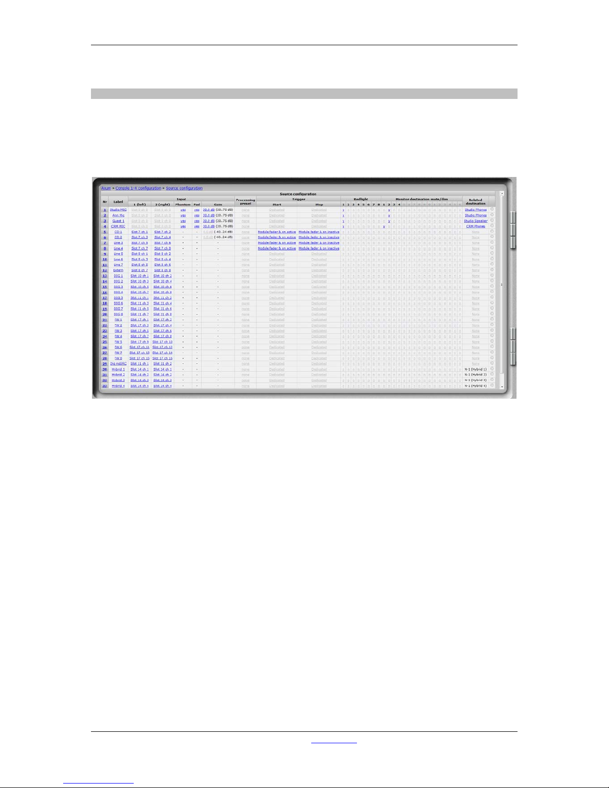
Such a source is the entity you can select to be the input of your module in the mixing console.
See below for a simple source list example:
Figure 10: Source configurati o n
• Nr
Here you can reposition the destination to make the list in a convenient order.
• Label
Name of the source you are creating.
• Input 1/2
Here you select the physical slot and input of the card you want to assign to this source.
For mono sources you selected the same input for left and right.
• Phantom
The phantom power for this source is turned on/off at startup.
(this field is only available when the source-phantom function is also assigned to an object;
e.g. via rack configuration)
• Pad
The PAD for this source is turned on/off at startup.
(this field is only available when the source-pad function is also assigned to an object; e.g. via
rack configuration)
• Gain
The source gain for this source is at startup set to this level.
(this field is only available when the source-gain function is also assigned to an object; e.g. via
rack configuration)
Page 23

A·X·U·M User Manual Version 2.5 - 2011-01-28
AXUM from D&R - Phone: +31 294 418014 - E-Mail: info@d-r.nl - 23 -
• Processing preset
If this source is selected on a module, by the ‘source select’ function (not via module or
console preset), this processing preset is ‘set’ on the module.
• Trigger start
Here you can configure how the source start/stop change is triggered:
- Dedicated, the module fader and on are not triggering start/stop only the dedicated start/stop
controllers.
- Module fader on, the fader on will trigger the start as well.
- Module on, the on switch will trigger the start as well.
- Module fader on & on, the fader must be open and on active then the start is triggered.
Dedicated start/stop objects will work in parallel with these ‘trigger start/stop’ modes
• Trigger stop
Here you can configure how the source start/stop change is triggered:
- Dedicated, the module fader and on are not triggering start/stop only the dedicated start/stop
controllers.
- Module fader off, the fader off will trigger the stop as well.
- Module off, the on switch will trigger the stop as well.
- Module fader off & off, the fader must be closed or on inactive then the stop is triggered.
Dedicated start/stop objects will work in parallel with these ‘trigger start/stop’ modes
• Red-light.
When this source becomes active on a module, the corresponding Red-light buss becomes
active.
• Monitor destination mute
When this source becomes active on a module, the corresponding monitor buss will be muted.
• Related destination
When you give a source a related destination it is possible to use TB functions on the module
and communication features from the GPIOs. For example you will make the relation
announcer microphone to announcer headphone.
• Delete
When you click on this column the source will be deleted (and also all references are deleted).
• Create a new source
By clicking on this link a popup will appear where you have to setup the physical inputs and
label for the new source.
Page 24
A·X·U·M User Manual Version 2.5 - 2011-01-28
AXUM from D&R - Phone: +31 294 418014 - E-Mail: info@d-r.nl - 24 -
6.1.6 Extern source configuration
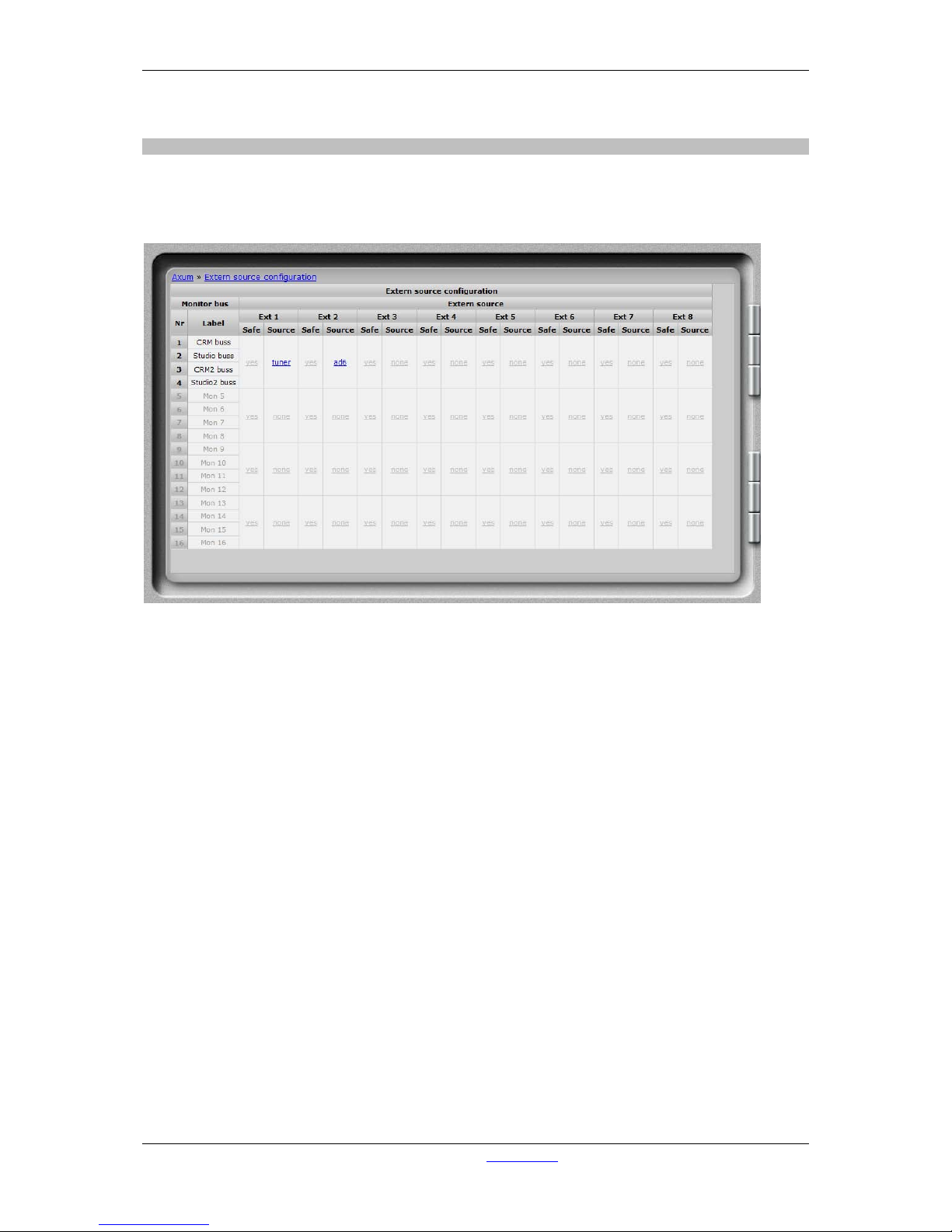
Each DSP card can handle four stereo monitor busses (with 4 DSP cards a max of 16 stereo monitor
busses is possible). For each DSP card you can configure 8 external stereo sources, beyond the 16
stereo mixing busses which are fixed available in the monitor section.
Figure 11: External source co n figuration
• Safe
Extern source can be configured to be ‘interlock safe’.
Normally only one buss or external input can be active on the monitor buss if configured to be
‘interlock’. But sometimes it is important your signal will not disappear if another CRM-source
is selected, in that case you can set the external source to be ‘safe’.
• Source
Here you can select which signal routes to this ‘external input’.
You can choose:
- Input sources (Mic, line, dig etc. etc.)
- Mix busses
- Monitor busses
- Insert outs (of modules)
- N-1 signals (for a single module)
Page 25
A·X·U·M User Manual Version 2.5 - 2011-01-28
AXUM from D&R - Phone: +31 294 418014 - E-Mail: info@d-r.nl - 25 -
6.1.7 Destination configuration
The 19” rack unit can accept various I/O cards. With these cards, you can send audio from the Axum
digital audio system to the audio format you require. Because the audio connected to the I/O cards
can have different channel relations (mono, stereo) a combination has to be made. A user readable
label has to be created to configure destinat ions. Such destination is the entity you can select to be
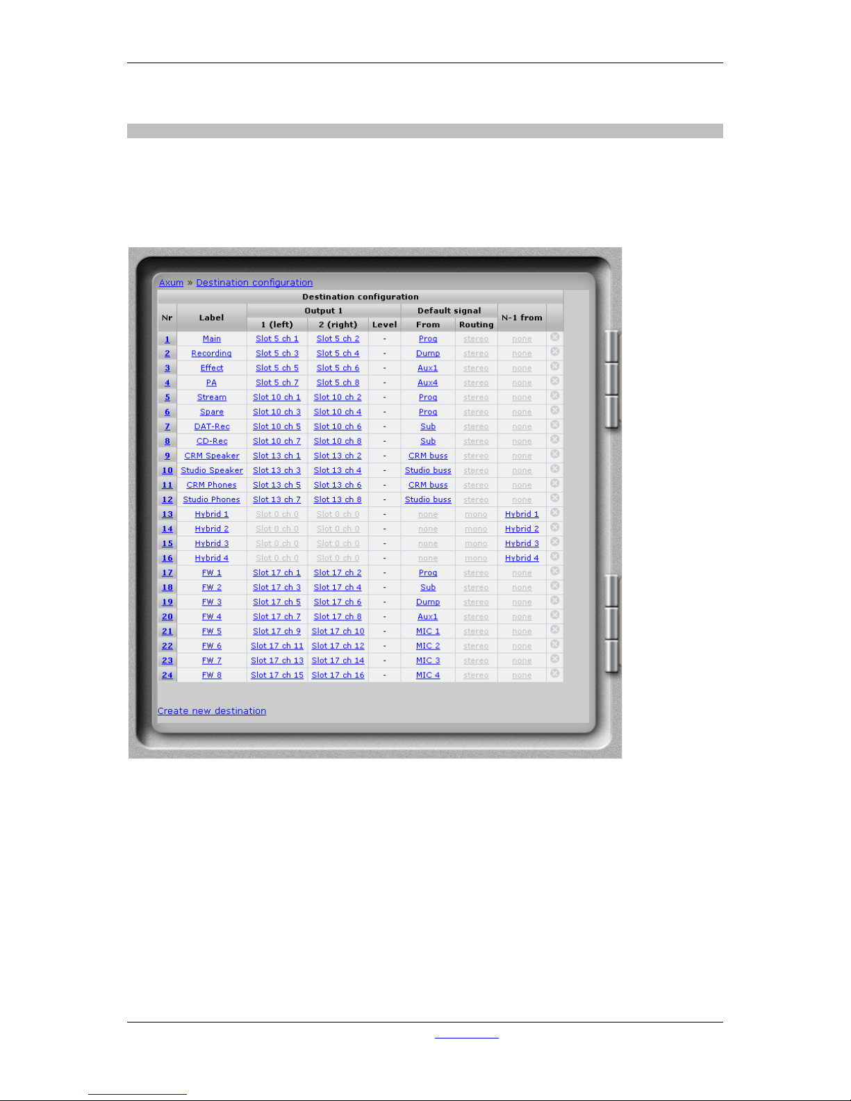
the output of a mixing buss of the mixing console. See an example destination list:
Figure 12: Destination configuration
• Nr
Here you can reposition the destination to make the list in a convenient order.
• Label
Name of the destination you are setting up.
• Output 1/2
Here you select the physical slot and output of the card you want to assign to this destination.
For a mono output you have to select only one of the left or right outputs to a physical slot/ch.
• Level
The destination level for this source is at startup set to this level; for example to adjust
headroom for a single output.
Page 26

A·X·U·M User Manual Version 2.5 - 2011-01-28
AXUM from D&R - Phone: +31 294 418014 - E-Mail: info@d-r.nl - 26 -
(this field is only available when the destination-level function is also assigned to an object;
e.g. via rack configuration)
• Default signal from
This destination/output will send audio from the default selected source (except if a N-1 is
active, then automatically the N-1 signal is selected).
You can choose:
- Input sources (Mic, line, dig etc. etc.)
- Mix busses
- Monitor busses
- Insert outs (of modules)
• Default signal routing
Here you can choose which signal feeds the physical outputs:
Stereo (if no mix minus source is assigned):
Output left and right received their corresponding signal
Left:
Output left and right both receive the left signal.
Right:
Output left and right both receive the right signal.
Mono (only if a mix minus source is assigned):
The mix minus signal is always a mono signal.
• N-1 from/mix minus source
When the selected source is assigned to a module, this destination automatically creates an
N-1 using the selected source. There is no limitation on the amount of N-1s, every module is
able to make its own N-1.
• Delete
When you click on this column the destination will be deleted (and also all references are
deleted).
• Create a new destination
By clicking on this link a popup will appear where you have to setup the physical outputs and
label for the new destination. When you select the same output for both channels, the system
will use it on the left output and set the right to none.
Page 27
A·X·U·M User Manual Version 2.5 - 2011-01-28
AXUM from D&R - Phone: +31 294 418014 - E-Mail: info@d-r.nl - 27 -
6.1.8 Talkback configuration
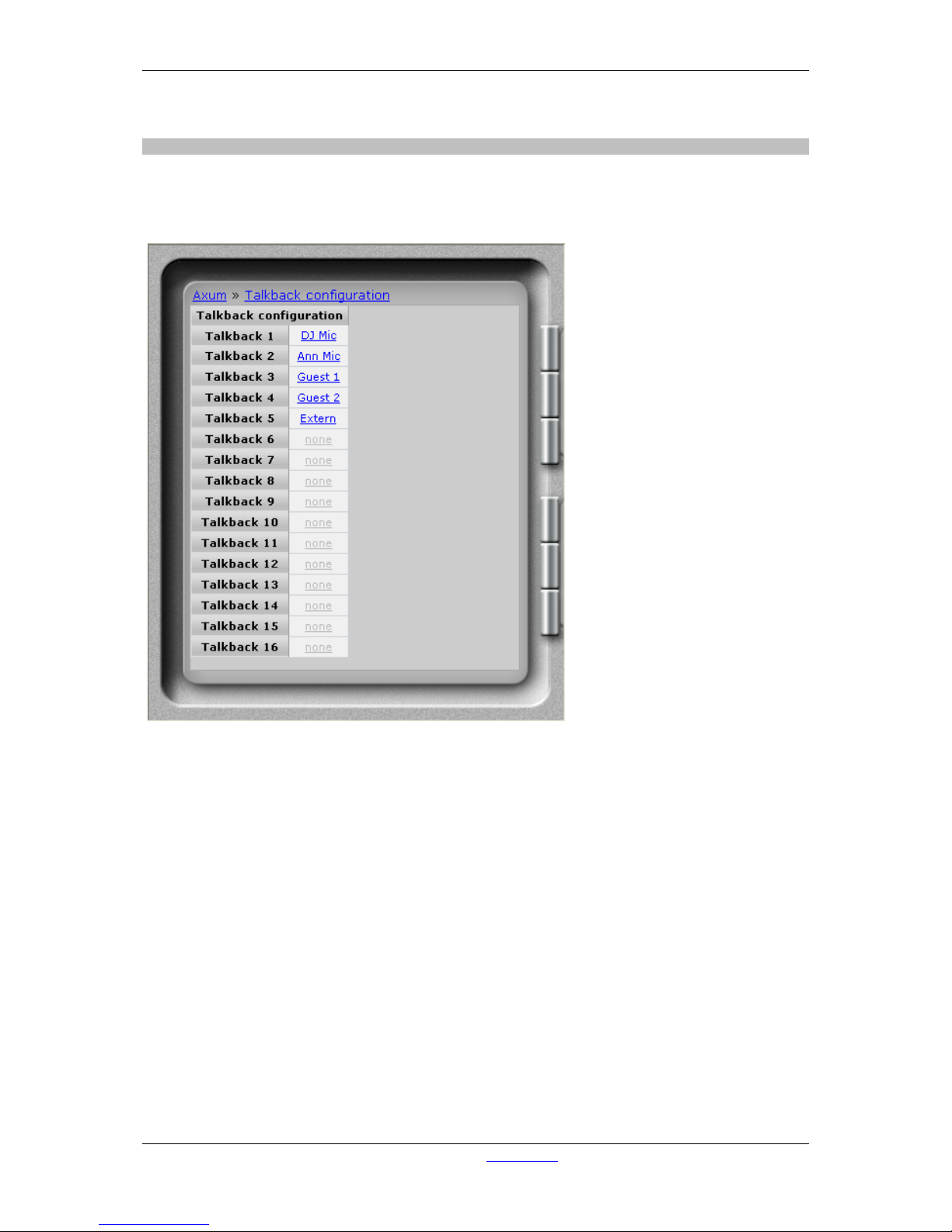
This page makes it possible to select the sources for the 16 talkback busses available in the AXUM.
A talkback buss may be summed/switched to any destination of the AXUM system, this will not require
any DSP resources.
Figure 13: Talkback configuration
• Source
Here you can select which signal routes to a talkback buss.
You can choose:
- Input sources (Mic, line, dig etc. etc.)
- Mix busses
- Monitor busses
- Insert outs (of modules)
- N-1 signals (for a single module)
Page 28
A·X·U·M User Manual Version 2.5 - 2011-01-28
AXUM from D&R - Phone: +31 294 418014 - E-Mail: info@d-r.nl - 28 -
6.1.9 Processing presets
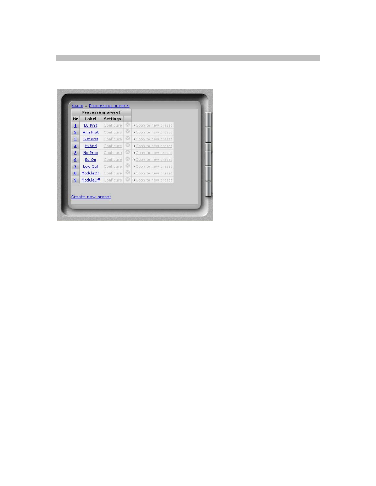
It is possible to set the module processing when a source is selected (via ‘source select’ or a module
preset) , the information for this functionality is stored in the processing presets.
Figure 14: Processing presets
• Nr
Here you can reposition the preset to make the list in a convenient order.
• Label
Name of the preset.
• Settings.
Shows a new page where you can configure the preset.
• Delete
When you click on this column the preset will be deleted (and also all references are deleted).
• Copy to new preset
This function can be used to get the current settings copied in a new preset.
A popup will appear where you have to setup the label for the new preset.
• Create new preset
By clicking on this link a popup will appear where you have to setup the label for the new
preset.
Page 29
A·X·U·M User Manual Version 2.5 - 2011-01-28
AXUM from D&R - Phone: +31 294 418014 - E-Mail: info@d-r.nl - 29 -
6.1.9.1 Settings
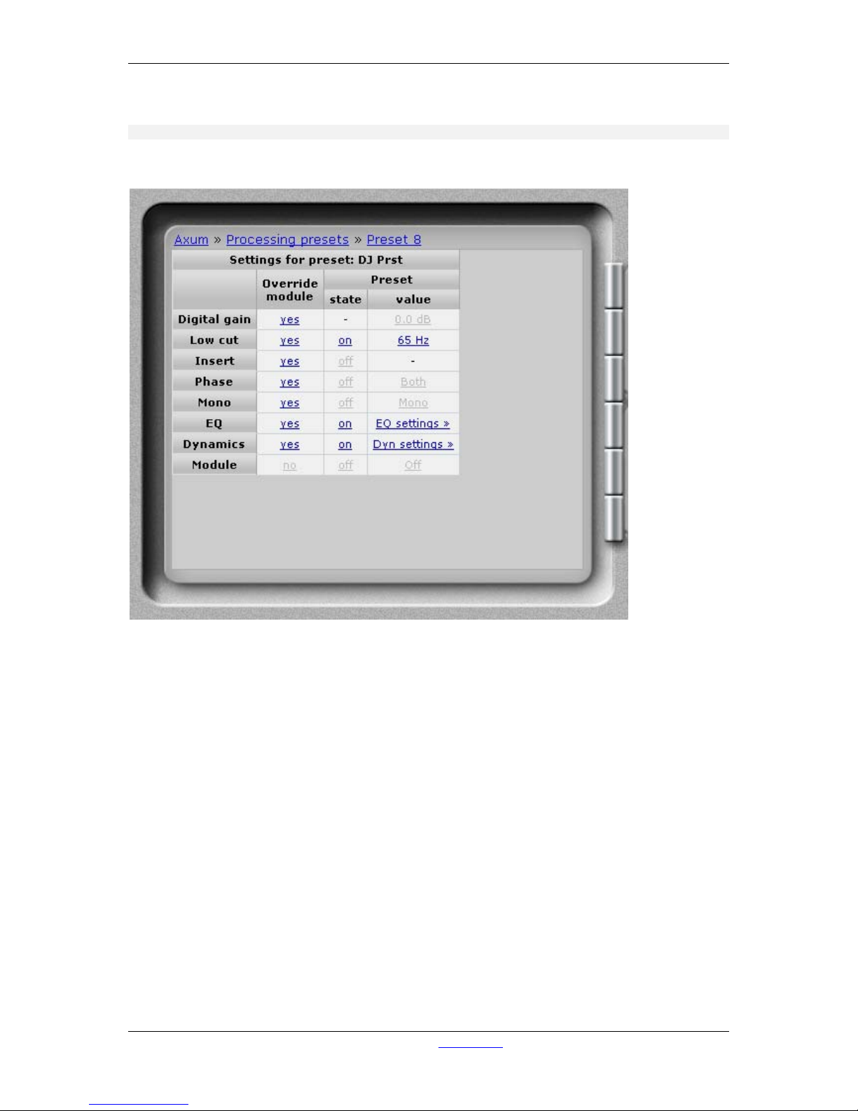
All processing parameters can be configured in the processing preset settings webpage
Figure 15: Processing preset settings
• Override module
If set to no, the module setting will not be affected by this preset.
If set to yes, this preset will change the settings of the module for the corresponding
processing section (Digital gain, Low cut etc. etc.)
• State
if the override is turned to yes, you can set the processing section to ‘on’ or ‘off’.
for example:
- Microphones will often have the state EQ on
- CD players will often have the state EQ off
• Value
if the override is turned to yes, this value is set for the corresponding processing section.
Page 30
A·X·U·M User Manual Version 2.5 - 2011-01-28
AXUM from D&R - Phone: +31 294 418014 - E-Mail: info@d-r.nl - 30 -
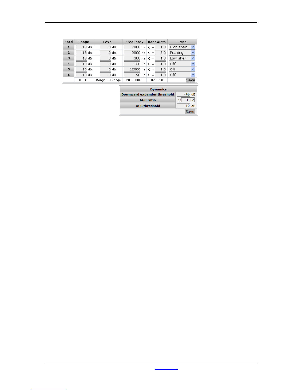
For EQ and dynamics, a popup window is shown. Here you can set multiple values.
Figure 16: Processing preset EQ/Dynamics settings
EQ Range
Maximal adjustment you may generate with this band.
EQ Level
Level of the band that this preset will set.
The value must be within the EQ Range
EQ Frequency
Frequency of the band that this preset will set.
The frequency range is 20-20000 Hz.
EQ Bandwidth
Bandwidth of the band that this preset will set.
The bandwidth range is 0.1 – 10
EQ type
Type of the band that this preset will set.
You can choose:
- Off
- High pass filter (6 dB/Oct)
- Low shelf
- Peaking (is the normal EQ curve)
- High shelf
- Low pass filter
- Band pass filter
- notch filter
Downward expander threshold
Threshold of the downward expander (to reduce ambient sound) that this preset will set.
The threshold range is -50 dB till 0 dB.
AGC ratio
The ratio for this automatic gain control is given in 1:1 to 1:25
AGC threshold
Threshold of the AGC, above the threshold the AGC tries to hold the signal 0 dB.
the threshold range is -30 till 0 dB.
(Be aware with a low threshold, you may generate a lot of gain)
Page 31
A·X·U·M User Manual Version 2.5 - 2011-01-28
AXUM from D&R - Phone: +31 294 418014 - E-Mail: info@d-r.nl - 31 -
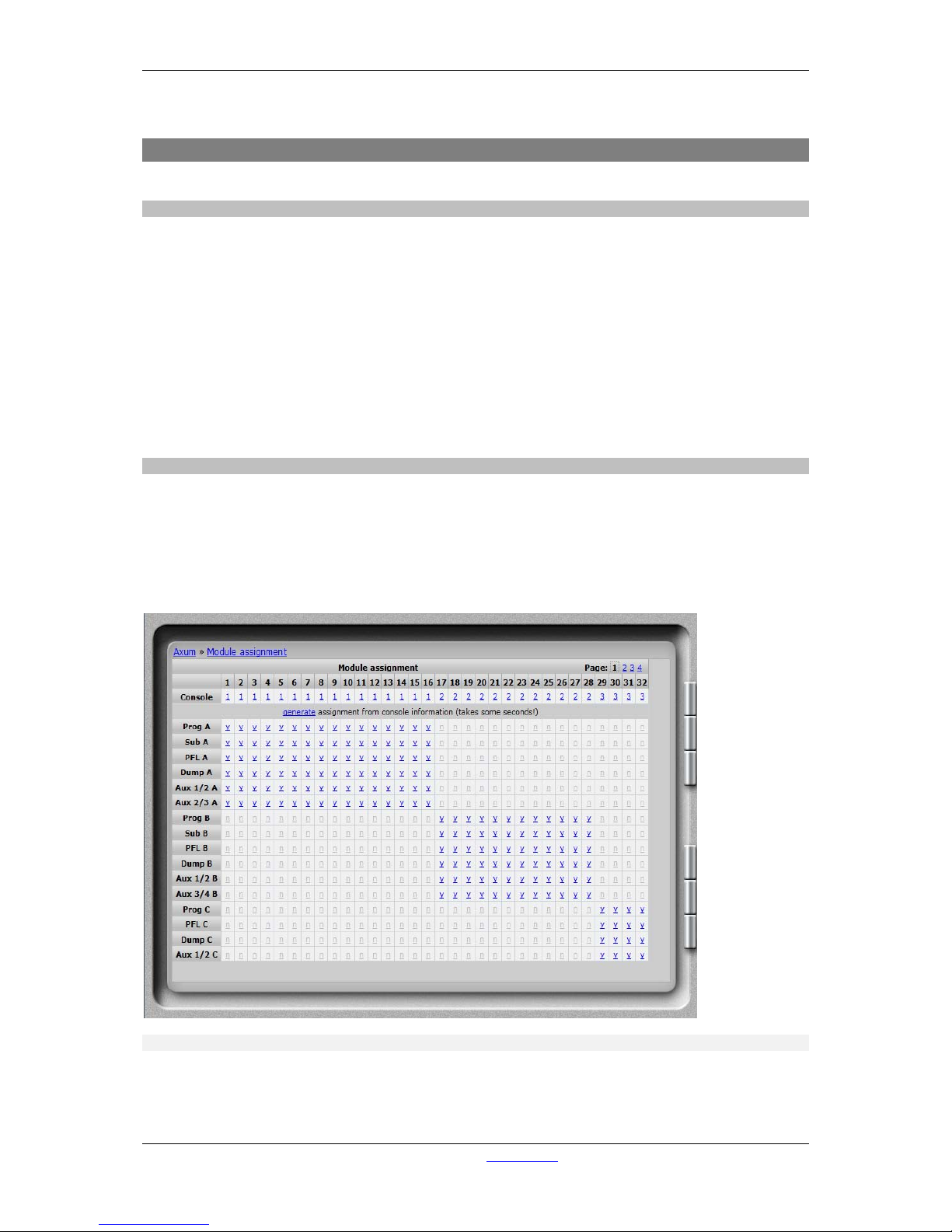
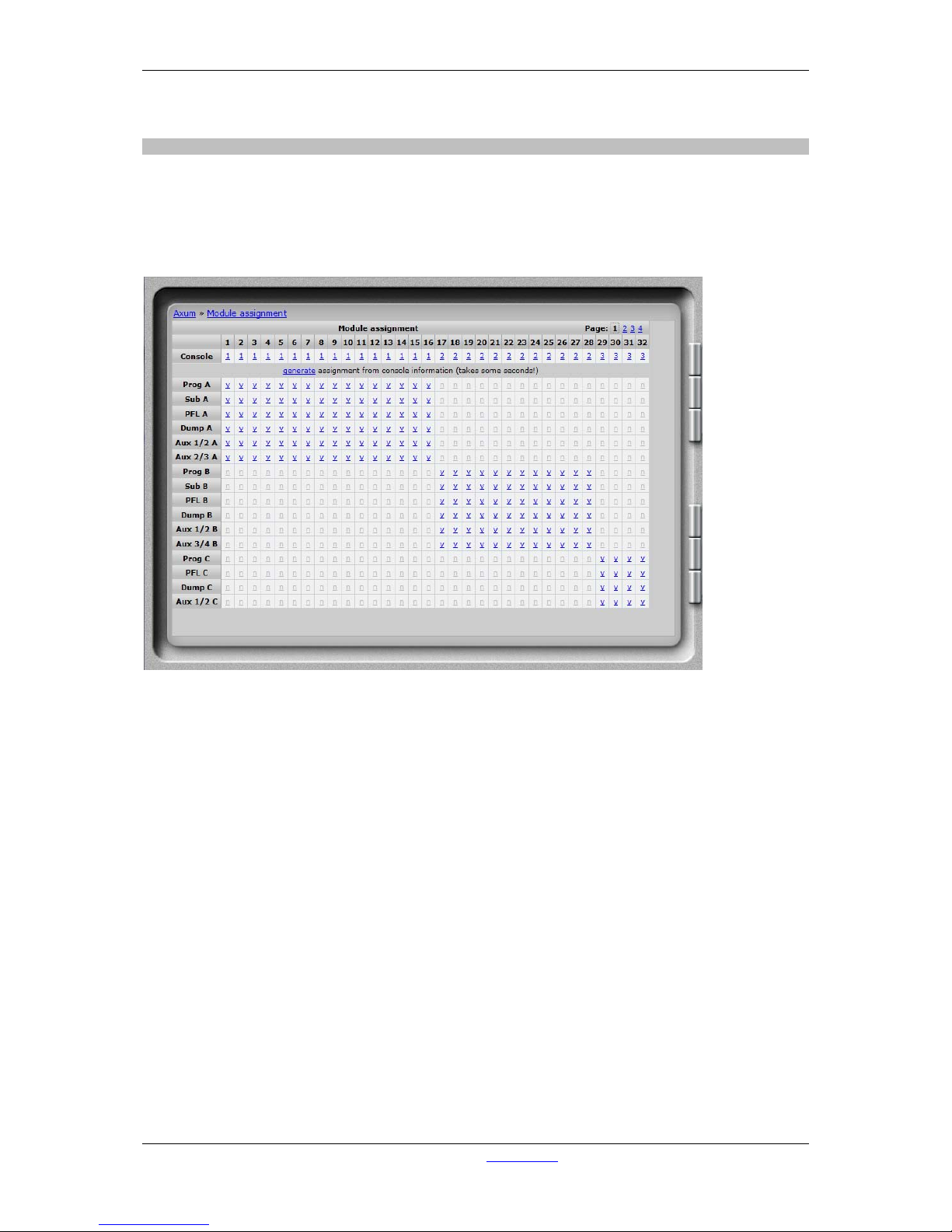
6.1.10 Module assignment
Modules can be assigned to one of the 4 consoles, after this and a correct assignment of the busses
(in buss configuration) to the consoles you may click ‘generate’ to make a correct assignment
configuration.
Afterwards you can override the generate assignments by clicking the ‘y’/’n’ fields. For example you
can create a buss that is available to all consoles.
Figure 17: Module assignment
Page 32
A·X·U·M User Manual Version 2.5 - 2011-01-28
AXUM from D&R - Phone: +31 294 418014 - E-Mail: info@d-r.nl - 32 -
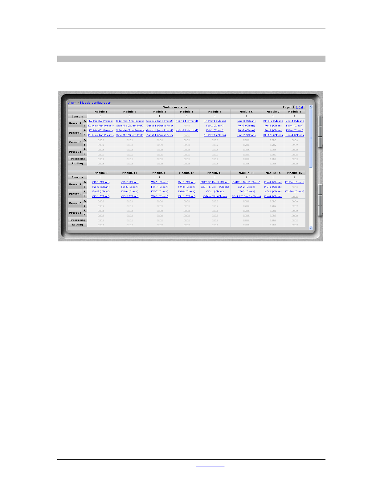
6.1.11 Module configuration
The module configuration makes it possible to give modules a default setting (after powering on) and
you can also configure module presets 1A/1B, 2A/2B, 3A/3B, 4A/4B.
Figure 18: Input module configuration
• Console
Shows to which console the module is assigned.
• Preset 1A/1B, 2A/2B, 3A/3B, 4A/4B
Shows the source and processing preset selected for corresponding module preset. If the ‘#’
symbol appears there is an active routing preset.
(click on the link to go to the configuration page for the module)
• Processing
Here you can see if there is any processing done.
(click on the link to go to the configuration page for the module)
• Routing
(click on the link to go to the configuration page for the module)
Page 33
A·X·U·M User Manual Version 2.5 - 2011-01-28
AXUM from D&R - Phone: +31 294 418014 - E-Mail: info@d-r.nl - 33 -
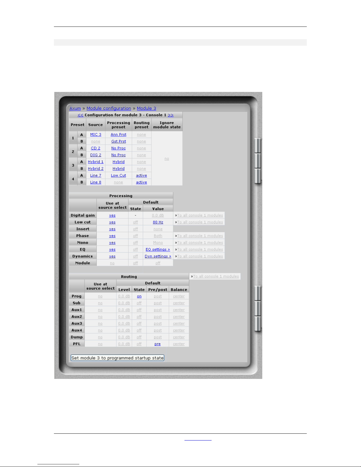
6.1.11.1 Module configuration page
On this page you can setup the default module configuration, used at startup if programmed default is
selected in global configuration. If you have made your settings and you would like to copy them to all
modules in this console (for example if you want to use the same EQ center frequencies) you can
simply hit ‘To all console x modules’ after you made and checked the settings on the current module.
Figure 19: Module configuration page
Page 34
A·X·U·M User Manual Version 2.5 - 2011-01-28
AXUM from D&R - Phone: +31 294 418014 - E-Mail: info@d-r.nl - 34 -
6.1.11.2 Module preset 1A/1B, 2A/2B, 3A/3B, 4A/4B
Here you select the source, processing preset and routing preset that is used when module preset
1A/1B, 2A/2B, 3A/3B, 4A/4B is selected. After a click on ‘routing’ a popup appears with the routing
possibilities (this depends on the console assignment).
• Source
If you click here a popup appears with a list of all available sources. Select the source you
want to use in this module preset.
• Processing
If you click here a popup appears with a list of all available processing presets. Select the
source you want to use in this module preset.
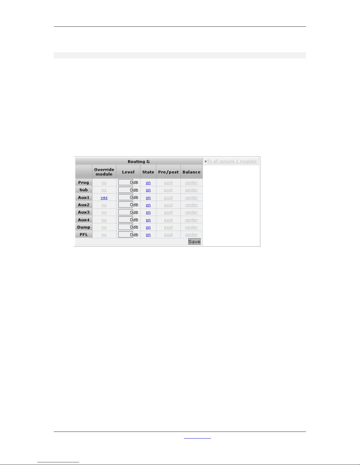
• Routing Preset
Figure 20: Module routing preset
Override module
If set to no, the module setting will not be affected by this preset. If set to yes, this preset will
change the settings of the module for the corresponding buss.
Level
If the override is turned to yes, this will set the send level to the buss for this module when
current preset is selected.
State
If the override is turned to yes, this will set the buss state to ‘on’ or ‘off’ for this module when
this module preset is select.
Pre/Post
If the override is turned to yes, this will set the buss pre or post for this module when this
module preset is select.
Balance
If the override is turned to yes, this will set the buss balance for this module when this module
preset is select.
To all console 1-4 module
With this link you can copy the current settings to the same routing preset (1A/1B, 2A/2B,
3A/3B, 4A/4B) at all modules of the console where this module is assigned to.
Page 35

A·X·U·M User Manual Version 2.5 - 2011-01-28
AXUM from D&R - Phone: +31 294 418014 - E-Mail: info@d-r.nl - 35 -
• Ignore module state
When presets are recalled, it checks the module state to prevent recalling ‘onair’ signals. The
preset will wait till the module is switched off air.
If the ignore module state function is switched to yes, the presets will not check the module
state and forces the recall to be done always!
6.1.11.3 Processing
These are the programmed processing defaults for the modules. Depending on the startup settings
these processing defaults will be used at startup (programmed defaults in global configuration).
The field ‘Use at source select’ determines if the default module processing in the source configuration
is used when a source is assigned via the module source select functionality and no processing preset
is assigned in the ‘source configuration’.
The following state/value processing sections are available:
• Digital Gain level
You can enter a default gain level for each module and determine if the default state must be
on or off.
• Low cut frequency
You can enter a default frequency of the low cut filter and determine if the default state must
be on or off.
• Insert
You may select a source to be your insert return for this module and determine if the default
state must be on or off.
• Phase
Set the phase default settings (Left only, right only or both channels are phase reversed). It is
also possible to determine if the default state must be on or off.
• Mono
Give the mono settings default values (left, right or mono-sum of left and right). It is also
possible to determine if the default state must be on or off.
• EQ
By clicking on EQ you can set the default equalizer settings it will appear in a popup window.
The state may be used to set the EQ default on or off.
• Dynamics
This setting is used as default, the popup shows the parameters to setup. The state may be
used to set the dynamics to be default on or off.
• Module
Here you may set the default module level at startup, the state will be the default module
on/off state.
The ‘Ignore module state’ function makes it possible to load a processing preset even if the module is
active (fader open and module on). This may be necessary if you use presets on a ‘virtual console’.
Page 36

A·X·U·M User Manual Version 2.5 - 2011-01-28
AXUM from D&R - Phone: +31 294 418014 - E-Mail: info@d-r.nl - 36 -
6.1.11.4 Routing
The field ‘Use at source select’ determines if the default module routing is used when a source is
assigned via the module source select functionality .
The following routing sections are available:
• Buss level
You may predefine the send level of a module to the busses (e.g. Aux send).
• Buss status
You have to setup the startup status for the busses. With this setting you set the buss routing
(e.g. Program on/off or CUE on/off).
• Buss Pre/Post
It’s possible to have pre/post selection per module, the startup setting can be configured here.
• Balance
You can select the balance of the buss sent.
6.1.11.5 Set module 1 to programmed startup state
When you click this button the module will directly load the setup module defaults.
Page 37
A·X·U·M User Manual Version 2.5 - 2011-01-28
AXUM from D&R - Phone: +31 294 418014 - E-Mail: info@d-r.nl - 37 -
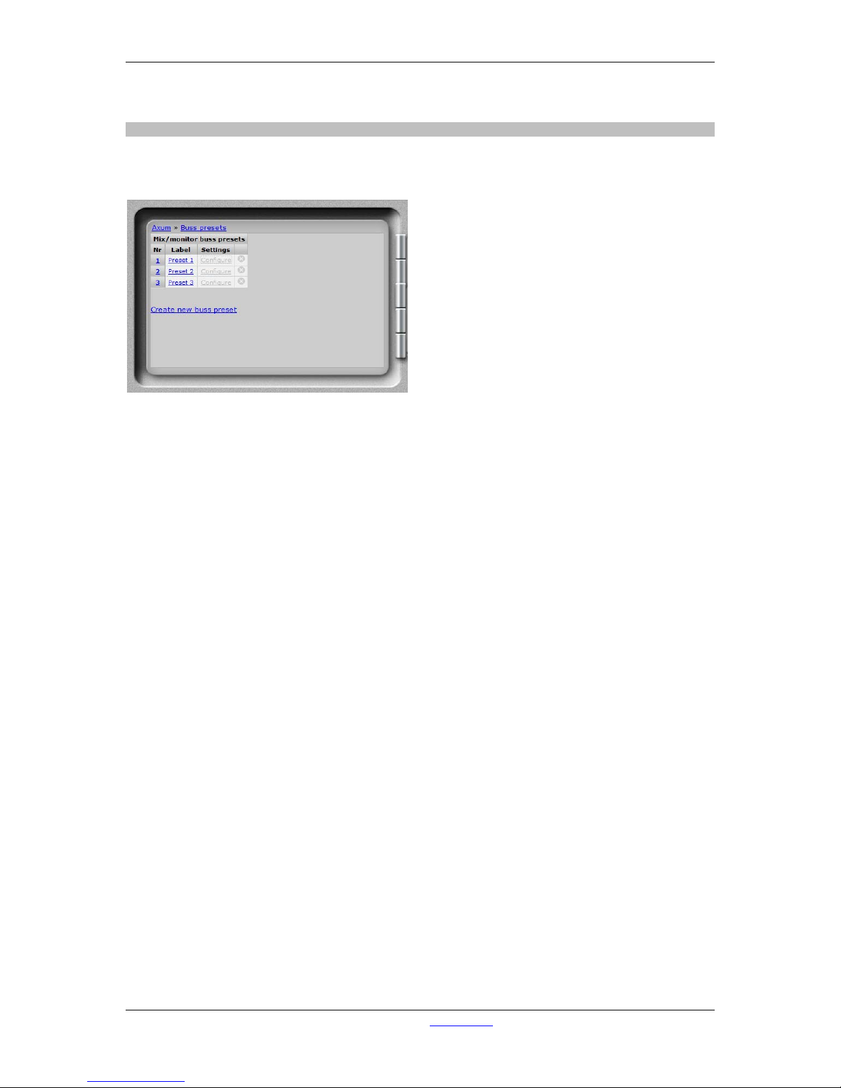
6.1.12 Mix/monitor buss presets
It is possible to make mix/monitor buss presets to make sure the correct buss master states and levels
are set for different programs. Also you can make sure the required monitor buss selection is made.
Figure 21: Mix/monitor buss presets
• Nr
Here you can reposition the preset to make the list in a convenient order.
• Label
Name of the preset.
• Settings.
Shows a new page where you can configure the preset.
• Delete
When you click on this column the preset will be deleted (and also all references are deleted).
• Create new buss preset
By clicking on this link a popup will appear where you have to setup the label for the new
preset.
Page 38
A·X·U·M User Manual Version 2.5 - 2011-01-28
AXUM from D&R - Phone: +31 294 418014 - E-Mail: info@d-r.nl - 38 -
6.1.12.1 Settings
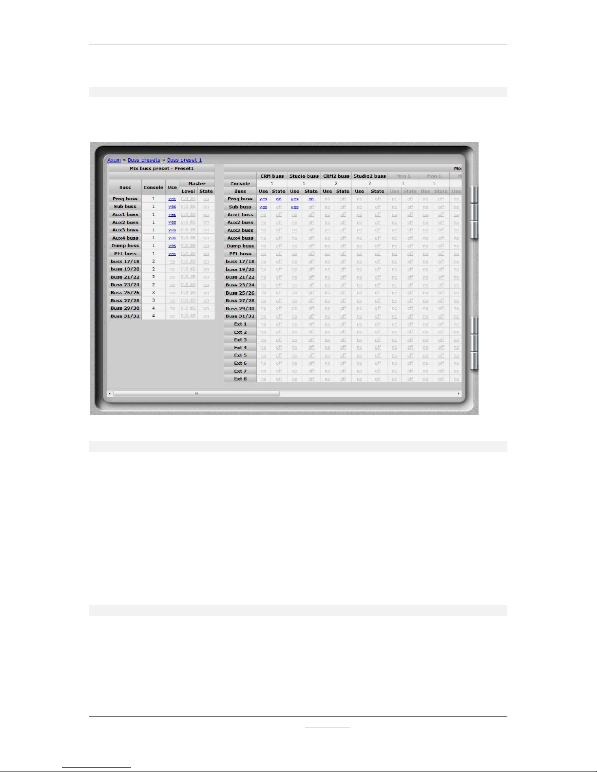
On this page you can set the required levels and state for all busses and monitor busses which are
used in the mix/monitor buss preset.
Figure 22: Mix/monitor buss preset settings
6.1.12.2 Mix buss settings
• Console
Displays the console where this mix buss is assigned to.
• Use
When set to ‘yes’ the settings for this mix buss overrides the current mix settings if the preset
is loaded.
• Master level
Here you can give the preset master level of the corresponding mix buss.
• Master state
Here you can give the preset master state of the corresponding mix buss.
6.1.12.3 Monitor buss settings
• Console
Displays the console where this monitor buss is assigned to.
• Use
When set to ‘yes’ the settings for this monitor buss overrides the current monitor settings if the
preset is loaded.
Page 39

A·X·U·M User Manual Version 2.5 - 2011-01-28
AXUM from D&R - Phone: +31 294 418014 - E-Mail: info@d-r.nl - 39 -
• State
This must be set to ‘on’ to force this monitor-buss routing to be active. When it is set to ‘off’ the
monitor-buss routing will be forced to go ‘off’.
Page 40
A·X·U·M User Manual Version 2.5 - 2011-01-28
AXUM from D&R - Phone: +31 294 418014 - E-Mail: info@d-r.nl - 40 -
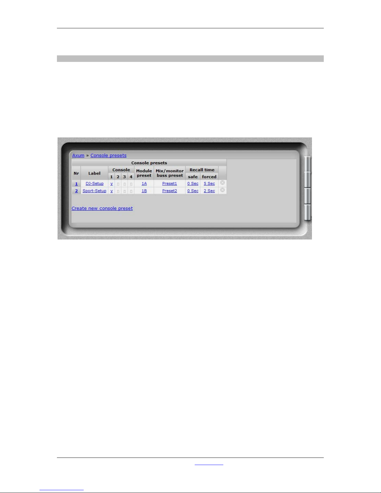
6.1.13 Console presets
To recall a complete console you use the console presets, what exactly is recalled is depending on the
underlying configuration of:
- Source configuration
- Processing presets
- Module configuration
- Mix/monitor buss presets
When a console preset is recalled it will set all modules to the module preset ‘A’-‘H’ as configured.
Secondly it will load the Mix/monitor pres et as given in the conso le pres et.
Figure 23: Console presets
• Nr
Here you can reposition the preset to make the list in a convenient order.
• Label
Name of the preset.
• Console
Select to which console or consoles this preset is active.
• Module preset
Here you can select to use module preset 1A/1B, 2A/2B, 3A/3B, 4A/4B.
• Mix/monitor buss preset
Here you can select one of the mix/monitor buss presets to use in this console preset.
• Recall time
A console preset can be recalled onair safe, so active channels are not recalled. Default you
have to press the preset button for 1 second before an ‘safe’ recall is done. After pressing 3
seconds the active channels are recalled as well (forced).
You can setup the delay time for the safe and forced console presets, when you give 0
seconds the recall will be done ‘direct’ when the button is pressed.
• Delete
When you click on this column the preset will be deleted (and also all references are deleted).
• Create new console preset
By clicking on this link a popup will appear where you have to setup the label for the new
preset.
Page 41
A·X·U·M User Manual Version 2.5 - 2011-01-28
AXUM from D&R - Phone: +31 294 418014 - E-Mail: info@d-r.nl - 41 -
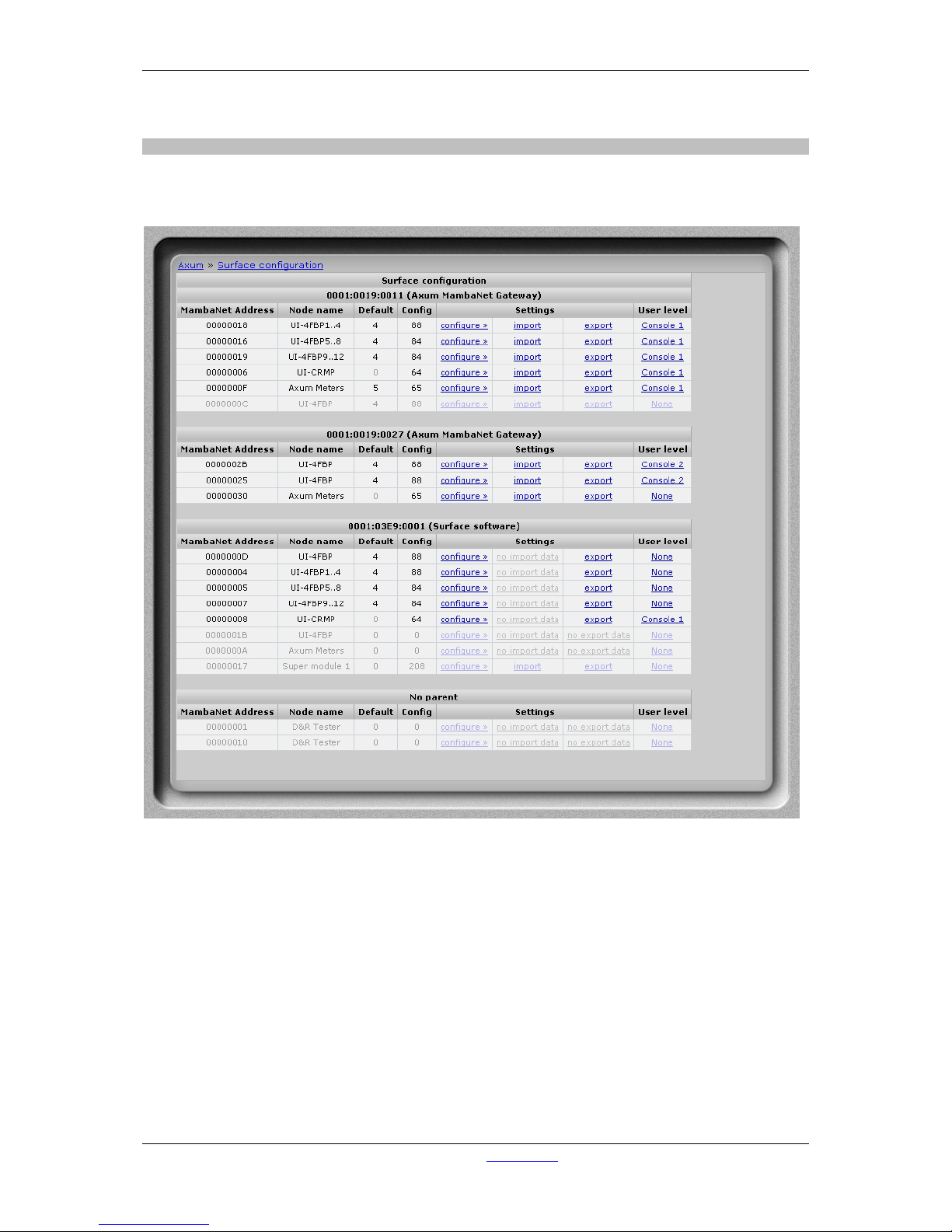
6.1.14 Surface configuration
You can see an overview of the boards in the surface(s) on this page. These are grouped together,
like their physical layout.
Figure 24: Surface configuration
• MambaNet Address
Show information on the internal used MambaNet addresses
• Node name
Logical name of the node
• Default
Number of objects that have a default value set.
• Config
Number of objects that are configured to an engine function.
• Import/Export
Once you have configured the defaults and used engine functions you can export and import
these settings. With export the current configuration is stored in the database, where you have
to give a logical name (e.g. Module 5-8). With import you can restore a configuration to the
Page 42
A·X·U·M User Manual Version 2.5 - 2011-01-28
AXUM from D&R - Phone: +31 294 418014 - E-Mail: info@d-r.nl - 42 -
same or a different node (of the same type). When you import Module 5-8 with an offset of -4
the configuration will be as you expect Module 1-4.
• User level
Here you can define to which console the module belongs in terms of user level. The user
level depends on the user logged on to the AXUM system. If ‘None’ is selected this node will
always have full access.
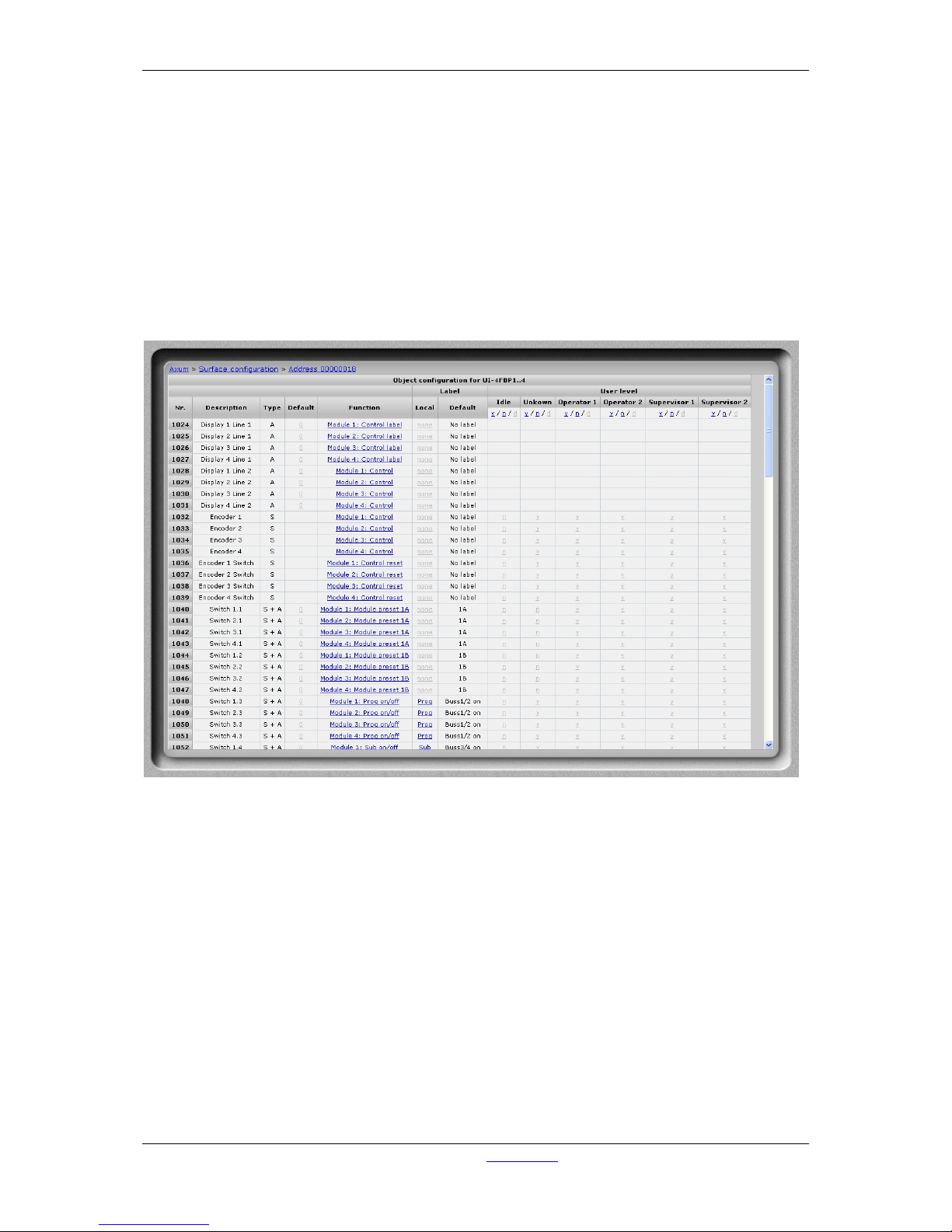
• Configure
When you follow the link configure, you are able to setup the functionality for the different
objects on the node. The sensor and actuator data types determine which function is able to
connect to the object. For a complete list of the functions, you can go to chapter 20 Appendix
C – Engine functions.
Figure 25: Node object configuration (to Axum functions)
• Default
The gray value is the startup default, this may be changed by assigning a custom value.
When you submit an empty box the object returns to the startup default value.
• Function
Here you may select which engine function is connected to the object
• Label
Here you may change the label, which is a shortcut for the selected function, if none is given
the default function label will be used (the label will appear in the remote configuration
software).
• User level
Per user level you can overwrite the default level per function. If y is selected the function will
be available in the selected user level. If n is selected the function won´t be available. if the y/n
value is shown light gray, the function default user level is used.
In the column headers you may toggle the user level for all objects in the node.
Page 43
A·X·U·M User Manual Version 2.5 - 2011-01-28
AXUM from D&R - Phone: +31 294 418014 - E-Mail: info@d-r.nl - 43 -
6.1.15 Rack configuration
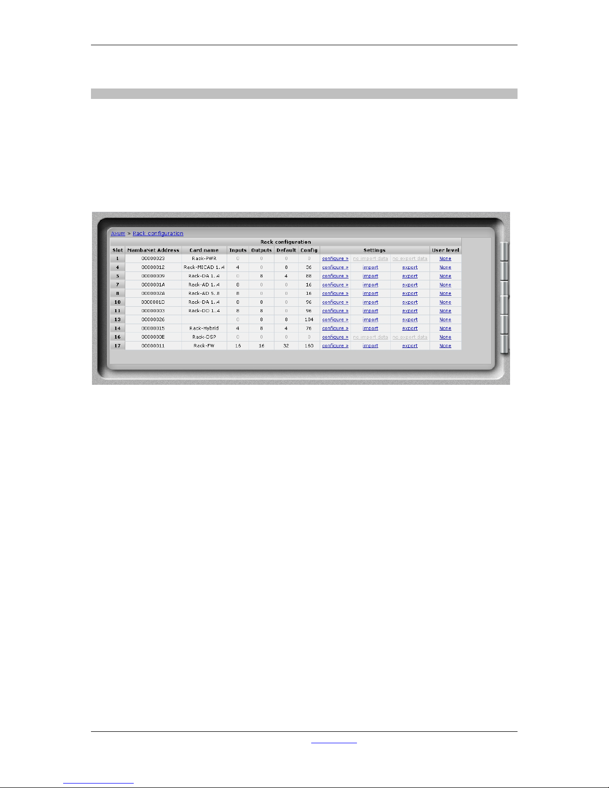
You can see an overview of the cards in the rack on this page. You can find information like the slot
number, MambaNet address, card name, number of inputs and outputs.
The link Configure will go to a page for connecting objects of the card to Axum engine’s functions.
You can consider this as the remote control configuration. For example you can connect:
• Start/stop functionality to remote outputs
• Source gain functionality to MIC gain
• Speaker level to CRM output level
• etc. etc.
Figure 26: Rack configuration
• Slot
Slot number where the I/O card is located.
• MambaNet Address
Show information on the internal used MambaNet addresses
• Node name
Logical name of the node
• Inputs
Number of mono input channels
• Outputs
Number of mono output channels
• Default
Number of objects that have a default value set.
• Config
Number of objects that are configured to an engine function.
• Import/Export
Once you have configured the defaults and used engine functions you can export and import
these settings. With export the current configuration is stored in the database, where you have
to give a logical name (e.g. Module 5-8). With import you can restore a configuration to the
same or a different node (of the same type). When you import Module 5-8 with an offset of -4
the configuration will be as you expect Module 1-4.
Page 44
A·X·U·M User Manual Version 2.5 - 2011-01-28
AXUM from D&R - Phone: +31 294 418014 - E-Mail: info@d-r.nl - 44 -
• User level
Here you can define which c ons ole user level the I/O card will use (e.g. for its GPIs).
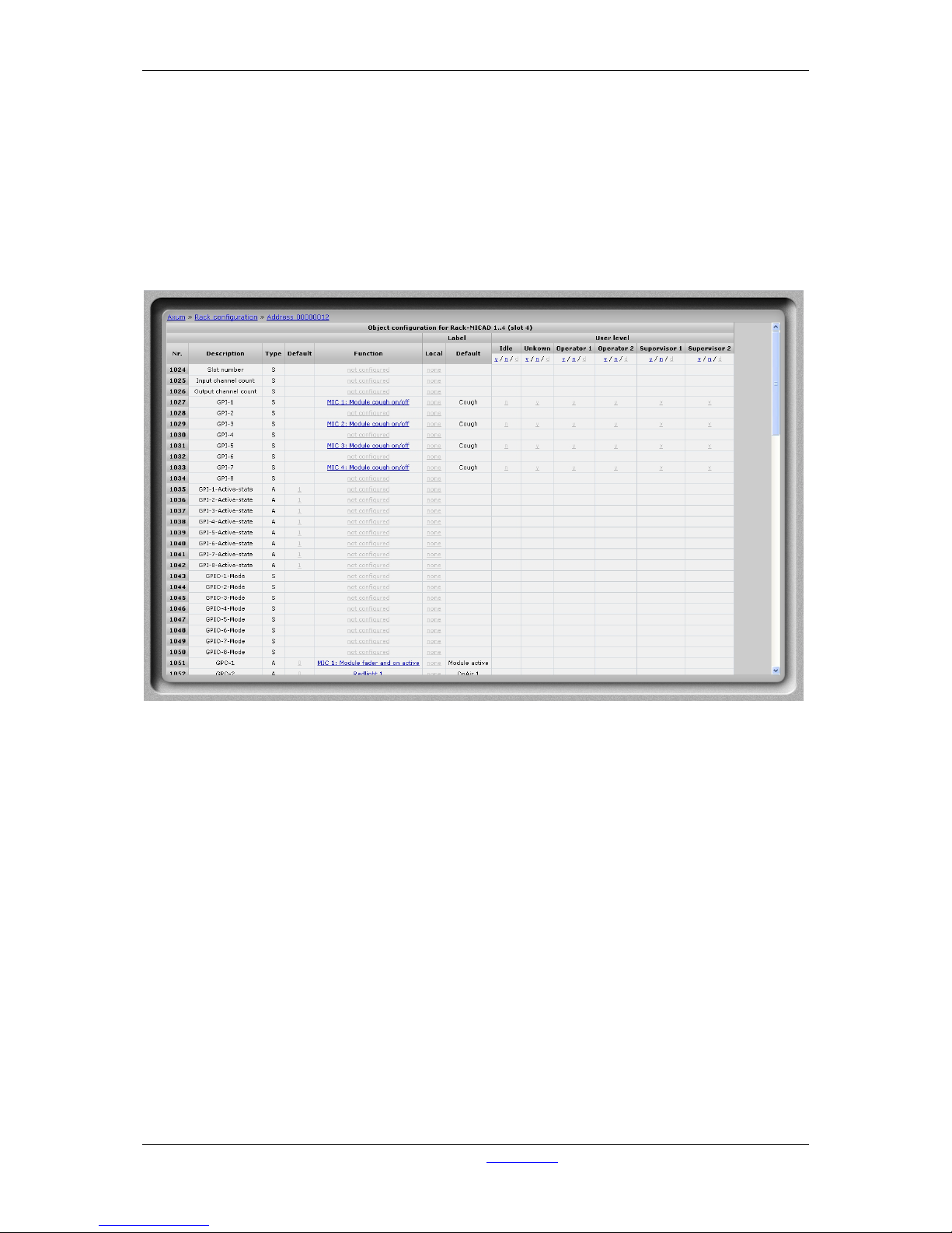
• Configure
The page shown below gives an indication how the CRM output level objects connect to the
Speaker level engine functions. By following the links, you can reconfigure the functions that
connect to the objects. The sensor and actuator data types determine which function assigns
to the object.
For a complete list of the functions, you can look up chapter 20 Appendix C – Engine
functions..
Figure 27: Node object configuration (to Axum functions)
• Label
Here you may change the label, which is a shortcut for the selected function, if none is given
the default function label will be used (the label will appear in the remote configuration
software).
• User level
Per user level you can overwrite the default level per function. If y is selected the function will
be available in the selected user level. If n is selected the function won´t be available. if the y/n
value is shown light gray, the function default user level is used.
In the column headers you may toggle the user level for all objects in the node.
Page 45
A·X·U·M User Manual Version 2.5 - 2011-01-28
AXUM from D&R - Phone: +31 294 418014 - E-Mail: info@d-r.nl - 45 -
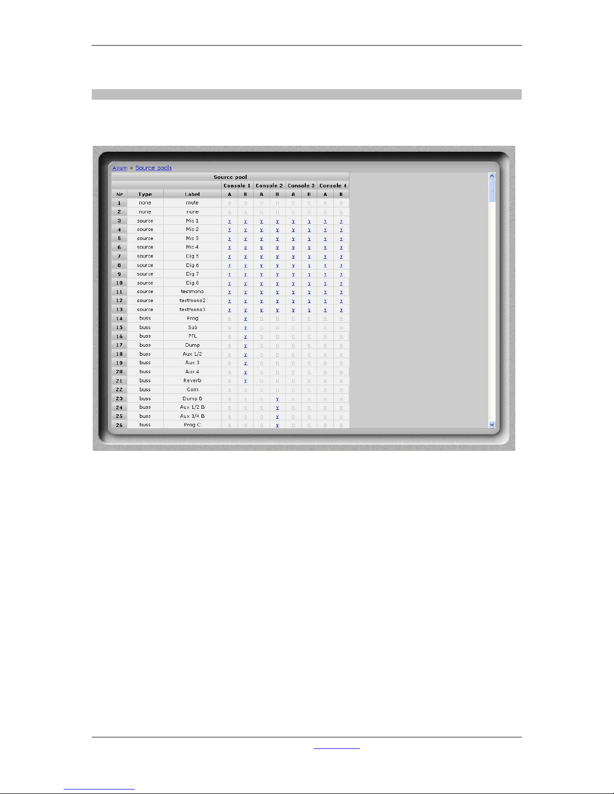
6.1.16 Source pools
You can see an overview of the source pools on this page. A source pool may be assigned to a user
to give them a comfortable source list for selection from the control surface.
Figure 28: Source pool configuration
• Type
Type of the source.
• Label
Name of the source.
• Source pool
Per console there are 2 source pools A/B
If y is selected the source will be available in the selected source pool. If n is selected the
source won´t be available.
Page 46
A·X·U·M User Manual Version 2.5 - 2011-01-28
AXUM from D&R - Phone: +31 294 418014 - E-Mail: info@d-r.nl - 46 -
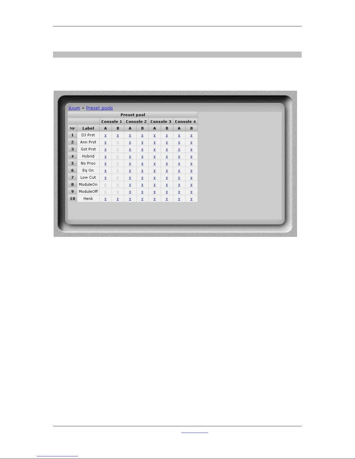
6.1.17 Preset pools
You can see an overview of the preset pools on this page. A preset pool may be assigned to a user to
give them a comfortable source list for selection from the control surface.
Figure 29: Preset pool configuratio n
• Label
Name of the preset.
• Preset pool
Per console there are 2 preset pools A/B
If y is selected the preset will be available in the selected preset pool. If n is selected the
preset won´t be available.
Page 47
A·X·U·M User Manual Version 2.5 - 2011-01-28
AXUM from D&R - Phone: +31 294 418014 - E-Mail: info@d-r.nl - 47 -
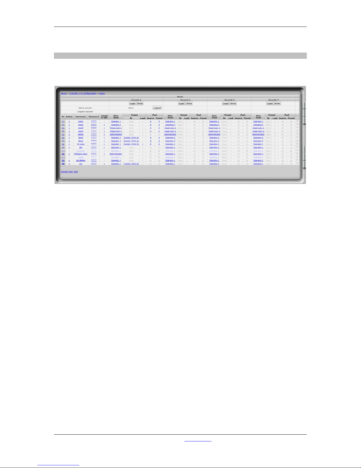
6.1.18 Users
You can see an overview of the users on this page. You can see the user level/preset per user and
per console.
Figure 30: User configuration
• Login
Here you can login as a user to the selected console.
• Write
Here you can write the selected user to a plugged in chipcard.
• Active account
The account that is currently active in this console (this may be different from the chipcard if
overruled by software).
• Chipcard account
The name of the user of a plugged in chipcard, will appear here.
• Add
With this button you can add the user from a chipcard to the AXUM system.
• Nr
Here you can reposition the user to make the list in a convenient order.
• Active
You may disable an account using this switch.
• Username
Here you can enter the name of the user.
• Password
Here you can enter the password of the user.
• Logout to idle
Removal of the chipcard can be used to stay in the last user or to jump to the idle situation.
• User level
Here you can select the user level of the user (see also 6.1.14 Surface configuration and
6.1.15 Rack configuration)
Page 48

A·X·U·M User Manual Version 2.5 - 2011-01-28
AXUM from D&R - Phone: +31 294 418014 - E-Mail: info@d-r.nl - 48 -
• Console preset
It is possible to select a console preset which will be loaded if the user logs in.
• Pool
Per console you can select which preset and which source pool the user may use. Per pool
you can choose between A, B or all. (see also 6.1.16 Source poo ls and 6.1.17 Preset pools)
• Delete
When you click on this column the user will be deleted.
Create new user
By clicking on this link a popup will appear where you have to setup the username and password for
the new user.
Page 49
A·X·U·M User Manual Version 2.5 - 2011-01-28
AXUM from D&R - Phone: +31 294 418014 - E-Mail: info@d-r.nl - 49 -
6.2 System configuration
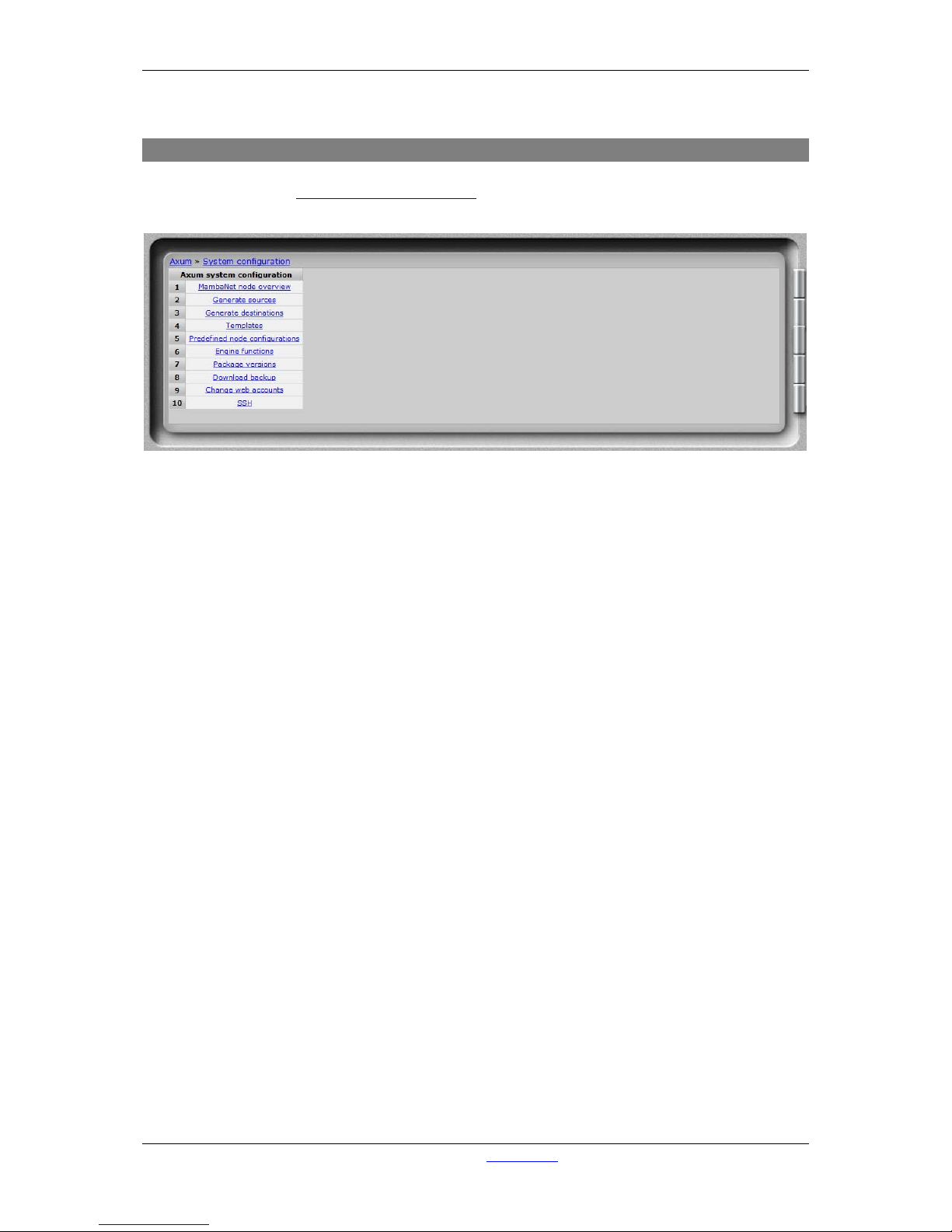
If you browse to the url
http://192.168.0.200/system (where 192.168.0.200 should be your local AXUM
IP address) you have a system menu with give some management/service possibilities.
Figure 31: Service menu
• MambaNet node overview
Will show all nodes that are found in the local Ethernet network.
• Generate sources
WARNING: this function deletes all sources and their configuration.
After all sources are deleted, it will generate new sources regarding the ‘rack layout’ found.
• Generate destinations
WARNING: this function deletes all destinations and their configuration.
After all sources are deleted, it will generate new sources regarding the ‘rack layout’ found.
• Templates
Shows a list of all known node types. The learner did read these templates from the nodes.
• Predefined node configurations
Shows a list of configurations stored by the export function in surface/rack configuration.
• Engine functions
Shows a list of all engine functions available.
• Package versions
Shows the packages, version and build/install date.
• Download backup
Downloads a file wh ic h is a complete image of the internal flash disk (under development).
• Change web accounts
Here you can change the password for the webserver console configuration and system
configuration.
• SSH
Here the SSH server (port 22) may be disabled or enabled for remote service.
Page 50
A·X·U·M User Manual Version 2.5 - 2011-01-28
AXUM from D&R - Phone: +31 294 418014 - E-Mail: info@d-r.nl - 50 -
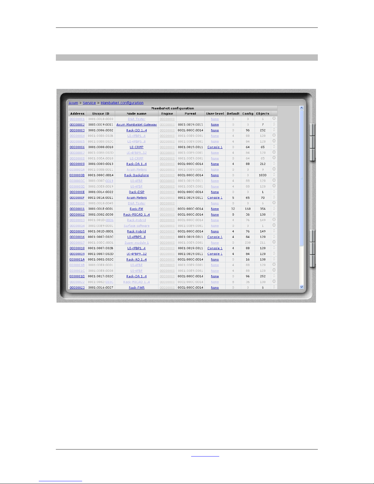
6.2.1 MambaNet node overview
This pages shows all nodes found in the local Ethernet network. Also nodes that are not online can be
seen as ‘grayed out’ nodes.
Figure 32: MambaNet node overview
• Address
This is the MambaNet address used in this setup. This address is used for all communication
and configuration.
• UniqueID
This shows the ‘ManufacturerID:ProductID:UniqueID’ in hexadecimal format. When a node is
offline you will see the ‘UniqueID’ is a link. This can be used to transfer the configuration of the
offline node to another online node of the same type.
• Node name
Here you can change a node name to a logical correct name, this makes identification in the
system easier.
• Engine
If you use multiple engines into a single Ethernet you can give here which engine is used by
the node. Address ‘00000000’ means the node communicates with all engines in parallel;
Page 51

A·X·U·M User Manual Version 2.5 - 2011-01-28
AXUM from D&R - Phone: +31 294 418014 - E-Mail: info@d-r.nl - 51 -
which is most easy for systems with only one engine.
• Parent
Easy node can store its parent node so we can determine the physical-location of nodes.
• User level
Here you can define which console user level the node will use.
• Default, Config and Objects
This column shows the numbers of objects and how many have a default value or
configuration
• Delete/Refresh
Grayed out nodes may be deleted by pressing the delete image.
WARNING: When a node is deleted the configuration is also removed!
Only nodes do not have a delete image, but a refresh image. This can be used to force a
refresh of the node name and parent.
Page 52
A·X·U·M User Manual Version 2.5 - 2011-01-28
AXUM from D&R - Phone: +31 294 418014 - E-Mail: info@d-r.nl - 52 -
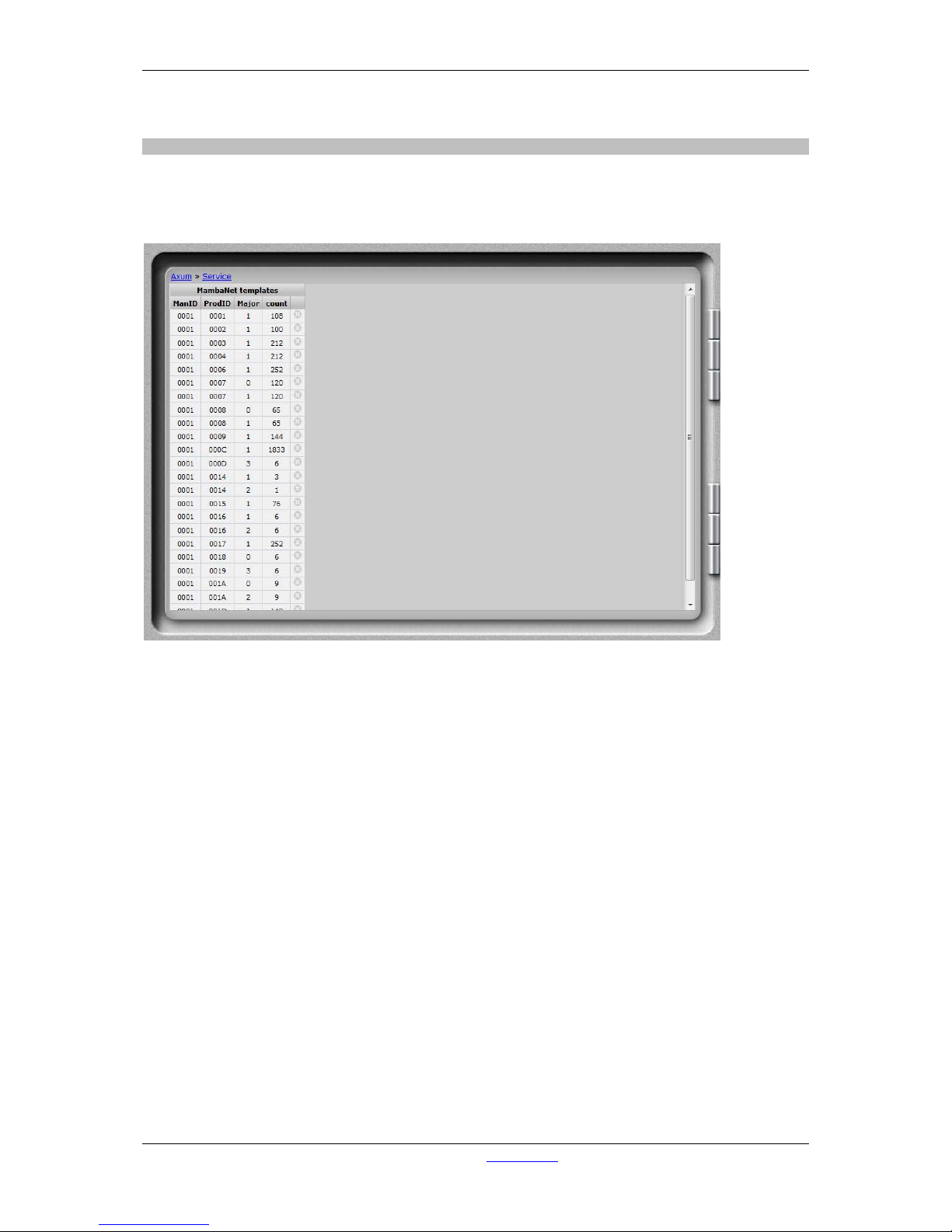
6.2.2 Templates
The learner continuously checks for unknown nodes. When a unknown node is found it will read the
object information and store it in the database. A template is unique by:
ManufactureID, ProductID and Major Firmware Revision.
Figure 33: Node templates
• Count
Shows the number of objects that are located in this template.
• Delete
When because of a failure a template is wrong you may delete it so the learn er wil l read the
information again.
Page 53
A·X·U·M User Manual Version 2.5 - 2011-01-28
AXUM from D&R - Phone: +31 294 418014 - E-Mail: info@d-r.nl - 53 -
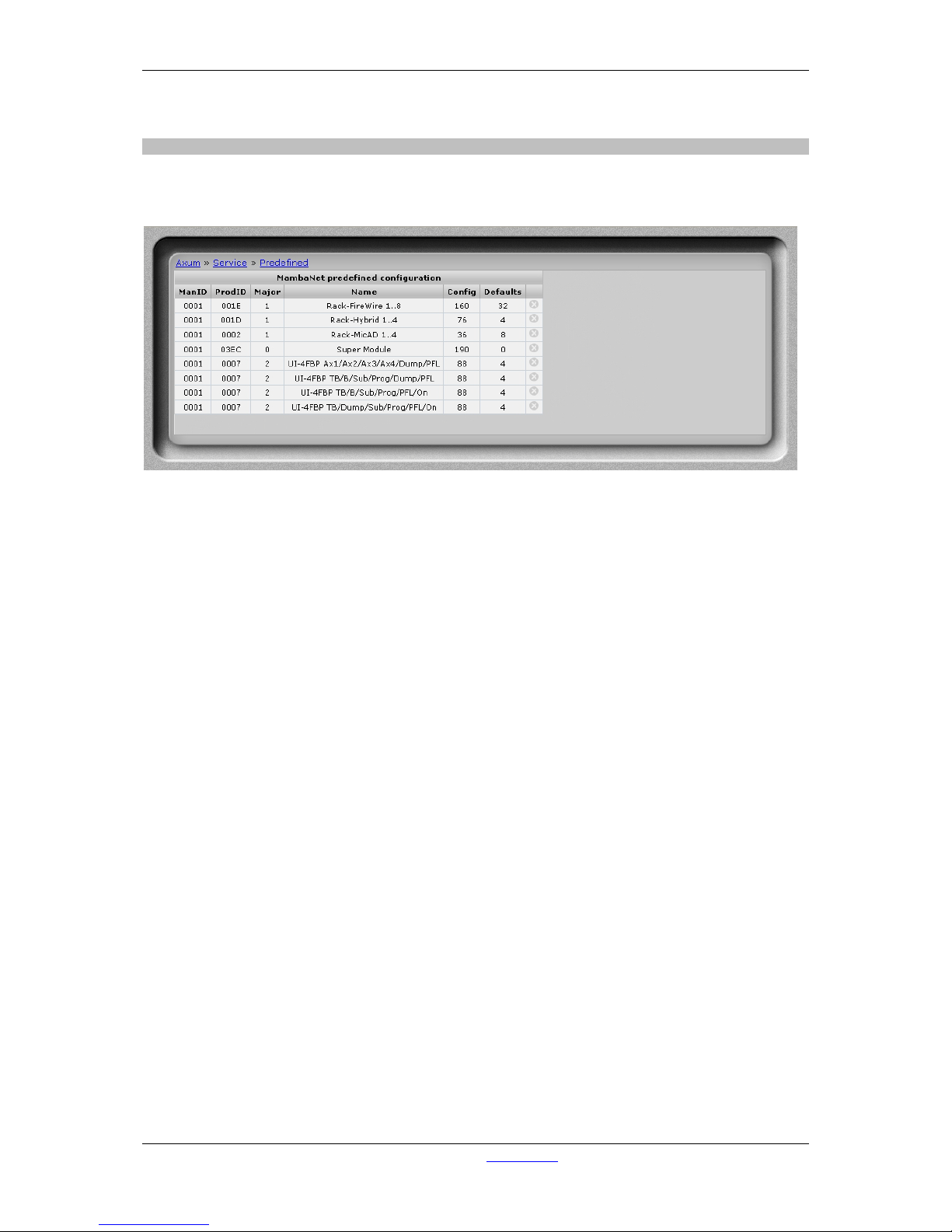
6.2.3 Predefined node configurations
The configurations that are exported are listed here. When you mistakenly did export a configuration
you may delete it from here.
Figure 34: Stored configura tions
• Config
Config gives the number of configured objects that are stored.
• Default
Default gives the number of configured defaults that are stored.
Page 54
A·X·U·M User Manual Version 2.5 - 2011-01-28
AXUM from D&R - Phone: +31 294 418014 - E-Mail: info@d-r.nl - 54 -
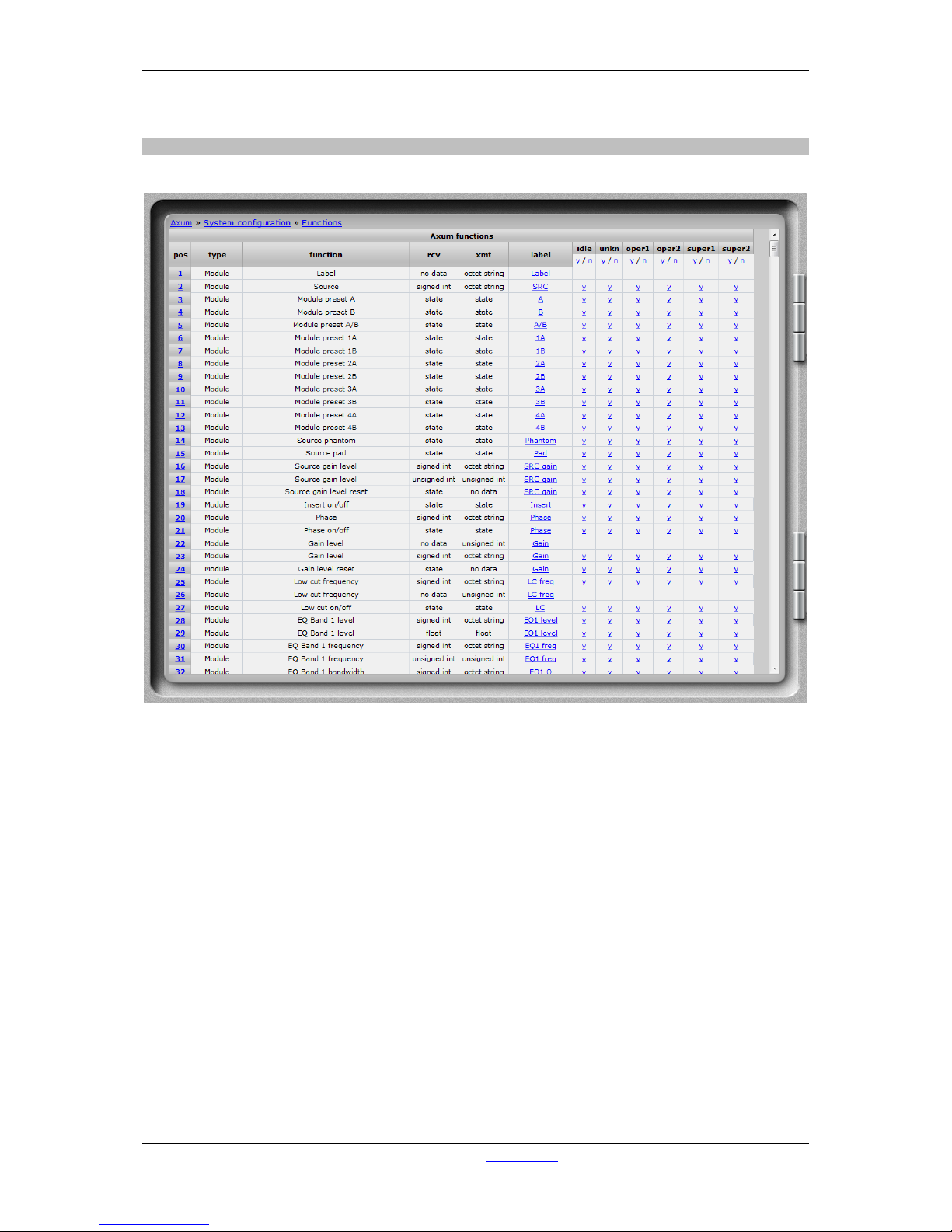
6.2.4 Engine functions
This is a list of all available engine functions.
Figure 35: Engine functions
• Pos
Here it is possible to reposition the functions for easier/faster access in the surface/rack
configuration menu’s
• Type
Shows the group the functions belongs to and determines which number range is used.
- Module: 1-128
- Busses: 1-16
- Monitor busses: 1-16
- Global: 0
- Source: 1-1280
- Destination: 1-1280
• Function
Is the description of the engine function
• Rcv
The receive column shows which datatype is required at the object-sensor to be able to
control this functions.
Page 55
A·X·U·M User Manual Version 2.5 - 2011-01-28
AXUM from D&R - Phone: +31 294 418014 - E-Mail: info@d-r.nl - 55 -
• Xmt
The transmit column shows which datatype is required at the object-actuator to be able to
receive data from the engine.
• Label
This label will be used if default function label for remote software applications. It can be
changed here globally. In the surface/rack configuration you may give labels per configured
object-function.
• User levels
For each user level you can select the default state, if ‘y’ this function can be used for this user
level, if ‘n’ this functions can not be used for this user level. The function default setting can be
overruled in the node configuration.
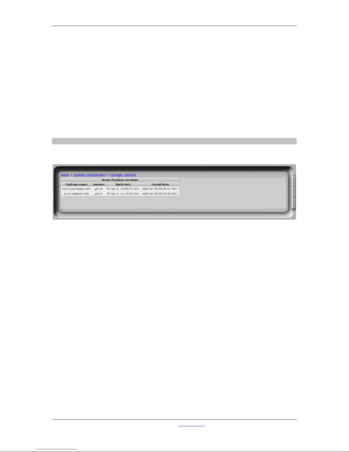
6.2.5 Package ve rsio ns
This page shows the installed packages with their version number, build and install date.
Figure 36: Package versions
Page 56
A·X·U·M User Manual Version 2.5 - 2011-01-28
AXUM from D&R - Phone: +31 294 418014 - E-Mail: info@d-r.nl - 56 -
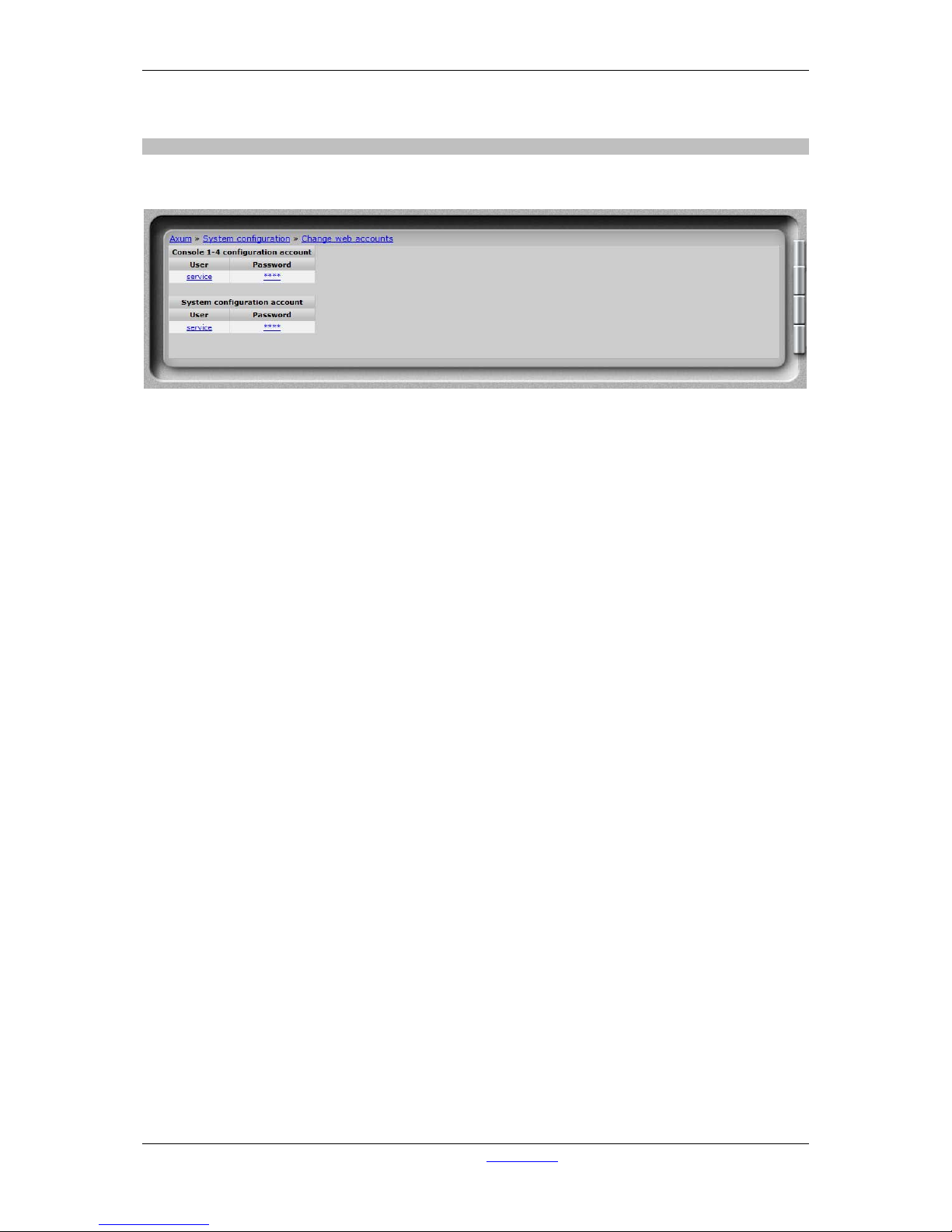
6.2.6 Change web accounts
The webserver requires authentication. On this page you change the username and password.
Figure 37: Change password
Page 57
A·X·U·M User Manual Version 2.5 - 2011-01-28
AXUM from D&R - Phone: +31 294 418014 - E-Mail: info@d-r.nl - 57 -
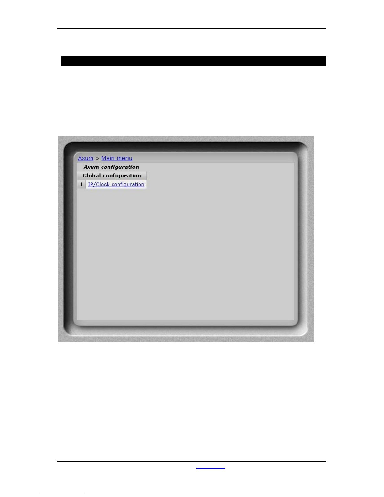
7 Surface(s) website
To set the time displayed in the meter of the console.
Simply enter the IP address of the console in your browser and log-on to the configuration pages.
By default the IP Address is: http://192.168.0.234
(at first time startup you can use a network or cross wire with a static IP given to your network
interface, e.g. 192.168.0.10).
On the console website, you find the ip/clock configuration:
Figure 38: Console website
Page 58
A·X·U·M User Manual Version 2.5 - 2011-01-28
AXUM from D&R - Phone: +31 294 418014 - E-Mail: info@d-r.nl - 58 -
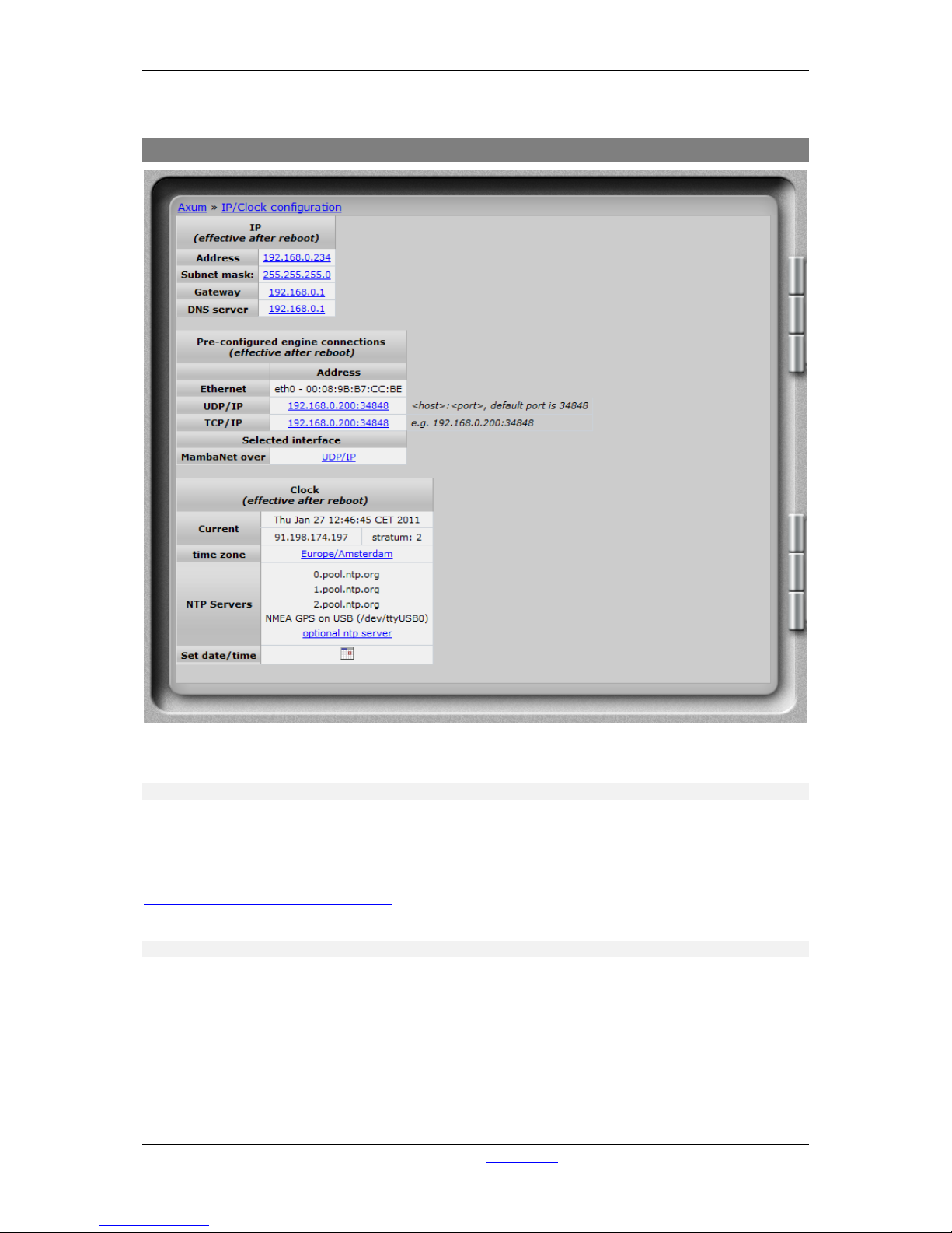
7.1 IP/Clock configuration
Figure 39: IP/Clock configuration
7.1.1.1 IP
Here you can setup the network settings to be compatible with the required settings in your situation
and you can set the time zone to where you are.
It’s possible to change the IP, subnet, gateway and DNS server address by clicking on the address.
For more information on IP addressing:
http://en.wikipedia.org/wiki/IP_address
7.1.1.2 Pre-configured engine connections
An surface may connect to a rack via different protocols, here you may select the destination IP and
port to connect to.
In the field ‘MambaNet over’ you select the protocol to use, where Ethernet may be used in a LAN
(with only one rack) and UDP or TCP may be used in LAN and WAN; even with multiple consoles
hooked up in the LAN (They should have ‘MambaNet over Ethernet’ enabled).
Page 59

A·X·U·M User Manual Version 2.5 - 2011-01-28
AXUM from D&R - Phone: +31 294 418014 - E-Mail: info@d-r.nl - 59 -
7.1.1.3 Clock
To change the time zone, click on the used time zone (in our example ‘Europe/Amsterdam’). You can
select the desired time zone in the list box.
The AXUM uses the NTP protocol for accurate clock synchronization. In the section ‘current’ you find
the IP address of the used ‘clock master’ and its ‘stratum’. For more information on NTP:
http://en.wikipedia.org/wiki/Network_Time_Protocol
When IP and DNS settings are setup correct, the AXUM will automatically synchronize to a pool of
time servers. The AXUM is also able to use a GPS receiver via USB for time synchronization. next,
the AXUM may function as a NTP server for the surfaces. There for, on the webserver of the control
surfaces you can configure the 'optional ntp server' and fill in the IP address of the ntp server (e.g.
192.168.0.200).
Set date/time may be used on system without any synchronization to set the correct time.
In the popup window it is possible to give to correct time and if you click on the ‘day’ it will become
direct changed/activated.
Remember that all other changes (NTP and IP settings) will become effective after reboot.
Page 60

A·X·U·M User Manual Version 2.5 - 2011-01-28
AXUM from D&R - Phone: +31 294 418014 - E-Mail: info@d-r.nl - 60 -
8 Block diagrams – Must be created
With all configuration options, it is possible to make many different systems using a single I/O rack.
We will show some example block diagrams on possible setups within an Axum system.
32 stereo module, 16 stereo buss and 4 stereo monitor buss console:
Note:
These diagrams will follow in future manuals, sorry
Page 61
A·X·U·M User Manual Version 2.5 - 2011-01-28
AXUM from D&R - Phone: +31 294 418014 - E-Mail: info@d-r.nl - 61 -
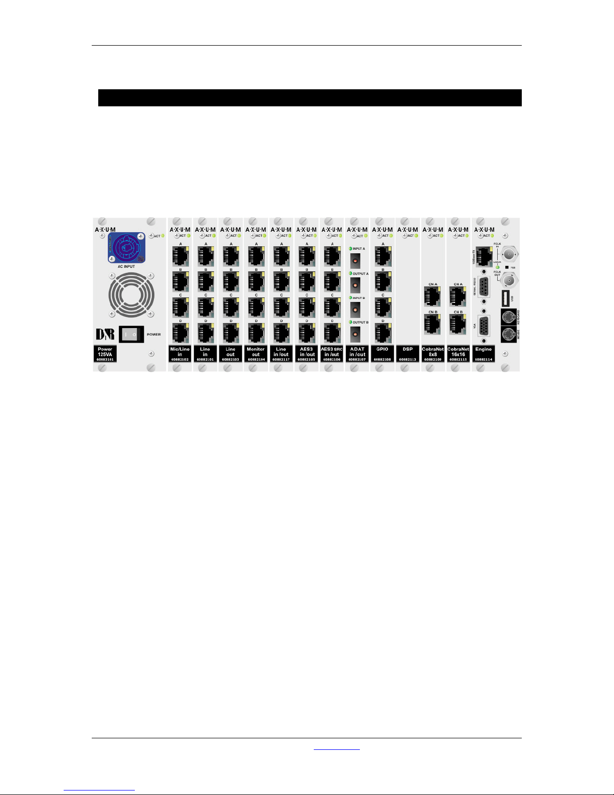
9 I/O Rack description
The AXUM digital audio s ystem has a 19” rack (f or 21 slots ) that requires at least one power s uppl y (3
slots) and one engine card (2 slots). You then have s pace for a maximum of 16 in and output cards.
Because the AXUM is a m odular system it is up t o you how man y in and output cards are necessary
to do the job.
For the connections, we use standard RJ 45; an example f or other connectors is ADAT that us es the
well-known ADAT optical c onnect or. Conn ection bet ween de RJ4 5s in the r ack and your patch un its is
by standard STP (Shielded Twisted Pair) cable.
Figure 40: AXUM Digital audio system 19” Rack
Page 62
A·X·U·M User Manual Version 2.5 - 2011-01-28
AXUM from D&R - Phone: +31 294 418014 - E-Mail: info@d-r.nl - 62 -
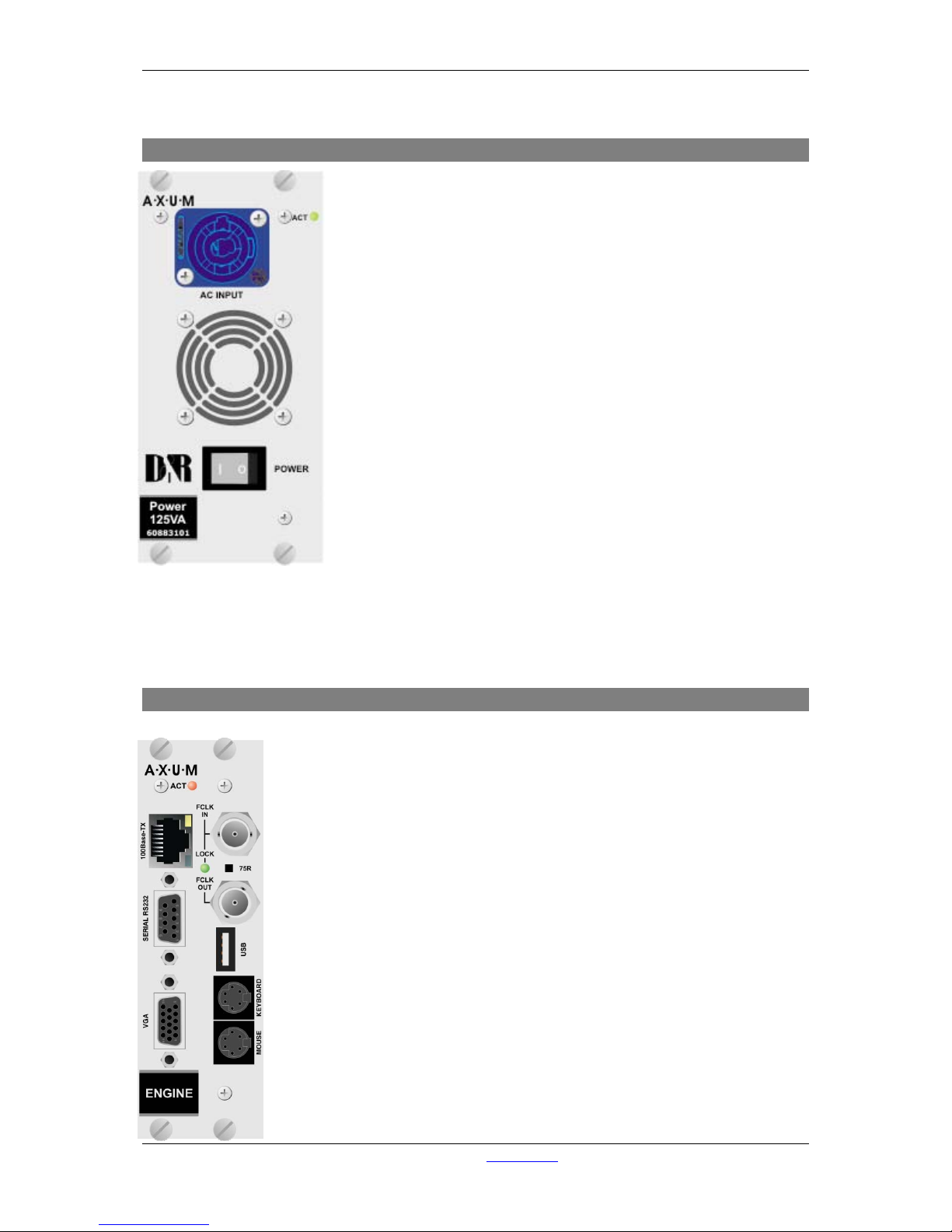
9.1 Power supply
At the far left in the I/O RACK is the pos ition where the power supply
Card is inserted; an optional s econd power suppl y card can be inserted
alongside this first one. With two power supplies, you have created
automatic power supply redundancy.
The LED will blink green to s how the power supply is up and running.
At failure of the loc al power, this LED activity will be blinking red or not
blinking at all.
The NEUTRIK
TM
PowerCONTM will feed 100-240V power to the supply.
With the power switch you can turn off the local power supply.
WARNING:
Before you insert a second power supply please turn on the power
of this second unit first to make sure you will not short the internal
power-lines.
9.2 Engine
The engine is the controller card of the AXUM Digital audio system. This card has
a fixed location at the far right side. For proper functioning of the system, you
absolutely have to insert this card to your digital audio systems network.
The RJ45 is a default 100Mbit Ethernet port and over this network connection, the
following information is send:
• MambaNet: control protocol
• HTTP: Configuration of your engine via web server
• FTP: Firmware/configuration update and backup via a file server.
Currently, the serial RS232, VGA, Keyboard, mouse and USB connection can be
used for service purposes only.
Via the BNC connectors you synchronize this entire rack to an external frame
clock as well as to remote equipment with the clock of this 19”rack.
With the 75R switch, you can turn on/off a 75-Ohm termination on the receiving
frame clock connector.
The ACT(ive) LED will blink to show proper functioning of the Engine card.
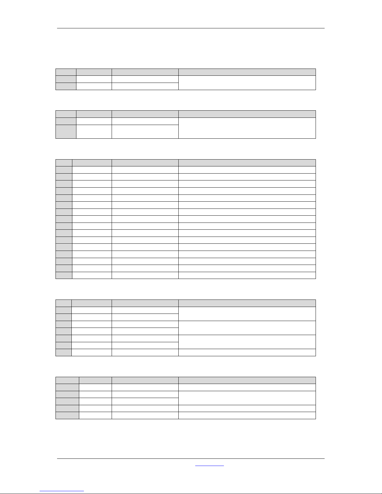
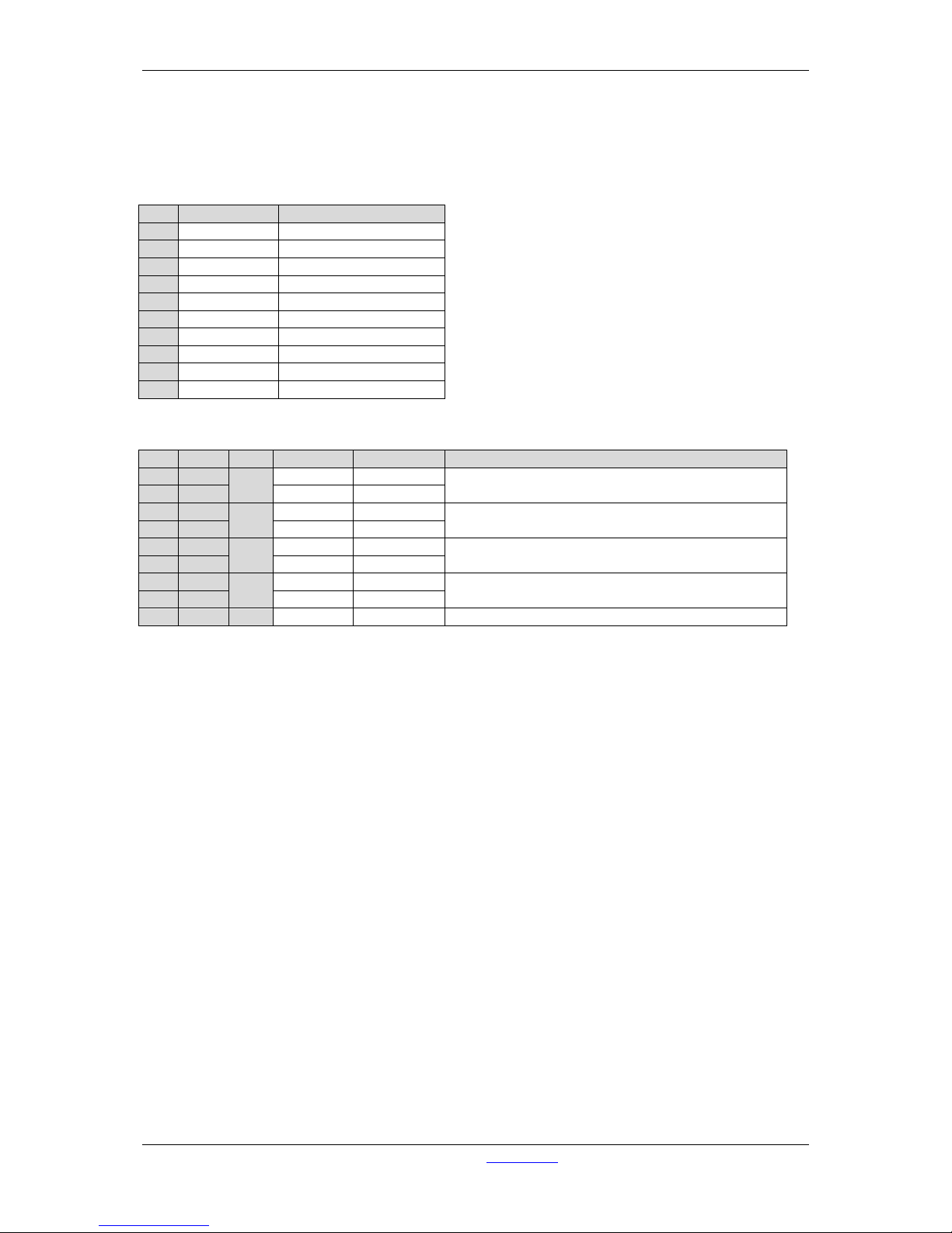
On the next page, you find the pin information for all the connectors:
Page 63
A·X·U·M User Manual Version 2.5 - 2011-01-28
AXUM from D&R - Phone: +31 294 418014 - E-Mail: info@d-r.nl - 63 -
Pin
Pin name
Function
Comment
1
Centre
Frame Clock in
32kHz, 44.1kHz, 48kHz, +/- 100ppm, +5V TTL,
switchable 75Ohm terminator.
GND
GND
Ground Frame Clock in
Table 9-1: Frame clock input BNC
Pin
Pin name
Function
Comment
1
Centre
Frame Clock Out
32kHz, 44.1kHz, 48kHz, +5V TTL, imp.: 75Ohm
GND GND
Ground Frame Clock
out
Table 9-2: Frame clock output BNC
Pin
Pin name
Function
Comment
1
Red
Red Video Out
Red Video
2
Green
Green Video Out
Green Video
3
Blue
Blue Video Out
Blue Video
4
nc
5
GND Hsync
GND Horizontal Sync
6 Red_RTN
Red Video Return
Red Video
7
Green_RTN
Green Video Return
Green Video
8
Blue_RTN
Blue Video Return
Blue Video
9
+5V
Power DDC
DCC
10
GND
GND (Vsync, DCC)
Ground
11
nc
12
DDDA
Data DDC
DCC
13
Hsync
Horizontal Sync
Horizontal Sync
14
Vsync
Vertical Sync
Vertical Sync
15
DDCK
CLK DDC
DCC
S
Shield
Ground
Table 9-3: VGA 15p D-Sub connector
Pin
Pin name
Function
Comment
1
KB Data
Keyboard/Mouse Data
Keyboard/Mouse Connection
5
KB CLK
Keyboard/Mouse CLK
2
not connected
6 4 PWR
+5V Power
Power Connection
3
GND
Ground
S
Shield
Ground
Ground
Table 9-4: Keyboard & Mouse mini DIN connector
Pin
Pin name
Function
Comment
1a/b
VBUS
+5V Power
Supply power
2a/b
nUSB
USB Data outface
USB
3a/b
USB
USB Data inface
4a/b
GND
Ground
Ground
S
Shield
Ground
Ground
Table 9-5: USB connector (2x)
Page 64
A·X·U·M User Manual Version 2.5 - 2011-01-28
AXUM from D&R - Phone: +31 294 418014 - E-Mail: info@d-r.nl - 64 -
Pin
Pin name
Function
1
DCD
Carrier Detect
6
DSR
Data Set Ready
2
RD
Receive Data
7
RTS
Request To Send
3
TD
Transmit Data
8
CTS
Clear To Send
4
DTR
Data Terminal Ready
9
RI
Ring Indicator
5
GND
Ground
S
Shield
Ground
Table 9-6: RS232 9pin SUB-D connector
Pin
Con.
Pair
Pin name
Function
Comment
1
1A 1 TX +
Ethernet
Ethernet TX 10/100BASE-T
2
1B
TX -
Ethernet
3
2A 2 RX+
Ethernet
Ethernet RX 10/100BASE-T
6
2B
RX-
Ethernet
5
3A 3 NC
4
3B
NC 7
4A 4 NC
8
4B
NC S
GND
S
Shield
GND
Ground
Table 9-7: Ethernet RJ45 connection
Page 65
A·X·U·M User Manual Version 2.5 - 2011-01-28
AXUM from D&R - Phone: +31 294 418014 - E-Mail: info@d-r.nl - 65 -
9.3 GPIO
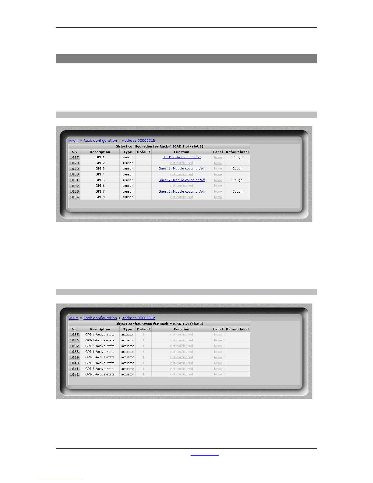
In rack configuration you can connect objects of MambaNet nodes to AXUM engine functions. Here
you can also configure the GPIO objects of your I/O cards (MambaNet nodes). B y follow ing the links,
you can reconfigure the functions that connect to the objects. The sensor and actuator data types
determine which function assigns to the object.
For a complete list of the functions, you can look up chapter 20 Appendix C – Engine functions.
9.3.1 GPI
Figure 41: GPI configuration
• Function
Here you may select which engine function is connected to the object. To use the GPI
functions you must select the hardware jumper setting TLL mode on the board (see chapter
11.3.1 GPIO TTL/Relay selection). The default jumper setting is GPO-Relay for all cards
except for the MIC input card. The default jumper setting for the MIC input card is GPIO-TTL
for GPIO 1, 3, 5 and 7 and GPO-Relay for GPIO 2, 4, 6 and 8.
9.3.2 GPI Active-state
Figure 42: GPI Active-state configuration
• Default
The gray value ‘1’ is the startup default, this may be changed by assigning a custom value (0
Page 66
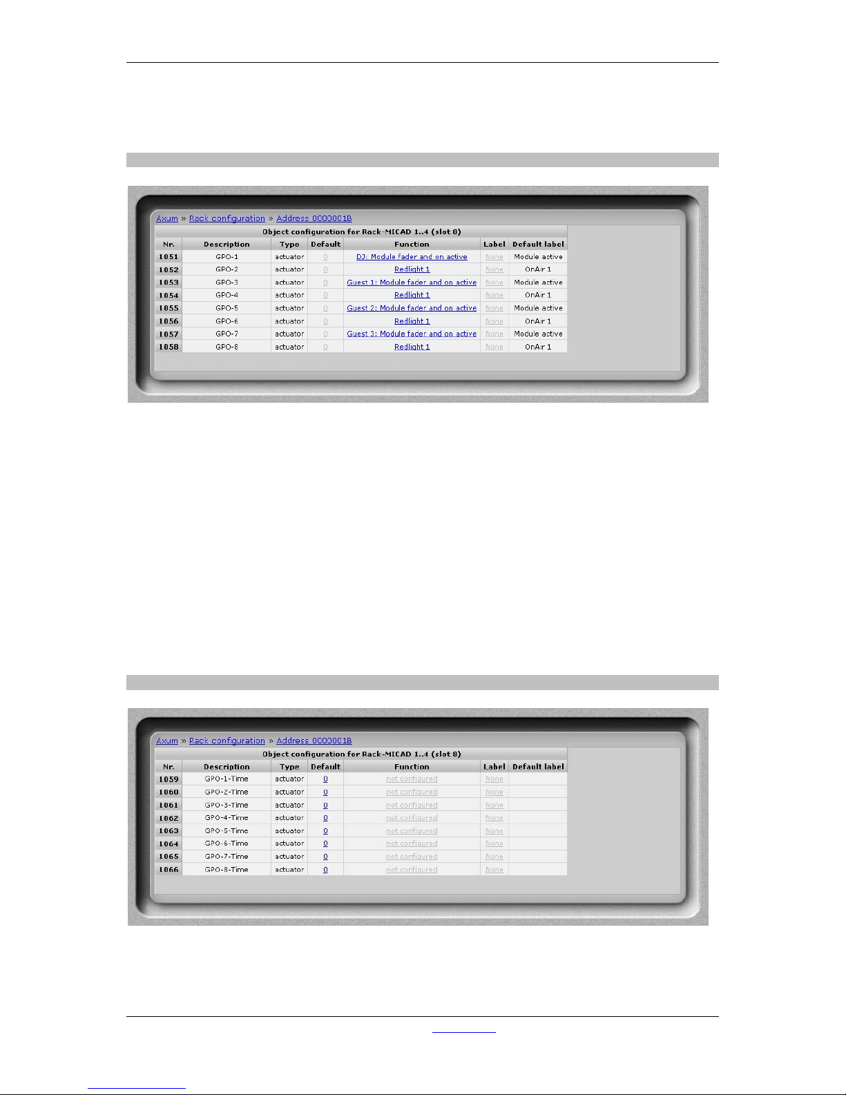
A·X·U·M User Manual Version 2.5 - 2011-01-28
AXUM from D&R - Phone: +31 294 418014 - E-Mail: info@d-r.nl - 66 -
or 1). A value of ‘1’ makes sure that if the GPI is +5V the function is made active. The value ‘0’
makes sure that if the GPI is 0V the function is made active.
When you submit an empty box the object returns to the startup default value.
9.3.3 GPO
Figure 43: GPO configuration
• Default
The gray value is the startup default, this may be changed by assigning a custom value(0 or
1). A value of ‘1’ makes sure the GPO is active at startup. A value of ‘0’ makes sure the GPO
is inactive at startup. The GPO output state is also depending on the GPO active-state setting.
When you submit an empty box the object returns to the startup default value.
• Function
Here you may select which engine function is connected to the object. To use the GPO
functions you should maybe change the hardware jumper setting on the board (see chapter
11.3.1 GPIO TTL/Relay selection) to enable the given engine function The default jumper
setting is GPO-Relay for all cards except for the MIC input card. The default jumper setting for
the MIC input card is GPIO-TTL for GPIO 1, 3, 5 and 7 and GPO-Relay for GPIO 2, 4, 6 and
8.
9.3.4 GPO Time
Figure 44: GPO Time configuration
• Default
The gray value is the startup default, this may be changed by assigning a custom value.
Page 67
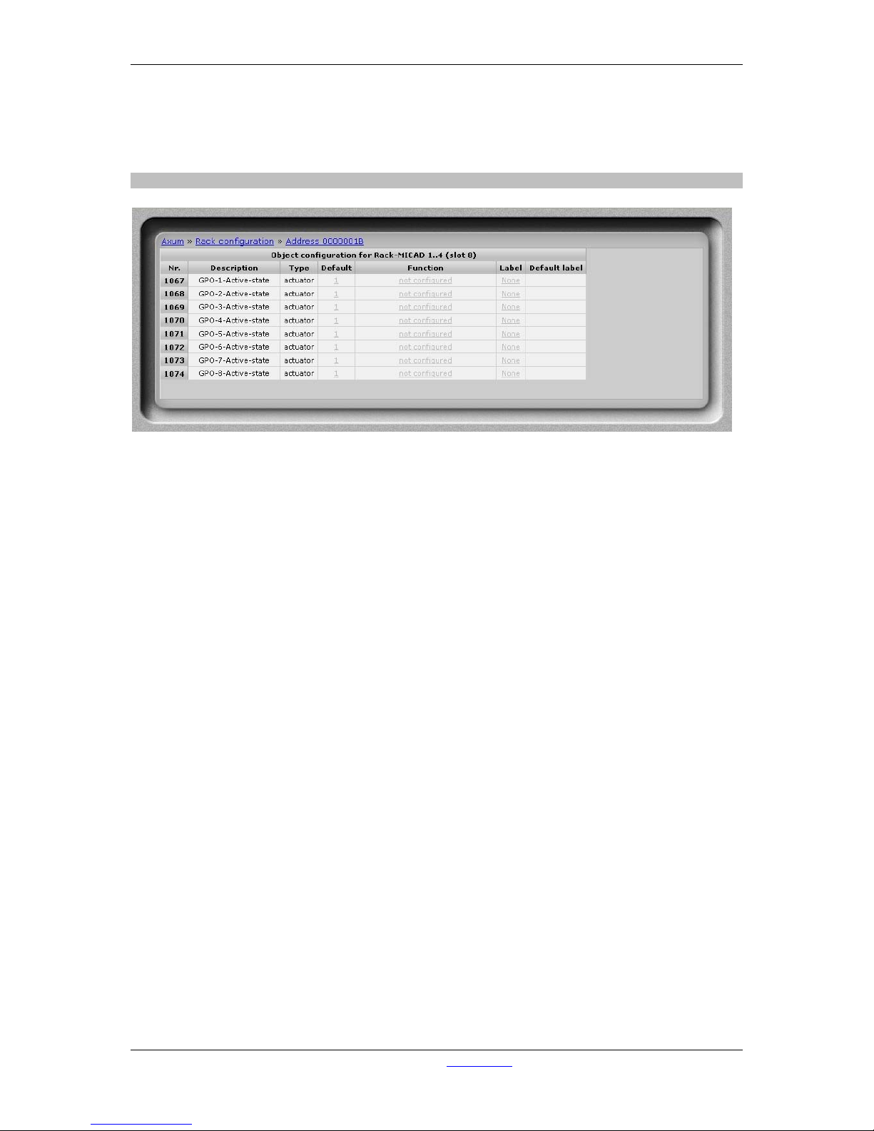
A·X·U·M User Manual Version 2.5 - 2011-01-28
AXUM from D&R - Phone: +31 294 418014 - E-Mail: info@d-r.nl - 67 -
The value must be between 0 – 250, where 0 is a continuous signal and 1 - 250 is the pulse
width in milliseconds.
When you submit an empty box the object returns to the startup default value.
9.3.5 GPO Active-state
Figure 45: GPO Active-state configuration
• Default
The gray value ‘1’ is the startup default, this may be changed by assigning a custom value (0
or 1). A value of ‘1’ makes sure that if the GPO is active the output is +5V in TTL mode or A/B
connected for relay mode. The value ‘0’ makes sure that if the GPO is active the output is 0V
in TTL mode or A/B disconnected in relay mode.
When you submit an empty box the object returns to the startup default value.
Page 68
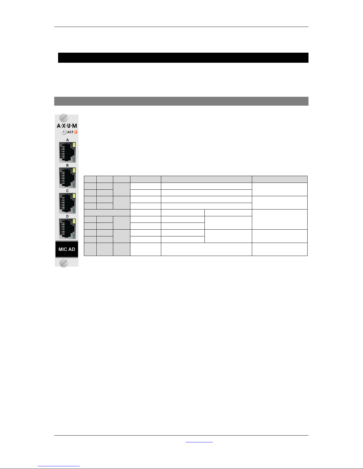
A·X·U·M User Manual Version 2.5 - 2011-01-28
AXUM from D&R - Phone: +31 294 418014 - E-Mail: info@d-r.nl - 68 -
10 Available I/O rack cards
Depending on your audio-connections, you can select the I/O cards.
The next paragraphs will give you a detailed overview on the currently available cards.
10.1 MIC input card
There are four balanced MIC inputs available on each card.
Each RJ45 connector represents a MIC input and two GPIO’s which can be connected to
the 19” patch panels with a shielded twisted pair (STP) cable.
On each MIC input you can individual activate the +48V phantom power and PAD.
For each GPIO you can choose, by way of a hardware jumper on the board, between TTL
Input/output or Photo-MOS relay output see chapter 11.3.1 GPIO TTL/Relay selection. For
software configuration see chapter 9.3 GPIO.
Table 10-1: MIC RJ45 connection
Pin
Con.
Pair
Pin name
Function
Comment
1
1A 1 +Audio 1
MIC input in-phase
Imp. 2kΩ
max. level +20dBu
2
1B
-Audio 1
MIC input out-phase
3
2A 2 +Audio 2
not used
6
2B
-Audio 2
not used
If jumper TTL-GPIO If jumper GPO
see chapter 11.3.1
5
3A 3 GPIO1a
GP-Out
(TTL)
Photo MOS relay
(max 50V, 200mA)
4
3B
GPIO1b
nGP-In
(TTL)
7
4A 4 GPIO2a
GP-Out
(TTL)
Photo MOS relay
(max 50V, 200mA)
see chapter 11.3.1
8
4B
GPIO2b
nGP-In
(TTL)
S GND S Shield GND
Audio ground and
reference for GP-In
Page 69
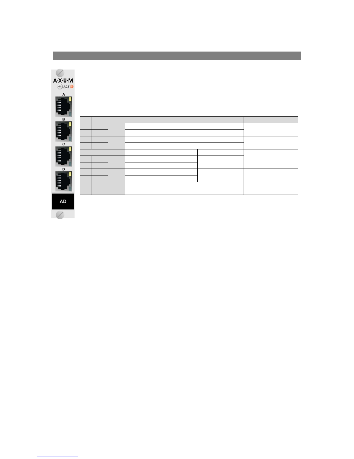
A·X·U·M User Manual Version 2.5 - 2011-01-28
AXUM from D&R - Phone: +31 294 418014 - E-Mail: info@d-r.nl - 69 -
10.2 Line input card
There are four balanced stereo line inputs available on each card.
Each RJ45 connector represents a stereo line input and two GPIO’s which can be
connected to the 19” patch panels with a shielded twisted pair (STP) cable.
For each GPIO you can choose, by way of a hardware jumper on de board, between TTL
Input/output or Photo-MOS relay output see chapter 11.3.1 GPIO TTL/Relay selection. For
software configuration see chapter 9.3 GPIO.
Table 10-2: Line input RJ45 connection
Pin
Con.
Pair
Pin name
Function
Comment
1
1A 1 +Audio 1
Left line input in-phase
Imp. 20kΩ
max. level +26dBu
2
1B
-Audio 1
Left line input out-phase
3
2A 2 +Audio 2
Right line input in-phase
Imp. 20kΩ
max. level +26dBu
6
2B
-Audio 2
Right line input out-phase
If jumper TTL-GPIO If jumper GPO
see chapter 11.3.1
5
3A 3 GPIO1a
GP-Out (TTL)
Photo MOS relay
(max 50V, 200mA)
4
3B
GPIO1b
nGP-In (TTL)
7
4A 4 GPIO2a
GP-Out (TTL)
Photo MOS relay
(max 50V, 200mA)
see chapter 11.3.1
8
4B
GPIO2b
nGP-In (TTL)
S GND S Shield GND
Audio ground and
reference for GP-In
Page 70
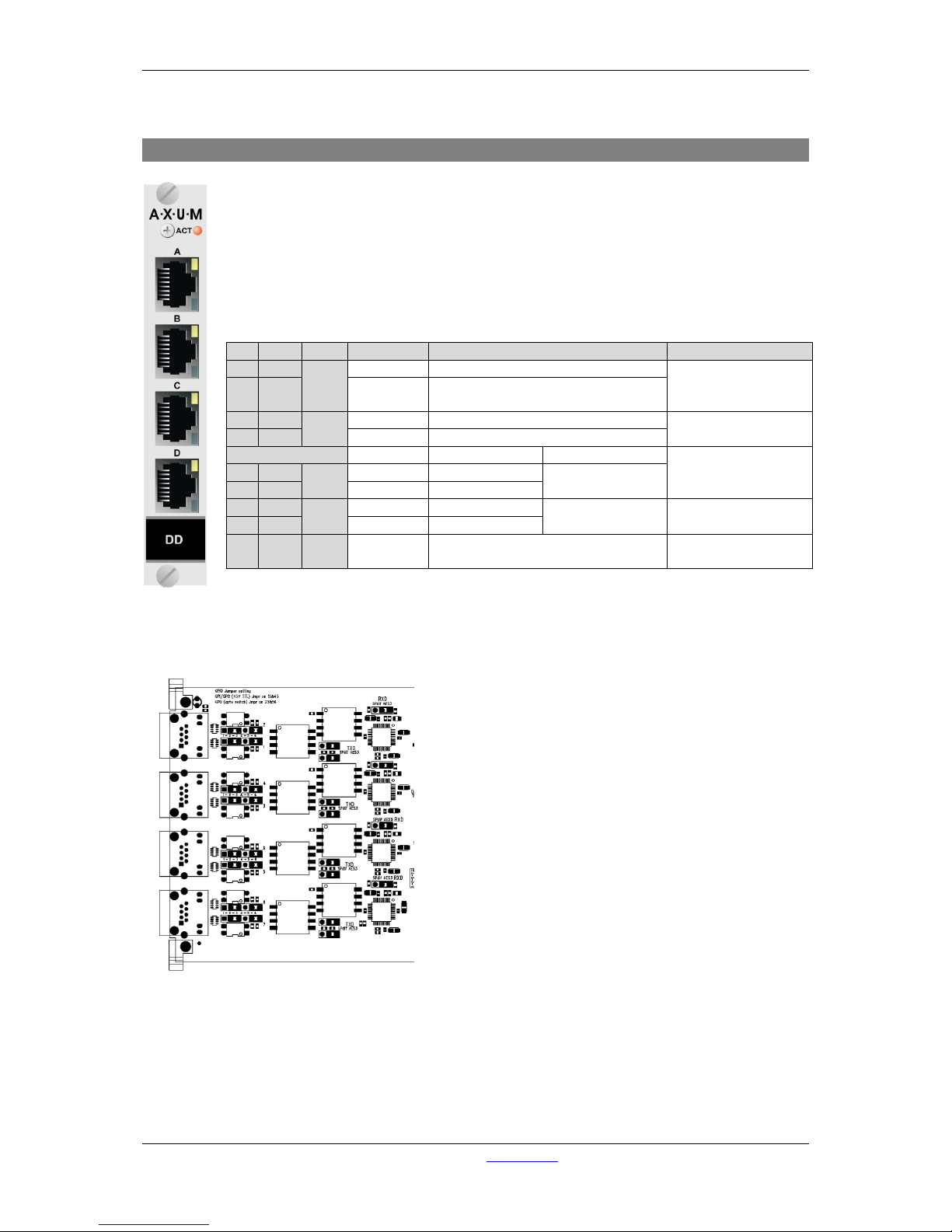
A·X·U·M User Manual Version 2.5 - 2011-01-28
AXUM from D&R - Phone: +31 294 418014 - E-Mail: info@d-r.nl - 70 -
10.3 Digital in/output card (opt ional SRC)
There are four balanced digital inputs and outputs available on each card.
Each RJ45 connector represents a stereo line input and two GPIO’s which can be
connected to the 19” patch panels with a shielded twisted pair (STP) cable.
There is also a card available with built in sample rate converters (SRC).
For each GPIO you can choose, by way of a hardware jumper on de board, between TTL
Input/output or Photo-MOS relay output see chapter 11.3.1 GPIO TTL/Relay selection. For
software configuration see chapter 9.3 GPIO.
Table 10-3: Digital input/output RJ45 connection
With jumper on the I/O card it is possible to select the impedance for S/P-DIF (75Ω) or AES-3 (110 Ω)
This figures shows the jumper location on the I/O card
Figure 46: Digital S/P-DIF or AES3 selection
Pin
Con.
Pair
Pin name
Function
Comment
1
1A 1 +Audio 1
Digital input in-phase
Imp. 110Ω/75Ω
optional SRC:
32..96kHz
2 1B -Audio 1 Digital input out-phase
3
2A 2 +Audio 2
Digital output in-phase
Imp. 110Ω/75Ω
32, 44.1, 48kHz
6
2B
-Audio 2
Digital output out-phase
If jumper TTL-GPIO If jumper GPO
see chapter 11.3.1
5
3A 3 GPIO1a
GP-Out (TTL)
Photo MOS relay
(max 50V, 200mA)
4
3B
GPIO1b
nGP-In (TTL)
7
4A 4 GPIO2a
GP-Out
(TTL)
Photo MOS relay
(max 50V, 200mA)
see chapter 11.3.1
8
4B
GPIO2b
nGP-In (TTL)
S GND S Shield GND
Audio ground and
reference for GP-In
Page 71
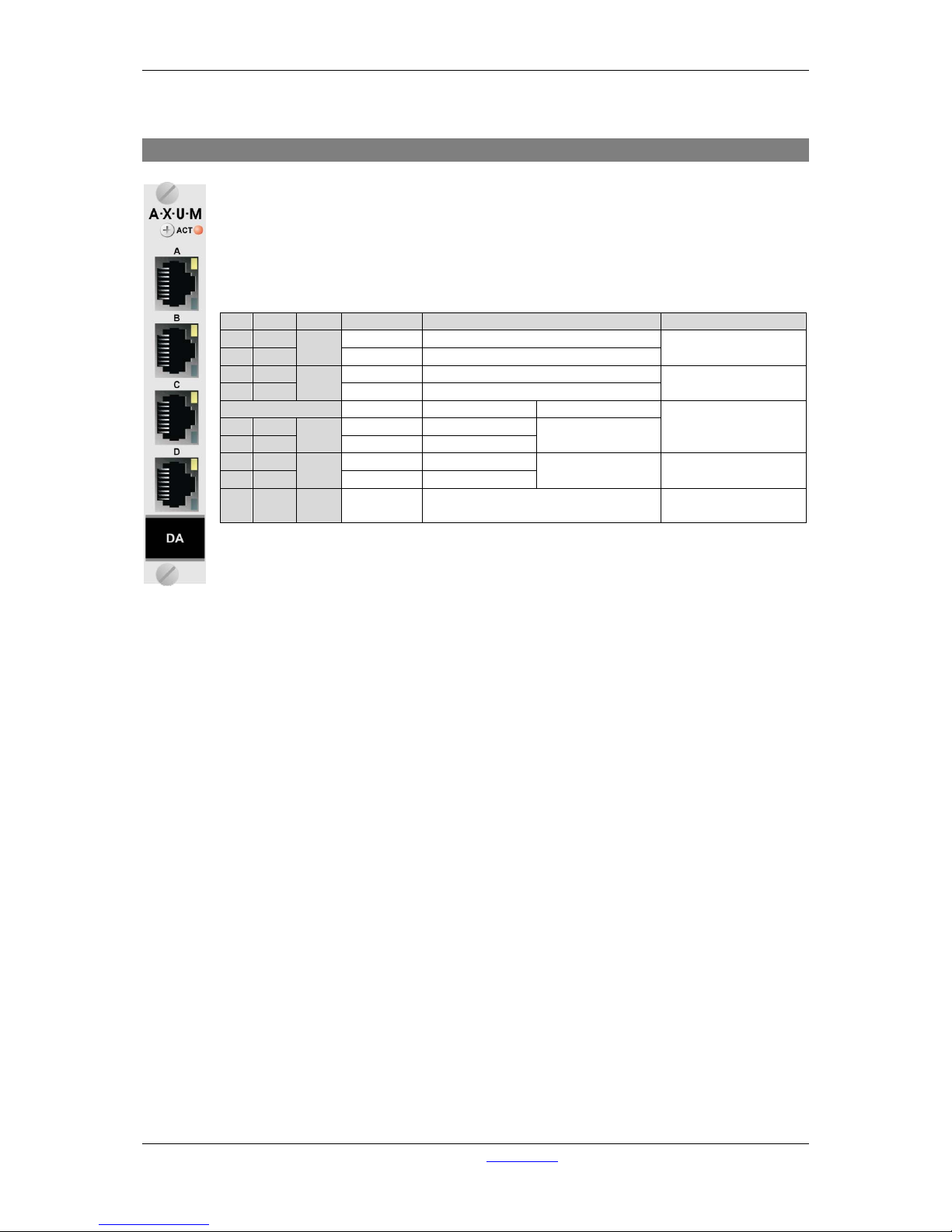
A·X·U·M User Manual Version 2.5 - 2011-01-28
AXUM from D&R - Phone: +31 294 418014 - E-Mail: info@d-r.nl - 71 -
10.4 Line output card
There are four balanced stereo line outputs available on each card.
Each RJ45 connector represents a stereo line output and two GPIO’s which can be
connected to the 19” patch panels with a shielded twisted pair (STP) cable.
For each GPIO you can choose, by way of a hardware jumper on de board, between TTL
Input/output or Photo-MOS relay output see chapter 11.3.1 GPIO TTL/Relay selection. For
software configuration see chapter 9.3 GPIO.
Table 10-4: Line output RJ45 connection
Pin
Con.
Pair
Pin name
Function
Comment
1
1A 1 +Audio 1
Left line output in-phase
Imp. 56Ω
max. level +26dBu
2
1B
-Audio 1
Left line output out-phase
3
2A 2 +Audio 2
Right line output in-phase
Imp. 56Ω
max. level +26dBu
6
2B
-Audio 2
Right line output out-phase
If jumper TTL-GPIO If jumper GPO
see chapter 11.3.1
5
3A 3 GPIO1a
GP-Out (TTL)
Photo MOS relay
(max 50V, 200mA)
4
3B
GPIO1b
nGP-In (TTL)
7
4A 4 GPIO2a
GP-Out (TTL)
Photo MOS relay
(max 50V, 200mA)
see chapter 11.3.1
8
4B
GPIO2b
nGP-In (TTL)
S GND S Shield GND
Audio ground and
reference for GP-In
Page 72
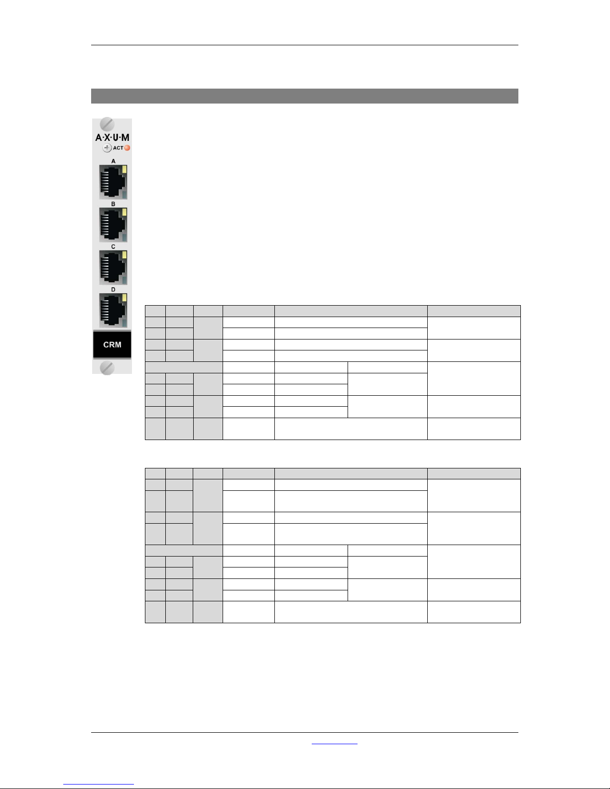
A·X·U·M User Manual Version 2.5 - 2011-01-28
AXUM from D&R - Phone: +31 294 418014 - E-Mail: info@d-r.nl - 72 -
10.5 CRM output card
There are four stereo outputs available on this card. RJ45 connector A&B represents the
CRM stereo line output. RJ45 connector C&D represents the stereo phones outputs.
Each RJ45 connector has also two GPIO’s which can be connected to the 19” patch
panels with a shielded twisted pair (STP) cable.
This stereo output card has some special functions:
- Analog level and mute functionality.
- Headphone amplifiers.
RJ45 A is stereo balanced output 1
RJ45 B is stereo balanced output 2
RJ45 C is stereo headphone output 3&4
RJ45 D is stereo headphone output 3&4
For each GPIO you can choose, by way of a hardware jumper on de board, between TTL
Input/Output or Photo-MOS relay output see chapter 11.3.1 GPIO TTL/Relay selection. For
software configuration see chapter 9.3 GPIO.
Table 10-5: CRM output RJ45 connection (A&B)
Table 10-6: Phones RJ45 connection (C&D)
Pin
Con.
Pair
Pin name
Function
Comment
1
1A 1 +Audio 1
Left line output in-phase
Imp. 56Ω
max. level +26dBu
2
1B
-Audio 1
Left line output out-phase
3
2A 2 +Audio 2
Right line output in-phase
Imp. 56Ω
max. level +26dBu
6
2B
-Audio 2
Right line output out-phase
If jumper TTL-GPIO If jumper GPO
see chapter 11.3.1
5
3A 3 GPIO1a
GP-Out (TTL)
Photo MOS relay
(max 50V, 200mA)
4
3B
GPIO1b
nGP-In (TTL)
7
4A 4 GPIO2a
GP-Out
(TTL)
Photo MOS relay
(max 50V, 200mA)
see chapter 11.3.1
8
4B
GPIO2b
nGP-In (TTL)
S GND S Shield GND
Audio ground and
reference for GP-In
Pin
Con.
Pair
Pin name
Function
Comment
1
1A 1 +Audio 1
Left phones 1 output
Imp. 5Ω
minimal phones imp.
32Ω
2 1B -Audio 1 Right phones 1 output
3
2A 2 +Audio 2
Left phones 2 output
Imp. 5Ω
minimal phones imp.
32Ω
6 2B -Audio 2 Right phones 2 output
If jumper TTL-GPIO If jumper GPO
see chapter 11.3.1
5
3A 3 GPIO1a
GP-Out (TTL)
Photo MOS relay
(max 50V, 200mA)
4
3B
GPIO1b
nGP-In (TTL)
7
4A 4 GPIO2a
GP-Out (TTL)
Photo MOS relay
(max 50V, 200mA)
see chapter 11.3.1
8
4B
GPIO2b
nGP-In (TTL)
S GND S Shield GND
Audio ground and
reference for GP-In
Page 73
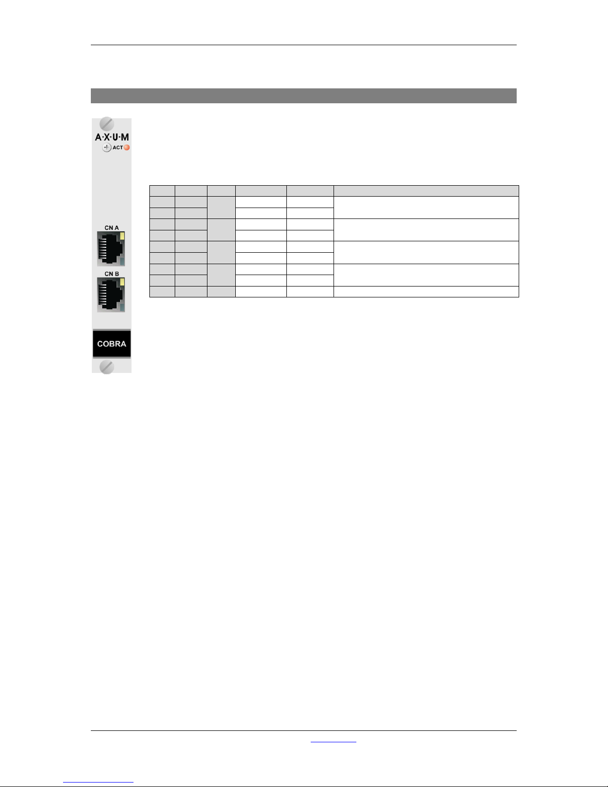
A·X·U·M User Manual Version 2.5 - 2011-01-28
AXUM from D&R - Phone: +31 294 418014 - E-Mail: info@d-r.nl - 73 -
10.6 CobraNet in/output card
This CobraNet In/output card converts the CobraNet network signals into digital audio so it
can be processed in the AXUM system’s 19” inch rack.
The CobraNet In/out card can be ordered with various channel counts, please contact your
sales contact for the available options.
Table 10-7: CobraNet RJ45 (Ethernet) connection.
Pin
Con.
Pair
Pin name
Function
Comment
1
1A 1 TX +
Ethernet
Ethernet TX 10/100BASE-T
2
1B
TX -
Ethernet
3
2A 2 RX+
Ethernet
Ethernet RX 10/100BASE-T
6
2B
RX-
Ethernet
5
3A 3 NC
4
3B
NC 7
4A 4 NC
8
4B
NC S
GND
S
Shield
GND
Ground
Page 74
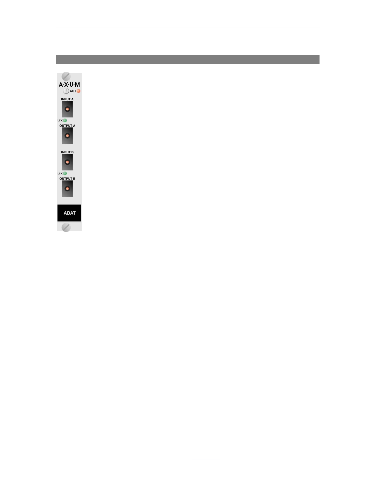
A·X·U·M User Manual Version 2.5 - 2011-01-28
AXUM from D&R - Phone: +31 294 418014 - E-Mail: info@d-r.nl - 74 -
10.7 ADAT in/output card
This ADAT In/output card converts the ADAT optical signals into digital audio which can be
received by the 19” inch rack.
The ADAT card has to run synchronous with the connected devices, allowed sample rate
frequencies are 32kHz, 44.1kHz or 48kHz.
Page 75
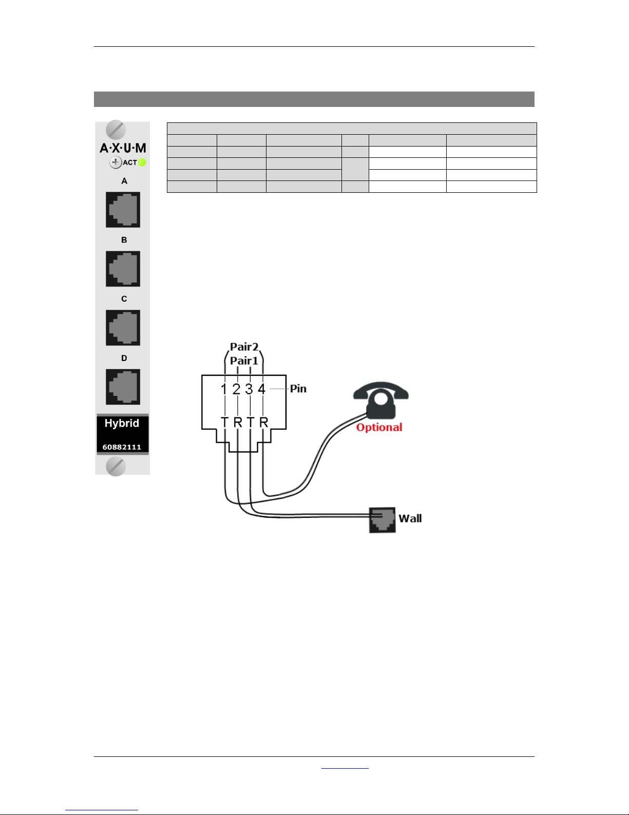
A·X·U·M User Manual Version 2.5 - 2011-01-28
AXUM from D&R - Phone: +31 294 418014 - E-Mail: info@d-r.nl - 75 -
10.8 Hybrid in/output card
Table 10-8 Hybrid Rj14 (Telephone) connection
This Hybrid In/output card converts the analog telephone signals into digital audio so it
can be processed by the 19” inch rack.
The Hybrid card
allows external callers to be connected to the AXUM. A connection can
be established via the start/stop function in the engine.
If a local phone is connected, it is possible to originate a call to a remote side. If no local
phone is present, someone at a remote site must call you.
Figure 47: Example of a single Hybrid connection
Pin connection Hybrid card.
Pin RJ14
Pin RJ11
Pin name
Pair
Function
Comment
1 R2 +
2
To Handset R +
2 1
R1 -
1
From Wall R-
3 2
T1 +
From Wall T+
4
T2 - 2 To Handset T -
Page 76
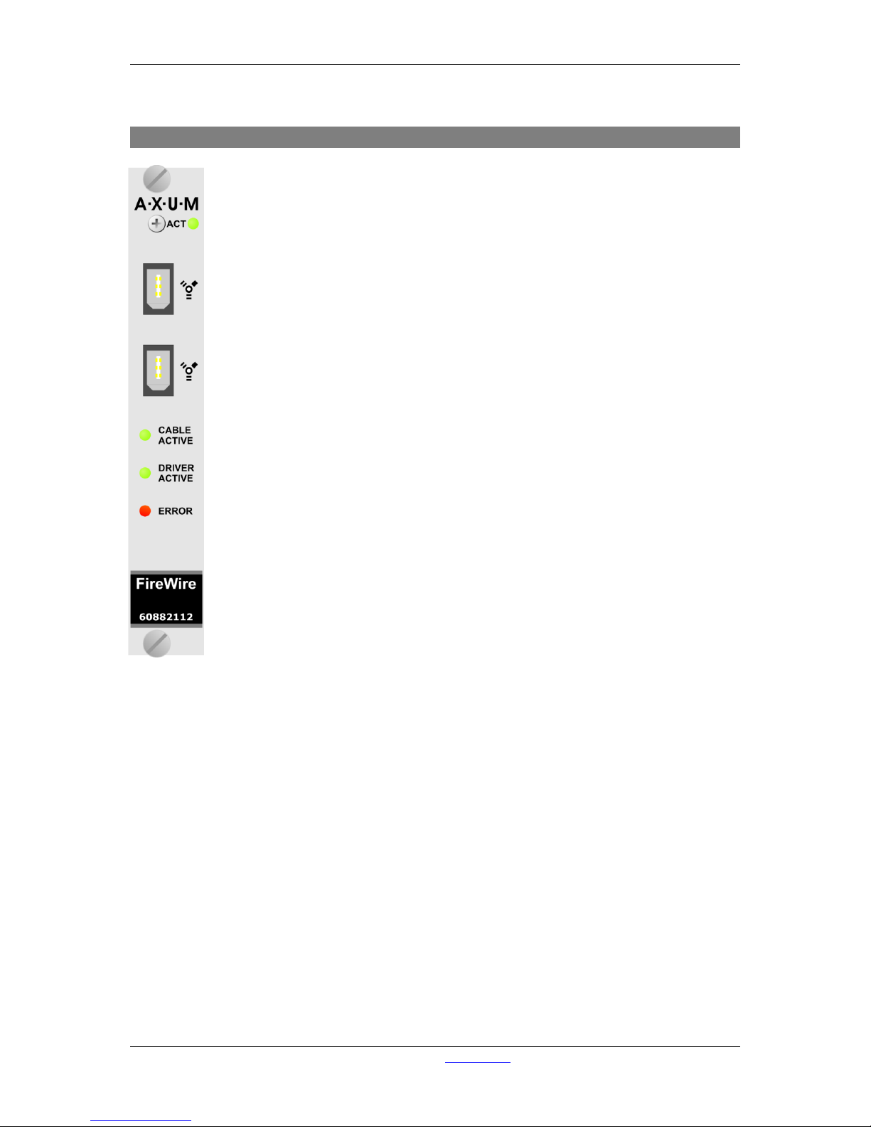
A·X·U·M User Manual Version 2.5 - 2011-01-28
AXUM from D&R - Phone: +31 294 418014 - E-Mail: info@d-r.nl - 76 -
10.9 Firewire in/output card
This Firewire In/output card converts the Firewire digital signals into digital audio which
can be processed by the 19” inch rack.
The Firewire card has to run synchronous with the connected devices, allowed sample
rate frequencies are 32kHz, 44.1kHz or 48kHz.
WDM and ASIO Drivers are available.
Via WDM driver the device is seen as a single multi-channel WDM device (8 channels).
Normally this means your card acts like a 7.1 surround card, unless your software is
capable of using the 8 channels separate.
Via ASIO driver all 16 channels are available.
Page 77
A·X·U·M User Manual Version 2.5 - 2011-01-28
AXUM from D&R - Phone: +31 294 418014 - E-Mail: info@d-r.nl - 77 -
10.10 DSP card
The DSP card adds mixing capabilities to your 19” rack. In combination with the Axum
engine, this card gives you 32 stereo processing channels to create a mixing desk.
The system may be loaded with four DSP cards, which generates a mixing console with
128 stereo channels.
The ACT(ive) LED blinks when this card functions properly.
Page 78
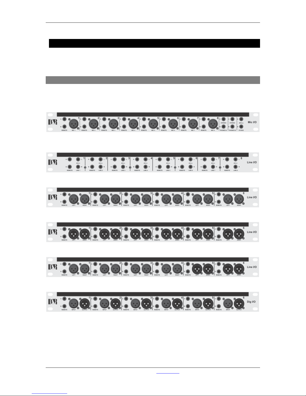
A·X·U·M User Manual Version 2.5 - 2011-01-28
AXUM from D&R - Phone: +31 294 418014 - E-Mail: info@d-r.nl - 78 -
11 Patch panels
All distribution of audio within the AXUM digital audio system is with shielded twisted pair cable.
The Breakout 19” panels, you need to connect equipment use standard audio connectors.
11.1 19” Patch panels / Breakout panels
The AXUM 19” Break out p atch pane ls c onvert t he RJ 45 Shielded conn ection t o t he ind ustr y standard
connectors such as XLR and Jack. There are various patch panels available for the AXUM for
example:
60882045, The MIC I/O with 8 MIC XLR, 16 remote jacks, 4 stereo phone jacks, 2 Line out jacks.
60882046, Line I/O jack with 16 balanced Line in/out jack and 16 remote jacks.
60882047, Line input XLR with 12 balanced Line in XLRs (female) and 12 remote jacks.
60882048, Line output XLR with 12 balanced Line out XLRs (male) and 12 remote jacks.
60882049, Line I/O XLR with 8 balanced Line in XLRs (female), 4 balanced Line out XLRs (male) and 12 remote jacks.
60882050, Dig I/O with 6 stereo digital inputs and 6 stereo digital outputs.
Figure 48: AXUM Break out Panels
Page 79
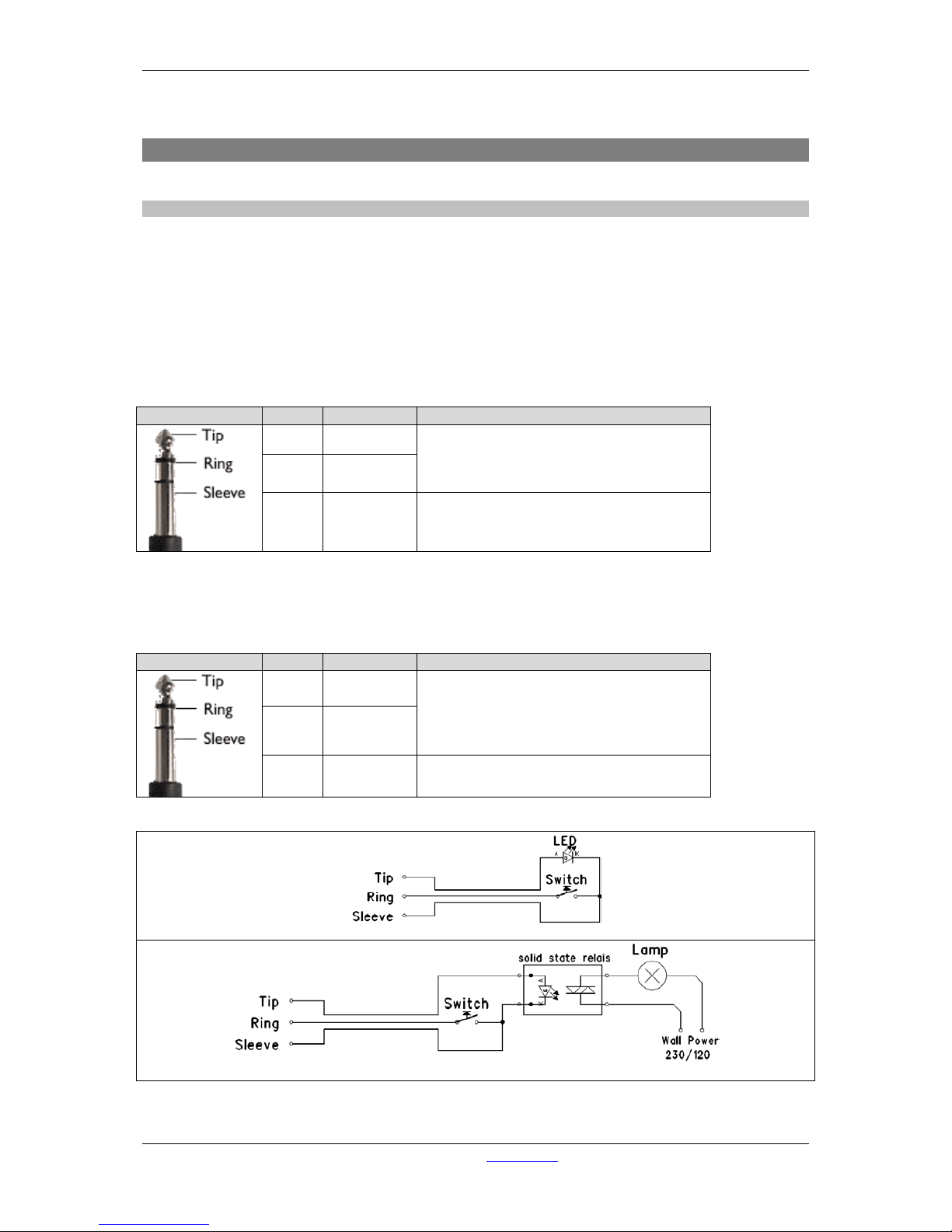
A·X·U·M User Manual Version 2.5 - 2011-01-28
AXUM from D&R - Phone: +31 294 418014 - E-Mail: info@d-r.nl - 79 -
11.2 Wiring
11.2.1 GPIO/Remote
The remote jack connects to all kinds of rem ote in-/outputs. Such as remote s tart/stop, external red
lights or cough. The function of the rem ote jack depends on the I/O card and function setup for this
GPIO. The software determines its function and where it is connected to.
! NEVER CONNECT HIGH POWER VOLTAGE (WALL POWER) TO THE REMOTE-JACK !
If the GPIO jumper setting on the Axum-Rack-Board is set for GPO the remote becomes only a
Remote-Output by a build in Solid State Relay. The relay is situated between Tip and Ring of the
remote jack.
Normally the GPIO jumper setting on the Axum-Rack-boards are set for GPO.
Jack
Name
function
Comment
Tip GP-CC
GPIO Jumper 23 & 56:
Photo MOS relay (max 50V, 200mA)
Ring GP-NO
Sleeve Shield Ground
Table : GPO Patch Panel wiring
If the GPIO jumper s etting on the Axum-rack-Boar d is set for GPIO the remote becom es a RemoteOutput GPO (+5V TTL) on the T ip of the remote jack and a Remote-Input GPI (+5V TTL interna l pullup) on the Ring. The Sleeve is Shield and the ground for the TTL signal.
Jack
Name
function
Comment
Tip GP-Output
GPIO Jumper 12 & 45:
GPO: +5V, 560R Ohm
GPI: max. +5V with 10k internal pull-up.
Ring GP-Input
Sleeve Shield Ground
Table : GPIO Patch Panel wiring
GPIO connection example for MicOn-LED and cough-switch remote.
GPIO connection example for OnAir-Lamp and TB-Switch remote.
Page 80
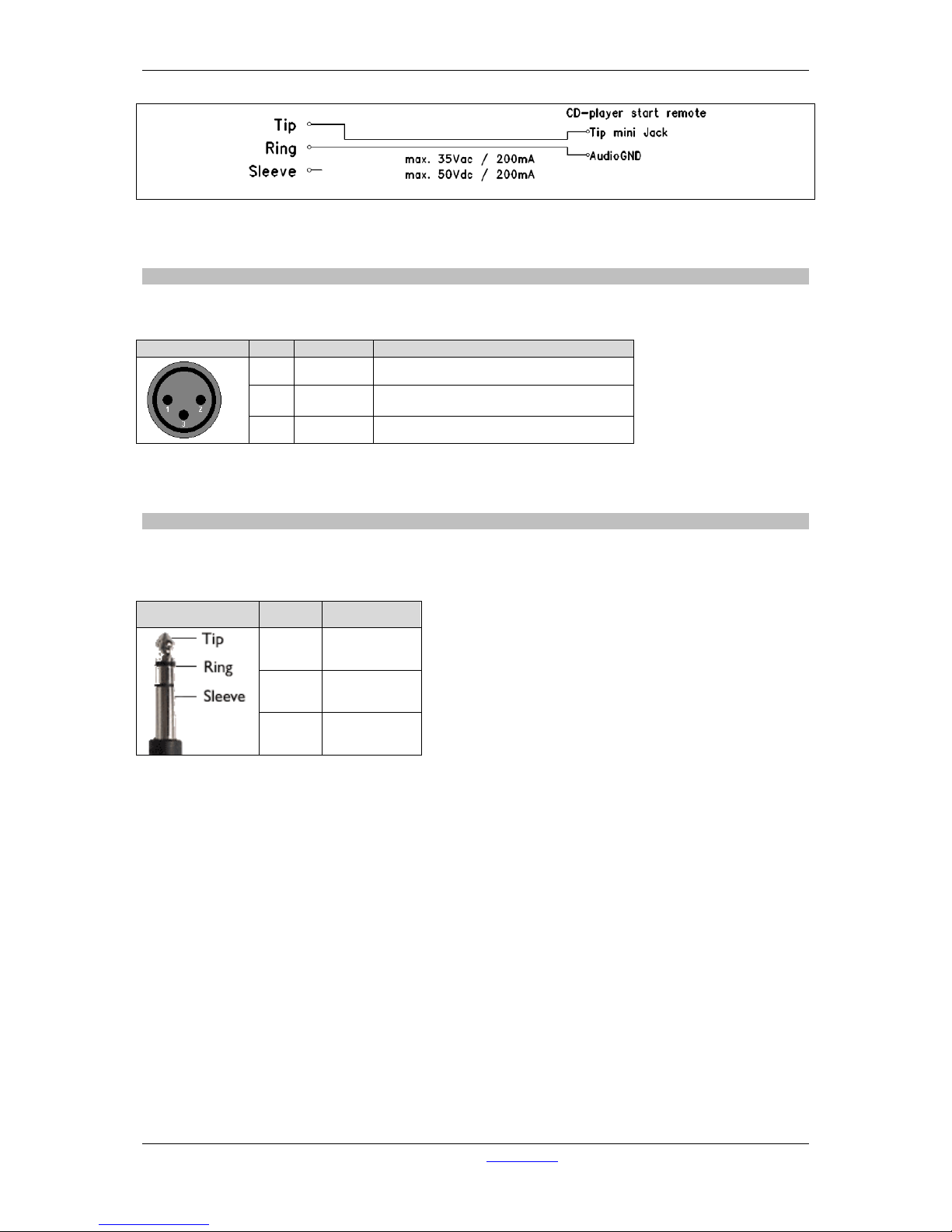
A·X·U·M User Manual Version 2.5 - 2011-01-28
AXUM from D&R - Phone: +31 294 418014 - E-Mail: info@d-r.nl - 80 -
GPO connection example for remote START Pioneer CD-player.
11.2.2 MIC
The MIC input connects m icrophones to the AXUM. The AX UM Mic Rack Module supports 48 vol ts
DC phantom power if it is switched on in the software.
Female XLR
Pin
Function
Comment
2 +Audio Audio in phase
3 –Audio Audio out phase
1 Shield Ground
Table 11-1: MIC patch panel XLR wiring
11.2.3 Phones
The Phones jacks connect headphones to the AXUM console. The PHONES-A and PHONES-B
female jack outputs all carry a stereo headphones signal. The phones connection connects to the
CRM-DA module.
Jack Name Function
Tip Audio left
Ring Audio right
Sleeve Shield
Table 11-2: Phones patch panel jack wiring
Page 81
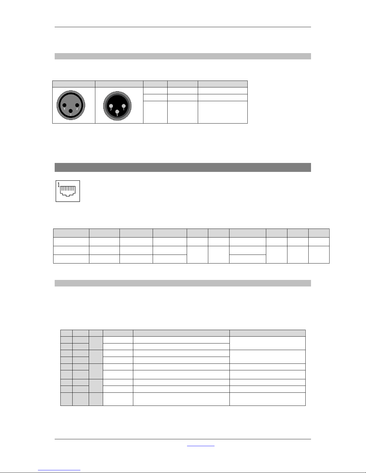
A·X·U·M User Manual Version 2.5 - 2011-01-28
AXUM from D&R - Phone: +31 294 418014 - E-Mail: info@d-r.nl - 81 -
11.2.4 Stereo line input and output
The line I/O jack patc h panel houses female jack connecters , the line I/O XLR patch panel houses
XLR type connectors (male or female).
Female XLR
Male XLR
Name
Function
Pinning
2
+Audio
Audio in phase
3
-Audio
Audio out phase
1
Shield Ground
Table 11-3: Line I/O patch panel XLR wiring
11.3 Standard RJ45 wiring
Figure 49: RJ45 Connector
Pin 1 Pin 2 Pin 3 Pin 4 Pin 5 Pin 6 Pin 7 Pin 8 Shield
RJ45 name 1A 1B 2A 3B 3A 2B 4A 4B S
Ball Left (Hot) Left (Cold) Right (Hot)
GPIO1 GPIO1
Right (Cold)
GPIO2
GPIO2 Shield
Phones Left 1 Right 1 Left 2 Right 2
Table 11-4: Standard RJ45 wiring
11.3.1 GPIO TTL/Relay selection
Each RJ45 connection on I/O cards handles audio signals and GPIOs.
The GPIO pins can be configured to work as:
• TTL in and out
this is selected by GPIO1 jumpers in the place 12 and GPIO2 jumpers in place 45. These
jumpers are located on the I/O cards, close to the RJ45 connectors.
Table 11-5: RJ45 pinning in GPIO-TLL mode
Pin
Con.
Pair
Pin name
Function
Comment
1
1A 1 +Audio 1
Left audio input or output in-phase
Imp. 2k Ohm
max. level +20dBu
2
1B
-Audio 1
Left audio input or output out-phase
3
2A 2 +Audio 2
Right audio input or output in-phase
Imp. 2k Ohm
max. level +20dBu
6
2B
-Audio 2
Right audio input or output out-phase
5
3A 3 GPIO1a
GP-Out
+5V TTL out, 560R
4 3B GPIO1b GP-In +5V TTL in, 10kR int. pull-up
7
4A 4 GPIO2a
GP-Out
+5V TTL out, 560R
8
4B
GPIO2b
GP-In.
+5V TTL in, 10kR int. pull-up
S GND S Shield GND
Audio ground and reference
for GP-In
Page 82
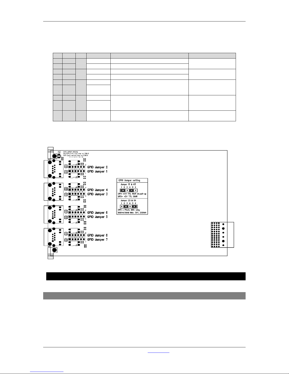
A·X·U·M User Manual Version 2.5 - 2011-01-28
AXUM from D&R - Phone: +31 294 418014 - E-Mail: info@d-r.nl - 82 -
• Relay out (no input available).
this is selected by GPIO1 jumpers in the place 23 and GPIO2 jumpers in place 56. These
jumpers are located on the I/O cards, close to the RJ45 connectors.
Table 11-6: RJ45 pinning in GPO-Relay mode
The figure shows how the jumper selection on the I/O card looks:
Figure 50: GPIO TTL/Relay jumper selection
12 Specifications AXUM digital audio system
12.1 Input/output cards
Mic inputs : Electronically balanced
: Input impedance 2k Ohm
: Input sensitivity -70dBu up to +20dBu (PAD)
: CMRR MIC inputs: 85dB @ 1kHz, maximum gain
: Phantom is switchable +48 Volts
: Optional is transformer balancing
Pin
Con.
Pair
Pin name
Function
Comment
1
1A 1 +Audio 1
Left audio input or out put in -phase
specifications
depends on I/O card
2
1B
-Audio 1
Left audio input or output out-phase
3
2A 2 +Audio 2
Right audio input or output in-phase
specifications
depends on I/O card
6
2B
-Audio 2
Right audio input or output out-phase
5
3A 3 GPIO1a
Relay, connecting a&b
Photo MOS relay
Bidirectional Max.
50V, 200mA
4 3B GPIO1b
7
4A 4 GPIO2a
Relay, connecting a&b
Photo MOS relay
Bidirectional Max.
50V, 200mA
8 4B GPIO2b
S GND S Shield GND
Audio ground and
reference for GP-In
Page 83

A·X·U·M User Manual Version 2.5 - 2011-01-28
AXUM from D&R - Phone: +31 294 418014 - E-Mail: info@d-r.nl - 83 -
Line inputs : Electronically balanced
: Input impedance 10k Ohm
: input sensitivity +6dBu, maximum input +26dBu (+/- 20dB gain range).
: CMRR Line inputs: 30dB @ 1 kHz, maximum gain
: Transformer balancing is optional on the patch panels
Line Outputs : Electronically balanced
: Output impedance 56R Ohm.
: Nominal output level +6dBu, maximum output +26dBu
: Optional is transformer balancing
Digital Inputs : AES/EBU (AES3) or S/P-DIF
: 16/20/24 bit, 32kHz to 96kHz (optional built in sample rate converter)
: Input Impedance: 110R Ohm/75R Ohm
Digital outputs: AES/EBU (AES3) or S/P-DIF.
: 16/20/24 bit, 32kHz to 48kHz
: Output level: 2 to 5 volt
: Output Impedance: 110R Ohm/75R Ohm
GPIOs : All GPO’s are by opto isolated relays able to handle a maximum of 50V at 200mA
: All GPI’s have a 5V TTL 100kOhm circuitry
: GPIO-MIC has a 5V/600Ohm LED driver circuit
12.2 DSP processing
6 Bands EQ : +/- 18 dB, 20 – 20000 Hz, 0.1Q – 10Q LPF, LShelf, Peaking, HSelf, HPF, BPF,
Notch
Dynamics : Mentioned for voice processing use, you can setup the downward expander
threshold
: AGC threshold and ratio of working of the AGC.
12.3 OVERALL
Level : 0dBu = 0.775Vrms
: 0dB internal = -20 dBFs.
Clock : Sample rate: 32 kHz, 44.1 kHz, 48 kHz, +/- 20ppm (internally
synchronized)
Frequency response : 20 - 20.000 Hz +/- 0.2dB
THD+N : <-96dBfs
Dynamic Range : typically 105dB
Crosstalk : less than -90dBr
Noise : -86dBr
Page 84

A·X·U·M User Manual Version 2.5 - 2011-01-28
AXUM from D&R - Phone: +31 294 418014 - E-Mail: info@d-r.nl - 84 -
Power supply : NeutrikTM PowerConTM (delivered in the package).
: 100-240 Volt, 50/60H z (1.7A Max )
12.4 DIMENSIONS
ADD NEW 4FBP AND CRMP FRA MES
FRAME-10
Outside : 492 x 410 x 60/90mm
Drop through : 486 x 430mm
Weight : 10kg
FRAME-14
Outside : 684 x 410 x 60/90mm
Drop through : 678 x 430mm
Weight : 15kg
FRAME-18
Outside : 876 x 410 x 60/90mm
Drop through : 870 x 430mm
Weight : 20kg
FRAME-22
Outside : 1062 x 410 x 60/90mm
Drop through : 1056 x 430mm
Weight : 25kg
FRAME-26
Outside : 1260 x 410 x 60/90mm
Drop through : 1254 x 430mm
Weight : 30kg
RACK-ONE
Outside : 483 x 133 x 260mm
RACK-TWO
Outside : 483 x 266 x 260mm
Page 85

A·X·U·M User Manual Version 2.5 - 2011-01-28
AXUM from D&R - Phone: +31 294 418014 - E-Mail: info@d-r.nl - 85 -
13 List Of Figures
Figure 1: Basic system layout
................................................................................................................. 8
Figure 2: MambaNet logo
........................................................................................................................ 9
Figure 3: 12 fader control surface
......................................................................................................... 14
Figure 4: Axum web server
.................................................................................................................... 15
Figure 5: Console 1-4 configuration
...................................................................................................... 16
Figure 6: IP/Clock configuration
............................................................................................................ 17
Figure 7: Global configuration
............................................................................................................... 19
Figure 8: Buss configuration
.................................................................................................................. 20
Figure 9: Monitor buss configuration
..................................................................................................... 21
Figure 10: Source configuration
............................................................................................................ 22
Figure 11: External source conf igurat ion
............................................................................................... 24
Figure 12: Destination configur ati on
...................................................................................................... 25
Figure 13: Talkback configuration
......................................................................................................... 27
Figure 14: Processing presets
............................................................................................................... 28
Figure 15: Processing preset settings
................................................................................................... 29
Figure 16: Processing preset EQ/Dynamics settings
............................................................................ 30
Figure 17: Module assignment
.............................................................................................................. 31
Figure 18: Input module configuration
................................................................................................... 32
Figure 19: Module configuration page
................................................................................................... 33
Figure 20: Module routing preset
.......................................................................................................... 34
Figure 21: Mix/monitor buss pres ets
..................................................................................................... 37
Figure 22: Mix/monitor buss pres et settings
.......................................................................................... 38
Figure 23: Console presets
................................................................................................................... 40
Figure 24: Surface configuration
........................................................................................................... 41
Figure 25: Node object configuration (to Axum functions)
.................................................................... 42
Figure 26: Rack configuration
............................................................................................................... 43
Figure 27: Node object configuration (to Axum functions)
.................................................................... 44
Figure 28: Source pool configuration .................................................................................................... 45
Figure 29: Preset pool configuration
..................................................................................................... 46
Figure 30: User configuration
................................................................................................................ 47
Figure 31: Service menu
....................................................................................................................... 49
Figure 32: MambaNet node overview
................................................................................................... 50
Figure 33: Node templates
.................................................................................................................... 52
Figure 34: Stored configurations
........................................................................................................... 53
Figure 35: Engine functions
................................................................................................................... 54
Figure 36: Package versions
................................................................................................................. 55
Figure 37: Change passwor d
................................................................................................................ 56
Figure 38: Console website
................................................................................................................... 57
Figure 39: IP/Clock configur ation
.......................................................................................................... 58
Figure 40: AXUM Digital audio system 19” Rack
.................................................................................. 61
Figure 41: GPI configuration
.................................................................................................................. 65
Figure 42: GPI Active-state configuration
.............................................................................................. 65
Figure 43: GPO configuration
................................................................................................................ 66
Figure 44: GPO Time configuration
....................................................................................................... 66
Figure 45: GPO Active-state configuration
............................................................................................ 67
Figure 46: Digital S/P-DIF or AES3 selection
........................................................................................ 70
Figure 47: Example of a single Hybrid connection
................................................................................ 75
Figure 48: AXUM Break out Panels
...................................................................................................... 78
Figure 49: RJ45 Connector
................................................................................................................... 81
Figure 50: GPIO TTL/Relay jumper selection
....................................................................................... 82
Figure 51: Console service menu
.......................................................................................................... 99
Figure 52: Package versions
............................................................................................................... 100
Figure 53: Change passwor d
.............................................................................................................. 101
Figure 54: Logo upload
........................................................................................................................ 102
Page 86

A·X·U·M User Manual Version 2.5 - 2011-01-28
AXUM from D&R - Phone: +31 294 418014 - E-Mail: info@d-r.nl - 86 -
14 List Of Tabl e s
Table 9-1: Frame clock input BNC
........................................................................................................ 63
Table 9-2: Frame clock output BNC
...................................................................................................... 63
Table 9-3: VGA 15p D-S ub c onnec tor
................................................................................................... 63
Table 9-4: Keyboard & Mouse mini DIN connector
............................................................................... 63
Table 9-5: USB connector (2x)
.............................................................................................................. 63
Table 9-6: RS232 9pin SUB-D connector
............................................................................................. 64
Table 9-7: Ethernet RJ45 connection
.................................................................................................... 64
Table 10-1: MIC RJ45 connection
......................................................................................................... 68
Table 10-2: Line input RJ45 connection
................................................................................................ 69
Table 10-3: Digital input/output RJ45 connection
................................................................................. 70
Table 10-4: Line output RJ45 connection
.............................................................................................. 71
Table 10-5: CRM output RJ45 connection (A&B)
.................................................................................. 72
Table 10-6: Phones RJ45 connection (C&D)
........................................................................................ 72
Table 10-7: CobraNet RJ45 (Ethernet) connection.
.............................................................................. 73
Table 10-8 Hybrid Rj14 (Telephone) connection
.................................................................................. 75
Table 11-1: MIC patch panel XLR wiring
............................................................................................... 80
Table 11-2: Phones patch panel jack wiring
.......................................................................................... 80
Table 11-3: Line I/O patch panel XLR wiring
......................................................................................... 81
Table 11-4: Standard RJ45 wiring
......................................................................................................... 81
Table 11-5: RJ45 pinning in GPIO-TLL mode
....................................................................................... 81
Table 11-6: RJ45 pinning in GPO-Relay mode
..................................................................................... 82
Page 87

A·X·U·M User Manual Version 2.5 - 2011-01-28
AXUM from D&R - Phone: +31 294 418014 - E-Mail: info@d-r.nl - 87 -
15 Declaration Of Conformity
DECLARATION OF CO N FORMI TY
Manufacturers Name: D&R Electronica Weesp B.V.
Manufacturers Address: Rijnkade 15B
1382 GS Weesp
The Netherlands
Declares that the product
AXUM digital audio system
conforms to the following product specifi cations:
EMC: NEN-EN 55103-1 1995
NEN-EN 55103-2 1995
NEN-EN 55013-1 1994
Supplementary Information:
The product herewith complies with the requirements of the EMC Directive 89/336/EEC (1989) as
amended by the CE Marking Directive 93/68/EEC (1993).
D&R Electronica Weesp B.V.
Rijnkade 15 B
1382 GS WEESP
The Netherlands
President of Engineering
Page 88

A·X·U·M User Manual Version 2.5 - 2011-01-28
AXUM from D&R - Phone: +31 294 418014 - E-Mail: info@d-r.nl - 88 -
16 Product Safety
This product is been m anufactured with the highest standards and is double-checked in our quality
control department for reliability in the "HIGH VOLTAGE" section.
• Never remove any panels, or open this equip ment.
CAUTION
• No user serviceable parts inside.
• Equipment power supply must be grounded at all times.
• Only use this product as described, in user manual or brochure.
• Do not operate this equipment in high humidi ty or expose it to water or other liquids.
• Check the AC power supply cable to assure secure contact.
• Have your equipment checked yearly by a qualified dealer service center.
• Hazardous electrical shock can be avoided by carefully following the above rules.
Voltage and current cause an electrical shock. In practice the higher the voltage the higher the
current will be and the higher the shock. However, there is another thing to consider and that is
resistance. When the resistance in Ohms is high between two poles, th e cu rrent will be low and
visa versa. All three of t hese; voltage, current and resistance are important in determining the
effect of an electrical shock.
PLEASE READ THE FOLLOWING INFORMATION VERY CAREFULLY
The severity of a shock is caused by the amount of current flowing through a person.
A person can feel a shock because the muscles in a body respond to electric current. Current
can also be fatal when it causes the chest muscles to contract and stop breathing.
At what potential is current dangerous? Well the first feeling of current is a tingle at 0.001 Amp
of current. The current between 0.1 Amp and 0.2 Amp is fatal.
Imagine that your hom e fuses o f 16 Amp can han dle 200 t imes mo re curren t than is necessa ry
to kill. How does resistan ce aff ect the sh ock a p er son feels? A typical res ist ance betw een your
two hands "dry" condition could be well over 100,000 Ohm. But if your body is transpiring
extensively your body resistance is lowered by more than 50%. This is a situation in which
current can easily flow.
Always earth all your equipment by the grounding pin in your main plug. Proper wiring and
isolation input/output transform ers should only cure hum loops.
Always replace fuses with the same type and rating after the equipment has been turned off
and unplugged. If the fuse blows again you have an equipment failure. Do not use it again and
return it to your dealer for repair.
And last but not least be careful not to touch a person being shocked as you, yourself could
also be shocked. Once removed from the shock, have someone send for medical help
immediately!
Always keep the above-mentioned information in
mind when using electrically powered equipment.
Page 89

A·X·U·M User Manual Version 2.5 - 2011-01-28
AXUM from D&R - Phone: +31 294 418014 - E-Mail: info@d-r.nl - 89 -
17 Disclaimer
Due to a policy of continuous product improvement, D&R Electronica Weesp B.V. reserves the right to
change specifications, appearance and performance without prior notice.
Since the use of this information and the conditions by which the products are used are beyond the
control of D&R Electronica W eesp B.V., it is the obligat ion of the owner and/ or the equ ipment operator
to determine the correct and safe selection, settings and conditions of use of the equipment and
products.
To the extent that the law permits, any liability which may be incurred as a result of the use or future
use of a product manufactured or sold by D&R Electronica Weesp B.V. is limited to the cost of
repairing or replacing the failing product or component at the discretion of D&R Electronica Weesp
B.V. Either within or outside of warranty periods.
This does not extend to any loss or damage caused because of misuse or failure of the equipment or
products.
D&R Electronica Weesp B.V. shall not in any event be liable for economic lost of profits including
without limitation any incidental or consequential damage, expenses or other damages arising out of
the use or inability to use the product and/or software even if D&R Electronica Weesp B.V. has been
advised of the possibility of such a damage or for any claim by another party.
You agree to indemnify, hold harmless, and defend D&R Electronica Weesp B.V., its parent, and their
licensors, suppliers, officers, directors, employees, agents, affiliates, subsidiaries (collectively
"Indemnified Parties") from and against any and all liability incurred by or made against the
Indemnified Parties in connection with any claim arising from or related to your use.
Page 90

A·X·U·M User Manual Version 2.5 - 2011-01-28
AXUM from D&R - Phone: +31 294 418014 - E-Mail: info@d-r.nl - 90 -
18 Appendix A - Network design for AXUM
The platform AXUM design is according to the OSI-Model and makes use of protocols on different
levels. It is important to understand the philosophy on the different levels in networking and the way
the AXUM implemented this.
With this knowledge, you can make an advanced network setup within your studio(s) give you
possibilities for:
- Remote configuration
- Remote service
- Connecting multiple AXUM racks to internet.
- Secure working within office-networks.
18.1 Network levels
Most of the people are aware of IP addresses. IP stands for ‘Internet Protocol’ and is in the OSI-Model
called a ‘level 3’ protocol. In smaller office-networks, you normally only have to care about this ‘level 3’
(so IP).
The LAN connections (Local Area Network) normally use the Ethernet technology. Where the Ethernet
is called a ‘level 2’ protocol.
For your understanding ‘level 1’ is the physical cable like CAT5e (often called RJ45-cable or Ethernetcable).
An example how these ‘levels’ are used in an office network is your connection to the Internet:
- Your LAN connections are Ethernet
- Your WAN connection is DSL or GPRS/HDSPA
The fact is that the ‘level 3’ IP can be send on LAN and WAN, but the ‘level 2’ Ethernet is only
available in the local area.
18.2 AXUM Network implementation
The AXUM system communication, where you have to think of fader, knob data etc. is based on the
protocol MambaNet. MambaNet may run over other protocols and this can be L2 and L3 protocols.
Two examples of a valid AXUM solution:
18.2.1 MambaNet example 1
- MambaNet over layer 2 (Ethernet)
Is used for the Axum internal communication, where you have to think of fader, knob data etc.
etc.
- Configuration over layer 3 (IP)
Is used for the Axum configuration and service access.
This makes sense because then the AXUM internal communication is independent of any IP address
assignment and will always work independent on the IP-configuration. Second, the configuration is
based on IP so with a good network design you can access configuration and service functionality
over Internet.
Because layer 2 is a package switched solution this gives the restriction you can only use one AXUM
rack in the Ethernet network. The next example can be used in a multi-rack network setup.
Page 91
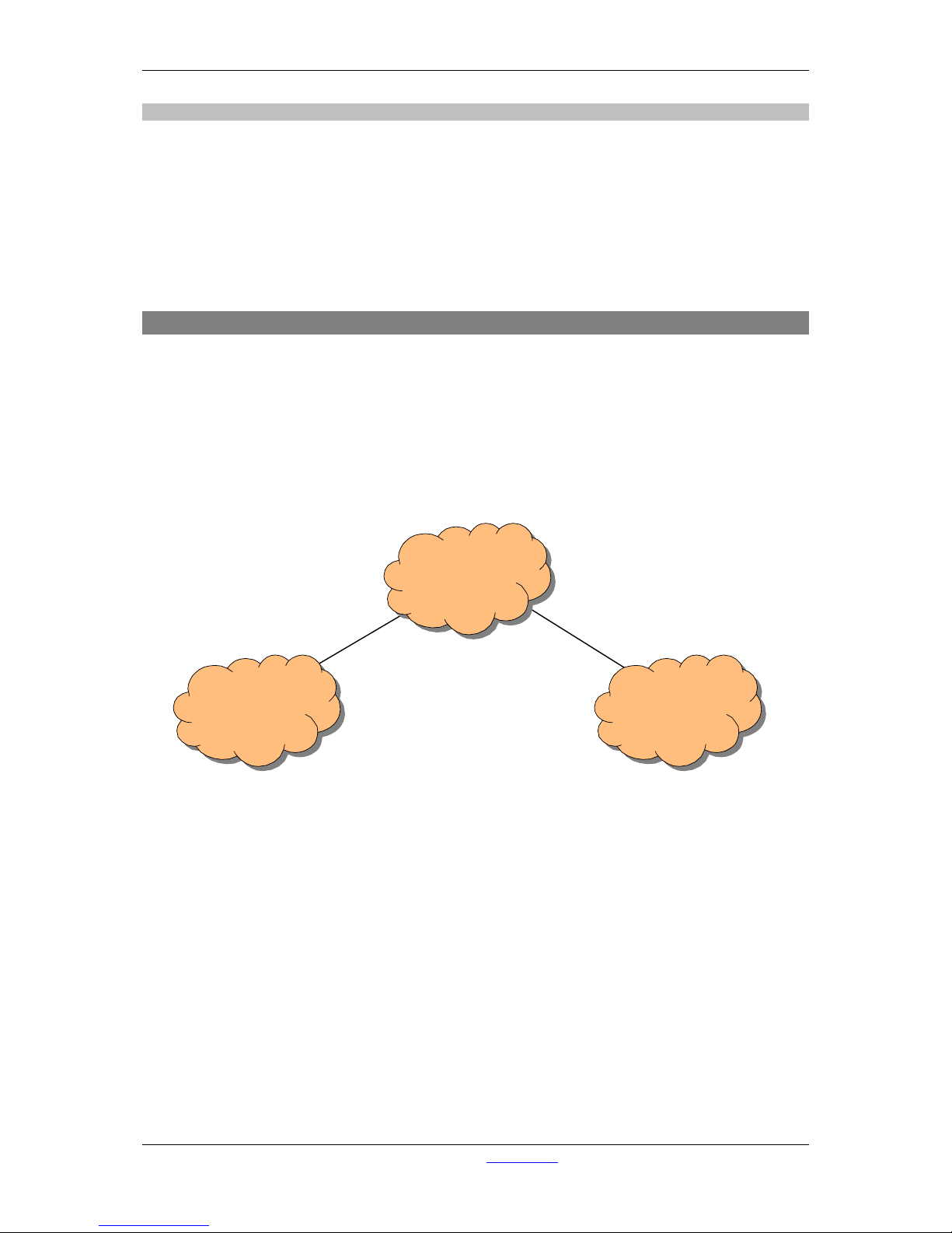
A·X·U·M User Manual Version 2.5 - 2011-01-28
AXUM from D&R - Phone: +31 294 418014 - E-Mail: info@d-r.nl - 91 -
18.2.2 MambaNet example 2
- MambaNet over layer 3(UDP or TCP)
Is used for the Axum internal communication, where you have to think of fader, knob data etc.
etc.
- Configuration over layer 3 (IP)
Is used for the Axum configuration and service access.
The MambaNet over UDP (and TCP) is connection oriented. With the destination IP address you
determine to which rack this surface hooks up.
18.3 Network design (MambaNet over Layer 2)
An AXUM system require to have an own LAN (layer 2) to work without risk of interference with office
networks and or other AXUM systems. The most basic way of describing this is:
“Each Axum system requires its own Ethernet switch”.
As you can understand this means there is no connection (so communication possible) between the
separate LANs. This creates the problem you cannot access the console(s) from a single internet
connection or from your office network. To overcome this problem you have to design the network with
a separation on ‘level 2’ (Ethernet) but a connection over ‘level 3’ (IP) must be possible.
Most simple example on such separation is:
Here you see two LAN networks, both connected to internet. With correct IP-addressing Office 1 and 2
can reach each other using the IP protocol. However, there will be no interference between Office 1
and 2 on Ethernet. In fact, you have to create the same network level-structure in your studio for
correct function.
Internet
Office 1
Ethernet
Office 2
Ethernet
DSL
(only IP)
DSL
(only IP)
Page 92
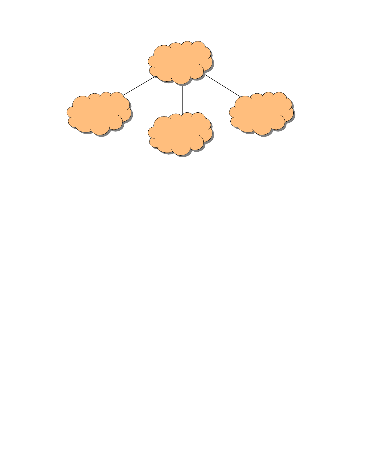
A·X·U·M User Manual Version 2.5 - 2011-01-28
AXUM from D&R - Phone: +31 294 418014 - E-Mail: info@d-r.nl - 92 -
In the next chapters we show you some solutions how to implement this structure. Because these
structures are well known in network-technologies there are also several different solutions where you
can pick the most interesting/efficient for you.
ONLY IP
AXUM 1
LAN
AXUM 2
LAN
OFFICE
LAN
Page 93
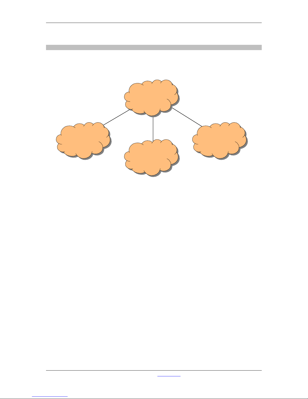
A·X·U·M User Manual Version 2.5 - 2011-01-28
AXUM from D&R - Phone: +31 294 418014 - E-Mail: info@d-r.nl - 93 -
18.3.1 Practical solution 1: Physical separated switches and IP router
If you give the AXUMs and OFFICE networks their own physical Ethernet switch, you ofcourse have
good ‘level 2’ (Ethernet) separation. If you additional hook up an IP router to the Ethernet switches it is
possible to make IP routes between the different networks, without ‘level 2’ interference.
IP ROUTER
AXUM 1
Physical
switch 1
AXUM 2
Physical
switch 3
OFFICE
Physical
switch 2
Page 94
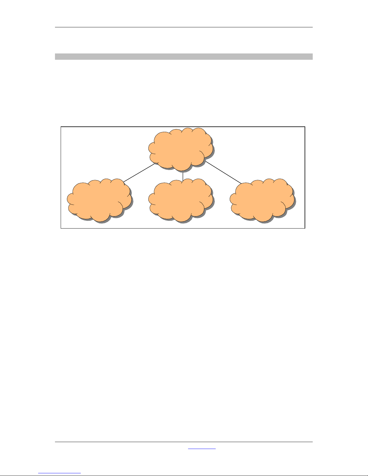
A·X·U·M User Manual Version 2.5 - 2011-01-28
AXUM from D&R - Phone: +31 294 418014 - E-Mail: info@d-r.nl - 94 -
18.3.2 Practical solution 2: single managed level 3 switch/router
When you select an level 3 managed switch with the following features:
- Port VL AN
- Inter VLAN routing (IP)
(VLAN stands for Virtual Local Area Network)
It will be possible to hook up all your network equipment to the same switch and configure the switch
so it functions equal to ‘Practical solution 1’. Therefore you have to make 3 VLANs and make correct
Inter VLAN IP routes.
INTER VLAN
IP ROUTING
AXUM 1
VLAN 1
AXUM 2
VLAN 3
OFFICE
VLAN 2
Single managed
Level 3
router/switch
Page 95
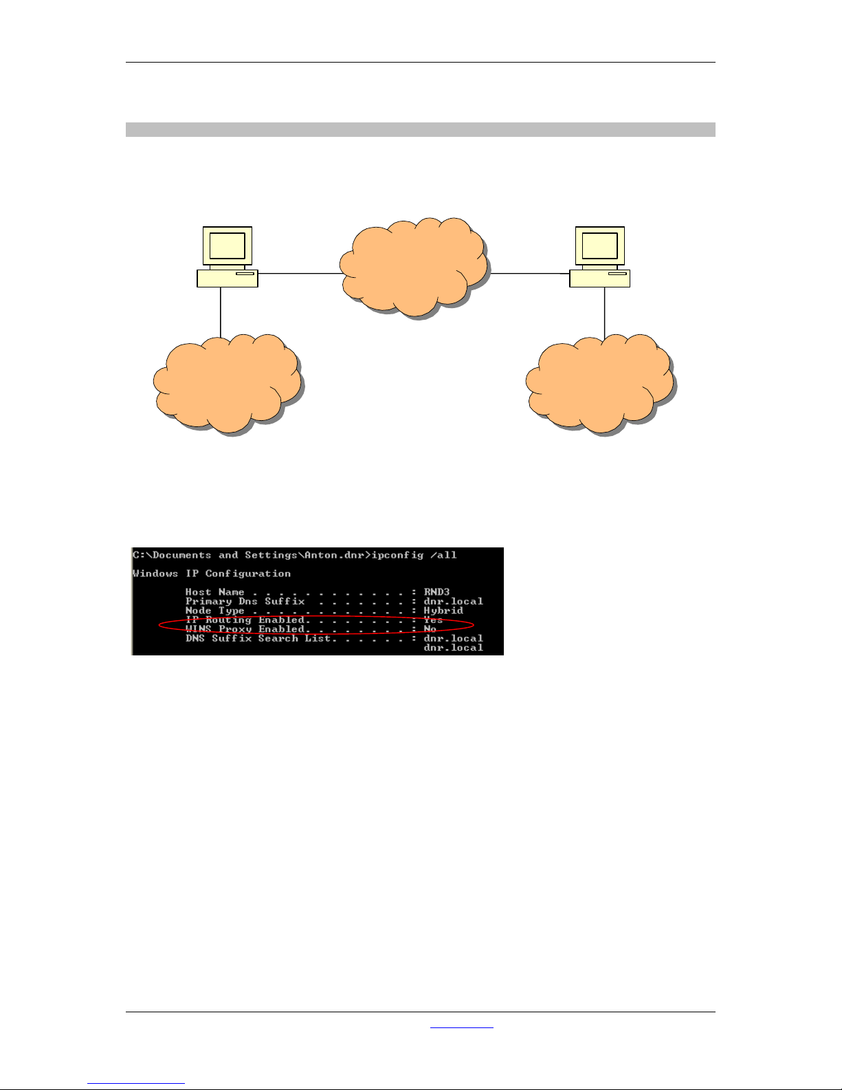
A·X·U·M User Manual Version 2.5 - 2011-01-28
AXUM from D&R - Phone: +31 294 418014 - E-Mail: info@d-r.nl - 95 -
18.3.3 Practical solution 3: Physical separated switches and PCs if IP router
It is also possible to have a PC configured to do IP routing. Of course, it is necessary to have two or
more network cards before you can make IP routing. In our example we will show an setup with two
PCs with two network card. (As you can imagine it will also be possible with one PC using three
network cards)
On a PC you can give the command: ipconfig /all
This will show if your PC is configured as a router:
If not you have to use regedit to change a parameter to ‘1’ in the registry (this requires a reboot).
HKEY_LOCAL_MACHINE\SYSTEM\CurrentControlSet\Services\Tcpip\Parameters\IPEnableRouter
AXUM 1
Physical
switch 1
AXUM 2
Physical
switch 3
OFFICE
Physical
switch 2
PC if
IP router
PC if
IP router
Page 96
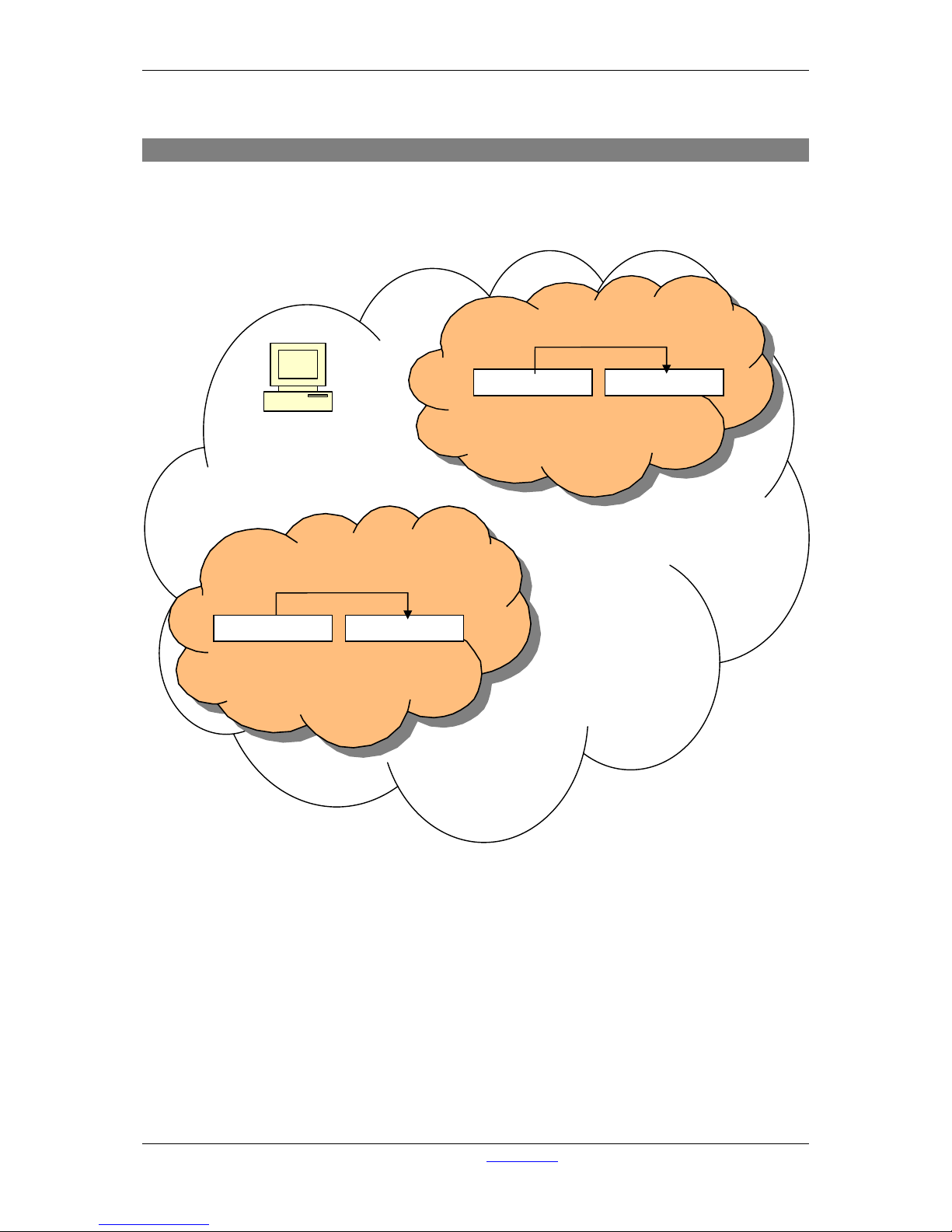
A·X·U·M User Manual Version 2.5 - 2011-01-28
AXUM from D&R - Phone: +31 294 418014 - E-Mail: info@d-r.nl - 96 -
18.4 Network design (MambaNet over Layer 3)
When using MambaNet over UDP or TCP it is possible to use multiple racks in a single network.
It is important you realize that a single surface may connect to a single rack only.
MambaNet over UDP or TCP also gives possibilities to connect to AXUM Racks over the internet; this
requires port forwarding in the router between internet and your local network.
Layer 2 network (Ethernet),
also office network.
MambaNet
cloud 1
IP :192.168.0.101
Mask : 255.255.255.0
GW : 192.168.0.1
AXUM Rack
IP :192.168.0.100
Mask : 255.255.255.0
GW : 192.168.0.1
IP :192.168.0.10
Mask : 255.255.255.0
GW : 192.168.0.1
AXUM Surface
UDP to 192.168.0.100:34848
MambaNet
cloud 2
IP :192.168.0.201
Mask : 255.255.255.0
GW : 192.168.0.1
AXUM Rack
AXUM Surface
IP :192.168.0.200
Mask : 255.255.255.0
GW : 192.168.0.1
UDP to 192.168.0.100:34848
Page 97
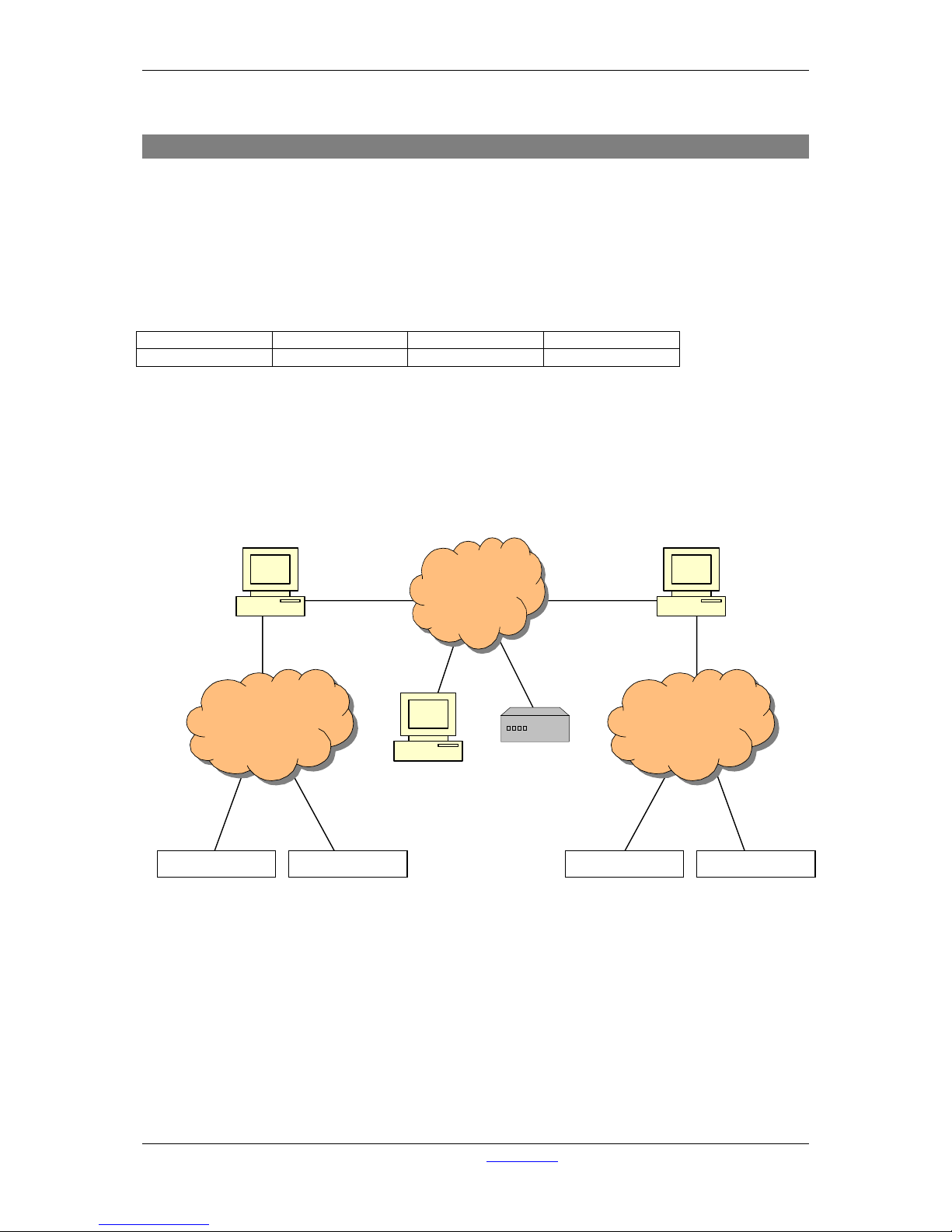
A·X·U·M User Manual Version 2.5 - 2011-01-28
AXUM from D&R - Phone: +31 294 418014 - E-Mail: info@d-r.nl - 97 -
18.5 IP subnets and IP routes
When you have made your network design, where the level 2 is separated and you IP routing is
available you need to care about correct IP addressing, subnets and routes. Altou gh your internal
AXUM configuration will function without problem. These IP addressing are necessary for:
- Configuration
- NTP time synchronization
- Remote access.
First you have to define a different subnet for each separated ‘level 2’ network. Lets say:
Network
Axum 1
Axum 2
Office
network-address
192.168.1.0/24
192.168.2.0/24
192.168.0.0/24
Where 192.168.1.0/24 also may be written as:
IP Address : 192.168.1.x
Subnetmask : 255.255.255.0
Gateway : 192.168.1.y
DNS : <IP internet DNS Server> or <IP of modem/router>
For your information we have added IP information to practical solution 3:
When you no want to reach AXUM 1 and AXUM 2 from the Example office PC it is required make
static routes. This because:
- all network addresses 192.168.1.0/24 need to be send via 192.168.0.11
- all network addresses 192.168.2.0/24 need to be send via 192.168.0.12
in the windows command line you can add permanent routes:
route -p ADD 192.168.1.0 MASK 255.255.255.0 192.168.0.11
route -p ADD 192.168.2.0 MASK 255.255.255.0 192.168.0.12
The same static routes are required if you want that the modem/router can access those subnets. You
want the modem to access the subnets in case of remote access from internet. See the modem/router
manual how to make static routes.
AXUM 1
Physical switch
1
192.168.1.0/24
AXUM 2
Physical switch
3
192.168.2.0/24
OFFICE
Physical switch
2
192.168.0.0/24
PC if
IP router
PC if
IP router
IP :192.168.1.234
Mask : 255.255.255.0
GW : 192.168.1.1
AXUM Rack AXUM Surface
IP :192.168.1.200
Mask : 255.255.255.0
GW : 192.168.1.1
AXUM Rack AXUM Surface
IP :192.168.2.200
Mask : 255.255.255.0
GW : 192.168.2.1
IP :192.168.0.20
IP :192.168.0.1
Example
office PC
Modem/router
to internet
IP :192.168.0.12
Mask : 255.255.255.0
GW : 192.168.0.1
IP :192.168.0.11
Mask : 255.255.255.0
GW : 192.168.0.1
IP :192.168.2.234
Mask : 255.255.255.0
GW : 192.168.2.1
IP :192.168.2.1
Mask : 255.255.255.0
GW : -
IP :192.168.1.1
Mask : 255.255.255.0
GW : -
Page 98

A·X·U·M User Manual Version 2.5 - 2011-01-28
AXUM from D&R - Phone: +31 294 418014 - E-Mail: info@d-r.nl - 98 -
18.6 Remote access
Now you have setup your network and IP addressing correct you have to do one last step before you
can remote access your AXUM systems. There are also different methods for remote access, for all
methods you have to check the manual of your modem/router how to setup.
1) VPN connection
Virtual Private Network is a secure way to have remote access and you can use the internal IP
numbers at your remote location.
2) Port redirection (found under NAT = Network Address Translation)
In most modems/routers you can redirect ports where you can choose the ‘Public port’ which
is accessed from internet and tell which internal IP and port it must be redirected to.
For example HTTP is normally running on port 80, and this web server is running in your local
network (IP 192.168.0.99). You also can access this webserver from remote if you make a
port redirects like:
Public port: 9080 is redirected to Private IP: 192.168.0.99, Private port: 80
Public port: 9081 is redirected to Private IP: 192.168.0.100, Private port: 80
If you are on a remote location start your webbrowser and type: <WAN-IP>:9080 you will see
the internal webbrowser 1 and with <WAN -IP>:9 081 you wil l see internal webbrowser 2.
A port redirect is less secure than VPN.
3) Open ports (found under NAT = Network Address Translation).
An open port you may give a internal private IP address, the disadvantage of an open port is
you never can reach two IP-addresses on the same port number. So one port 80 open to
webserver 1 you cannot reach webserver 2 with an open port.
An open port is less secure than port redirect, this because well known protocols are on their
own well known port numbers.
If D&R ask for remote assistance it is required you make a redirect to internal Private IP 22 of the
AXUM rack. If we want to have remote access via port redirects in the IP subnet and IP route example
as seen before we have to make the following configuration in the modem/router:
Static routes:
192.168.1.0/24 to 192.168.0.11
192.168.2.0/24 to 192.168.0.12
Port redirects:
Public port 9001 to Private IP: 192.168.1.2 00, Pr i vate Por t: 22
Public port 9002 to Private IP: 192.168.2.2 00, Pr i vate Por t: 22
Page 99
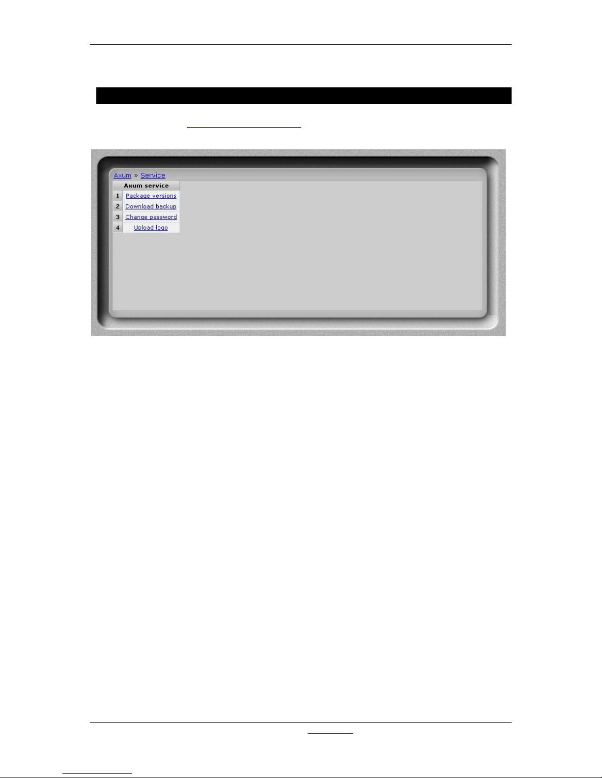
A·X·U·M User Manual Version 2.5 - 2011-01-28
AXUM from D&R - Phone: +31 294 418014 - E-Mail: info@d-r.nl - 99 -
19 Appendix B – Surface service
If you browse to the url
http://192.168.0.234/service (where 192.168.0.234 should be your local
console IP address) you have a service menu wit h give some management possibilities .
Figure 51: Console service menu
• Package versions
Shows the packages, version and build/install date.
• Download backup
Downloads a file wh ic h is a complete image of the internal flash disk.
• Change password
Here you can change the password for the webserver
• Upload logo
Here you can upload your own logo which will appear on the meter screen.
Page 100
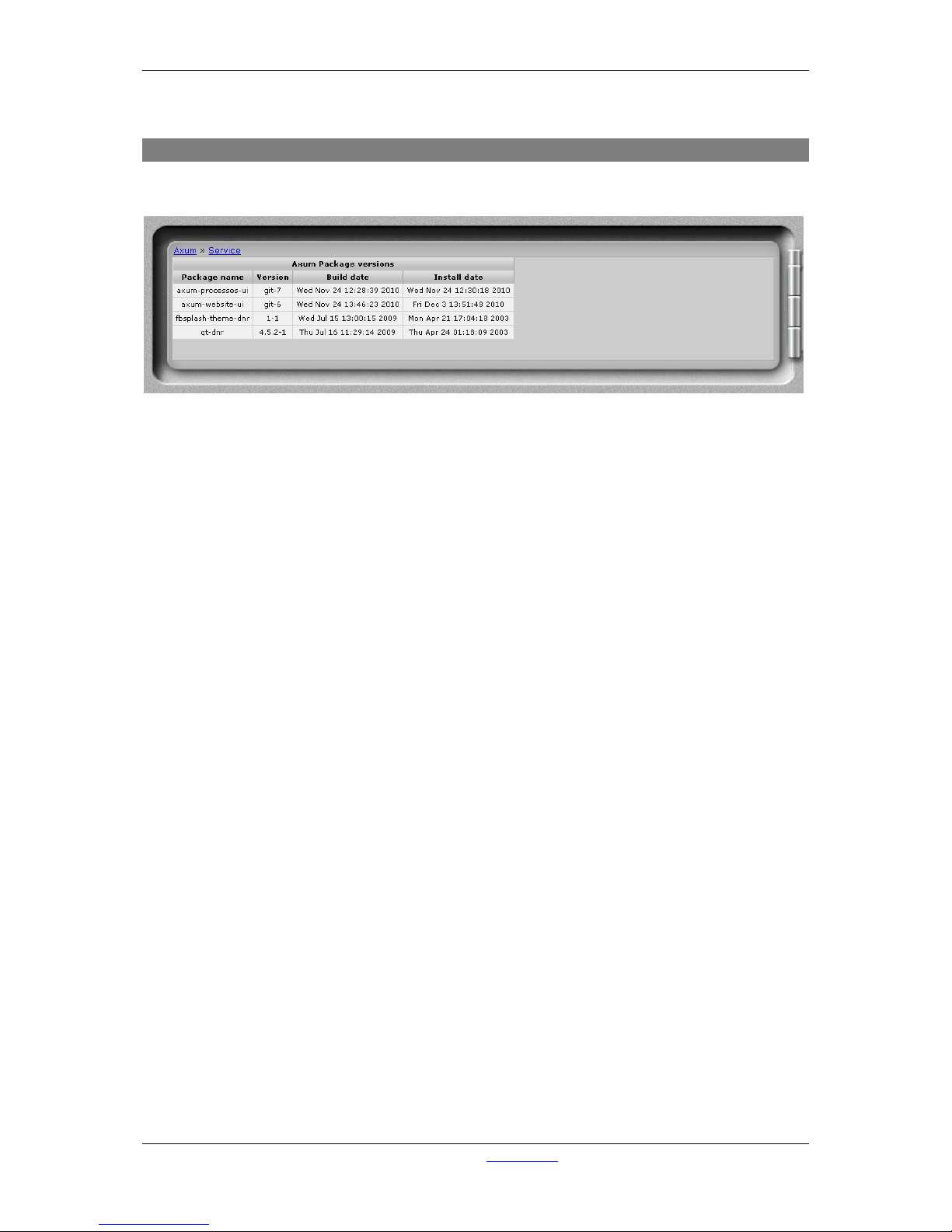
A·X·U·M User Manual Version 2.5 - 2011-01-28
AXUM from D&R - Phone: +31 294 418014 - E-Mail: info@d-r.nl - 100 -
19.1 Package versions
This page shows the installed packages with their version number, build and install date.
Figure 52: Package versions
 Loading...