

Page 1

DR STUMP GRINDER
Safety & Operating Instructions
Model: 9 HP CPSC92CHP
This manual contains information concerning proper and improper operating
procedures, warnings, maintenance, troubleshooting, assembly, and tips.
Everyone who operates this machine should read these instructions and be
thoroughly familiar with them.
Form 807-0151
03/26/04
Page 2
SECTION I - SAFETY
WARNING
Rules for Safe Operation
WARNING: To reduce the potential for any injury, comply with the
Read this owner’s manual carefully in its entirety before attempting to assemble or operate this machine. Keep
this manual in a safe place for future and regular reference and for ordering replacement parts. The operator
must familiarize themselves with the controls when the handle is swung from the front to the rear position, as
the throttle and brake controls are reversed.
Never use your stump grinder for any purpose other than chipping or cutting
stumps and roots. It is designed for this use and any other use may cause injury.
instructions in this manual. Failure to comply with the
instructions may result in personal injury.
TRAINING
INTENDED USE
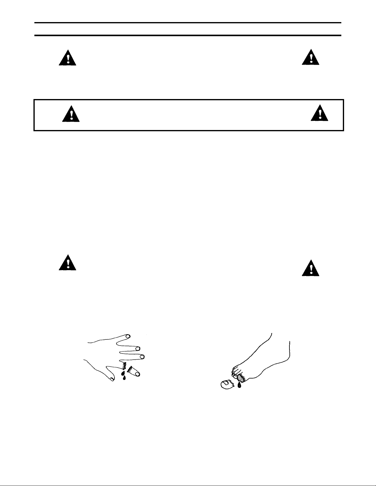
DANGER
DANGER: Rotating cutting teeth. Keep hands and feet out from under the machine when running.
DANGER: This machine can CUT and SEVER parts of your body if they are placed in the area of the
cutter head while the unit is running.
2
Page 3

Make certain that all safety labels on this equipment are kept clean and in good
condition. If you need replacement labels, please order by part number.
OPERATOR’S RESPONSIBILITY
• Never allow children to operate your stump cutter, or adults without the proper instructions. Keep children,
pets, and bystanders a minimum of 20 feet away from your work area. Flying chips can be hazardous.
• Never run this machine in an enclosed area since the exhaust from the engine contains carbon monoxide,
which is an odorless, tasteless, and deadly poisonous gas.
• Never put your hands, feet, face, or any other part of your body near the cutter head while the engine is
running.
• Never operate your stump cutter while under the influence of alcohol, drugs, or medication. A clear mind is
essential for safety.
• Never allow a person who is tired or otherwise not alert to operate this machine.
• Never operate this machine with any damaged parts or guarding removed.
3
Page 4

SAFETY WEAR
Never wear loose clothing or jewelry that can be caught by moving parts of your stump cutter and
pull you into it. Keep all clothing away from moving parts. Wear proper headgear to keep hair
away from moving parts.
Always wear safety glasses provided with your unit at all times while operating your stump
cutter. A chip could fly out and hit you in the eye. Be sure your glasses fit properly.
SAFETY OPERATING PROCEDURE
If it is necessary for any reason to inspect or repair any part of the machine, stop the machine, allow it to cool,
disconnect the spark plug wire from the spark plug and move it away from the spark plug before attempting
such inspection or repair. Whenever you operate your stump cutter, wearing safety glasses is required.
Before each use, check all three controls; brake, throttle, clutch, to be sure they are functioning properly.
The operation of any stump cutter can result in foreign objects being thrown into the eyes, which can result in
severe eye damage. Always wear the safety glasses provided with the stump cutter or eye shields before
chipping or while performing any adjustments or repairs.
OPERATE IN A SAFE ENVIRONMENT
Operate equipment only in daylight or in good artificial light.
Extreme care must be taken when operating your machine on a side hill. It could tip, or poor footing could
cause an accident. Do not operate the machine parallel to the hill. Always stand uphill from the stump.
A. Secure handle in front or rear position.
B. Do not use your machine on muddy or icy surfaces.
C. Never leave your machine unattended with the engine running.
Thoroughly inspect and clear work area of objects that might be picked up and thrown. Remove all stones,
sticks, wires, bones and other foreign objects. Beware of hidden objects located above or below ground, such
as electric wires, gas or water lines, and sprinkler systems. DO NOT BEGIN TO CHIP STUMPS unless you are
sure the area is clear.
1. Know how to turn the machine off.
2. HANDLE GASOLINE WITH CARE as it is an extremely flammable fuel.
3. Check the fuel before starting the engine. Do not fill the fuel tank indoors, while the engine is running, or
while the engine is still hot. Turn the unit off and let the engine cool for at least three minutes before
refueling. Fuel your stump cutter in a clean area to avoid getting dirt in the gas tank. Do not smoke while
refueling. Fuel tank cap must be secure at all times except during refueling. Avoid spilling gasoline or oil.
Wipe the unit clean of any spilled fuel or oil.
4. Store fuel and oil in approved containers, away from heat or open flame, and out of reach of children.
Leave 1/2-inch air space at top of fuel tank to allow for expansion of fuel.
REPAIR AND MAINTENANCE SAFETY
Never operate your stump cutter in poor mechanical condition. Periodically check that all nuts,
bolts, screws, and belts are tightened to specifications. Be sure all safety guards and shields are
in proper position. These safety devices are for your protection.
Be sure to read and follow engine owner’s manual for engine maintenance and repair.
BEFORE STARTING ENGINE, ALWAYS CHECK OIL LEVEL
4
Page 5

SECTION II - ASSEMBLY INSTRUCTIONS
PACKAGE CONTENTS
SKID POLYBAG
STUMP GRINDER OWNER’S MANUAL
HANDLE ASSEMBLY ENGINE MANUAL
POLYBAG SAFETY GLASSES
ALLEN WRENCH
4 EA – CABLE TIES
STEP 1 - UNPACKING AND CHECKING CONTENTS
1. Remove all pieces from the skid.
2. Compare all items with the list above.
3. If any parts appear missing or damaged, contact Country Home Products at 1-800-376-9637.
4. Assembly should be done on a clean and level surface.
STEP 2 - INSTALLING HANDLE SUPPORT
1. Loosen and remove the two bolts mounting the handle support (item #23, pg. 15) to the bumper straps (item
#22, pg. 15).
2. Flip the handle support to the upright position with the six adjustment holes above the bumper straps.
3. Replace and tighten the bolts through the bumper straps to the handle support that were removed in step 1
STEP 3 - INSTALLING HANDLE ASSEMBLY
The handle assembly is packed with the cables attached, so be careful not to over extend the handle away from
the stump grinder and break them loose.
1. Remove bolt and nut (items #50 & #64, pg. 15) from the pivot pin weldment (item #13, pg. 15) and pull it out
of the pivot bracket.
2. Carefully pick up the handle assembly (item #14, pg. 15) and put it in place so that the bend is down and the
handle grips are at the cutter head end (rear position). NOTE: Care needs to be taken to prevent the
cables from being torn loose, dislodged, or pinched.
3. Insert pivot pin through the first hole on the handle mount plate (item #9, pg. 15), through the lower handle
tube, and into the other hole on the handle mount plate.
4. Secure the pivot pin with the hardware you removed in step 1.
5
Page 6
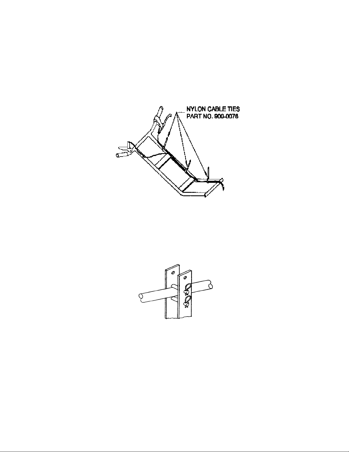
STEP 4 - SECURING THE CABLES
1. Four cable ties have been provided for fastening the cables to the handlebar after it has been installed.
Refer to figure 2 for the correct mounting points of the cable ties.
2. Attach the clutch cable in the center of the handlebar mounting pivot at point #1. Loop the cable so it
provides plenty of clearance from the belt guard and does not bind when the handle is rotated to the front
position. This attachment also keeps the cable away from the idler pulley.
3. With the handle in the rear position, opposite the cutter head, install the other cable ties at points 2, 3 and 4
(fig. 2).
4. Swing the handles from the front to the rear position while checking to make sure the cables do not bind or
become kinked.
fig. 2
STEP 5 - POSITIONING THE HANDLE
1. You can secure the handle in the front or rear position as well as adjust for height with the clevis pins (item
#78, pg. 15) and hair cotters (item #79, pg. 15) provided as shown in figure 3.
2. Note: Brake, throttle and clutch controls will be reversed when handle is switched from front to rear
position.
fig. 3
BEFORE STARTING ENGINE, ALWAYS CHECK OIL LEVEL
GREASE CUTTER HEAD BEARINGS
SEE MAINTENANCE SECTION FOR INSTRUCTION
6
Page 7

SECTION III - LUBRICATION & ENGINE START UP
FOR INFORMATION ABOUT:
1. OIL
2. FUEL
3. STARTING
4. STOPPING
5. RECOMMENDED MAINTENANCE
6. SERVICE
7. STORAGE
8. ENGINE WARRANTY INFORMATION
REFER TO THE ENGINE OWNER’S MANUAL.
THE ENGINE ON YOUR STUMP GRINDER HAS BEEN SHIPPED DRY.
BE SURE TO SERVICE THE ENGINE ACCORDING TO THE
ENGINE OWNER’S MANUAL PRIOR TO STARTING.
FAILURE TO DO SO CAN RESULT IN DAMAGE NOT WARRANTIED BY
THE ENGINE MANUFACTUROR.
WARNING: Do not fill closer than ½” from the top of the fuel tank to prevent spills and to allow for fuel
expansion. If gasoline is accidentally spilled, move the mower away from the area of the spill. Avoid creating
any source of ignition until gasoline vapors have disappeared.
CAUTION: Experience indicates that alcohol blended fuels (gasohol, ethanol, methanol) can attract moisture
which leads to separation and formation of acids during storage. Acidic gas can damage the fuel system or an
entire engine while in storage. To avoid engine problems, the fuel system should be empty before storage for
periods over 30 days. For more information, refer to the engine owner’s manual. Use fresh fuel each season.
Never use engine or carburetor cleaner products in the fuel tank or permanent damage may result.
ALWAYS CHECK OIL LEVEL PRIOR TO STARTING
THE STUMP GRINDER.
7
Page 8

SECTION IV-OPERATION
These operating instructions are designed to help you get the most out of your stump cutter.
1. It is suggested that tall stumps always be cut to near ground level with a chain saw prior to cutting with this
machine. This is a big time saver.
2. Use a mattock or other digging tool to remove dirt and stones from around the stump as deep as you intend
to cut. This is important to prolong the life of the cutter teeth. Stones that are solidly embedded in the
stump and can’t be seen will only dull the cutting teeth. The loose stones should be removed since they
can chip a tooth or be thrown by the cutter head. Your cutter head is affixed with teeth of a mining grade
tungsten carbide. It will continue to cut in spite of stones, but the fewer stones it strikes-the better.
3. Select the desired handle location for the job. Remove the hair cotter and the clevis pin (items #78, #79, pg.
15). Swing the handle (item #14, pg. 15) over to convert the stump cutter to a front or rear cutter. If the
stump is close to a building or fence, have the cutter head in front. If the stump is in the open, you may find
it is easier to chip with the cutter head in the rear. You can also change the height of the handles by
positioning the clevis pin in one of several locations. Always secure the clevis pin with the hair cotter pins.
(Figure 3 pg. 6).
NOTE: Front Position
head.
Rear Position
4. If the ground is very soft, place a sheet of plywood around the stump, especially on the sides. Pull or push
the machine up onto the stump so that about 1/3 (3” or 4”) of the cutter head is nearly touching the stump.
5. Once the machine is positioned over the stump, squeeze the brake handle to lock the wheel. The brake
locks one wheel only and allows you to make a sweeping motion with the cutter head. You can hold the
brake on with one hand or lock it in position by depressing the brake handle lock (item C, Figure 6). To
unlock the brake, simply squeeze the lever and release.
– Operator position and handle on engine end of machine, farthest from cutter
– Operator position and handle on cutter head end of machine.
fig. 6
8
Page 9

1. Move kickstand to mid-position for rear-cutting and top position for front cutting. While not in use, move the
kickstand to the down position. This keeps the cutter head off the ground, preventing damage to the cutter
teeth.
NOTE: Never adjust the kickstand while the cutter head is in motion.
1. Move throttle control to the run position. The engine will stall if you engage the cutter head while the engine
is in idle.
2. Hold operator presence handle down against the rest of handle. This will engage the cutter head. When
the operator presence handle is released, the cutter head will stop in less than two seconds. Test the unit
before operating to make sure the clutch is performing properly. If the clutch does not perform properly
discontinue use immediately.
fig. 7
1. Start to cut the stump at the extreme left (rear position) or extreme right (front position). Swing the cutter
head across the stump, cutting approximately 2” of wood at each pass. As you become more familiar with
your machine, you will be able to cut left to right and right to left. The hardness of the wood and the
sharpness of the teeth will dictate how deep and how fast you cut. See figure 8.
fig. 8
1. At the end of each pass, allow the engine to recover to full speed. Release the brake to push or pull the
cutter further into the stump, re-lock the brake and continue cutting.
2. Continue to cut across the stump until entire stump is at ground level. To cut below ground level, position
cutter head in the center of the stump and work towards the outer edges.
9
Page 10

HELPFUL HINTS
1. Chips are contained by the rubber guards and may begin to build up between the wheels.
Should there be excessive build-up, release throttle and move unit out of position and rake or
shovel away the chip build-up. A power blower or vacuum works well.
2. On larger stumps, if you continue to cut from one location, eventually a wheel may want to roll
into the hole. Before this happens, move to a different side of the stump to continue cutting.
3. It is a good idea to never operate the machine with the engine more than 30 degrees from
horizontal. This could cause engine damage due to lack of lubrication. This problem could
happen when a stump is on a steep hill. Try to cut the stump with the least amount of tilt.
WARNING
If the cutting head strikes a rock or curb and starts making an unusual noise or vibrating excessively:
1. Stop the engine immediately.
2. Disconnect the spark plug wire from the spark plug.
3. Allow the engine to cool.
4. Inspect for obvious damage.
5. Check for loose parts and tighten to assure continued safe operation.
6. Replace or repair any damaged parts.
10
Page 11

SECTION V - MAINTENANCE
LUBRICATION OF THE ENGINE
Check engine oil level regularly-WHILE THE UNIT IS IN A LEVEL POSITION. Check the oil every five hours of
operation and before each usage. Stop engine and wait several minutes before checking oil level. With engine
level:
1. Remove the oil filler plug and check oil level. It should be to the top of the fill plug.
2. If the level is low, fill to the top of the fill plug.
Change oil after the first five hours of operation and every 25 hours thereafter. Refer to the engine manual
enclosed with this unit for additional information on your engine.
AIR CLEANER
Refer to the engine manual for additional information on the air filter
1. Do not operate engine if air cleaner or cover directly over carburetor air intake is removed. Removal of
such parts could create a fire hazard.
2. Do not use flammable solutions to clean the air filter.
BEARINGS
Grease cutter head bearings after every use. Greasing should be done after unit has been washed down as
water pressure can remove grease from the bearings. The greasing process will remove any water that has
penetrated the bearing. Lubricate bearings with a #2 lithium based grease while manually rotating cutter head
until fresh clean grease is seen purging from the bearing seals.
BELT TENSION
Check belt tension frequently. This is especially important in the first one hour of use. Once the belt is “seated”
and initially stretched (approximately two hours), recheck the tension. You should check the tension each time
you use the machine. To test belt tension, push down on the belt at mid span with moderate pressure. The belt
should move approximately 1/2”.
To adjust belt tension:
1. Loosen the four motor bolts
2. Tighten or loosen the adjustment nut on the belt tensioner (item #36, pg. 15) until desired belt
tension is reached.
3. Retighten the four motor bolts.
CALIPER BRAKES
The brake is needed to prevent the machine from moving away from the stump during cutting. To adjust the
brake:
1. Loosen the locking nut on the brake handle. (Item B, fig. 9)
2. Turn the brake adjuster (Item A, fig. 9) out, away from the handle, a few turns.
3. Continue to check to see if the brake is holding.
4. When the brake “holds”, the correct adjustment is reached. Re-tighten the locking nut. (Item B, fig. 9).
fig. 9
11
Page 12

1. If correct adjustment cannot be achieved at the handle, turn the brake adjuster all the way in and adjust
brake tension at the brake caliper.
2. To adjust brake at caliper (item #26, pg. 15), loosen locking nut (Item B, fig. 10). Turn adjusting screw (Item
A, fig. 10) in until brake is holding. Retighten locking nut (Item B, fig. 10).
fig. 10
CLUTCH ADJUSTMENT
Your Stump Grinder is equipped with a brake clutch that controls the motion of the cutter head. When engaged
the clutch allows the cutter head to spin, when disengaged the clutch will stop the cutter head in under 2
seconds. It is critical that the clutch control cable be adjusted properly.
To adjust the clutch control cable:
1. Remove belt guard and disconnect clutch control cable from spring attached to clutch engagement lever
(item C, fig. 11).
2. With engagement lever fully forward measure 1 ½ “ backwards from the left hand edge of the lever and
make a mark on the clutch housing.
3. Re-connect the clutch control cable and adjust the jam nuts (item A, fig. 11) forwards or backwards as
necessary so that the lever does not pull backwards.
4. Compress the operator presence handle and check that left hand edge on the engagement lever moves
to the mark on the clutch housing.
5. Adjust cable accordingly if lever moves to the left or right of the mark.
6. If more adjustment is needed, move the cable end support (item B, fig. 11) as necessary.
Clutch cable tension should be checked periodically along with belt tension.
fig. 11
CLUTCH SERVICING
The clutch is shipped from the factory assembled and adjusted. No internal adjustment is available to the end
user. For service, return the clutch to the factory.
STORAGE
Never store your stump grinder indoors or in an enclosed, poorly ventilated area if gasoline remains in the tank.
Fumes may reach an open flame, spark or pilot light from a furnace, water heater, clothes dryer, cigarette, etc.
When not in use, your machine should be stored out of reach of children with the spark plug removed. Always
allow the engine to cool before storing of covering. For long periods of storage (over winter), please refer to the
engine owner’s manual.
12
Page 13

SECTION VI – CUTTER HEAD
The cutter head is fastened to the mounting flange on the spindle with four 3/8-16 x 1-3/4” bolts. Be sure to
check them frequently for tightness. (Figure 12)
TEETH
Your stump cutter is equipped with carbide tipped teeth. (Items 24d, 24e, 24f, pg. 15) Carbide retains its
sharpness longer, cuts faster and smoother and can withstand heat, but they will wear. Sharpen the teeth
before excessive wear or when they look dull or rounded. Check the teeth on the cutter head after each use.
Always check the 45-degree tooth first because it is the most abused being a “digger and leader”. Any cutter
tooth with less than a 10-degree relief (see fig. 15, pg. 14) will cause poor performance, smoke and burn marks.
By keeping the teeth sharp, you will prevent frustration at the job site. It only takes a few minutes to touch them
up before you go out on a job. If the unit receives heavy use, a second cutter head assembly can be purchased
as a back up while the other head is being sharpened.
fig. 12 fig. 13
FOR PROPER OPERATION:
1. Teeth should be installed according to the pattern shown in Figure 13 above.
2. Cutter head must never be run with a missing or damaged tooth.
CAUTION: Excessive vibration is usually a result of broken or missing teeth. Stop engine, disconnect spark
plug wire and inspect.
TO SHARPEN
Teeth can be removed and sharpened individually or while still attached to the cutter head.
1. Remove entire cutter head (see figure 12) by removing the four 3/8”-16 nuts and bolts.
2. To remove the teeth from the cutter head, remove the 9 cap screws using the 5/16” Allen wrench
provided.
3. Tap any of the 9 teeth with a soft hammer to “pop” the cover off the cutter body.
4. Remove the 9 teeth from their slots.
WARNING: WHEN SHARPENING TEETH, ALWAYS WEAR EYE PROTECTORS AND A
DUST MASK OR RESPIRATOR. CARBIDE DUST CAN BE DANGEROUS IF INHALED.
13
Page 14

5. Any bench-type or pedestal style grinder with a “Green wheel” (silicon carbide grinding wheel or
diamond wheel) may be used on the carbide teeth. A regular gray wheel (coarse grinding wheel) is
needed for grinding the steel relief. It is best if you can set up the grinder with a coarse wheel on one
side and “Green Wheel” on the other side.
6. Teeth may be ground free hand since precision is not important. Any variance between teeth will not be
noticed.
7. Using the “Green Wheel”, grind the end of the carbide until the edge is sharp. Avoid grinding on the
face of the carbide, which would reduce its thickness and weaken it, making it more susceptible to
cracking and chipping. (Figure 14)
fig. 14
8. As the end of the carbide is ground away, you will have to grind “relief” on the square steel shank. The
steel must be ground with the regular coarse grinding wheel and not the “Green Wheel”.
9. Although the angle is not critical, always grind the tooth so that there is enough “relief” under the
carbide edge (minimum 10 degrees). (Figure 15)
fig. 15
10. The tooth may continue to be ground until the carbide has approximately 1/4” remaining (Figure 16).
fig. 16
11. Before reinstalling the teeth, wire brush the inside of the cutter body and the cap screws. Spray with
light oil or WD40 and reassemble. Remember to reassemble teeth in the same order: 45 degree offset,
25 degree offset, and straight; repeated three times (Figure 13, pg. 13). Make sure to align the notch in
the teeth with the slot in the cutter head body so the cover plate can be assembled properly.
12. Torque cap screws on cover plate (item #24c, pg. 15) to 25 ft. lb. the first time around to insure even
pressure on the teeth. Alternate tightening screws in a crisscross pattern. Final tighten to 45 ft. lb.
13. The teeth can also be sharpened without removing them from the cutter head. Sharpen them free hand
by holding the entire head up to the grinding wheels.
14. To reassemble cutter head to drive shaft weldment:
15. Clean mating surfaces of cutter head and shaft. Spray both with light oil or WD40.
16. Reinstall cutter head using new 3/8” split lock washer and nuts
17. Pre-tighten nuts in crisscross pattern to 25 ft. lb. Final tighten to 45 ft. lb.
CAUTION: CHECK FOR LOOSE PARTS BEFORE USING YOUR STUMP GRINDER.
14
Page 15

Page 16

ITEM NO
1
2
3
4
5
6
7
8
9
10
11
12
13
14
15
16
17
18
19
20
21
22
23
24
24a
24b
24c
24d
24e
24f
24g
24h
24j
25
26
27
28
29
30
31
32
33
34
35
36
37
38
39
40
41
42
43
CPSC92CHP PARTS LIST
. PART NO. QTY. DESCRIPTION
807-0101
807-0104
807-0121
807-0122
807-0137
807-0060
807-0154
807-0109
807-0110
807-0111
807-0118
807-0119
807-0025
807-0068
807-0140
807-0141
807-0124
807-0128
807-0129
807-0130
807-0131
807-0132
807-0133
807-0070
807-0007
807-0008
090-0513
807-0001
807-0002
807-0003
090-0113
090-0228
090-0207
030-0279
807-0006
807-0005
807-0013
030-0246
807-0059
807-0134
807-0135
807-0136
909-0012
030-0399
913-0044
807-0116
807-0153
807-0037
500-0041
030-0269
030-0268
807-0004
1
1
1
1
1
1
1
1
1
2
1
1
1
1
1
1
1
1
1
1
2
2
1
1
1
1
9
3
3
3
4
4
4
2
1
1
2
2
3
1
1
1
1
1
1
1
1
1
2
1
1
1
Machine Base Weldment
Cutter Head Support Weldment
Brake Plate
Brake Cable End Mount
Axle
Wheel Spacer
Kickstand Bracket
Kick Guard
Handle Mount Plate
Adjustment Plate
Idler Bracket
Cable End Support
Pivot Pin Weldment
Handle Weldment
Clutch Plate- Clutch
Clutch Plate- Engine
Belt Guard Weldment
Inner Guard
Guard Mount- Cutter End
Guard Mount- Engine End
Bumper Tube
Bumper Strap
Handle Support
Cutter Head Assembly
Cutter Head Body
Cutter Head Cover
3/8-24 x 1” Socket Head. Cap Screw GR8
Cutter Teeth - Straight
Cutter Teeth - 25 Degree LH
Cutter Teeth - 45 Degree LH
3/8-16 x 1 3/4 HHCS GR5 PLTD
3/8 Split Lock Washer PLTD
3/8-16 Hex Nut PLTD
1 3/16” 2 Bolt Bearing
Brake Caliper
Brake Rotor
Wheel 13/5.00-6 W/1” Dia. Hub
1” Drive Shaft Bearing
Axle Locking Collar
Drive Side Guard
Engine Side Guard
Open Side Guard
Idler Sheave
Engine- 9HP B & S Intek
Belt Tensioner
Clutch Control Cable
Throttle Control
Brake Handle
Black Handle Grip 7/8” x 5”
Clutch Brake CB62S
5H740 Belt
Pulley- 5 3/4” Dia.
16
Page 17

CPSC92CHP PARTS LIST
ITEM NO
. PART NO. QTY. DESCRIPTION
44
45
46
47
48
49
50
51
52
53
54
55
56
57
58
59
60
61
62
63
64
65
66
67
68
69
70
71
72
73
74
75
76
77
78
79
80
81
82
83
84
85
86
87
88
89
90
030-0118
030-0117
090-0013
090-0066
090-0072
090-0073
090-0088
090-0089
090-0110
090-0111
709-3408
090-0119
090-0153
090-0162
090-0226
090-0232
090-0233
090-0234
090-0394
090-0438
090-0460
090-0461
090-0470
090-0503
090-0617
703-0424
807-0036
807-0057
703-0425
080-0053
020-0001
709-3409
090-0497
807-0146
807-0056
100-0015
807-0035
090-0024-3
900-0074
090-0418
807-0009
500-0031
807-0156
090-0248
090-0400
706-1539
030-0286
1
2
1
9
12
4
3
3
4
4
1
1
1
2
1
2
27
4
3
4
31
12
2
35
1
2
1
1
1
3
2
1
1
1
2
2
1
7
4
2
1
1
1
2
2
2
1
Bushing 1 3/16”
Retaining Ring 1 3/16
1/4-20 x 1 3/4 HHCS GR5 PLTD
5/16-18 x 3/4 HHCS GR5 PLTD
5/16-18 x 2 HHCS GR5 PLTD
5/16-18 x 2 1/4 HHCS GR5 PLTD
5/16-18 x 1 HHCS GR5 PLTD
5/16-18 x 1 1/4 HHCS GR5 PLTD
3/8-16 X 1 HHCS GR5 PLTD
3/8-16 X 1 1/4 HHCS GR5 PLTD
Pin
3/8-16 X 2 1/4 HHCS GR5 PLTD
7/16-20 X 1 1/4 HHCS GR8 PLTD
#10-32 X 3/8 Slotted Self Tapping Screw
7/16 Internal Tooth Lock Washer PLTD
1/4 USS Flat Washer PLTD
5/16 USS Flat Washer PLTD
3/8 USS Flat Washer PLTD
5/16 Split Lock Washer
5/16-18 J-nut Plain
5/16-18 Nylon Insert Locknut PLTD
3/8-16 Nylon Insert Locknut PLTD
1/4-20 Nylon Insert Locknut PLTD
5/16-18 Self Tapping Screw
1/4-20 x 2 1/2 HHCS GR5 PLTD
1/4 SQ x 2” Key
Full Clevis
Clevis Pin 1/4 Dia. x 7/8 Long PLTD
Spring- Le-041D-7MW
5/16-18 x 5/16 Socket Set Screw w/patch
3/8-16 x 5/8 Socket Set Screw
Spring
3/8” E-Ring
Operator Presence Handle Weldment
Clevis Pin 5/16 Dia. x 2 Long PLTD
3/32 Hair Spring Cotter PLTD
Brake Cable Assembly
1.500 OD x 1.015 ID x 0.075 THK Shim
Cable Tie 1/8 x 5 1/2
5/16-18 Whiz Lock Nut PLTD
Drive Shaft Weldment
1/4 SQ x 1” Key
Leg Weldment
5/16-24 x 3/4 HHCS GR5 PLTD
#10-32 X 1 1/4 Slotted Head Machine Screw
#10-32 Kep Nut PLTD
Clutch Control Spring
17
Page 18

NOTES
18
Page 19

NOTES
19
Page 20

NOTES
COUNTRY HOME PRODUCTS
Meigs Road, P.O. Box 25, Vergennes, Vermont 05491
1(800)DR-OWNER (376-9637)
2001 CHP, Inc. 157721 CODE #31045X
03/26/04
20
 Loading...