

Page 1
®
`
DR
SAFETY & OPERATING INSTRUCTIONS
42" LAWN MOWER DECK
DR Power Equipment
Serial No.
Order No.
Read and understand this manual and all instructions before operating the DR 42" LAWN MOWER DECK.
Original Language
Toll-free phone: 1-800-DR-OWNER (376-9637)
Fax: 1-802-877-1213
Website: www.DRpower.com
Page 2

Table of Contents
y
Chapter 1: General Safety Rules.............................................................................................................................................. 3
Chapter 2: Setting Up The DR 42" LAWN MOWER DECK .................................................................................................... 5
Chapter 3: Operating DR 42" LAWN MOWER DECK ............................................................................................................ 8
Chapter 4: Maintaining The DR 42" LAWN MOWER DECK.................................................................................................. 10
Chapter 5: Troubleshooting.................................................................................................................................................... 14
Chapter 6: Parts Lists, Schematic Diagrams And Warranty .................................................................................................. 16
Conventions used in this manual
This indicates a hazardous situation, which, if not avoided, could result in death or serious injury.
This indicates a hazardous situation, which, if not avoided, could result in minor or moderate injury.
This information is important in the proper use of your machine. Failure to follow this instruction could result in damage
to
our machine or property.
Serial Number and Order Number
A Serial Number is used to identify your machine and is located on the Serial Number Label on your machine. An Order Number
is used to check and maintain your order history and is located on the upper left portion of your packing slip. For your
convenience and ready reference, enter the Serial Number and Order Number in the space provided on the front cover of this
manual.
Additional Information and Potential Changes
DR Power Equipment reserves the right to discontinue, change, and improve its products at any time without notice or obligation
to the purchaser. The descriptions and specifications contained in this manual were in effect at printing. Equipment described
within this manual may be optional. Some illustrations may not be applicable to your machine.
2 DR
®
42" LAWN MOWER DECK
Page 3
Chapter 1: General Safety Rules
#
#
#
• Read this Safety & Operating Instructions Manual before you use the DR 42" LAWN MOWER DECK. Become familiar with
the operation and service recommendations to ensure the best performance from your machine.
• Before you use the DR 42" LAWN MOWER DECK refer to and follow your DR
Operating Instructions Manual for Field and Brush Mower specific Warnings and Cautions.
If you have any questions or need assistance, please contact us at www.DRpower.com or call toll-free 1-800-DR-OWNER (376-
9637) and one of our Technical Support Representatives will be happy to help you.
®
FIELD and BRUSH MOWER Safety and
Labels
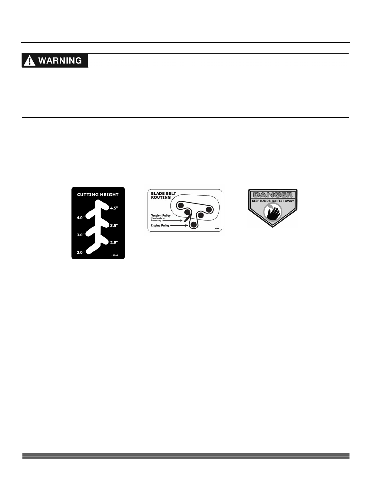
Your DR 42" LAWN MOWER DECK carries prominent labels as reminders for its proper and safe use. Shown below are copies of
all the Safety and Information labels that appear on the equipment. Take a moment to study them and make a note of their
location on your LAWN MOWER DECK as you set up and before you operate the unit. Replace damaged or missing safety and
information labels immediately.
157641
164381
136491
CONTACT US AT www.DRpower.com 3
Page 4

General Safety
Operating this DR 42" Lawn Mower Deck safely is necessary to prevent or minimize the risk of death or serious injury. Unsafe
operation can create a number of hazards for you. Always take the following precautions when operating this Lawn Mower Deck:
• This is a high-powered machine, with moving parts operating with high energy at high speeds. You must use proper clothing
and safety gear when operating this machine to prevent or minimize the risk of severe injury. This machine can cut and sever
parts of your body if they contact the Moving Blades.
• Thoroughly inspect the area in which you will be working and remove all foreign objects. Clear the area of objects such as
Rocks, Toys, Wire, Bones, Sticks, Glass etc., which could be picked up and thrown by the Blades which could damage the
machine and/or cause injury.
• Read this Safety & Operating Manual before you use the DR 42" Lawn Mower Deck. Become familiar with the operation and
service recommendations to ensure the best performance from your Lawn Mower Deck.
• Never allow people who are unfamiliar with these instructions to use the Mower. Allow only responsible individuals who are
familiar with these rules of safe operation to use your machine.
• Keep your hands and feet away from the Blades, Belts, Blade Pulleys, and concealed areas while the engine is running. Never
reach under the Deck or grab hold of any part of the Deck when the Engine is running.
• Never use the Mower with the Discharge Chute removed.
• Never, under any conditions, remove, bend, cut, fit, weld, or otherwise alter standard parts on the dr 42" Lawn Mower Deck.
This includes all Shields and Guards. Modifications to your machine could cause personal injuries and property damage and
will void your warranty.
• Your DR 42" Lawn Mower Deck is a powerful tool, not a plaything. Exercise extreme caution at all times. The design of this
machine is to cut grass. Do not use it for any other purpose.
• Be sure all Blade and Wheel controls are disengaged before attempting to start the Engine. Engage and disengage the Mower
Blades a few times to get used to it before mowing.
• If you have to stop to remove grass or debris from the underside of the Deck, always shut off the Engine, allow the Engine to
cool five (5) minutes and remove the Spark Plug Wire(s) before removing grass or debris.
• Know how to stop the Blades quickly; see page 8.
• Stop the Blades when crossing gravel drives, walks, or roads.
• Always operate the Mower from behind. Never pass or stand on the discharge (right) side or in front of machine when the
Engine is running.
• Do not pull the Mower backwards unless absolutely necessary. Look down and behind before, and while moving backwards.
• If the machine starts to make an unusual noise or vibration, immediately shut off the Engine and wait five (5) minutes for all
moving parts to come to a complete stop and cool. Disconnect the Spark Plug Wire(s). Vibration is generally a warning of
trouble. Inspect for clogging or damage. Clean and repair and/or replace damaged parts.
• Keep all Nuts and Bolts tight, especially the Blade attachment Bolts, and keep the equipment in good operating condition.
• The Mower blades are sharp and can cut. Wrap the blades or wear gloves, and use extra caution when servicing.
• Keep bystanders at least 100 feet away from your work area at all times. Objects can be thrown far from the Mower and at
great speeds. To be safe, do not operate the machine near small children or pets, and never allow children to operate the
Mower. Disengage the Blades and stop the Engine when another person or pet approaches.
• Refer to your DR
Warnings and Cautions. If you have any questions or need assistance, please contact us at www.DRpower.com or call toll-free
1-800-DR-OWNER (376-9637) and one of our Technical Support Representatives will be happy to help you.
®
FIELD and BRUSH MOWER Safety and Operating Instructions Manual for Field and Brush Mower specific
A Note to All Users
No list of warnings and cautions can be all-inclusive. If situations occur that are not covered by this manual, the operator must
apply common sense and operate this DR 42" LAWN MOWER DECK in a safe manner. Contact us at www.DRpower.com or call
1-800-DR-OWNER (376-9637) for assistance.
4 DR
®
42" LAWN MOWER DECK
Page 5
Adj
Chapter 2: Setting Up The DR 42" LAWN MOWER DECK
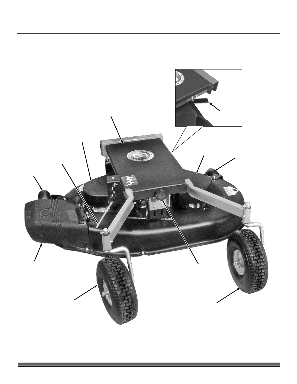
It may be helpful to familiarize yourself with the controls and features of your DR LAWN MOWER DECK as shown in Figure 1
before beginning these procedures. If you have any questions at all, please feel free to contact us at www.DRpower.com.
DR LAWN MOWER DECK Controls and Features
Main Belt
Cover
Deck Belt/Pulley
Cover (Right)
Belt Tension
Release Lever
Rear
Castor Wheel
Deflector
Cutting
Height
uster
Deck Belt/Pulley
Cover (Left)
Rear
Castor Wheel
Main Belt
Cover Knob
Front Castor
Wheels
Figure 1
CONTACT US AT www.DRpower.com 5
Front Castor
Wheels
Page 6
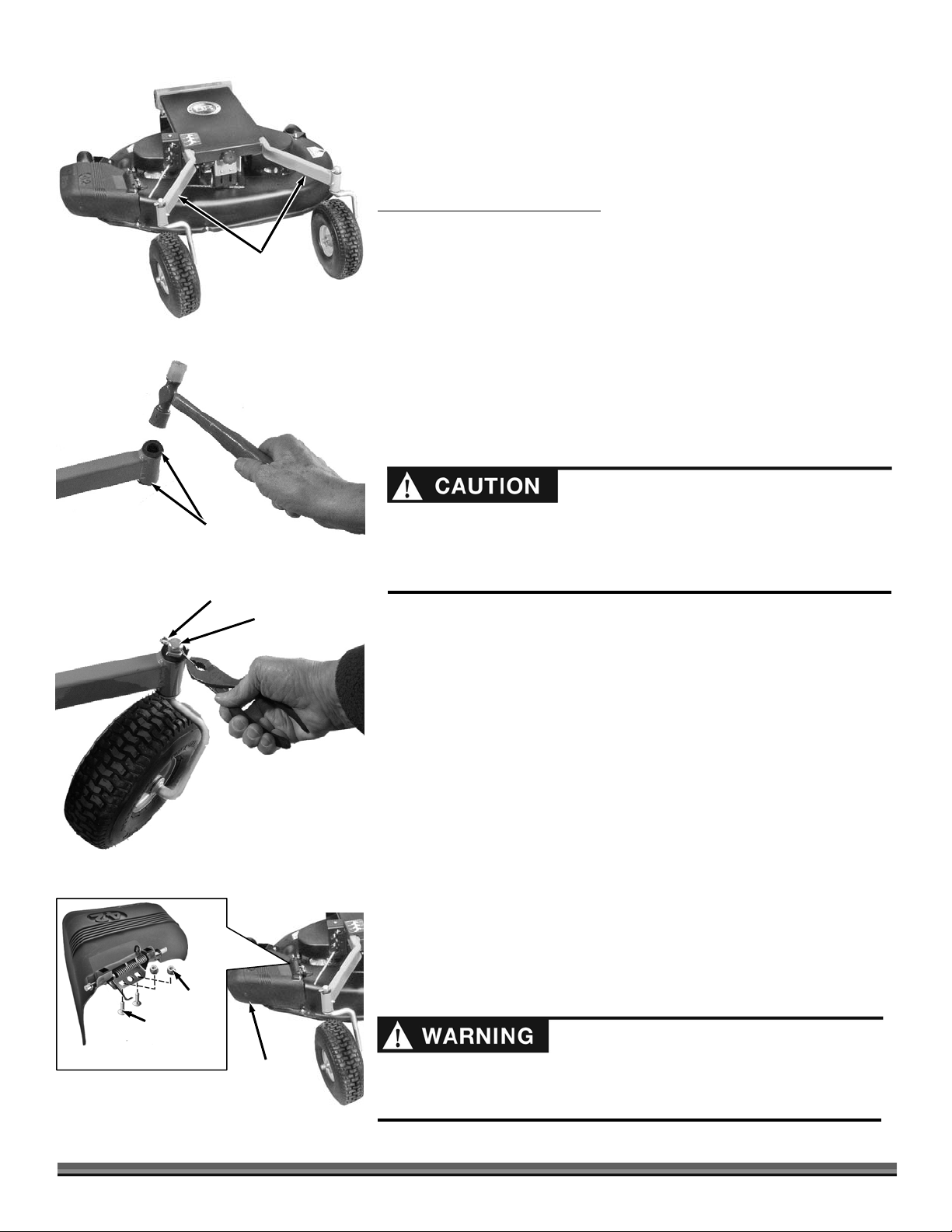
Assembling the Lawn Mower Deck
Chute
Tools Needed:
• Pliers
• Hammer
Figure 2
Figure 3
Bushings, top
and bottom
Cotter Pin
Front
Arms
Caster Wheel
Spindle
Mounting the Front Caster Wheels
NOTE: The Caster Wheels mount on the Front Arms of the Deck Frame (Figure 2).
1. Insert two black Castor Wheel Spindle Bushings (one on top and one on the
bottom) into a Front Arm of the Lawn Deck Frame. You may need to tap the
Bushings in with a Hammer (Figure 3).
2. Insert the Caster Wheel Spindle into the Bushings from the bottom(Figure
4). Push the Cotter Pin into the Hole in the Spindle as far as it will go.
3. Hold the Tire with one hand to keep the Axle from turning while bending the
legs of the Cotter Pin with Pliers. Bend the long leg first, then the shorter
leg.
4. Repeat steps 1-3 for assembly of the remaining Caster Wheel.
If you remove the Cotter Pins, replace them with new ones 1/4" in diameter
and 1-1/2" long. Repeated straightening and bending will break the Cotter
Pins at the bend, and may cause the Caster Wheels to come off during
operation causing severe damage or possible injury.
Installing the Discharge Chute
Figure 4
Figure 5
Locknut
Carriage
Bolts Under
Deck
Discharge
NOTE: If your new Lawn Mower Deck shipped separately from your DR FIELD and
BRUSH MOWER, you will need to install the Discharge Chute.
Tool Needed:
• 1/2" Wrench
1. From below, insert the two Carriage Bolts up through the holes in the Deck.
(Figure 5).
2. Set the Discharge Chute in place by fitting the Bracket over the Bolts and
install the two 5/16" Locknuts. Tighten the Nuts using a 1/2" Wrench.
Removing the Existing Attachment
Refer to your DR® Field and Brush Mower Safety and Operating Instructions
Manual for removing the Brush Deck or refer to the Attachment Users Manual
for removal of other Attachments.
Installing the Lawn Mower Deck
Wait five minutes for your DR Field and Brush Mower to cool down if it was
being used. Remove the Key and disconnect the Spark Plug Wire before
installing the Mower Deck.
6 DR
®
42" LAWN MOWER DECK
Page 7
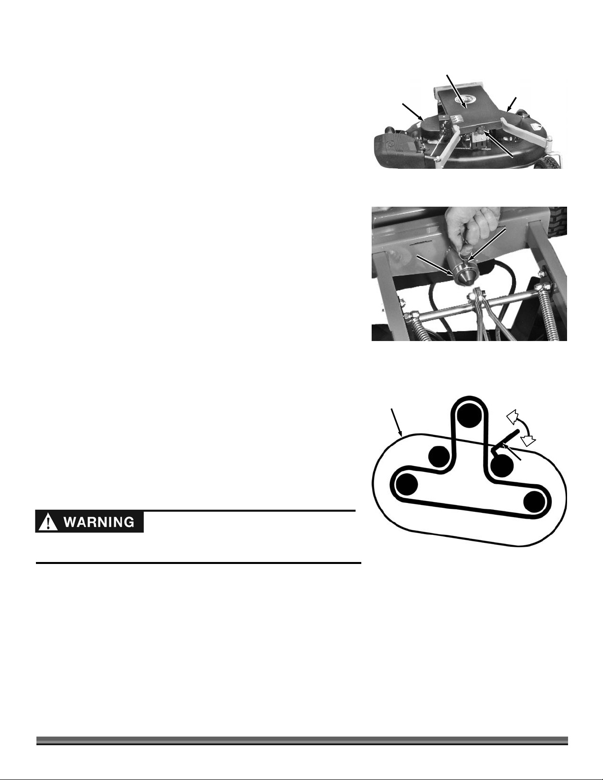
NOTE: Your Lawn Deck shipped with the Belt in place on the two Blade Drive
k
Belt
Apply
l
Pulleys. Occasionally, the Belt comes off during shipping. If this occurs,
remove the Left and Right Side Belt Covers from the Deck (Figures 6) with
a 1/2" Wrench and place the Belt back on the Pulleys.
1. Remove the Front Knob and the Main Belt Cover (Figures 6).
2. With the help of another person to steady the DR Field and Brush Mower
Power Unit, line up the Lawn Mower Deck with the Power Unit Attachment
Pin and slide the Lawn Mower Deck onto the Pin.
Right Side
Belt Cover
Main Belt
Cover
Right Side
Belt Cover
Knob
3. Attach the Collar and insert the Retaining Pin (Figure 7).
4. Mount the Belt on the Field and Brush Mower Engine Pulley. Ensure that the
Belt is routed correctly around the other Pulleys (Figure 8).
5. Push the Belt Tension Release Lever towards the center of the Deck and set
the outside of the Belt against the flat Idler Pulley that is on the Release
Lever.
Tip: Some people push the Lever with their foot.
6. Replace the Main and Side Belt Covers if you removed them.
NOTE: Be certain to replace the Side Belt Cover Hardware in the position and order
that you removed it (see “Schematic – Deck Assembly” in Chapter 6 for
reference when re-installing the covers).
Check the Tire Pressure
Tools Needed:
• Tire Pressure Gauge
• Air Compressor
1. Remove the Valve Stem Protective Cap and check the tire pressure with a
Tire Pressure Gauge.
2. Refer to the manufacturers recommended pressure is that is stamped on the
side of the Tire.
3. If the pressure is too low, add air through the Valve Stem with an air hose.
4. Replace the Valve Stem Protective Cap when finished.
Figure 6
Collar
Figure 7
Dec
Engine Pulley
BELT PATH
Retaining
Pin
Re
ease
Tension
Tension
Lever
Tension
Do not over inflate the tires. Inflate to the manufacturers recommended
pressure found on the tires.
Figure 8
CONTACT US AT www.DRpower.com 7
Page 8
Chapter 3: Operating DR 42" LAWN
For more specific information on the proper operation of the Field and Brush Mower, Refer to your DR Field and Brush Mower
Safety and Operating Instructions Manual.
MOWER DECK
Engaging the Lawn Deck Blades
5. Hold down the Operator Presence Lever (Figure 1) of your DR Field and Brush Mower.
6. Engage the Blades by pulling up on the Blade Engage/Disengage Knob.
NOTE: If you pull up on the Blade Engage/Disengage Knob before holding down the Operator Presence Lever, the engine will shut off.
Always disengage the blades of the DR 42" Lawn Mower Deck before shifting into reverse.
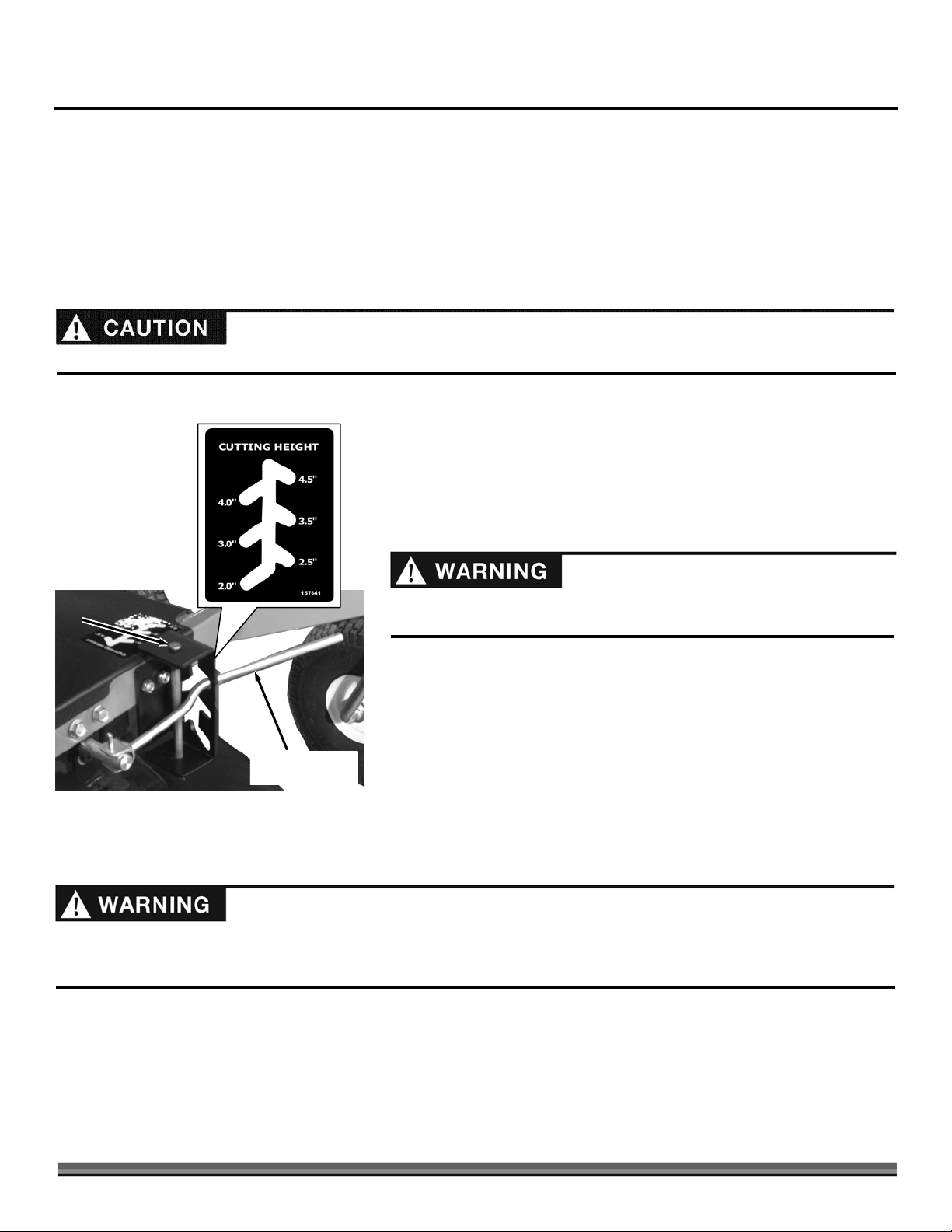
Stopping the Lawn Deck Blades
Clevis
Pin
Figure 9
Obstacle Tips
Cutting Height
Adjustment Lever
1. Disengage the Blades by pushing down on the Blade Engage/Disengage
Knob.
NOTE: Releasing the Operator Presence Lever will cause the engine to shut off but
always remember to push down on the Blade Engage/Disengage Knob before trying
to start the Engine again.
Always disengage the Blades of the DR 42 " Lawn Mower Deck before
adjusting the cutting height.
Adjusting the Cutting Height
1. To change height settings, remove the Clevis Pin and re-position the Cutting
Height Adjustment Lever. After adjusting to a new height, re-insert the
Clevis (Figure 9).
NOTE: You can adjust the cutting height of the Mower Deck in 1/2" increments.
The Clevis Pin prevents accidental dislodging of the Cutting Height Adjustment Lever
over rough terrain.
The mower engine's power can easily throw stones, sticks, and other debris at great velocity, which could cause personal injury or
property damage. Never run the machine over gravel driveways or over loose stones or mulch with the mower deck blades
spinning.
• Always check your work area before mowing and remove any debris that might tangle or damage the machine.
• If you do run into debris and the Mower Deck becomes tangled, turn off the engine and disconnect the spark plug wire(s)
before attempting to untangle the machine.
8 DR
®
42" LAWN MOWER DECK
Page 9

Slopes
When operating the DR 42" Lawn Mower Deck over uneven terrain or slopes, use extreme caution not to tip over the machine.
• Do not use the DR 42" Lawn Mower Deck on slopes greater than 20 degrees. Doing so could result in serious injury or
damage to your machine.
• If you have to mow on sloping terrain, mow across the slope, not up and down, for better control.
Tip: Locking the Differential in will improve traction, and keep the machine traveling on a straighter path. Once on level terrain,
Lock out the differential for easier turning.
• To avoid “free-wheeling”, shift into a lower gear before going down a slope. Do not shift while on a slope. Be ready to use the
brake, if necessary.
• The Mowing Deck pivots from side to side, which helps avoid scalping, and keeps the weight balanced over the drive wheels
when operating on uneven terrain.
If The Machine Becomes Obstructed
1. Disengage the Lawn Deck Blades. Do not try to free the machine from debris with the Blades engaged.
2. Try putting the machine in reverse and backing away from the obstacle.
3. Try pushing down on the Handlebars to lift the Mowing Deck over the obstacle.
• If you need to leave the operating position to clear debris from the Deck, first put the machine in "n" (neutral), turn the
Engine off, set the Brake, and disconnect the Spark Plug wire(s).
• Do not touch the exhaust areas when reaching for the Spark Plug(s), they are very hot.
Turns
• Use a low gear when turning. This will give you better control and a cleaner cut.
Reverse
• Be very careful of your footing when operating the machine in Reverse. Know what is behind you and take your time.
• Disengage the Lawn Deck Blades before shifting into Reverse. Mow in the Forward gears only, using Reverse for maneuvering.
• If you find it difficult to shift into Reverse, lightly "feather" the Clutch Lever as you put the Shift Lever into Reverse, then quickly
release the Clutch Lever.
Cutting in Wet and Heavy Grass
• Be very careful of your footing when mowing in wet conditions. Avoid steep slopes and other slippery areas.
• To achieve the best cut, mow when the grass is dry. If you have to mow when the grass is wet, use a lower, slower speed.
• We do not recommend using the optional Mulching Plate in wet and heavy grass.
CONTACT US AT www.DRpower.com 9
Page 10

Chapter 4: Maintaining The DR 42" LAWN MOWER DECK
Regular maintenance is the way to ensure the best performance and long life of your machine. Please refer to this Chapter for
maintenance procedures. The service intervals shown are maximum under normal operating conditions. Increase frequencies
under extremely dirty or dusty conditions.
Before performing any maintenance procedure or inspection, stop the engine of the Field and Brush Mower, wait five (5) minutes
to allow all parts to cool. Disconnect the spark plug wire, keeping it away from the spark plug.
Regular Maintenance Checklist
PROCEDURE BEFORE EACH USE EVERY 25 HOURS
Check General Equipment Condition
Check Blades for Sharpness
Check Tire Pressure
Check Deck Belt Tension and Condition
Lubricate Caster Wheels and Spindles
S
S
S
S
S
Lubrication
Tools and Supplies Needed:
Wheel Caster
Spindle
Figure 10
Grease
Fitting
Grease
Fitting
• Flexible Hose Grease Gun
• Lithium Grease
Before performing any maintenance procedure or inspection, stop the engine
of the Field and Brush Mower, wait five (5) minutes to allow all parts to cool.
Disconnect the spark plug wire, keeping it away from the spark plug.
NOTE: When using the Grease Gun, pump only until you feel slight resistance (1-2
pumps should do it).
1. Grease the fittings on the front Caster Wheels (Figure 10).
2. Grease the fittings on the Lawn Deck Frame where the Wheel Castor
Spindles swivel
NOTE: Perform this lubrication more often in dry and dusty environments.
Removing and Replacing the Deck Belt
Tools Needed:
• 7/16" Wrench and/or Socket
• 1/2" Wrench
• 3/16" Allen Wrench
10 DR
®
42" LAWN MOWER DECK
Before performing any maintenance procedure or inspection, stop the engine
of the Field and Brush Mower, wait five (5) minutes to allow all parts to cool.
Disconnect the spark plug wire, keeping it away from the spark plug.
Page 11

Use only a DR Belt on your machine. The Belt has been thoroughly tested and
k
Belt
Apply
l
proven for many hours of use.
1. Remove the Main Belt Cover and the two Side Belt Covers (Figure 11).
2. Push and hold the Belt Tension Release Lever towards the center of the
machine. (Figure 12).
3. Remove the Belt from the Deck Pulleys and the Engine Pulley.
4. Remove the lower Bolt on the Rear Link Plates (Figure 13) and swing the Link
Plates out of the way so the Belt clears. Remove the Belt.
5. To mount the new Belt, reverse the above procedure. The correct Belt travel
on the Pulleys is shown below.
NOTE: Be certain to replace the Side Belt Cover Hardware in the position and order
that you removed it (see “Schematic – Deck Assembly” in Chapter 6 for
reference when re-installing the covers).
Removing and Replacing the Blades
Right Side
Belt Cover
Figure 11
Dec
Main Belt
Cover
Engine Pulley
BELT PATH
Right Side
Belt Cover
Knob
ease
Re
Tension
Tension
Lever
Tension
• Before performing any maintenance procedure or inspection, stop the
engine of the Field and Brush Mower, wait five (5) minutes to allow all
parts to cool. Disconnect the spark plug wire, keeping it away from the
spark plug.
• Use caution when pushing or pulling the Wrench next to the Blade. Wear
Gloves; if the Wrench slips off the Bolt, you may be seriously injured.
Tools and Supplies needed:
• 9/16" Wrench or Socket
• Torque Wrench (optional)
• Protective Gloves
• Board to brace the Blade
1. Remove the Deck from the Field and Brush Mower and secure the Deck so
you can access the Blades.
2. Block the Blade with a piece of wood between the Blade and the Mower
Deck. (Figure 14)
NOTE: Observe the orientation of the Blade before removing in the next step.
3. Loosen the Bolt and remove the Blade Bolt, Lock Washer, and Blade Washer
by turning counter clockwise (right hand, regular thread).
4. Remove the Blade.
5. Repeat Steps 2 thru 4 for the other Blade.
Figure 12
Lower Bolt on
Rear Link Plates
Figure 13
Blade
Loosen
Wood Piece Inserted
Figure 14
CONTACT US AT www.DRpower.com 11
to Block the Blade
Page 12

Figure 15
Flange towards
Ground
Wood Piece Inserted
to Block the Blade
Main Belt
Cover
Tighten
Blade
6. Mount the new Blade (with the center flange towards the ground), Blade
Washer, Lock Washer, and Blade Bolt, in that order (
Figure 15).
7. Block the blade with the wood piece and tighten securely (Torque 30-40 ft-
lbs.).
NOTE: Be sure that you have the Blade seated completely over the small ridge in
the spindle hub before tightening the Bolt.
8. Repeat Step 6 for the other Blade.
Leveling the Lawn Mower Deck
The DR 42" LAWN MOWER DECK settings made at the factory are suitable for
most purposes, however, leveling adjustments from side to side and front to
rear can be made if desired by following the instructions below.
Before performing any maintenance procedure or inspection, stop the engine
of the Field and Brush Mower, wait five (5) minutes to allow all parts to cool.
Disconnect the spark plug wire, keeping it away from the spark plug.
NOTE: All references to left and right are from the Operator's position.
Tools needed:
Figure 16
Figure 17
Mower
Deck
Blade
Figure 18
12 DR
Rear Adjustment
Bracket (front to
rear adjustments)
Front Adjustment
Brackets (side to
side adjustments)
®
42" LAWN MOWER DECK
Knob
Measure
Here
• 1/2" Wrench
• 3/16" Allen Wrench
1. Move the machine to a level area.
2. Unscrew the Knob and remove the Main Belt Cover (Figure 16) and locate
the Adjustment Brackets (Figure 17).
Leveling the Deck Front to Rear
NOTE: Adjusting the Deck so the rear is 1/4" higher than the front will provide the
best cut.
1. Measure the distance from the ground to the bottom of the Deck Edge
Flange at the front and rear of the Deck (Figure 18).
2. Using a 3/16" Allen Wrench and a 1/2" Wrench, adjust the Deck from front
to rear as needed by moving the top and/or the bottom Bolt to a different
hole in the Rear Adjustment Bracket (Figure 19).
1/16"
Rear
Adjustment
Brackets
Deck
Figure 19
Adjustment
1/4"
Adjustment
Page 13

3. You can make further adjustments front to back by adjusting the Front
Brackets (Figure 20). Each adjacent hole will alter the deck height by 1/4"
front to back if you move both Front Brackets at the same.
Leveling the Deck Side to Side
4. Measure the distance from the ground to the bottom of the Deck Edge
Flange on the left and right sides of the Deck (Figure 18, on previous page).
5. Using a 3/16" Allen Wrench, adjust the Deck on each side as needed by
moving the Mounting Bolt to a different hole in the Front Bracket. Each
Hole in the Front Bracket will change the Deck height on that side by 1/4".
Figure 20
Deck
Front
Adjustment
Brackets
1/4"
Adjustment
CONTACT US AT www.DRpower.com 13
Page 14

Chapter 5: Troubleshooting
Most problems are easy to fix. Consult the Troubleshooting Table below for common problems and their solutions. If you
continue to experience problems, contact us at www.DRpower.com or call toll-free 1-800-DR-OWNER (376-9637) for support.
Before performing any maintenance procedure or inspection, stop the engine of the Field and Brush Mower, wait five (5) minutes
to allow all parts to cool. Disconnect the spark plug wire, keeping it away from the spark plug.
Troubleshooting Table
SYMPTOM POSSIBLE CAUSE
The Deck lacks power.
Excessive vibrations.
The Belt frays or rolls
over the Pulleys.
The cut material is not
properly discharging out
of the right side of the
Deck.
⇒ Check the Belt for wear.
⇒ Check the Blades Drive Pulleys for looseness. If you find a loose Pulley, remove the Pulley and
inspect the Pulley Hub and Blade Spindle, and replace if worn, or damaged. The design of the
Pulleys is to shear with severe loads or impact.
⇒ Check the Blades for nicks and wear. Replace or sharpen and balance the Blades if they
become dull, or have them professionally sharpened if needed. Never try to straighten a bent
Blade. Be sure to replace the Blades in the proper orientation. See page 11
⇒ The Blades may not be seated properly on the Hubs. Loosen the Blade Bolts, reset the
Blades, and tighten the Bolts. See page 11.
⇒ The Blade Spindle Bearings may be bad. Call 1 (800) DR-OWNER (376-9637) for assistance.
⇒ Check and retighten all of the fasteners as required.
⇒ A Pulley groove may have a nick in it. File off any nicks on the Pulleys.
⇒ Check the Belt for wear and hard spots.
⇒ The Belt may be stretched; replace it.
⇒ Check Flat Idler and Tensioning Pulley for alignment and wear; replace as needed.
⇒ The Discharge may be blocked. Disengage the Blades, turn off the engine, set the parking
brake, disconnect the spark plug wire(s), and then check for debris.
The Blades do not cut or
are loose.
14 DR
®
42" LAWN MOWER DECK
⇒ The Blades may not be seated properly on the Hubs. Loosen the Blade Bolts, reset the
Blades, and tighten the Bolts. See page 11.
Page 15

CONTACT US AT www.DRpower.com 15
Page 16

Chapter 6: Parts Lists, Schematic Diagrams And Warranty
Parts List - Deck Frame Assembly
NOTE: Part numbers listed are available through DR Power Equipment.
Ref# Part# Description
01 151501 Frame
02 157141 Plate, Height Adjustment
03 151561 Lever, Height Adjuster
04 123761 Bushing, .766" ID x 1.0" OD
05 150721 Bushing, 1.38" ID x 1.63" OD x 1.5" L
06 193131 Wheel, Caster, 11.4" x 4", Gray
07 143661 Knob, Handlebar, 5/16"-18
08 101891 Grease Fitting, 1/4"-28, Straight
09 110961 Pin, Roll, 3/16" x 1"
10 126851 Pin, Cotter, 3/16" x 1-1/2"
11 151511 Yoke, Caster Axle
12 160851 Cover, Guard, Main Belt, Center
13 160911 Pin, Cotter, 1/4" x 1-1/2"
14 164131 Nut, Nylon Lock, 3/8"-16, Low Profile
15 110731 Nut, Nylon Lock, 1/4"-20
16 145221 Screw, 3/8"-16 x 1-1/2"
17 151641 Plate, Anti-Torsion
18 157221 Bushing, .265" ID x .370" OD
19 114681 Bolt, 1/4"-20 x 1-1/4", HCS
20 112381 Washer, Flat, 1/4", USS
21 192461 Pin, Clevis
Safety and Information Labels
192391 Label, DR Logo, 5.75", Silver
157641 Label, Height Adjustment
16 DR
®
42" LAWN MOWER DECK
Page 17

Schematic – Deck Frame Assembly
080303
CONTACT US AT www.DRpower.com 17
Page 18

Parts List – Height Adjuster Assembly
NOTE: Part numbers listed are available through DR Power Equipment.
Ref# Part# Description
01 151551 Hanger, Lawn Deck Shaft
02 151491 Bushing, .645" ID x .75" OD x1.1" L
03 151541 Rod, Hanger, Front
04 151531 Rod, Hanger, Rear
05 157191 Plate, Link, Rear
06 151631 Plate, Link, Front
07 151591 Connector, Linkage
08 110971 Pin, Spring, 3/16" x 1-3/4"
09 151601 Screw, Shoulder, 5/16"-18
10 151921 Pin, Hitch Clip
11 157231 Spring, E, .750" OD x .093" Wire
12 110761 Nut, Nylon, Lock, 5/16"-18
13 121701 Washer, Flat, 3/8", SAE
14 157121 Bolt, 3/8"-16 x 2-1/4", HCS
15 164131 Nut, Nylon Lock, 3/8"-16, Low Profile
16 110751 Nut, Nylon Lock, 3/8"-16
17 145221 Screw, 3/8"-16 x 1-1/2"
18 DR
®
42" LAWN MOWER DECK
Page 19

Schematic – Height Adjuster Assembly
080303
CONTACT US AT www.DRpower.com 19
Page 20

Parts List – Deck Assembly
NOTE: Part numbers listed are available through DR Power Equipment.
Ref# Part# Description
01 151701 Spindle Assembly w/Hardware
02 151481 Lawn Deck w/Plate
03 151471 Lever, Idler Arm
04 151271 Pulley, Flat, Idler, 4"
05 181601 Guard, Left Belt Cover
06 181611 Guard, Right Belt Cover
07 150691 Bolt, Shoulder, 3/8"-16 x 2-1/2", HCS
08 151711 Pulley, V Belt, 6"
09 165121 Nut, Hex Lock, 9/16"-18
10 165161 Spacer, .675" ID x 1.125" OD
11 151681 Stripper
12 151691 Blade, 21", Mulching
13 165141 Washer, .385" ID x 1.390" OD
14 160281 Spacer, .39" ID x 1" OD x .785"L
15 123371 Bolt, 3/8"-16 x 2-3/4", HCS
16 151881 Deflector
17 151901 Pin, Hinge, .312" x 6.75"
18 150051 Spring, Deflector
19 150631 Bracket, Deflector
20 151281 Baffle, Vortex
21 157111 Bracket, Anti-Scalping, RH Wheel
22 157101 Bracket, Anti-Scalping, LH Wheel
Ref# Part# Description
23 157211 Bushing, 3/8" ID x 5/8" OD x 1.03" L
24 157131 Screw, Shoulder, 3/8"-16
25 157321 Nut, Push, 5/16"
26 157081 Wheel, Anti-Scalping
27 157311 Screw, 5/16"-18 x 1-1/4", Tri Lobe
28 150941 Spring, E, .750" OD x .112" Wire, 5.0" L
29 165131 Bolt, Locking, 3/8"-24 x 1-1/4", GR 8
30 157301 Bolt, 1/4"-20 x 3/4", HCS
31 145291 Bolt, Carriage, 5/16"-18 x 3/4"
32 110731 Nut, Nylon Lock, 1/4"-20
33 110761 Nut, Nylon Lock, 5/16"-18
34 121701 Washer, Flat, 3/8", SAE
35 112391 Washer, Flat, 3/8" USS
36 165151 Washer, .385" ID x .691" OD
37 151731 Belt, A100K, 1/2" x 102"
38 110751 Nut, Nylon Lock, 3/8"-16
39 112371 Washer, Flat, #10, USS
40 112481 Washer, Lock, Ext Star, 1/4"
Not Illustrated
151911 Mulching Kit
Safety and Information Labels
136491 Label, Danger
164381 Label, Belt Guide
20 DR
®
42" LAWN MOWER DECK
Page 21

Schematic – Deck Assembly
100420
CONTACT US AT www.DRpower.com 21
Page 22

Notes:
22 DR
®
42" LAWN MOWER DECK
Page 23

DR
42" LAWN MOWER DECK
2-Year Limited Warranty
Terms and Conditions
The DR® 42" LAWN MOWER DECK is warranted for two (2) years against defects in materials or workmanship when
put to ordinary and normal consumer use; ninety (90) days for any other use.
For the purposes of all the above warranties, “ordinary and normal consumer use” refers to non-commercial
residential use and does not include misuse, accidents or damage due to inadequate maintenance.
®
®
DR Power Equipment certifies that the DR
of this type is used. DR Power Equipment however, limits the implied warranties of merchantability and fitness in
duration to a period of two (2) years in consumer use, ninety (90) days for any other use.
The 2-Year Limited Warranty on the DR® 42" LAWN MOWER DECK starts on the date the machine ships from our
factory. The 2-Year Limited Warranty is applicable only to the original owner.
The warranty holder is responsible for the performance of the required maintenance as defined by the manufacturer's
owner's manuals. The warranty holder is responsible for replacement of normally wearing parts such as the Drive Belt
and Blades. Attachments and accessories to the machine are not covered by this warranty.
During the warranty period, the warranty holder is responsible for the machine transportation charges, if required.
During the warranty period, warranty parts will be shipped by standard method at no charge to the warranty holder.
Expedited shipping of warranty parts is the responsibility of the warranty holder.
42" LAWN MOWER DECK is fit for ordinary purposes for which a product
SOME STATES DO NOT ALLOW LIMITATIONS ON THE LENGTH OF IMPLIED WARRANTIES, SO THE ABOVE
LIMITATIONS MAY NOT APPLY TO YOU.
DR Power Equipment shall not be liable under any circumstances for any incidental or consequential damages or
expenses of any kind, including, but not limited to, cost of equipment rentals, loss of profit, or cost of hiring services to
perform tasks normally performed by the DR
SOME STATES DO NOT ALLOW THE EXCLUSION OR LIMITATION OF INCIDENTAL OR CONSEQUENTIAL
DAMAGES, SO THE ABOVE LIMITATIONS MAY NOT APPLY TO YOU.
THIS WARRANTY GIVES YOU SPECIFIC LEGAL RIGHTS, AND YOU ALSO HAVE OTHER RIGHTS, WHICH VARY
FROM STATE TO STATE.
®
42" LAWN MOWER DECK.
Page 24

Daily Checklist for the 42 "DR LAWN MOWER DECK
To help maintain your DR Lawn Mower Deck for optimum performance, we recommend you follow this checklist each time
you use your Lawn Deck.
Before performing any maintenance procedure or inspection, stop the engine of the Field and Brush Mower, wait five (5) minutes
to allow all parts to cool. Disconnect the spark plug wire, keeping it away from the spark plug.
[ ] Check the Belt for wear, proper alignment and tension.
[ ] Check the Blades for tightness, nicks and wear. Remove any wrapped weeds and grass from the Blade Bearing Housings
to prevent buildup.
[ ] Check the general condition of the Lawn Deck, e.g.; nuts, bolts, welds, etc.
[ ] Check Tire Pressure and wear.
[ ] Check the Belt Guards for damage.
End of Season and Storage
Before performing any maintenance procedure or inspection, stop the engine of the Field and Brush Mower, wait five (5) minutes
to allow all parts to cool. Disconnect the spark plug wire, keeping it away from the spark plug.
• Remove any wrapped weeds from the blade bearing housings. Clean grass and debris from the top and underneath the
mower deck with a stiff brush.
• Check the blades for nicks and wear. Replace or sharpen and balance the blades if they become dull, or have them
professionally sharpened if needed. Never try to straighten a bent blade. Dull or bent blades can cause excessive vibration
and wear.
• Clean the exterior of the unit to remove all dirt, grease, and any other foreign material. To prevent rust, touch up painted
surfaces that have been scratched or chipped.
• Be sure all nuts, bolts, and screws are securely fastened.
• Inspect moving parts and the Drive Belt for damage and wear; replace if necessary.
• If possible, store the Lawn Deck in a dry, protected place. If it is necessary to store the Lawn Deck outside, cover it with a
protective material.
75 MEIGS ROAD, P.O. BOX 25, VERGENNES, VERMONT 05491
©2010 Country Home Products, Inc. All rights reserved 157661D
 Loading...