

Page 1
D
R
s
6
5
RAPIDFIRE™ LOG SPLITTER
Tow Ball Kit# 33442
These instructions are for installation and operation of the Tow Ball Kit. Please keep these instructions with your Splitter Safety
®
and Operating Instructions manual for future reference.
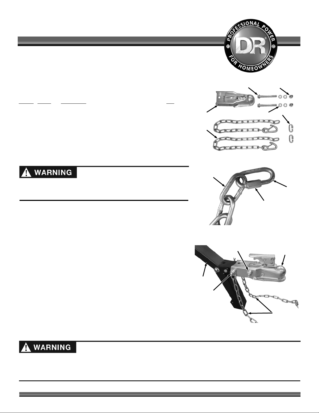
Parts Supplied (Figure 1):
Item #
Part # Description Qty
1 ........... 24648 ....... Receiver, 2", Class II ................................................ 1
2 ........... 33443 ....... Link, Chain, 9/16" ID, 1/4" TH ............................... 2
3 ........... 25312 ....... Safety Chains ........................................................... 2
4 ........... 33349 ....... Bolt, Hex Flange, 1/2-13 x 5", GR8, ZP .................. 2
5 ........... 23499 ....... Washer, Flat, 1/2" ................................................... 4
6 ........... 33335 ....... Nut, Flange, Nylon Lock, 1/2-13, ZP ...................... 2
Compare the contents of the Shipping Box with the “Parts Supplied” list above.
If you have any questions please contact us at www.DRpower.com or call 1-800DR-OWNER (376-9637) for assistance.
Before performing this kit installation, stop the engine, wait five minutes to
allow all parts to cool. Disconnect the spark plug wire, keeping it away from
the spark plug. Disconnect the Battery Terminals (Electric start only).
Installation
1
3
Figure 1
Chain
4
2
Hex
Link
Tools needed:
10mm Wrench
Two 3/4" Wrenches
1. Hook a Link at the end of each Safety Chain and turn the hex portion to
close it onto the Chain (Figure 2). Tighten the Link using a 10mm Wrench.
2. Place the Receiver onto the Tow Bar and align the holes.
3. Slide a Link onto a Bolt followed by a Washer and insert the Bolt through
the rear holes of the Receiver and Tow Bar (Figure 3).
4. Install a Washer first against the Hitch, the Chain Link against the Washer
and then a Flange Nut onto the end of the Bolt. Tighten the Bolt and Nut
using two 3/4" Wrenches.
5. Slide a Washer onto the other Bolt and insert the Bolt through the front
holes of the Receiver and Tow Bar.
6. Install a Washer and Flange Nut onto the end of the Bolt. Tighten the Bolt
and Nut using two 3/4" Wrenches.
Figure 2
Tow Bar
Bolt, Washers
(between
Receiver Hitch
and Links), Chain
Link and Locknut
Figure 3
Bolt, Washers
and Locknut
Receiver
Hitch
Safety
Chain
Attaching to Tow Vehicle
Making sure the Splitter is securely attached to the vehicle is the responsibility of the owner/operator. Failure to securely attach
the Log Splitter can cause loss of control of the vehicle or the Log Splitter being separated from the towing vehicle, resulting in
serious injury or death. If required, use accessory lights and devices when transporting on a road or highway to warn operators of
other vehicles. Check your local government regulations. Safety Chains must always be used when towing.
CONTACT US AT www.DRpower.com 1
Page 2
A
A
Latch
A
ssembly
Figure 4
Tow Hitch
ssembly
Locking Pin
Safety
Chains
Latch
ssembly
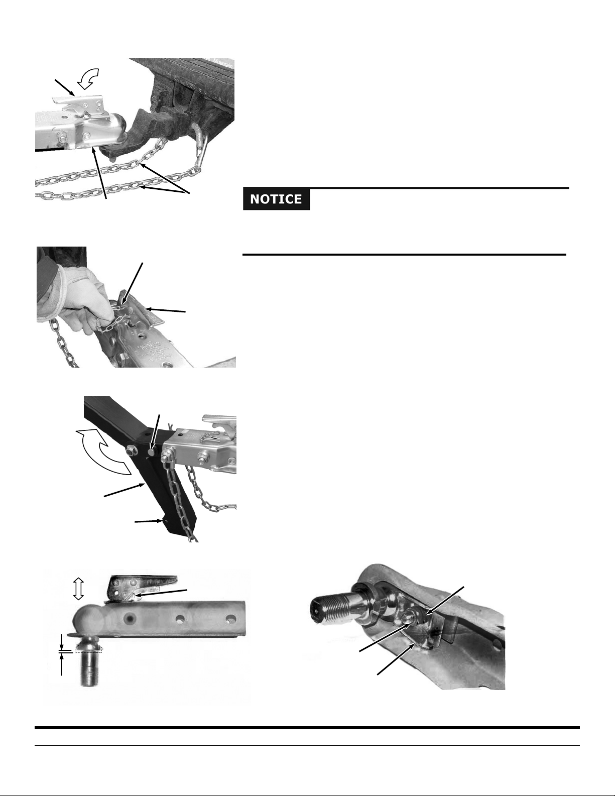
1. Close the Latch Assembly on the Tow Hitch Assembly to lock the Tow Hitch
Assembly onto the Tow Ball (Figure 4). Attach the towing Safety Chains to
the Tow Vehicle ensuring there is enough slack for turning.
2. Make sure the Hitch Coupler is properly and securely attached to the Tow
Ball.
3. Insert the Locking Pin into the hole of the Latch Assembly to lock it in the
closed position (Figure 5).
4. For extra safety and security, you may want to purchase a Lock to install into
the hole of the Latch Assembly.
The folding Support Leg must be rotated up to the transport position when
towing the Log Splitter. Failure to properly secure the Leg up in the transport
position could damage the machine when towing.
5. Pull the Hitch Clip and Clevis Pin from the Support Leg and fold it up to the
transport position. Insert the Clevis Pin through the holes of the Leg and
over the top of the Tow Bar and secure with the Hitch Clip (Figure 6).
Hitch Coupler Adjustment Check
1. Place a 2" Ball in the Socket of the Coupler and close the Latch Assembly
(Figure 7). Verify that the Locking Trigger is properly engaged in its detent.
Figure 5
Support Leg
Figure 6
Pull
Transport
Hole
Hitch Clip
and Clevis Pin
Locking
Trigger
2. Pull on the Ball and/or Coupler, trying to remove the Ball from the Socket. If
the Ball moves more than 1/16" in the Coupler’s Socket, the Clamp requires
adjustment. Follow the proper adjustment procedure in the following steps.
Hitch Coupler Adjustment
1. With the proper size Ball in the Socket of the Hitch Coupler, close the Latch
of the Coupler completely (Figure 8). Verify that the Locking Trigger is
properly engaged in its detent.
2. Tighten the Locknut on the underside of the Coupler until the Spring
between the Nut and the Clamp is fully compressed. Then back off the
Locknut 1/2 turn or just enough that the Latch is able to Clamp and
unclamp from the Ball.
If you have any questions please contact us at www.DRpower.com or call 1-800DR-OWNER (376-9637) for assistance.
Spring
Lock Nut
1/16"
Movement
Figure 7
Figure 8
Ball Clamp
75 MEIGS ROAD, P.O. BOX 25, VERGENNES, VERMONT 05491
©2013 Country Home Products, Inc. All rights reserved 334551
 Loading...