

Page 1
D
R
2
s
RAPIDFIRE™ LOG SPLITTER
Tray Kit# 32130
®
These instructions are for installation of the Tray Kit. Please keep these
instructions with your Splitter Safety and Operating Instructions manual for
future reference.
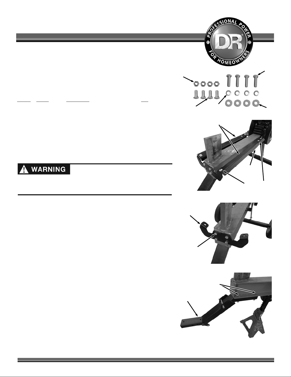
Parts Supplied in Tray Kit (Figure 1):
Item #
Part # Description Qty
1 ............. 313631 ............ Table, Log (not shown) ......................... 1
2 ............. 321041 ............ Bolt, Carriage, 3/8-16 X 1", GR5, ZP ..... 4
3 ............. 333331 ............ Nut, Nylon Lock, Flanged, 3/8-16 ......... 4
4 ............. 150431 ............ Bolt, HHCS, 3/8-16 X 1-1/4", GR5 ........ 4
5 ............. 112411 ............ Washer, Flat, 5/16", USS, ZP ................ 4
6 ............. 180811 ............ Washer, Lock, 3/8" ................................ 4
Compare the contents of the Tray Kit with the “Parts Supplied” list above. If
you have any questions please contact us at www.DRpower.com or call 1-800DR-OWNER (376-9637) for assistance.
Before performing this kit installation, stop the engine, wait five minutes to
allow all parts to cool. Disconnect the spark plug wire, keeping it away from
the spark plug. Disconnect the Battery Terminals (Electric start only).
Tools needed:
Large Jack Stand or equivalent
9/16" Wrench
3
Figure 1
Figure 2
Front Cradle
Bracket
6
Cradles
4
5
Side
Bracket
Carriage Bolts
and Locknuts
Removing the Cradles
1. Support the end of the Beam with a Jack Stand or equivalent to position the
Beam parallel with the ground.
2. Remove the three Carriage Bolts and Locknuts for each Cradle using a
9/16" Wrench and remove the Cradles (Figure 2).
3. Remove the four Bolts and Locknuts the front Cradle Bracket using two
9/16" Wrenches Install to the end of the Beam with (Figure 3).
4. Remove the four Bolts and Lock Washers securing the Tow Bar using two
9/16" Wrenches and remove the Tow Bar (Figure 4).
Bolts and
Locknut
Figure 3
Bolts and
Lock Washers
Tow Bar
Figure 4
CONTACT US AT www.DRpower.com 1
Page 2
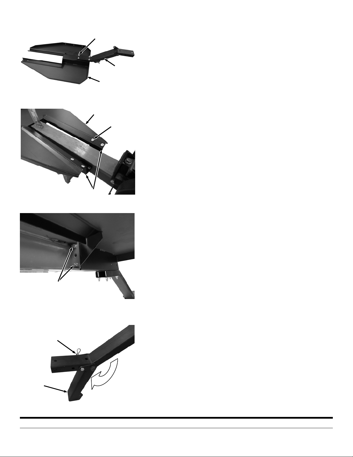
Figure 5
Figure 6
Bolts and Locknuts
Tray
Tray
Side Brackets
Support
Leg
Bolts and
Locknuts
5. Install the Tow Bar to the end Tray with four Bolts and Lock Washers (from
product package) using two 9/16" Wrenches (Figure 5).
6. For easier alignment in the following step, slightly loosen the Side Bracket
Hardware using a 9/16" Wrench (Figure 6).
7. Position the Tray onto the Side Brackets and install the four Carriage Bolts
and Locknuts (from the tray kit) by hand.
8. Install the four Bolts, Lock Washers and Flat Washers (from the tray kit) to
secure the Tray to the end of the Beam using a 9/16" Wrench (Figure 7).
9. Tighten all remaining Tray hardware using a 9/16" Wrench.
10. The Leg may already be in the down position but if it is not then pull the
Hitch Clip and Clevis Pin from the Leg and fold it to the down position.
Align the holes and secure the Leg with the Clevis Pin and Hitch Clip (Figure
8).
11. Remove the Jack Stand and lower the Splitter onto the Support Leg.
If you have any questions please contact us at www.DRpower.com or call 1-800DR-OWNER (376-9637) for assistance.
Beam
Figure 7
Figure 8
Tray
Bolt, Lock Washer
and Flat Washer
Hitch Clip
and Clevis Pin
Support
Leg
75 MEIGS ROAD, P.O. BOX 25, VERGENNES, VERMONT 05491
©2013 Country Home Products, Inc. All rights reserved 334541
 Loading...