

Page 1
de
Gebrauchsanweisung
2
en
Instructions for Use
fr
Notice d’utilisation
es
Instrucciones de uso
it
Istruzioni per l'uso
nl
Gebruiksaanwijzing
da
Brugsanvisning
no
Bruksanvisning
Dräger X-zone 5000
DRAFT 02 - 08/02/10
Page 2

2
For Your Safety . . . . . . . . . . . . . . . . . . . . . . . . . . . . .3
Intended Use . . . . . . . . . . . . . . . . . . . . . . . . . . . . . . .3
Description . . . . . . . . . . . . . . . . . . . . . . . . . . . . . . . .3
What is what . . . . . . . . . . . . . . . . . . . . . . . . . . . . . . .4
Operation . . . . . . . . . . . . . . . . . . . . . . . . . . . . . . . . . .5
Switching on the instrument . . . . . . . . . . . . . . . . . .5
Dräger X-am 5x00 info mode . . . . . . . . . . . . . . . . .6
Switching off the device . . . . . . . . . . . . . . . . . . . .6
Power supply for the Dräger X-am 5x00
with NiMH battery in the Dräger X-zone 5000: . . .6
Perform a function test with gas . . . . . . . . . . . . . .7
Perform a connection test . . . . . . . . . . . . . . . . . . .7
Safety housing . . . . . . . . . . . . . . . . . . . . . . . . . . . .7
Alarm-attenuation ring . . . . . . . . . . . . . . . . . . . . . .7
Establishing a wireless connection . . . . . . . . . . . .8
Connecting devices via a cable connection . . . . .10
Relay output: . . . . . . . . . . . . . . . . . . . . . . . . . . . .11
During operation . . . . . . . . . . . . . . . . . . . . . . . . .12
Alarms (default settings) . . . . . . . . . . . . . . . . . . . .12
Concentration pre-alarm A1 . . . . . . . . . . . . . . . . .13
Concentration main alarm A2 . . . . . . . . . . . . . . .13
Battery pre-alarm . . . . . . . . . . . . . . . . . . . . . . . . .13
Battery main alarm . . . . . . . . . . . . . . . . . . . . . . . .13
Device alarm . . . . . . . . . . . . . . . . . . . . . . . . . . . .13
Operation with pump (optional) . . . . . . . . . . . . . .14
Commissioning and performing the
measurement . . . . . . . . . . . . . . . . . . . . . . . . . . . .14
Observe the following during measuring
mode with pump . . . . . . . . . . . . . . . . . . . . . . . . .15
Device configuration . . . . . . . . . . . . . . . . . . . . . . .15
Faults, Cause, Remedy . . . . . . . . . . . . . . . . . . . . .16
Fault messages . . . . . . . . . . . . . . . . . . . . . . . . . 18
Maintenance . . . . . . . . . . . . . . . . . . . . . . . . . . . . . .19
Maintenance intervals . . . . . . . . . . . . . . . . . . . . .19
Replacing the batteries . . . . . . . . . . . . . . . . . . . .19
Charging the batteries . . . . . . . . . . . . . . . . . . . . .20
Care . . . . . . . . . . . . . . . . . . . . . . . . . . . . . . . . . . . . .20
Disposing of the device . . . . . . . . . . . . . . . . . . . . .20
Technical Data . . . . . . . . . . . . . . . . . . . . . . . . . . . .21
Key allocation of Dräger X-zone 5000 . . . . . . . . . .22
Status LED Overview . . . . . . . . . . . . . . . . . . . . . . .22
Overview of LED Ring and Horn Signals . . . . . . .24
Order List . . . . . . . . . . . . . . . . . . . . . . . . . . . . . . . . .25
Contents
DRAFT 02 - 08/02/10
Page 3
3
For Your Safety
Strictly follow the Instructions for Use
Any use of the device requires full understanding and
strict observation of these Instructions for Use. The
device is only to be used for the purposes specified
here.
Maintenance
The device must be inspected and serviced regularly by
trained service personnel. Repair of the device may only
be carried out by trained service personnel.
We recommend that a service contract be obtain ed with
Dräger and that all repairs also be carried out by Dräger.
Only genuine Dräger parts should be used for
maintenance.
Strictly follow the instructions in the chapter
"Maintenance intervals" on Page 18.
Accessories
Do not use accessory part s other than those specified in
the order list Page 24.
Safe coupling with electrical device s
Electrical connections to devices which are not listed in
these Instructions for Use should only be made
following consultation with the respective manufacturers
or an expert.
Use in areas subject to explosion hazards
Devices or components for use in explosion-hazard
areas which have been tested and approved according
to national, European or international Explosion
Protection Regulations may only be used under the
conditions specified in the approval and with
consideration of the relevant legal regulations.
The equipment or components may not be modified in
any manner. The use o f faulty or incomple te parts is
forbidden. The appropriate regulations must be
observed at all times when carrying out repairs on
these devices or components.
Safety symbols used in these Instructions for Use
These Instructions for Use contain a number of
warnings for risks and hazards which might occur when
using the instrument. These warnings contain signal
words which will alert you to the degree of hazard you
may encounter . These signal words and correspo nding
hazards are as follows:
Intended Use
The Dräger X-zone 5000 is an explosion-proof, portable
alarm amplifier for the quasi-stationary monitoring of
hazard areas. The Dräger X-zone 5000 can be used in
combination with the Dräger X-am 5000/5600 gas
detection instruments. Several Dräger X-zone 5000
devices can operate in a self-crosslinking network.
Description
The Dräger X-zone 5000 alarm amplifier is intended for
use under industrial conditions within a specified
temperature range for an uninterrupted o perating period
of up to 5 days.
Via a wireless connection and/or communication ca ble,
several Dräger X-zone 5000 devices can be grouped to
form an alarm chain. In the event of an alarm, all
connected Dräger X-zone 5000 devices will issue the
alarm.
The alarm is generated using the gas detection
instrument
Dräger X-am 5x00. The Dräger X-am 5x00 is connected
via an infrared interface
to the Dräger X-zone 5000. In addition to alarm
generation, the Dräger X-am 5x00 is used as the user
interface for the Dräger X-zone 5000. When the Dräger
X-am 5x00 generates a gas alarm, this is transmitted to
the Dräger X-zone 5000 and amplified acousticall y and
optically.
DANGER
Indicates an immediate hazardous situatio n whic h, if
not avoided, could result in death or serious injury.
WARNING
Indicates a potential hazardous situation which, if no t
avoided, could result in death or serious injury.
CAUTION
Indicates a potential hazardous situation w hic h, if not
avoided, could result in injury or damage to property.
It may also be used to alert against unsafe practices.
NOTICE
Additional information on how to use the device.
NOTICE
The Dräger X-zone 5000 is intended for detection in
ambient air. Any increased exposure to certain
hydrocarbons can result in restrictions in the detection
quality of the electrochemical sensors.
DRAFT 02 - 08/02/10
Page 4
4
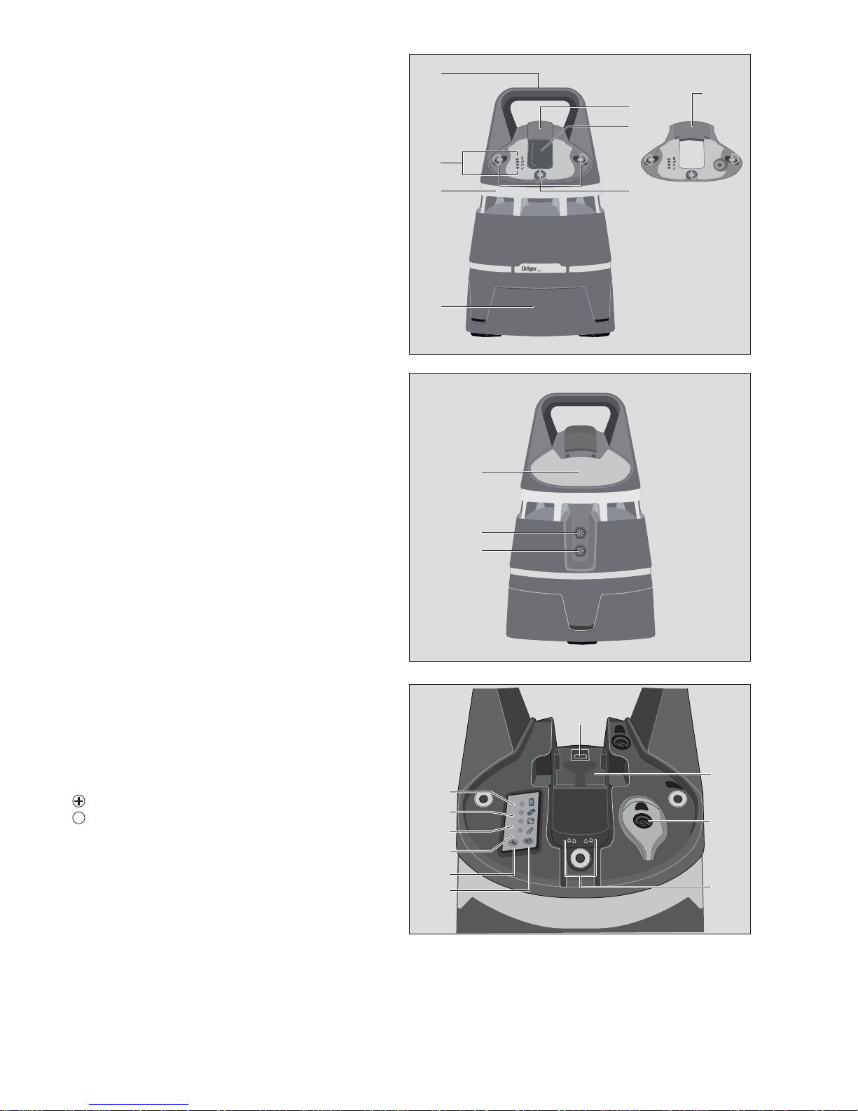
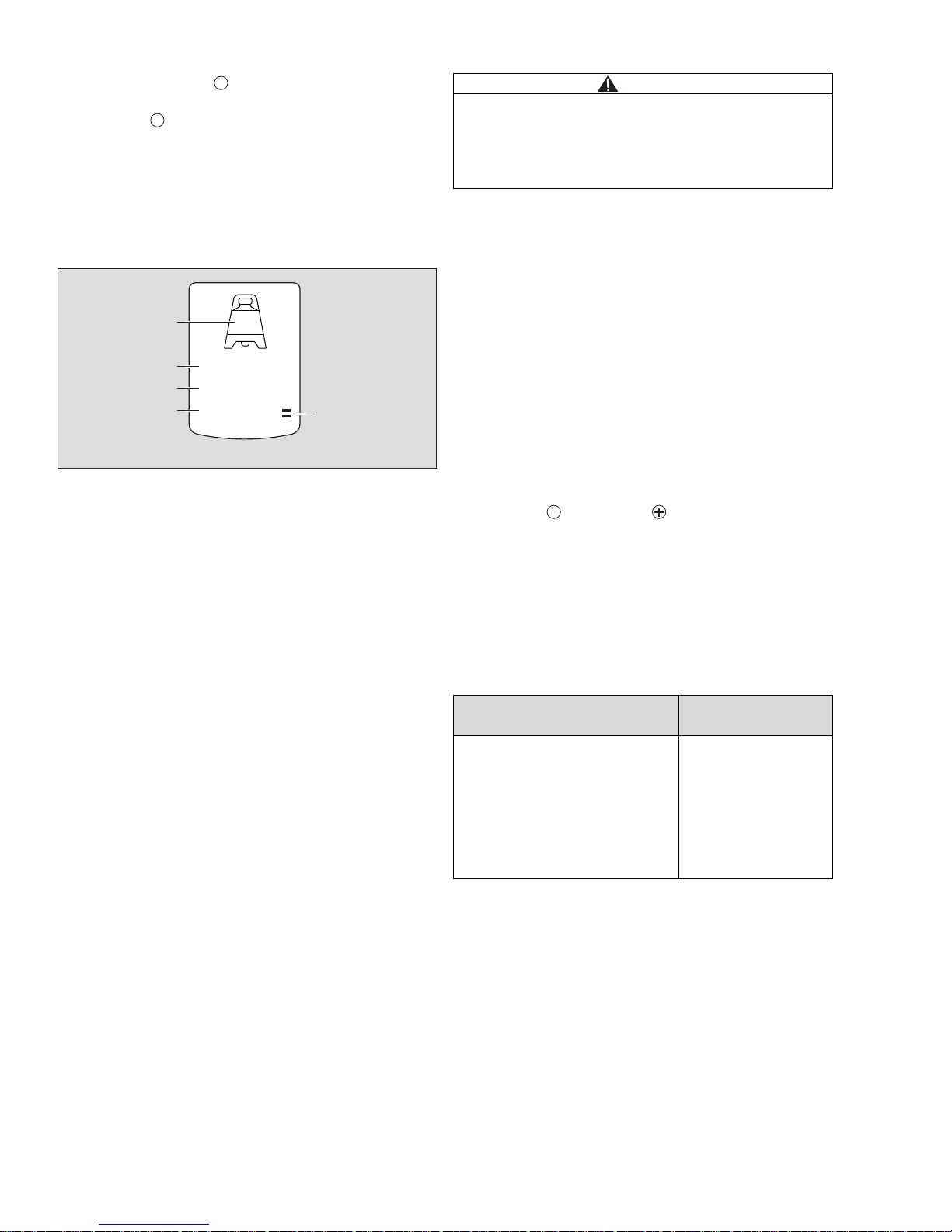
What is what
Front
1 Carrying handle
2 LED indicators
3 LED alarm ring
4 Inductive charging station
5 Lock
6 Device receptacle
7 Dräger X-am 5x00 holder diffusion mode
8 Dräger X-am 5x00 holder pump mode (optional)
Rear side
9 Quick-reference guide
10 Switch relay conn ec tio n / RS48 5 co nn ec tio n
11 Charging port connection / RS485 connection
Display
12 IR interface
13 Battery LED
14 Data transmission LED
15 Pump LED
16 Grouping LED
17 /wireless network key
18 key
19 Power contacts for Dräger X-am 5x00
20 Pump inlet (optional)
21 Pump outlet (optional)
OK
1
2
3
4
5
6
7
x-zone 5000
8
00233112.eps
10
11
9
00333112.eps
12
17
13
14
15
16
19
20
18
21
DRAFT 02 - 08/02/10
Page 5
5
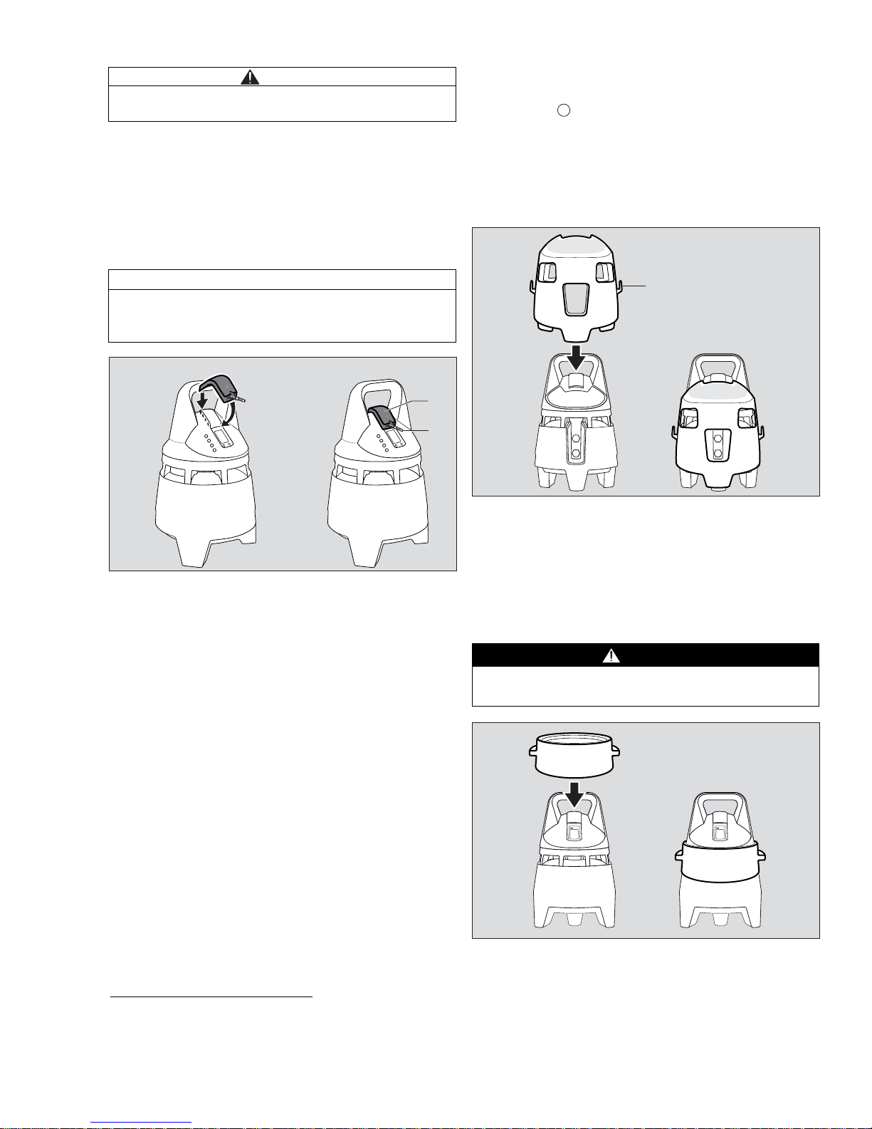
Operation
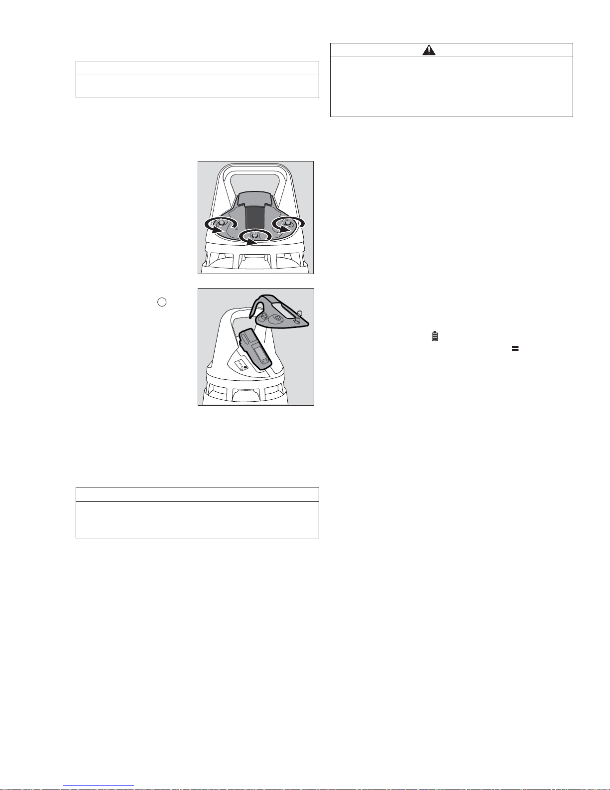
Switching on the instrument
STANDBY mode
z Place the Dräger X-am 5x00 into the device
receptacle.
z Place the holder onto the housing.
z Fasten the lock at the holder.
ON mode
z Switch on the Dräger X-am 5x00 in accordance with
the instructions for use.
– The visual and the audible alarm will be activated for
a short time.
– The Dräger X-am 5x00 switches to the X-zone mode
(refer to “X-zone mode:” on page 5).
– The visual and acoustic life signal (green LED ring
and single tone) is issued depending on the
configuration (1 - 60 seconds; default setting:
2 seconds).
– The Dräger X-zone 5000 is in the ON mode and
ready for operation.
– In ON mode, the alarm signals of the Dräger X-am
5x00 are evaluated, processed, and, if applicable,
transmitted to other Dräger X-zone 5000 devices.
X-zone mode:
– The battery symbol on the Dräger X-am 5x00 is
replaced by the X-zone mode symbol
on the
Dräger
X-zone 5000.
– The Dräger X-am 5x00 is supplied via the Dräger
X-zone 5000 battery.
– If the activated Dräger X-am 5x00 is removed from
the Dräger X-zone 5000, the device will exit X-zone
mode again after max. 10 seconds.
NOTICE
Only Dräger X-am 5x00 devices of software version
3.5 and later are compatible with Dräger X-zon e 5000.
z Release the lock on
the holder.
z Remove the holder.
z Hold down the key
on the
Dräger X-zone 5000
for approx. 3 seconds.
– The battery LED will be
lit in green, red/green
or red (refer to “Status
LED Overview” on
page 21) depending on
the battery capacity.
– The Dräger X-
zone 5000 is in the
STANDBY mode.
NOTICE
The Dräger X-am 5x00 must be equipped with a NiMH
battery.
The clip on the Dräger X-am 5x00 must be connected.
00433112.eps
OK
CAUTION
When switching on the Dräger
X-zone 5000, Dräger recommends wearing hearing
protection or using the alarm-attenuation ring (order
no. 83 20 1 10) as the acoustic alarm is activate d for a
brief period.
DRAFT 02 - 08/02/10
Page 6
6
Dräger X-am 5x00 info mode
z Press and hold the key of the Dräger X-am 5x00
for approx. 3 seconds in detection mode.
– Press the key successively for the next display.
The peak values and the exposition values TW A and
STEV as well as additional X-zone information will
be displayed.
If there are warnings or faults, the corresponding
notes or error codes (e. g. X01) are displayed (refer
to “Fault messages” on page 17).
Info window for Dräger X-am 5x00:
1 Station number in grouping mode:
The station number is not currently supported by the
Dräger X-zone 5000.
2 Wireless status: ON/OFF:
Displays whether the wireless function of the Dräger
X-zone 5000 is switched on or off.
The wireless function can be switched on and off
using the Dräger CC-Vision PC software (refer to
“Device configuration” on page 14).
3 Network number:
If independent radio networks are required, dif ferent
network numbers must be assigned (refer to
“Establishing a wireless connection” on page 8).
The network number can be set using the Dräger
CC-Vision PC software (refer to “Device
configuration” on page 14).
4 Grouping ID:
The grouping ID is not currently supported by the
Dräger X-zone 5000.
5 X-zone mode symbol
Displays whether or not there is a connection
between the Dräger X-zone 5000 and the Dräger Xam 5x00.
– If no key is pressed for 10 seconds, the Dräger X-am
5x00 returns automatically to detection mode.
Switching off the device
STANDBY mode
z Switch off the Dräger X-am 5x00 in the Dräger X-
zone 5000 in accordance with the instructions for
use.
– The visual and the audible alarm will be activated for
a short time before the Dräger X-zone 5000 switches
off.
– The Dräger X-zone 5000 switches to the ST ANDBY
mode.
OFF mode
z Release the lock at the holder.
z Remove the holder.
z If necessary , remove the Dräger X-am 5x00 from the
device receptacle.
z Press the key and the key on the Dräger X-
zone 5000 and hold down for approx. 3 seconds.
– The battery LED goes off.
– The Dräger X-zone 5000 is switched off
(OFF mode).
Power supply for the Dräger X-am 5x00
with NiMH battery in the Dräger X-zone
5000:
OK
OK
RF:
NET:
P\N:
ON
--
005
FFFF
1
2
3
4
5
CAUTION
When switching off the Dräger
X-zone 5000, Dräger recommends wearing hearing
protection or using the alarm-attenuation ring (order
no. 83 20 110) as the acoustic alarm is activated for a
brief period.
Device mode
Power supply for the
Dräger X-am 5x00
Dräger X-zone 5000: ON mode
Dräger X-am 5x00: Switched on
Dräger X-am 5x00 is
permanently supplied with
power.
Dräger X-zone 5000: STANDBY mode
Dräger X-am 5x00: Switched off
Dräger X-am 5x00 is
supplied with power via
trickle charging.
Dräger X-zone 5000: OFF mode
Dräger X-am 5x00: Switched off
Dräger X-am 5x00 is not
supplied with power.
OK
DRAFT 02 - 08/02/10
Page 7
7
Perform a function test with gas
The function test can be carried out in two ways.
Function test for the Dräger X-am 5x00:
z Perform a function test in accordance with the
instructions for use for the gas detection instrument
before using with the Dräger X-zone 5000.
Function test on the Dräger X-am 5x00 in
combination with the Dräger X-zone 5000:
z Switching on Dräger X-zone 5000 (refer to
“Switching on the instrument” on page 5).
z Place adapter (1) (order no. 83 20 108) on the holder
(diffusion).
z Connect the test gas cylinder to the adapter (2).
z Open the test gas cylinder valve to let test gas flow
over the sensors.
z Wait until the instrument displays the test gas
concentration with sufficient tolerance:
Ex: ±20 %
1)
O2: ±0.8 Vol.-%
1)
TOX: ±20 %1).
– Depending on the test gas concentration, alarm A1
or A2 is issued when the alarm thresholds are
exceeded.
z Close the test gas cylinder valve and remove the
adapter from the holder.
If the displays are outside of the above-mentioned
ranges: Have the Dräger X-am 5x00 calibrated by
service personnel.
Perform a connection test
The connection test can be used to check the correct
connection to all Dräger X-zone 5000 devices.
z Press the key on of the the Dräger X-am 5x00
devices being used three times in succession.
A signal via a horn and LED ring is issued three times
on every device connected wirelessly or via a cable.
Safety housing
In exceptionally rough environments, and in ver y strong
sunlight and high temperatures (> +40 °C), the use of
the safety housing (order no. 83 21 519) is
recommended.
1 Hose/cable holder
Alarm-attenuation ring
When switching on and off and during the function test
of the Dräger X-zone 5000, Dräger recommends
wearing hearing protection or using the alarmattenuation ring (order no. 83 20 110) as the acoustic
alarm is sounded for a short time.
CAUTION
A function test must be carried out on every device
before use.
NOTICE
The function test can only be carried out with the
Dräger X-am 5x00 holder diffusion mode (ord er no.
83 20 636).
1) Upon application of the Dräger mixed gas (order no. 68 11130)
the displays should be within this range. Different concentrations
can be set using the Dräger CC-Vision PC software provided.
02733112.eps
1
2
WARNING
The alarm-attenuation ring must not be used in
explosion-hazard areas!
OK
1
03033112.eps
DRAFT 02 - 08/02/10
Page 8
8
Establishing a wireless connection
Up to 25 devices can be connected on a wireless
network via a wireless connection.
The typical radio range is up to 100 m in industrial
surroundings (environmental factors may affect the
range).
The devices can be operated in a chain, star or ring
topology. It is possible to establish an open radio
network or independent radio networks. All devices
within radio range are automatically connected.
Open wireless network (standard configuration):
With an open wireless network, any number of Dräg er
X-zone 5000 devices (up to 25) can be added to or
removed from a wireless network number.
Independent radio networks:
If independent radio networks are required, different
network numbers need to be assigned for the relevant
radio networks (refer to “Device configuration” on
page 14).
Example:
Two independent radio networks each with three Dräger Xzone 5000 devices should be created. To do this, the
Dräger CC-Vision PC software should be used to set
NET:001 with three Dräger X-zone 5000 devices and
NET:002 for three further Dräger X-zone 5000 devices.
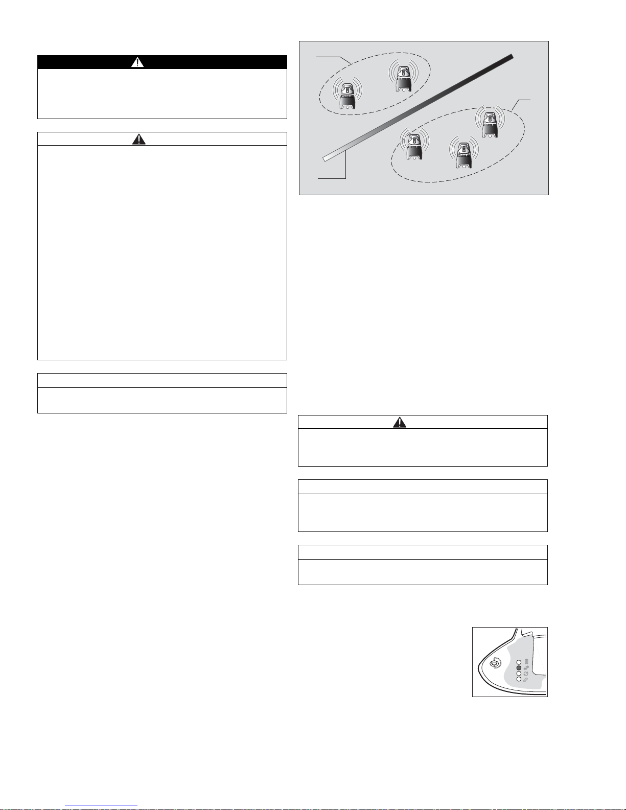
Sub-networks:
1 Sub-network 1
2 Sub-network 2
3 e. g. steel wall, wall, HGV, etc.
Sub-networks are created via an unintentional division
of the open network into two or more radio networks.
This can occur if the user is running two activated
Dräger X-zone 5000 (with the same network number).
This means that the devices have permanently
interconnected wireless connection (data transmission
LED is lit in green). This means that the user can no
longer tell whether or not the wireless connection is
already set up with the devices already installed. To
avoid sub-networks, the Dräger X-zone 5000 devices
should always be set up and switched on in succession.
Positioning the device:
z Switch on the first Dräger X-zone 5000 (refer to
“Switching on the instrument” on page 5) and
position at the relevant location.
WARNING
A maximum of 25 Dräger X-zone 5000 devices may be
connected on a wireless network as otherwise it is not
possible to ensure a reliable connection and alarm
forwarding.
CAUTION
FCC and IC:
This device complies with Part 15 of the FCC Rules.
Operation is subject to the following two conditions:
– this device may not cause harmful interference,
and
– this device must accept any interference received,
including interference that may cause undesired
operation.
Modifications not expressl y ap pr ov ed by this company
could void the user's authority to operate the
equipment. The internal / external antennas used for
this mobile transmitter must provide a separation
distance of at least 20 cm from all persons and must not
be co-located or operating in conjun ction with any other
antenna or transmitter. This device and its antenna
must not be co-located or operating in conjunction with
any other antenna or transmitter.
NOTICE
If the devices are in ON mode, they automatically
establish the wireless connection.
CAUTION
Before positioning the devices, a function test (refer to
“Perform a function test with gas” on page 7) must be
conducted on every device.
NOTICE
The gas supply must be connected at an angle of 360°.
If required, use base (order no. 83 20 645) to raise the
detection position by approx. 30 cm.
NOTICE
When positioning the devices, ensure that subnetworks are avoided.
z Switch on the second Dräger X-
zone 5000 and position at a
distance so that the data
transmission LED is lit in green.
– The wireless connection is
established and the data
transmission LED indicates the
connection to at least one device
within radio range.
03533112.eps
1
3
2
DRAFT 02 - 08/02/10
Page 9

9
z Position other Dräger X-zone 5000 devices using the
same process.
Examples of use:
Setting A:
Monitoring industrial tanks
(Wireless alarm chain)
Setting B:
Area monitoring with pump
Setting C:
Radio monitoring of pipelines
(Wireless alarm chain)
WARNING
If the data transmission LED is lit in red, the distance
from the next device must be reduced.
NOTICE
Dräger recommends performing a function test (re fer to
“Perform a connection test” on page 7) after positioning
all the devices.
01833112.eps
A
01933112.eps
B
C
DRAFT 02 - 08/02/10
Page 10

10
Connecting devices via a cable connection
If radio connections are not allowed or blocked, the
devices can be connected via communication cable.
The maximum cable length between two devices is
25 m.
z Switching on Dräger X-zone 5000 (refer to
“Switching on the instrument” on page 5).
z
Plug the communication cable into the charging port/
RS485 connection (1) on the rear side of the device.
z Connect the end of the communication cable to the
switch relay/RS485 connection (2) of the second
device.
z If required, connect further devices via
communication cable as described above.
Pin configuration XEXT1 / XEXT2 on the device:
XEXT2 (male)
RS485
1 PLUS
2 MINUS
3 GND
Relay output
4 Normally Closed (NC)
5 Normally Open (NO)
6 Closed Only (CO)
7 GND
XEXT1 (female)
RS485
1 PLUS
2 MINUS
3 GND
Charger
4 Additional voltage (U-I
n
)
5 GND2
CAUTION
Before positioning the devices, a function test (refer to
“Perform a function test with gas” on page 7) must be
conducted on every device.
NOTICE
Due to widely differing customer-specific r equirements,
Dräger does not provide any communication cables. All
relevant cable parameters are described in this
chapter.
NOTICE
Combined wireless and cable operation is possible.
– The data transmission LEDs of the
coupled devices light green.
WARNING
If the data transmission LED is lit in red, check the
cable connection.
NOTICE
Dräger recommends performing a function test (refer to
“Perform a connection test” on pag e 7) after positioning
all the devices.
01233112.eps
2
1
01333112.eps
02133112.eps
176
25
34
671
52
43
XEXT2
XEXT1
DRAFT 02 - 08/02/10
Page 11

11
RS485 connection:
1 Plug (male):
Housing: Souriau UTS6JC147P (male)
Contacts: Souriau RM20M12K (male)
2 Plug (female):
Housing: Souriau UTS6JC147S (female)
Contacts: Souriau RC20M12K (female)
3 Cable type: Belden 3107A, 2 x 2 AWG 22
Cable length: max. 25 m between 2 devices
Relay output:
The relay output is intended for connection to an
isolation amplifier with intrinsically safe output.
1 Plug (female):
Housing: Souriau UTS6JC147S (female)
Contacts: Souriau RC20M12K (female)
2 Configure the pin assignment separately dep ending
on the application
3 Cable type: Belden 3107A, 2 x 2 AWG 22
Cable length: max. 25 m between 2 devices
CAUTION
Ensure that the cable strands are not crossed !
02333112.eps
XEXT1
XEXT2
1
2
3
1
2
3
1
2
3
1
2
3
1
2
3
1
2
3
03133112.eps
2
max. 25 m
1
3
WARNING
It is essential that the parameters of the relay outputs
are observed to prevent the circuit from jeopardising
the intrinsic safety of the device.
Only intrinsically safe circuits are permitted for
connection.
NOTICE
The person responsible for the use of the Dräger Xzone 5000 must prepare a system document to verify
the intrinsic safety level.
5
6
4
NO
CO
NC
XEXT2
1
2
3
6
5
4
1
max. 25 m
2
3
DRAFT 02 - 08/02/10
Page 12

12
Connection of the relay output
During operation
During operation the values for each gas detected are
displayed on the inserted Dräger X-am 5x00.
The visual and acoustic life signal (LED ring green and
single tone) is issued depending on the configuration
(1 - 60 seconds; default setting every 2 seconds). The
life signal can be configured using the Dräger CC-Vision
PC software (refer to “Device configuration” on
page 14).
In the event of an alarm, the visual and the audible
alarm will be activated (refer to “Alarms (default
settings)” on page 11).
The Dräger X-zone 500 will amplify the visual and
audible alarm and will permanently transmit the alarm
information, via a wireless connection or via cable, to
further Dräger X-zone 5000 devices.
Alarms (default settings)
The Dräger X-zone 5000 is equipped with two different
alarm generators:
– Visual signal: LED ring (360°);
Colours red, green; pulsing.
– Acoustic signal: Intense horn (108 dB (A) in 1 m
distance/120 dB (A) in 30 cm distance).
Triggering device:
As soon as a device detects an increased gas
concentration, this device will become the triggering
device.
The triggering device forwards the alarms to all
connected devices wirelessly and/or via communication
cable.
Receiving device:
All devices that receive an alarm from the triggering
device become receiving devices. The receiving
devices generate a seconary alarm. If the receiving
device does not receive any information from the
triggering device, the secondary alarm on the rece iving
devices is cancelled after 10 seconds.
Maximum voltage (U
i
): 20 V
Maximum continuous current
(I
i
):
0.15 A
Maximum switching capacity
(P
i
):
3W
For ohmic loads only:
Reactances: C
i
≤ 100 pF Li ≤ 10 µH
NOTICE
The displays on the Dräger X-am 5x00 are described in
the instructions for use for the gas detection in strument
being used.
NOTICE
The alarm settings (e. g. self-latching/
acknowledgeable) can be configured using the Dr äger
CC-Vision PC software. The configuration of the
Dräger X-am 5x00 is critical for the correct response of
the Dräger
X-zone 5000.
NOTICE
The alarm-triggering device and the receiving d evices
give a different visual alarm.
DRAFT 02 - 08/02/10
Page 13

13
Concentration pre-alarm A1
The alarm is indicated by an
intermittent alarm message:
Display » A1 « and measured value alternating: not for
O2!
– The pre-alarm A1 is not self-latching and stop s when
the concentration has dropped below alarm
threshold A1.
The triggering device at A1:
– A single tone sounds and the LED ring flashes red
(main alarm).
The receiving device at A1:
– A single tone sounds and the LED ring flashes red/
green (seconary alarm).
Acknowledging the pre-alarm:
z Press key on the Dräger X-am 5x00 of the
triggering
Dräger X-zone 5000.
– Only the audible alarm will be switched off.
Concentration main alarm A2
The alarm is indicated by an
intermittent alarm message:
The triggering device at A2:
– A double tone sounds and the LED ring flashes red
twice (main alarm).
A receiving device at A2:
– A double tone sounds and the LED ring flashes red/
green twice (seconary alarm).
Only after the concentration has dropped below the
alarm threshold A2:
z Press key on the Dräger X-am 5x00 of the
triggering
Dräger X-zone 5000.
– The alarm messages will be switched off.
Battery pre-alarm
The alarm is indicated by an
intermittent alarm message:
Acknowledging the pre-alarm:
– The Battery LED flashes red.
z Press key on the Dräger X-am 5x00 of the
Dräger X-zone 5000, only the acoustic alarm is
switched off.
– After the first battery pre-alarm the battery will last for
another approx. 15 minutes.
Battery main alarm
The alarm is indicated by an
intermittent alarm message:
The battery main alarm cannot be acknowledged
acoustically:
– The Battery LED flashes red.
– The device automatically switches off after
10 seconds.
The visual and the audible alarm will be activated for a
short time before the device switches off.
Device alarm
The alarm is indicated by an
intermittent alarm message:
– The device or one or more sensor channels are not
ready for operation.
– Remedies, refer to “Faults, Cause, Remedy” on
page 15
z If necessary , commission the Dräger Safety Service
Centre to eliminate the error.
Acknowledge the device alarm
z Press the key on the Dräger X-am 5x00 or on the
Dräger
X-zone 5000.
DANGER
Danger to life! Leave the area immediately.
A main alarm is self-latching and cannot be
acknowledged (see Dräger X-am 5x00 Instructions for
Use).
For O
2
: A1 = lack of oxygen
A2 = excess oxygen
WARNING
Before the area may be entered again, a clearance
measurement must be performed!
OK
OK
NOTICE
Indicates a malfunction of the Dräger X-zone 5000 or
the Dräger X-am 5x00.
OK
OK
DRAFT 02 - 08/02/10
Page 14

14
Operation with pump (optional)
The Dräger X-zone 5000 is equipped with a pump as an
option (refer to “Order List” on page 24.)
Commissioning and performing the
measurement
z Release the lock on the holder.
z Remove the holder.
z Press the key of the Dräger X-zone 5000 and
hold it for approx. 3 seconds.
– The Dräger X-zone 5000 is in STANDBY mode.
z Place the Dräger X-am 5x00 into the device
receptacle.
z Place the holder (pump) onto the housing.
z Fasten the lock at the holder (pump).
z Switch on the Dräger X-am 5x00 in accordance with
the instructions for use.
– If the device is in the ON mode, the pump will be
automatically switched on via a switching contact on
the holder (pump).
– Pump LED flashes red/green.
z A pump test will then need to be performed. The
pump test will start automatically.
Pump test
If the test was successful:
If the test was not successful:
Ending operation
z Switch off the Dräger X-am 5x00 in accorda nce with
the instructions for use.
– The visual and the audible alarm will be activated for
a short time before the device switches off.
– The Dräger X-zone 5000 switches to STANDBY
mode.
z Unscrew the sampling hose or the Dräger probe
from the filter.
z Remove the holder (pump) by releasing the lock.
– The pump switches off.
z Place the holder onto the housing.
z Fasten the lock at the holder.
CAUTION
Pump operation only with filter (order no. 83 19 359)!
Otherwise there is a risk of damage to the pump.
If no filter is used during pump operation, the war ranty
on the pump becomes invalid.
z Connect the sampling
hose with the water
trap for the hose set
(order no. 68 05 473)
and screw the
connecting bush onto
the filter in a clockwise
direction.
NOTICE
The pump test must be performed within 60 seconds
otherwise a device alarm is issued.
OK
NOTICE
Pump test is performed in the same way as for the
Dräger pump
X-am 1/2/5000.
During the pump test, in the default
setting the acoustic alarm is automaticallyreduced to
80 dB (A).
– The pump LED flashes red/green,
accompanied by a signal tone.
z Seal or kink the intake flange or
sampling hose for approx.
2 seconds.
– The pump LED lights red.
– Unblock the intake flange/
sampling hose.
– The pump LED lights green,
accompanied by an acoustic
acknowledgment signal.
– The pump LED lights red,
accompanied by a continuous
tone.
– The pump switches off
automatically.
DRAFT 02 - 08/02/10
Page 15

15
Observe the following during measuring
mode with pump
z Wait for the flushing time to elapse:
Before every measurement, flush the Dräger
sampling hose or the Dräger probes with the air
sample to be measured.
– A flushing phase is necessary to eliminate or
minimise all effects associated with the use of a
sampling hose or a probe, e. g. abso rp tio n in the
hose, dead volume.
– The duration of the flushing phase depends on
factors such as type and concentration of the gas or
vapour to be measured, material, length, diameter,
and age of the sampling hose or probe. Generally,
when using a sampling hose (new, dry, clean), a
typical flushing time of approx. 10 seconds is
required for each metre. This flushing time applies in
addition to the sensor response time (see the
Instructions for Use for the gas detection instrument
used).
Example:
– In the case of a 10 m sampling hose, the flushing
time is approx. 100 seconds and the sensor
response time is in addition approx. 60 seconds.
Therefore, the total time before reading the gas
detection instrument is approx. 90 seconds.
– The flow-rate alarm is delayed by 10 to 30 seconds
depending on the length of the hose.
Replacing the filter
z Unscrew the connecting bush from the filter.
z Unfasten the lock at the holder (pump).
z Remove the holder (pump).
z Place the holder (pump) onto the housing.
z Fasten the lock at the holder (pump).
z Screw the connecting bush onto the new filter.
Device configuration
To individually configure a standard-configuration
device, connect the device to a PC.
Communication is carried out via the USB DIRA dongle
(order no. 83 17 409).
The Dräger CC-Vision PC software is used to perform
the configuration.
The following settings can be configured, among oth ers:
– Horn volume
– Wireless function
– Alarm frequencies
– Alarm pattern
– Alarm forwarding
– Life signal (light pattern, horn volume)
– Bump test volume
(Default setting: 80 dB (A))
– Actions of the switch relay
z Unscrew the filter anti-
clockwise.
z Screw a new filter
(order no. 83 19 359)
onto the device in a
clockwise direction.
NOTICE
Observe the documentation and online help of Dräger
CC Vision PC software.
NOTICE
A Dräger CC Vision version, which can be used for
Dräger X-zone 5000 PC software, is supplied with the
device on CD-ROM.
IR
DRAFT 02 - 08/02/10
Page 16

16
Faults, Cause, Remedy
Fault Cause Remedy
Dräger X-zone 5000 cannot
be loaded.
Charging unit plug is not in correct
contact with the Dräger X-zone
5000.
Ensure that the charging unit plug is
correctly plugged in.
Check the battery LED.
Battery service life is low. Battery is not fully charged. Load battery for at least 12 h.
Battery not regularly charged. Charge battery regularly even when
switched off, at least every
2months.
Outdoor temperature is too low. Warm up Dräger X-zone 5000.
Outdoor temperature is very high. Use safety housing where
appropriate.
Battery is faulty. Have the battery checked by the
Dräger service department.
Inductive charging is not functioning
correctly as the distance between
the Dräger X-zone 5000 and the
charging station is too great.
Check the distance, remove any dirt
if necessary.
No wireless connection between the
Dräger X-zone 5000 devices.
Wireless function is not activated. Activate the wireless function using
the Dräger CC-Vision PC software
(refer to “Device configuration” on
page 14).
Dräger X-zone 5000 devices are
very far apart.
Position the Dräger X-zone 5000
devices more closely together.
Position additional devices in the
chain.
Place Dräger X-zone 5000 at a
higher position, use base (order no.
83 20 645) where appropriate.
The wireless connection is made
more difficult by an industrial
environment: e. g. steel walls.
Position the Dräger X-zone 5000
devices more closely together.
Position additional devices in the
chain.
Connect the Dräger X-zone 5000
with a communication cable (refer to
“Connecting devices via a cable
connection” on page 9).
Dräger X-zone 5000 are covered by
conductive materials (e. g. metal
grids).
Ensure there are no obstructions.
Network number of the Dräger
X-zone 5000 is different.
Use Dräger X-zone 5000 devices
with the same network numbers.
The network number can be
configured using the Dräger CC-
Vision PC software (refer to “Device
configuration” on page 14).
Wireless frequency of the Dräger
X-zone 5000 devices is different.
Use Dräger X-zone 5000 devices
with the same radio frequency.
Cable connection is not functioning. Cable plug is not correctly plugged
in, cable assignment is incorrect or
cable is broken.
Check cable connection and
assignment. Ensure that the cable
plug is correctly plugged in.
Alarm contact is not switching. Cable plug is not correctly plugged
in, cable assignment is incorrect or
cable is broken.
Check cable connection and
assignment. Ensure that the cable
plug is correctly plugged in.
Pump operation is not functioning. Incorrect holder (diffusion) in
position.
Position the holder (pump).
DRAFT 02 - 08/02/10
Page 17

17
Pump fault during operation. Condensate formation with cold and
damp intake air.
Use hose set with water trap (order
no. 83 21 527).
Pump outside the specified range. Have the pump checked by the
Dräger service department.
Function test has failed. Incorrect holder (pump) in position. Use holder (diffusion).
Adapter is incorrectly positioned on
the holder (diffusion).
Position adapter correctly on the
holder (diffusion) (refer to “Perform
a function test with gas” on page 7).
Flow test has failed. Flow test has not been performed. Perform flow test, repeat if
necessary.
Holder (pump) is not correctly
positioned.
Re-position holder (pump) and
check that it is correctly fitted.
Horn is too quiet. Volume is set too low. Set the volume using the Dräger
CC-Vision PC software (refer to
“Device configuration” on page 1 4).
Optical alarm signals not visible or
poorly visible.
Configuration or pattern incorrectly
set.
Configure the alarm signals using
the Dräger CC-Vision PC software
(refer to “Device configuration” on
page 14).
Life signal is not functioning. Configuration is set incorrectly. Configure the life signal using the
Dräger CC-Vision PC software
(refer to “Device configuration” on
page 14).
Gas detection instrument not
detected.
IR interface dirty. Clean IR interface.
Incompatible gas detection
instrument.
Use Dräger X-am 5x00.
Incorrect software version in the gas
detection instrument.
Have a software update performed
by the Dräger service department.
IR interface faulty, clip on gas
detection instrument not correctly
positioned.
Close clip on Dräger X-am 5x00.
Holder is not correctly positioned. Re-position ho lde r an d chec k that it
is correctly fitted.
Dräger X-am 5x00 switches off
quickly; no power supply.
Power contacts dirty or damp. Clean power contacts.
Device defect displayed. Dräger X-am 5x00 moved away
from Dräger X-zone 5000 during
operation.
Acknowledge alarm on Dräger X-
zone 5000, switch off Dräger X-zone
5000.
Fault Cause Remedy
DRAFT 02 - 08/02/10
Page 18

18
Fault messages
Special symbol » « and
displayed numerical
code:
Cause Remedy
01 Dräger X-am 5x00 with alkali supply unit. Insert Dräger X-am 5x00 with battery
power pack.
02 Communication interrupted with
Dräger X-zone 5000.
Check IR interface on Dräger X-zone
5000 and on Dräger X-am 5x00.
03 Communication error with battery
controller
Dräger X-zone 5000.
Contact Dräger service department.
04 Main battery alarm Dräger X-am 5x00. Check charging contacts on Dräger X-
zone 5000 and on Dräger X-am 5x00.
05 Battery pre-alarm Dräger X-am 5x00. Check charging contacts on Dräger X-
zone 5000 and on Dräger X-am 5x00.
06 Dräger X-am 5x00 charging current too
low.
Check charging contacts on Dräger Xzone 5000 and on Dräger X-am 5x00.
07 Holder (pump) detected, but no pump
fitted.
Use holder for diffusion mode.
08 Flow fault Check intake hose.
09 Holder status change (pump) during
operation.
Check that the holder (pump) is securely
positioned.
10 Check sum error program code Contact Dräger service department.
11 Check sum error operating parameter Contact Dräger service department.
12 Check sum error operating parameter Contact Dräger service department.
13 Check sum error operating parameter Contact Dräger service department.
14 Working memory test error Contact Dräger service department .
15 Faulty ADC conversion. Contact Dräger service department.
16 No contact with switch box in grouping
mode.
Check wireless connection to switch box.
17 Charging electronics faulty. Contact Dräger service department .
18 Battery completely discharged. Charge Dräger X-zone 5000.
19 Battery main alarm of the Dräger X-zone
5000.
Charge Dräger X-zone 5000.
20 Battery pre-alarm of the Dräger X-zone
5000.
Charge Dräger X-zone 5000.
21 Dräger X-am5x00 device error. Check Dräger X-am 5x00.
22 Dräger X-am5x00 alarm pattern faulty. Contact Dräger service department .
23 - X28 - 29 Battery main alarm Charge Dräger X-zone 5000.
30 Battery completely discharged. Charge Dräger X-zone 5000.
31 Charging electronics faulty. Contact Dräger service department .
32 Communication error with battery
controller
Dräger X-zone 5000.
Contact Dräger service department.
DRAFT 02 - 08/02/10
Page 19

19
Maintenance
Maintenance intervals
The device should be inspected annually by suitably
qualified personnel.
z Charge the lead battery after each application, at the
latest however after the battery alarm has been
triggered.
z Maintenance by suitably qualified personnel – every
year.
– The inspection intervals must be established in each
individual case and shortened if necessary,
depending on technical safety considerations,
engineering conditions, and the technical
requirements of the equipment.
– We recommend that a service agreement be
concluded with Dräger Safety and that repairs also
be carried out by Dräger.
Replacing the batteries
Only the following types may be used:
– Battery pack, small - order no. 83 20 644
– Battery pack, large - order no. 83 20 646
z Switch off the device (refer to “Switching off the
device” on page 6).
z Establish plug connection to the bottom plate.
z Place the upper part of the housing on the bottom
part
(Note preferred position).
z Tighten the screws (M5 cylinder-head screw with
internal hexagon) at the housing bottom (120 Ncm
±20 Ncm).
NOTICE
For the gas detection instruments used, the
maintenance intervals specified in the relevant
instructions for use apply.
WARNING
Explosion hazard!
Do not replace the batteries in areas subject to
explosion hazard! Batteries are part of the Ex approva l.
z Unfasten the screws
(M5 cylinder-head
screw with internal
hexagon) on the
bottom side of the
housing.
z Lift the upper part of
the housing and
disconnect the plug
connection from the
bottom plate.
z Release the four M5
nuts.
z Disconnect the cable
connections from the
bottom plate.
z Replace the old battery
block with a new one.
z Re-establish the cable
connection to the
bottom plate.
z Check the correct
position of the O-ring.
z Tighten the four M5
nuts.
NOTICE
It is recommended to fully charge the device after the
battery block has been replaced.
WARNING
Explosion hazard!
Do not throw used batteries into a fire and do not open
them with force.
Dispose of the batteries in accordance with national
regulations.
DRAFT 02 - 08/02/10
Page 20

20
Charging the batteries
To maintain the lifetime of the batteries, charging is
temperature controlled and only performed in a
temperature range of 5 to 35 °C. When this temperature
range is left, the charging is automatically interrupted
and automatically continued after the temperature
range has been reached again.
During the charging, the battery LED flashes red, red/
green or green, depending on the battery status, at a
frequency of one Hz. As soon as the charging is
completed, the battery LED will permanently light green.
Inductive charging
z Connect the charging station to the mains using the
power pack.
z Place the device onto the charging station.
– The charging time is typically < 10 hours.
Cabled charging
z Plug the charging cable into the charging port on the
rear side of the device.
z Connect the power pack to the mains.
– The charging time is typically < 14 hours.
Care
The device does not need any special care.
z Dirt and deposits can be removed from the device b y
washing it with cold water . A sponge can be used for
wiping if necessary.
z Carefully dry the device using a cloth.
Disposing of the device
Disposing of electric and electronic equipment:
EC-wide regulations for the disposal of electric
and electronic appliances which have been
defined in the EC Directive 2002/96/EC and in
national laws have been effective since August
2005 and apply to this instrument.
Special collecting and recycling options have been
established for households. However , as this device has
not been registered for household usage, it must not be
disposed of through these means. The device can be
returned to your national Dräger Sa les Organisation for
disposal. Please do not hesitate to contact the above if
you have any further questions on this issue.
WARNING
Explosion hazard!
Do not charge underground or in explosion-hazard
areas.
The chargers are not designed in accordance with the
guidelines for firedamp and explosion protection.
CAUTION
Mains powered charging station should only be
handled by persons wearing implants if the
pacemakers and active implants conform to the
relevant legal requirements. Dräger only guarantees
conformity with Directive 2004/108/EC.
NOTICE
The transmitter coil of the inductive charging station
generates a weak magnetic alternating field. During
operation, all requirements of the relevant standards
regarding electromagnetic faults are observed. The
legal requirements of Directive 2004/108/EC are met.
NOTICE
The warranty on the battery becomes null and void if
the device is not fully charged at least every 2 months
when not in use.
Dräger recommends storing devices in the charging
station (order no. 83 20 626) even when not in use.
NOTICE
Dräger recommends storing devices that are not in use
in the charging station (order no. 83 20 626).
DRAFT 02 - 08/02/10
Page 21

21
Technical Data
Frequency ranges:
Dimensions: approx. 490 x 300 x 300 mm
(H x W D)
Weight:
with battery, 12 Ah
with battery, 24 Ah
approx. 7 kg
approx. 10 kg
Ambient conditions:
During operation
During storage
-20°C to +50°C
-20°C to +70°C
700 to 1300 hPa
max. 95% relative humidity
Alarms:
Visual, 360° LED green life signal;
red life signal;
green/red subsidiary alarm
Audible, 360° 108 dB (A) at 1 m distance
120 dB (A) at 30 cm distance
Battery:
Operating time, 12 Ah
(
≥ 20 °C)
60 Hours at 15 minute alarm
per day and ‚
fully equipped
Dräger X-am 5x00
Operating time, 24 Ah
(
≥ 20 °C)
120 hours
Charging time, 12 Ah < 6 hours
Charging time, 24 Ah < 10 hours
Pump: up to 30 m hose
0.5 l/min
Networking of
devices:
Only service department
can switch the frequency
429/433/868/915 MHz
with a typical range of 100 m in
industrial surroundings
(environmental factors may
affect the range).
Automatic establishment of
wireless connection.
Up to 25 devices can be
connected on a wireless
network.
Combined wireless/cable
operation possible.
Relay output:
Max. voltage (U
i
):
Max. switching current
(I
i
):
Max. continuous
current:
Max. switching capacity
(P
i
):
For ohmic loads only:
Reactances
No connection with:
20 V
0.25 A
0.25 A
3W
C
i
≤ 100 pF; Li ≤ 10 µH
Capacitive or inductive
loads
Approvals:
ATEX: I M1 Ex ia I Ma
II 1G Ex ia IIC T3 Ga
IECEx: Ex ia I Ma
Ex ia IIC T3 Gb
Detection range: see the Technical Manual for
Dräger X-am 5x00
Country, region Frequency range (MHz)
EU, Switzerland, Norway,
Turkey
868
South Africa 868
USA/Canada 915
Singapore 868
Australia 915
India 915
Japan 429
Russia 433
DRAFT 02 - 08/02/10
Page 22

22
Key allocation of Dräger X-zone 5000
Status LED Overview
Battery LED
(Indicates the battery status.)
Data transmission LED
(Indicates the connection status if multiple devices are coupled via wireless connection or communication cable.)
The following key functions refer to the keys of the Dräger X-zone 5000 located unde rneath the holder.
Action Meaning
Pressing key once
Acknowledges Dräger X-zone 5000 device defect
Pressing key once
Acknowledges Dräger X-zone 5000 battery pre-alarm
Pressing and holding key for 3 sec
Switches from OFF to STANDBY mode.
Pressing key once
- Switches to grouping mode, possible in ON or STANDBY mode.
- During grouping mode: Exits grouping mode.
Pressing and holding and key for 3 sec
Switches to the OFF mode.
Pressing and holding key for 3 sec
Deletes the grouping information.
OK
OK
OK
OK
Colour LED status Device mode Meaning
off off OFF mode Device is switched off.
green
on ON/STANDBY mode
Battery capacity of more than 66 %.
red/green Battery capacity of more than 33 %.
red Battery capacity of less than 33 %.
red
ON/STANDBY mode
Battery pre-alarm
red
Battery main alarm; Dräger X-zone 5000 switches off after
10 sec.
red OFF mode Attempt to switch on in OFF mode when the battery is
empty (on for 10 s).
red
ON/STANDBY mode
in charging station
Dräger X-Zone 5000 is being charged, battery capacity
less than 33 %.
red/green
Dräger X-Zone 5000 is being charged, battery capacity
between 33 % and 66 %.
green
Dräger X-Zone 5000 is being charged, battery capacity
greater than 66 %.
green Dräger X-zone 5000 is fully charged.
Colour LED status Device mode Meaning
off off ON/STANDBY mode Wireless connection deactivated.
green
on ON mode
At least 1 other Dräger X-zone 5000 coupled via wireless
connection or cable is detected.
red No other Dräger X-zone 5000 coupled via wireless or
cable connection is detected.
DRAFT 02 - 08/02/10
Page 23

23
Pump LED
(Indicates the pump status.)
Grouping LED
Not currently active - for use with future functions!
Colour LED status Device mode Meaning
off
off
STANDBY mode Device is in STANDBY mode.
off
ON mode
No pump adapter detected.
red/green
Flow test required.
red
Performing flow test.
green
on
Flow test successful/pump is running.
red Flow error (e. g. due to lack of volume flow or n o flow
test).
DRAFT 02 - 08/02/10
Page 24

24
Overview of LED Ring and Horn Signals
Signal name LED ring Horn
OFF mode Off Off
Switch-on signal and switch-off signal All red LEDs on for 1 s,
then all green LEDs on for 1 s
and all status LEDs on for 1 s.
Continuous tone for 1 s with reduced
1)
volume
1) Reduced volume for hearing protection: 80 dB (A) (default setting), the reduced volume must not exceed the "full" volume configured
by the customer.
Dräger X-zone 5000 device defect,
triggering device
2)
2) Device that triggered the alarm.
Intermittent triple flashing of the red
LEDs
Intermittent triple tone at full
3)
volume
3) Full volume: Maximum volume configured by the customer (e. g. 108 dB (A)).
Concentration main alarm, triggering device
2)
Intermittent double flashing of the red
LEDs
Intermittent double tone at full volume
3)
Concentration pre-alarm, triggering device
2)
Intermittent single flashing of the red
LEDs
Intermittent single tone at full
3)
volume
Dräger X-zone 5000 device defect,
receiving device
4)
4) Device that has received the alarm from the triggering device.
Intermittent triple flashing of the
red+green LEDs
5)
5) If user has activated the forwarding of defects from the receiving device.
Intermittent triple tone at full
3)
volume
5)
Concentration pre-alarm, receiving device
4)
Intermittent double flashing of the red
and green LEDs
5)
Intermittent triple tone at full 2) volume
5)
Concentration main alarm, receiving device
4)
Intermittent single flashing of the red and
green LEDs
5)
Intermittent triple tone at full 1) volume
5)
Acknowledgment signal -
Sustained single tone at full
1)
volume
Prompting signal - Intermittent (1 Hz) single tone at
reduced
1)
volume
Life signal
(suppressed in pump test)
Intermittent single flashing of the green
LEDs
Intermittent single tone at full
3)
volume
6)
6) Frequency according to the user configuration.
Switching on at battery capacity < battery main alarm -
Intermittent triple tone at reduced
1)
volume
Battery pre-alarm of the Dräger X-zone 5000 Intermittent triple flashing of the red
LEDs
Intermittent triple tone at full
3)
volume
Battery main alarm of the Dräger X-zone 5000 Intermittent triple flashing of the red
LEDs for 10 s, after that the Dräger Xzone 5000 switches to the OFF mode
Intermittent double tone with full
3)
volume for 10 s, afterwards the
Dräger X-zone 5000 does to OFF mode
Flow test prompt 1 Hz red Intermittent (1 Hz) single tone.
flow test running - Flow test successful LED ring green for 2 s -
DRAFT 02 - 08/02/10
Page 25

25
Order List
Name and Description Order No.
Dräger X-zone 5000,
868 MHz, 12 Ah
83 20 740
Dräger X-zone 5000,
868 MHz, 24 Ah
83 20 741
Dräger X-zone 5000,
868 MHz, 12 Ah, pump
83 20 742
Dräger X-zone 5000,
868 MHz, 24 Ah, pump
83 20 743
Dräger X-zone 5000,
915 MHz, 12 Ah
83 20 744
Dräger X-zone 5000,
915 MHz, 24 Ah
83 20 745
Dräger X-zone 5000,
915 MHz, 12 Ah, pump
83 20 746
Dräger X-zone 5000,
915 MHz, 24 Ah, pump
83 20 747
Dräger X-zone 5000,
433 MHz, 12 Ah
83 20 104
Dräger X-zone 5000,
433 MHz, 24 Ah
83 20 105
Dräger X-zone 5000,
433 MHz, 12 Ah, pump
83 20 106
Dräger X-zone 5000,
433 MHz, 24 Ah, pump
83 20 107
Dräger X-zone 5000,
429 MHz, 12 Ah
83 20 710
Dräger X-zone 5000,
429 MHz, 24 Ah
83 20 711
Dräger X-zone 5000,
429 MHz, 12 Ah, pump
83 20 712
Dräger X-zone 5000,
429 MHz, 24 Ah, pump
83 20 713
Name and Description Order No.
Chargers:
Inductive charging station 83 20 626
Plug charger 83 20 749
Accessories:
Battery pack, small
(Dräger X-zone 5000)
83 20 644
Battery pack, large
(Dräger X-zone 5000)
83 20 646
Alarm-attenuation ring
(Dräger X-zone 5000)
83 20 110
Safety housing
(Dräger X-zone 5000)
83 21 519
Base (Dräger X-zone 5000) 83 20 645
Holder Dräger X-am 5x00 -
Diffusion (Dräger X-zone 5000)
83 20 636
Holder Dräger X-am 5x00 Pump (Dräger X-Zone 5000)
83 20 704
Adapter (Dräger X-zone 5000) 83 20 108
Cap for charging and
communication socket
18 93 632
USB DIRA with USB cable
(USB infrared adapter for Dräger Xzone 5000 – PC communication)
83 17 409
Pump accessories
Hose set (water trap,
10 cm Viton hose, filter)
83 21 527
Filter, pump 83 19 359
Water trap 68 05 473
Float probe with accessories 83 18 371
Viton hose 12 03 150
Rubber hose
(not suitable for H
2
S)
11 80 681
Tygon hose 83 20 395
DRAFT 02 - 08/02/10
Page 26

90 33 112 - GA 4638.500
© Dräger Safety AG & Co. KGaA
Edition 02 - January 2010 (Edition 01 - October 2009)
Subject to alteration
Dräger Safety AG & Co. KGaA
Revalstrasse 1
D-23560 Lübeck
Germany
Phone +49 451 882-0
Fax +49 451 882-20 80
www.draeger.com
DRAFT 02 - 08/02/10
 Loading...