

Page 1
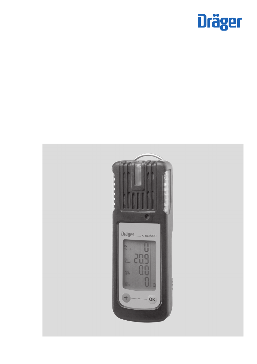
Dräger X-am® 1700, 2000
approved as type LQG 00xx
Multi-Gas Monitor
Technical Manual
ST-7452-2005.eps
Page 2

Content
Content
For Your Safety . . . . . . . . . . . . . . . . . . . . . . . . . . . . . . . . . . . . . . . . . . . . . . . . . . . . . 4
Safety symbols used in these Technical Manual . . . . . . . . . . . . . . . . . . . . . . . . . . . . 4
Intended Use . . . . . . . . . . . . . . . . . . . . . . . . . . . . . . . . . . . . . . . . . . . . . . . . . . . . . . . 5
Tests and Approvals . . . . . . . . . . . . . . . . . . . . . . . . . . . . . . . . . . . . . . . . . . . . . . . . . 6
Marking . . . . . . . . . . . . . . . . . . . . . . . . . . . . . . . . . . . . . . . . . . . . . . . . . . . . . . . . . . . . 6
Intended Operating Area and Operating Conditions . . . . . . . . . . . . . . . . . . . . . . . . . . 7
What is What . . . . . . . . . . . . . . . . . . . . . . . . . . . . . . . . . . . . . . . . . . . . . . . . . . . . . . . 8
Front panel . . . . . . . . . . . . . . . . . . . . . . . . . . . . . . . . . . . . . . . . . . . . . . . . . . . . . . . . . 8
Rear panel . . . . . . . . . . . . . . . . . . . . . . . . . . . . . . . . . . . . . . . . . . . . . . . . . . . . . . . . . 8
Display . . . . . . . . . . . . . . . . . . . . . . . . . . . . . . . . . . . . . . . . . . . . . . . . . . . . . . . . . . . . 8
Special Symbols . . . . . . . . . . . . . . . . . . . . . . . . . . . . . . . . . . . . . . . . . . . . . . . . . . . . . 9
Configuration . . . . . . . . . . . . . . . . . . . . . . . . . . . . . . . . . . . . . . . . . . . . . . . . . . . . . 10
Standard Gas Configuration . . . . . . . . . . . . . . . . . . . . . . . . . . . . . . . . . . . . . . . . . . . 10
Standard Device Configuration on Delivery . . . . . . . . . . . . . . . . . . . . . . . . . . . . . . . 10
Activating the Device . . . . . . . . . . . . . . . . . . . . . . . . . . . . . . . . . . . . . . . . . . . . . . . 11
Operation . . . . . . . . . . . . . . . . . . . . . . . . . . . . . . . . . . . . . . . . . . . . . . . . . . . . . . . . . 12
Switching on the device . . . . . . . . . . . . . . . . . . . . . . . . . . . . . . . . . . . . . . . . . . . . . . 12
Switching off the device . . . . . . . . . . . . . . . . . . . . . . . . . . . . . . . . . . . . . . . . . . . . . . 12
Before entering the workplace . . . . . . . . . . . . . . . . . . . . . . . . . . . . . . . . . . . . . . . . . 13
During operation . . . . . . . . . . . . . . . . . . . . . . . . . . . . . . . . . . . . . . . . . . . . . . . . . . . . 13
Calling the Info Mode . . . . . . . . . . . . . . . . . . . . . . . . . . . . . . . . . . . . . . . . . . . . . . . . 14
Calling the Quick Menu . . . . . . . . . . . . . . . . . . . . . . . . . . . . . . . . . . . . . . . . . . . . . . . 15
Possible functions of the quick menu . . . . . . . . . . . . . . . . . . . . . . . . . . . . . . . . . 15
Calling the Calibration Menu . . . . . . . . . . . . . . . . . . . . . . . . . . . . . . . . . . . . . . . . . . . 16
Calibration menu functions . . . . . . . . . . . . . . . . . . . . . . . . . . . . . . . . . . . . . . . . . 17
Identifying Alarms . . . . . . . . . . . . . . . . . . . . . . . . . . . . . . . . . . . . . . . . . . . . . . . . . . 18
Concentration pre-alarm A1 . . . . . . . . . . . . . . . . . . . . . . . . . . . . . . . . . . . . . . . . . . . 18
Concentration main alarm A2 . . . . . . . . . . . . . . . . . . . . . . . . . . . . . . . . . . . . . . . . . . 18
STEL / TWA exposure alarm . . . . . . . . . . . . . . . . . . . . . . . . . . . . . . . . . . . . . . . . . . 18
Battery pre-alarm . . . . . . . . . . . . . . . . . . . . . . . . . . . . . . . . . . . . . . . . . . . . . . . . . . . 19
Battery main alarm . . . . . . . . . . . . . . . . . . . . . . . . . . . . . . . . . . . . . . . . . . . . . . . . . . 19
Device alarm . . . . . . . . . . . . . . . . . . . . . . . . . . . . . . . . . . . . . . . . . . . . . . . . . . . . . . . 19
End of operation . . . . . . . . . . . . . . . . . . . . . . . . . . . . . . . . . . . . . . . . . . . . . . . . . . . . 19
Pump Operation . . . . . . . . . . . . . . . . . . . . . . . . . . . . . . . . . . . . . . . . . . . . . . . . . . . 20
With Dräger X-am 125 pump . . . . . . . . . . . . . . . . . . . . . . . . . . . . . . . . . . . . . . . . . . 20
With hand pump adapter and rubber ball pump . . . . . . . . . . . . . . . . . . . . . . . . . . . . 20
Observe the following during pump operation mode . . . . . . . . . . . . . . . . . . . . . . . . 20
Configuring the Device . . . . . . . . . . . . . . . . . . . . . . . . . . . . . . . . . . . . . . . . . . . . . . 21
Read Data Base and Display Graphically . . . . . . . . . . . . . . . . . . . . . . . . . . . . . . . 22
2
Page 3

Content
Faults, Cause and Remedy . . . . . . . . . . . . . . . . . . . . . . . . . . . . . . . . . . . . . . . . . . . 23
Warning messages . . . . . . . . . . . . . . . . . . . . . . . . . . . . . . . . . . . . . . . . . . . . . . . . . . 23
Fault messages . . . . . . . . . . . . . . . . . . . . . . . . . . . . . . . . . . . . . . . . . . . . . . . . . . . . . 25
Maintenance . . . . . . . . . . . . . . . . . . . . . . . . . . . . . . . . . . . . . . . . . . . . . . . . . . . . . . . 28
Maintenance intervals . . . . . . . . . . . . . . . . . . . . . . . . . . . . . . . . . . . . . . . . . . . . . . . . 28
Carrying Out the Function Test with Gas (Bump Test) . . . . . . . . . . . . . . . . . . . . . . . 29
Manual implementation without the documentation of result in the device
memory . . . . . . . . . . . . . . . . . . . . . . . . . . . . . . . . . . . . . . . . . . . . . . . . . . . . . . . . 29
Menu implementation with the documen-tation of results in the device memory . 30
Automatic implementation with the Bump Test Station . . . . . . . . . . . . . . . . . . . . 33
Calibrating / Adjusting the Device . . . . . . . . . . . . . . . . . . . . . . . . . . . . . . . . . . . . . . . 35
Carrying out the fresh air calibration . . . . . . . . . . . . . . . . . . . . . . . . . . . . . . . . . . 36
Carry out the 1-button calibration . . . . . . . . . . . . . . . . . . . . . . . . . . . . . . . . . . . . . 38
Calibrating/adjusting the sensitivity for a single measuring channel . . . . . . . . . . 40
Replacing the Batteries / Rechargeable Batteries . . . . . . . . . . . . . . . . . . . . . . . . . . . 42
Charging the Rechargeable Batteries . . . . . . . . . . . . . . . . . . . . . . . . . . . . . . . . . . . . 43
Charging with the multiple charging station . . . . . . . . . . . . . . . . . . . . . . . . . . . . . 43
Charging with charging module and plug-in power pack or vehicle charging
adapter . . . . . . . . . . . . . . . . . . . . . . . . . . . . . . . . . . . . . . . . . . . . . . . . . . . . . . . . . 45
Replacing the Sensors . . . . . . . . . . . . . . . . . . . . . . . . . . . . . . . . . . . . . . . . . . . . . . 46
Care . . . . . . . . . . . . . . . . . . . . . . . . . . . . . . . . . . . . . . . . . . . . . . . . . . . . . . . . . . . . . . 48
Disposing of the Device . . . . . . . . . . . . . . . . . . . . . . . . . . . . . . . . . . . . . . . . . . . . . 49
Technical Data . . . . . . . . . . . . . . . . . . . . . . . . . . . . . . . . . . . . . . . . . . . . . . . . . . . . . 50
Sensor Data . . . . . . . . . . . . . . . . . . . . . . . . . . . . . . . . . . . . . . . . . . . . . . . . . . . . . . . . 50
Order List . . . . . . . . . . . . . . . . . . . . . . . . . . . . . . . . . . . . . . . . . . . . . . . . . . . . . . . . . 52
Accessories . . . . . . . . . . . . . . . . . . . . . . . . . . . . . . . . . . . . . . . . . . . . . . . . . . . . . . . . 53
Spare parts . . . . . . . . . . . . . . . . . . . . . . . . . . . . . . . . . . . . . . . . . . . . . . . . . . . . . . . . 54
Declaration of Conformity . . . . . . . . . . . . . . . . . . . . . . . . . . . . . . . . . . . . . . . . . . . . 55
3
Page 4
For Your Safety
For Your Safety
Strictly follow the Instructions for Use
Any use of the device requires full understanding and strict observation of the Instructions for
Use supplied with the device.
The device is only to be used for the purposes specified here.
Maintenance
The maintenance intervals and measures stated in this Technical Handbook as well as the
specifications in the Instructions for Use of the used DrägerSensors
Repair of the instrument may only be carried out by trained service personnel.
Accessories
Do not use accessory parts other than those listed in the order list.
Safe coupling with electrical devices
Devices which are not mentioned in the Instruction for Use or in this Technical Handbook can
only be coupled electronically after consultation with the manufacturers or an expert.
Use in areas subject to explosion hazards
Devices or components for use in explosion-hazard areas which have been tested and approved according to national, European or international Explosion Protection Regulations may be
used only under the conditions explicitly specified in the approval and with consideration of
the relevant legal regulations. The equipment or components may not be modified in any
manner. The use of faulty or incomplete parts is forbidden. The appropriate regulations must
be observed at all times when carrying out repairs on these devices or components.
Safety symbols used in these Technical Manual
These Technical Manual contain a number of warnings for risks and hazards which might
occur when using the device. These warnings contain signal words to alert you to the degree
of hazard you may encounter. These signal words and corresponding hazards are as follows:
1)
must be observed.
DANGER
Indicates an immediate hazardous situation which, if not avoided, could result in death or
serious injury.
WARNING
Indicates a potential hazardous situation which, if not avoided, could result in death or
serious injury.
1) The Instructions for Use of the DrägerSensors are supplied with the device on CD.
4
Page 5

Intended Use
CAUTION
Indicates a potential hazardous situation which, if not avoided, could result in injury or
damage to property.
Can also be used to warn against any wanton actions.
NOTICE
Additional information on the use of the device.
Intended Use
Portable gas measuring device for the continuous monitoring of the concentration of several
gases in the ambient air in the working area and in explosion-hazard areas.
X-am 1700:
independent measurement of four gases.
X-am 1700: 2 years service life from activation of the device (refer to page 11).
X-am 2000 depending on the device type:
independent measurement of one gas up to four gases.
5
Page 6
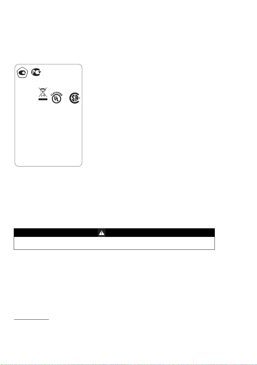
Tests and Approvals
D Type: LQG 0000
Dräger Safety
23560 Lübeck
Germany
DEMKO 06 ATEX 140055X
Um=4.6V Im=1.3A IECEx ULD 06.0001X
Ex ia s Zone 0 I/IIC TC T4/T3 ANZEx 06.3037X
Only as to intrinsic safety for use in haz loc.
Intrinsically safe / Securite Intrinseque Ex ia
Class I&II, Div. 1, Gr.A,B,C,D,E,F,G TC T4/T3
CSA: Class I, Div. 1, Gr.A,B,C,D TC T4/T3
TC & Ambient Temperature: see Battery Pack!
Read manual for safety precautions.
Do not change or charge batteries in haz loc.
I M2 / II 2G
BVS 06 ATEX G 006X PFG 06 G 001
Ex ia d I/IIC T4/T3
-20°C Ta +50/+40°C
Warning:
C 0158
LR97594
9N54
C22.2 No. 152
РОСС ГБ05.DE. B03849
ExdiaIMbX
Ex d ia IIC T4(T3) Gb X
ГБ05
Tests and Approvals
Marking
Power pack 83 18 703;
approved as type ABT 0000
Temperature class T4
o
–20
C ≤ Ta ≤ +50 oC
use with alkaline batteries
Energizer No. E91
Energizer No. EN91 (industrial)
Varta Type 4106 (power one)
Temperature class T3
o
–20
C ≤ Ta ≤ +40 oC
use with NiMH batteries
GP 180AAHC (1800 mAh)
Power pack 83 18 704;
approved as HBT 0000
Temperature class T4
o
–20
C ≤ Ta ≤ +50 oC
Serial no.
1)
WARNING
Read the safety measures in the Instructions for Use.
Do not replace or charge batteries in potentially explosive areas. Danger of explosion!
1) Year of construction is coded by the third capital letter of the serial number: T = 2003, U = 2004, W = 2005,
X = 2006, Y = 2007, Z = 2008, A = 2009, B = 2010, C = 2011, etc.
Example: Serial number ARUH-0054: the third letter is U, so the year of construction is 2004.
6
Page 7
Tests and Approvals
Intended Operating Area and Operating Conditions
Hazardous areas classified by zones
The device is intended to be used in hazardous areas or mines susceptible to firedamp classified zone 1 or zone 2, within a temperature range of –20
(depending on battery pack and batteries), where gases of explosion groups IIA, IIB or IIC
and temperature class T3 or T4 (depending on battery pack and batteries) may be present.
If used in mines, the device is only to be used in areas known to have a low risk of mechanical
impact.
Hazardous areas classified by divisions
The device is intended to be used in hazardous areas or mines susceptible to firedamp classified Class I&II, Div. 1 or Div. 2, within a temperature range of –20
–20oC to +50oC (depending on battery pack and batteries), where gases or dusts of groups
A, B, C, D or E, F, G and temperature class T3 or T4 (depending on battery pack and batteries) may be present.
o
C to +50 oC or –20 oC to +50oC
o
C to +50 oC or
Safety Instructions
WARNING
To reduce the danger of explosion, do not mix new batteries with old batteries and do not
mix batteries made by different manufacturers.
WARNING
Always disconnect the device from the power pack before carrying out any maintenance
operations.
WARNING
Substitution of components may impair intrinsic safety.
CAUTION
Not tested in an oxygen-enriched atmosphere (>21 % O2).
Only the combustible gas detection portion of this instrument has been assessed for performance.
WARNING
High off-scale readings may indicate an explosive concentration.
WARNING
Before each day's usage sensitivity must be tested on a known concentration of the gas to
be detected equivalent to 25 to 50% of full scale concentration. Accuracy must be within
0 to +20% of the actual value. Accuracy may be corrected by calibration.
7
Page 8
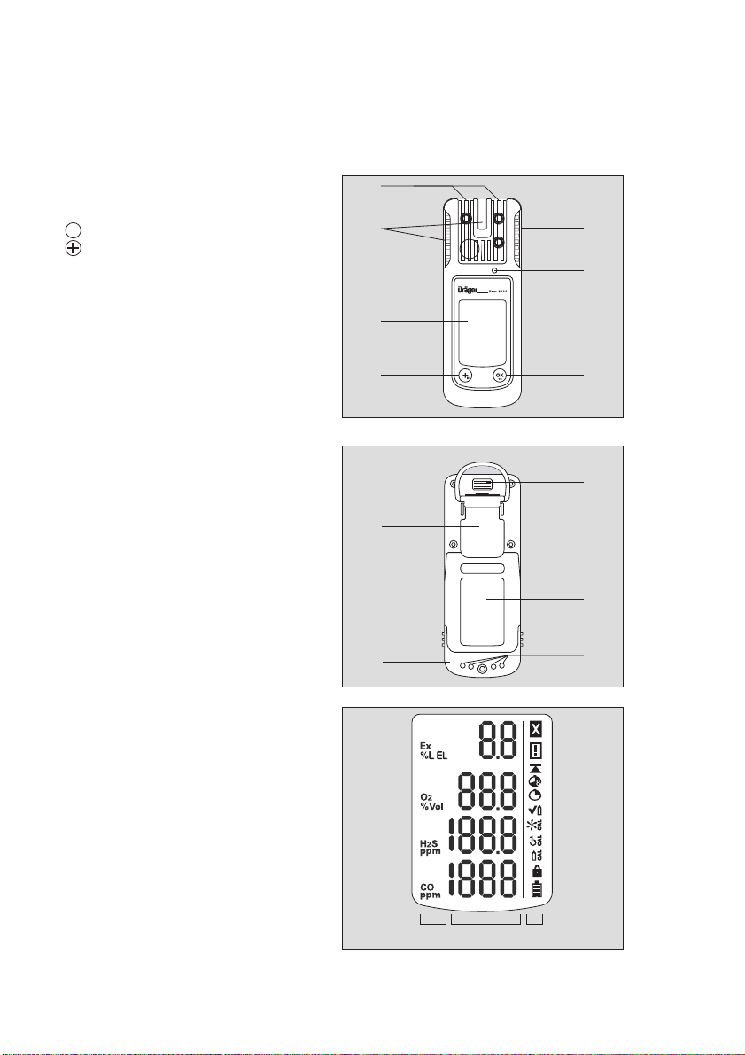
What is What
00223854_01.eps
0
1
2
6
5
4
3
2
OK
00323854_01.eps
2
1
4
3
5
00423854_01_en.eps
123
What is What
Front panel
1 Gas entry
2 Alarm LED
3 Buzzer
4 key
5 key
6 Display
Rear panel
1 IR interface
2 Fastening clip
3 Type plate
4 Charging contacts
5 Power pack
Display
1 Measured gas display
2 Measured value display
3 Special symbols
8
Page 9

Special Symbols
Fault message, refer to page 14
Warning message, refer to page 14
The peak value display for all measuring gases, refer to page 14
What is What
The exposure evaluation display (TWA) for measuring gas H
refer to page 14
S and CO,
2
The exposure evaluation display (STEL) is switched on for measuring rangasge H
and CO, refer to page 14
The device is set to function test with gas (bump test),
refer to page 29
The device is set to the fresh air calibration function,
refer to page 36
The device is set to the 1-button calibration function,
refer to page 38
The device is set to the single-gas calibration function,
refer to page 40
The function for password entry is active, refer to page 16
Battery / rechargeable battery 100 % full
Battery / rechargeable battery 2/3 full
Battery / rechargeable battery 1/3 full
Battery / rechargeable battery empty
S
2
9
Page 10
Configuration
Configuration
Standard Gas Configuration
DrägerSensor CatEx
125 PR
[%LEL]
Measuring range
Alarm A1
- setpoint
- can be acknowledged
- self-latching
Alarm A2
- setpoint
- can be acknowledged
- self-latching
2)
2)
0 to 100 0 to 25 0 to 2000 0 to 100
20
yes
no
2)
40
no
yes
Standard Device Configuration on Delivery
XXS O
[Vol.-%]
1)
19
no
yes
23
no
yes
2
XXS CO
XXS H2S LC
[ppm]
30
yes
no
60
no
yes
X-am 1700 / X-am 2000
[ppm]
10
yes
no
20
no
yes
Function test with gas (bump test) in
Quick Menu
2)
Fresh air calibration in Quick Menu
Life sign
Switch off
LEL factor
2)
2)
2)
2)
4.4 (4.4 vol. % corresponds to 100 %LEL)
Quick bump test
off
on
allowed
(CH4)
Averaging time
2)
15 minutes for STEL
8 hours for TWA
Changing the standard configuration: See “Configuring the Device” on page 21.
WARNING
After a basic initialization has been carried out with the PC software Dräger CC Vision, individual alarm settings may have been changed.
___________________
1)
In the case of O2 A1 is the lower alarm setpoint: an alarm is issued if the value is too low.
2)
Different settings can be selected to meet customer requirements on delivery. The current setting can
be checked and changed with the software "CC Vision".
A version of Dräger CC-Vision which can be used for Dräger X-am 1700/2000 is supplied with the
device on CD.
10
Page 11
Activating the Device
02223854_01_de.eps
OK
Before using the device for the first time,
insert the supplied batteries or a charged
NiMH power pack T4 (order no. 83 18 704),
refer to Replacing the Batteries, page 42.
Charge the rechargeable batteries if necessary, page 43.
The Dräger X-am 2000 is ready for operation.
Only in the case of Dräger X-am 1700:
The following activation sequence also has
to be carried out:
● Press and hold the key for approx. 3
seconds until the countdown »3.2.1«
shown in the display has elapsed.
— The remaining operating time is dis-
played, e.g. » d 730 « (remaining operating time 730 days).
— After that, the device is automatically
switched off again. You can switch it on
again at any time by pressing the key.
Activating the Device
11
Page 12

Operation
OK
OK
Operation
Switching on the device
● Press and hold the key for approx. 3 seconds until the countdown »3.2.1« shown
in the display has elapsed.
— All the display segments, including the visual, audible and vibration alarms, are activated
for a short time.
— The software version is displayed.
— The device performs a self test.
— The remaining operating time is displayed, e.g. »d730« (remaining operating time
730 days). This applies to Dräger X-am 1700 and if the service life is activated in Dräger
X-am 2000.
— All alarm setpoints A1 and A2 as well as » « (TWA)
and CO are displayed in succession.
— The time until the calibration interval expires is displayed in days, e.g. » CAL 73 «.
— The sensor which is next due for calibration/adjustment is displayed with the days remai-
ning until the next calibration/adjustment e.g. » Ex %UEG CAL 20 «.
— During the warm-up time of the sensors, the respective display of the measured value flas-
hes and the special symbol » « (for warning) is displayed. No alarms are issued during
the running-in period of the sensors.
● Press the key to cancel the display of the activation sequence.
Switching off the device
● Press and hold the key and the key at the same time until the countdown
»3.2.1« shown in the display has elapsed.
— Before the device is switched off, the visual, audible and vibration alarms are activated for
a short time.
OK
1)
and » « (STEL)*) for H2S
1) Nur wenn in Gerätekonfiguration aktiviert. Auslieferungszustand: nicht aktiviert.
12
Page 13
Operation
Before entering the workplace
CAUTION
Check and, if necessary, adjust the calibration before carrying out safety-relevant measurements. A function test with gas (bump test) must be carried out in accordance with local
regulations.
● Switch on the device. The current measured values are shown in the display.
● Observe any warning » « or fault » « messages.
The device can be operated normally. If the warning message does not go out automatically during operation, the device must be maintained after the end of use.
The device is not ready to measure and requires maintenance.
If one of these special symbols is displayed, appropriate measures, refer to page 23 to
page 25, must be taken.
● Check that the gas inlet opening on the device is not covered.
WARNING
The presence of catalyst poisons in the measured gas (e.g., volatile silicone, sulfur, heavy
metal compounds or halogenated hydrocarbons) can damage the DrägerSensor CatEx
125 PR. If the sensor cannot be calibrated to the target concentration anymore, the sensor
must be replaced. The display of the CatEx 125 PR sensor may be incorrect in an oxygenpoor atmosphere. Electrical operating safety (Ex protection) is not guaranteed in an oxygenenriched atmosphere. Danger of explosion!
During operation
During operation, the measured values for every measured gas are displayed.
If a measuring range is exceeded or a negative drift occurs, the following displays are shown
instead of the measured value display:
» « (too high concentration) or » « (negative drift).
— If the concentrations of combustible materials are too high, this may result in a lack
of oxygen.
— If the O
In the event of an alarm, the corresponding displays, including the visual, audible and vibration alarms are activated – refer to “Identifying Alarms” on page 18.
When the measuring range on the CatEx channel is significantly exceeded (very high concentration of flammable substances), a latching alarm is triggered. This CatEx latching alarm is
acknowledged either automatically by a functioning (i.e. free of warnings and malfunctions)
oxygen channel or by manually switching the unit off and on again in fresh air.
concentrations are under 8 vol. %, a fault with » « is displayed for the
2
Ex channel instead of the measured value, if the measurement is below the pre-alarm
threshold.
WARNING
After exposition to concentrations above 100 %LEL, the indication displayed at the CatEx
channel may be incorrect. Before any further use of the device within the concentration
range from 0 to 100 %LEL, check and, if necessary, adjust the zero point and the sensitivity.
After the measuring range of the TOX measuring channels has been exceeded temporarily
(up to one hour), checking the measuring channels is not necessary.
When using a CatEx sensor in the Dräger X-am 2000, the zero point and sensitivity must be
adjusted after any extreme impact loading.
13
Page 14

Operation
OK
OK
OK
OK
OK
Calling the Info Mode
● In measuring mode, press the key for approx. 3 seconds.
1)
Any information and fault codes, the peak values as well as the TWA
values are displayed in succession (press the key for the next display). If any warning or
fault messages exist, the corresponding note or error codes are displayed (page 23 to
page 27).
Warning messages are displayed. Numerical codes of the warning messages: see
page 23.
and STEL*) exposure
⇓ -key
Fault messages are displayed. Numerical codes of the fault messages: see
page 25.
⇓ -key
The peak values = the maximum measured values in the case of e.g. CO, H
or the minimum measured values in the case of O
displayed
OK
⇓ key
The average values of the exposures based on a shift of e.g. 8 hours (TWA) of all
the active sensors for the exposure evaluation are displayed
OK
⇓ key
The short-term values (STEL) = average values of the concentrations over the
average value duration of all the active sensors for the exposure evaluation are
displayed
within the storage interval are
2
S, ...
2
⇓ key
The device is in measuring mode again
— If no key is pressed for 10 seconds, the device returns automatically to measuring mode.
1) Only when activated in the device configuration. Delivery status: not activated.
14
Page 15

Operation
Calling the Quick Menu
— If functions were activated for the quick menu with the PC software "CC Vision"
(no functions are activated in the quick menu on delivery):
● In measuring mode, press the key three times.
If no functions have been activated in the quick menu, the device remains in measuring
mode.
— You can select the activated functions of the quick menu by pressing the key.
● Press the key to call the selected function.
Possible functions of the quick menu
● Press the key to cancel the active function and to switch to measuring mode.
— If no key is pressed for 60 seconds, the device returns automatically to measuring mode.
OK
Function test with gas (bump test), refer to page 29
Fresh air calibration, refer to page 36
15
Page 16
Operation
OK
OK
OK
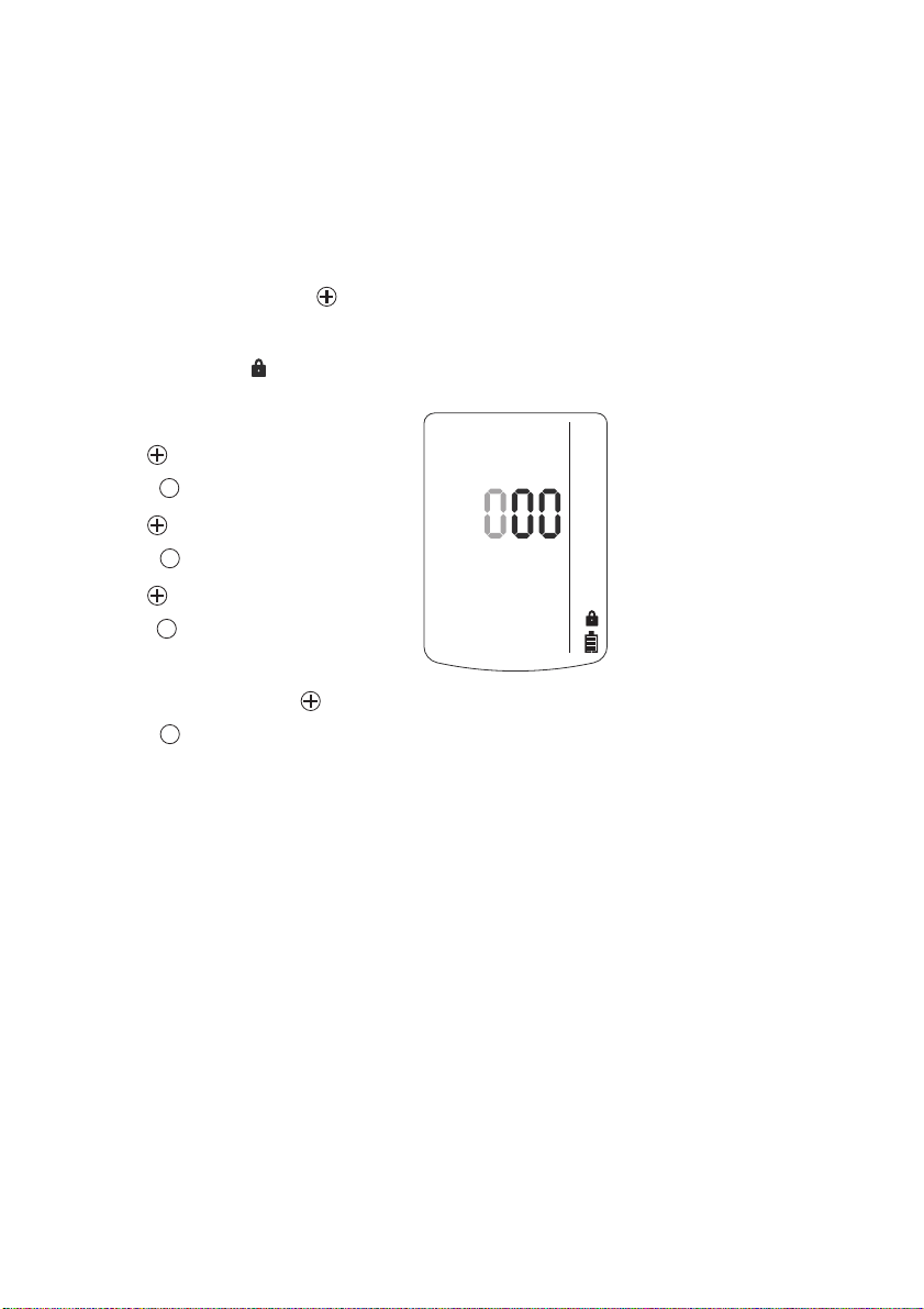
Calling the Calibration Menu
— The calibration menu can only be ac-
cessed by entering a password.
Password on delivery: » 001 «
— The default password on delivery can be
changed using the PC software "CC Vision".
● In measuring mode, press the key for
at least 5 seconds.
— The function for entering the password is
selected.
— The special symbol » « (for the "enter
password" function) is displayed.
— The display shows » 000 « with the first
digit flashing.
● Use the key to set the flashing digit.
● Press the key, the second digit starts
flashing.
● Use the key to set the flashing digit.
● Press the key, the third digit starts
flashing.
● Use the key to set the flashing digit.
● Press the key to confirm the password
once it has been set completely.
— The calibration menu functions can now
be selected by pressing the key.
● Press the key to call the selected
function.
OK
02323854_01.eps
16
Page 17

Operation
Calibration menu functions
Fresh air calibration, refer to page 36
1-button calibration, refer to page 38
Single gas calibration, refer to page 40
● Press the key to cancel the active function.
— If no key is pressed for 10 minutes, the device returns automatically to measuring mode.
17
Page 18

Identifying Alarms
OK
OK
OK
Identifying Alarms
An alarm is displayed visually, audibly and through vibration in a specific pattern.
Concentration pre-alarm A1
The alarm is indicated by an intermittent alarm message:
Display »A1« and measured value alternating: not for O
— The pre-alarm A1 is not self-latching and stops when the concentration has dropped below
the alarm setpoint A1.
— In the case of A1 a single tone is audible and the alarm LED flashes.
Acknowledging a pre-alarm:
● Press the key. Only the audible alarm and the vibration alarm are switched off.
Concentration main alarm A2
The alarm is indicated by an intermittent alarm message:
Display »A2« and measured value alternating:
In the case of A2 a double tone is audible and the alarm LED flashes twice.
: »A1« and measurement value alternating = oxygen deficiency
For O
2
» A2 « and measurement value alternating = oxygen surplus
DANGER
Leave the area immediately. Danger to life! A main alarm is self-latching
and cannot be acknowledged or cancelled.
After leaving the area, if the concentration is less than the alarm setpoint A2:
● Press the key. The alarm messages are switched off.
● A latching alarm on the CatEx channel (due to the measuring range being significantly ex-
ceeded) cannot be acknowledged by the key. The CatEx latching alarm is acknowledged either automatically by a functioning (i.e. free of warnings and malfunctions) oxygen
channel or by manually switching the unit off and on again in fresh air.
!
2
STEL / TWA exposure alarm
The alarm is indicated by an intermittent alarm message:
Display »A2« and »« or »« and measured value alternating:
CAUTION
Leave the area immediately. After this alarm, the deployment of personnel
is subject to the relevant national regulations.
— The STEL and TWA alarm cannot be acknowledged or cancelled.
● Switch off the device. The values for the exposure evaluation are deleted after the device
is switched on again.
18
Page 19

Identifying Alarms
OK
Battery pre-alarm
The alarm is indicated by an intermittent alarm message:
Flashing special symbol »« on the right side of the display:
Acknowledging the pre-alarm:
● Press the key. Only the audible alarm and the vibration alarm are switched off.
— The battery still lasts approx. 20 minutes after the first battery pre-alarm.
OK
Battery main alarm
The alarm is indicated by an intermittent alarm message:
Flashing special symbol »« on the right side of the display:
The battery main alarm cannot be acknowledged or cancelled:
— The device is automatically switched off again after 10 seconds.
— Before the device is switched off, the visual, audible and vibration alarms are activated for
a short time.
Device alarm
Intermittent alarm message:
Special symbol » « on the right side of the display:
— The device or one or several sensor channels are not ready for operation.
— For remedies, refer to page 23 to page 25.
● If necessary, commission the Dräger Safety Service Center to eliminate the error.
End of operation
Only in the case of X-am 1700.
A warning period starts before the end of the operating time.
— After switching on the device, the special symbol » « (for warning) is displayed.
Acknowledging the end of operation warning:
● Press the key. The device will continue to operate until the operating time has elapsed.
— When the operating time has elapsed, the text »d0« flashes. The device cannot be swit-
ched on anymore.
19
Page 20

Pump Operation
Pump Operation
With Dräger X-am 125 pump
Accessories:
Dräger X-am 125 pump, sampling hose and probes, see Order List, see “Accessories” on
page 53
Commissioning and performing the measurement:
● see the Instructions for Use of the Dräger X-am 125.
With hand pump adapter and rubber ball pump
Accessories:
Hand pump adapter, rubber ball pump, sampling hose and probes, see Order List, see
“Accessories” on page 53.
Commissioning and performing the measurement:
● see the Instructions for Use of the used accessories.
Observe the following during pump operation mode
● The required waiting time when flushing the extension hose or probes.
Prior to every measurement, flush the Dräger sampling hose or the Dräger probes with the
air sample to be measured.
— It is absolutely necessary to flush the extension hose for a period of time to eliminate or
minimize the effects which may interfere with measurements when using a sampling hose
or a probe, e.g. memory effects, dead volume.
— The flushing time depends on various factors e.g. type and concentration of the gas or va-
por to be measured, material, length, diameter and age of the sampling hose or the probe.
Generally, when using a sampling hose (new, dry, clean), a typical flushing time of approx.
3 seconds is required per meter. This flushing time applies in addition to the sensor response time (see the Instructions for Use of the used gas measuring device).
Example:
— In the case of a 10 m long sampling hose, the flushing time is approx. 30 seconds and the
sensor response time is in addition approx. 60 seconds. Hence, the total time required to
read the gas measuring device is approx. 90 seconds.
— The flow rate alarm is delayed depending on the length of the hose by 10 to 30 seconds.
20
Page 21

Configuring the Device
p
Configuring the Device
To individually configure a device with standard configuration, the device must be connected
with a PC.
0
IR
USB 1.1
Dräger
CC-Vision
USB DIRA with USB cable
(order no. 83 17 409)
0
USB 1.1
Dräger
CC-Vision
Calibration cradle (order no. 83 18 752)
with inserted
USB DIRA with USB cable (order no. 83 17 409)
0
USB 1.1 / COM
Dräger
CC-Vision
E-Cal module Dräger X-am 125
(order no. 83 18 754)
The installed PC software "CC Vision" is used for configuration.
● Observe the documentation and online help of the software.
— A version of Dräger CC Vision which can be used for X-am 1700/2000 is supplied with the
device on CD.
s
01423854_01_en.e
21
Page 22

Read Data Base and Display Graphically
IR
Calibration cradle (order no. 83 18 752)
with inserted
USB DIRA with USB cable (order no. 83 17 409)
USB DIRA with USB cable
(order no. 83 17 409)
E-Cal module Dräger X-am 125
(order no. 83 18 754)
USB 1.1
USB 1.1
USB 1.1 / COM
01823854_01_en.eps
Dräger
GasVision
Dräger
GasVision
Dräger
GasVision
0
0
0
Read Data Base and Display Graphically
To read the data base of the device and display it graphically, the device must be connected
with a PC.
The installed PC software "GasVision" is used for reading and displaying the data base.
● Observe the documentation and online help of the software.
22
Page 23

Faults, Cause and Remedy
Faults, Cause and Remedy
Fault Cause Remedy
Not possible to switch on the
device
Not possible to switch off the
device
Display »–––« Measuring range calibrated
To display the numerical codes of the warning and fault messages in the info mode, see
page 14.
Warning messages
Special symbol » « and
displayed numerical code:
151 Service life of device about to
152 Customer's service life coun-
Discharge the power pack Charge the power pack,
Discharge the alkaline batteries
The device is not set to
measuring mode
The device is configured to
"Disable prohibited"
incorrectly
Electronics or sensors defective
Cause Remedy
elapse
ter about to elapse
page 43.
Insert new alkaline batteries,
page 42.
Select measuring mode.
Configure the device to
"Disable allowed" with "CC
Vision".
Recalibrate the measuring
range, page 35.
Must be repaired by DrägerService.
Procure follow-on device.
Reset the service life counter
using "CC Vision".
153 Data base 90% full Read the data base soon and
154 Data base full Read the data base and clear
155 Interval for the function test
159 Calibration not possible.
251 DrägerSensor CatEx 125 PR
252 DrägerSensor CatEx 125 PR
with gas (bump test) elapsed
The menu function cannot be
carried out because of a message which is preventing the
function (e.g. sensors in
warm-up phase).
in warm-up phase
in warm-up phase
clear memory afterwards.
memory.
Carry out the function test,
page 29.
Determine the message code
via the info menu and switch it
off, if necessary.
Wait until warm-up time is
complete.
Wait until warm-up time is
complete.
23
Page 24

Faults, Cause and Remedy
Special symbol » « and
displayed numerical code:
253 Ex concentration has drifted
Cause Remedy
into the negative range
Carry out the fresh air calibration, page 36.
254 The temperature is too high Operate the device within the
allowed temperature range.
255 The temperature is too low Operate the device within the
256 The calibration interval for
257 Alarm setpoint A2 setting is
351 DrägerSensor XXS O
352 DrägerSensor XXS O
353 O
DrägerSensor CatEx 125 PR
has elapsed
greater than 60 %LEL
warm-up phase
warm-up phase
concentration drifted into
2
the negative range
2
2
354 The temperature is too high Operate the device within the
allowed temperature range.
Carry out the span calibration
for DrägerSensor CatEx
125 PR, page 40.
Set alarm setpoint to less than
60 % LEL.
in the
Wait until warm-up time is
complete.
in the
Wait until warm-up time is
complete.
Fresh air calibration required,
page 36.
allowed temperature range.
355 The temperature is too low Operate the device within the
allowed temperature range.
356 The calibration interval for
DrägerSensor XXS O
elapsed
2
Carry out the span calibration
has
for DrägerSensor XXS O2,
page 40.
451 DrägerSensor XXS H
warm-up phase
452 DrägerSensor XXS H
453 H
warm-up phase
S concentration has drifted
2
into the negative range
S in the
2
S in the
2
Wait until warm-up time is
complete.
Wait until warm-up time is
complete.
Carry out the fresh air calibration, page 36.
454 The temperature is too high Operate the device within the
allowed temperature range.
455 The temperature is too low Operate the device within the
allowed temperature range.
456 The calibration interval for
551 DrägerSensor XXS CO in the
DrägerSensor XXS H
elapsed
warm-up phase
2
Carry out the span calibration
S has
for DrägerSensor XXS H2S,
page 40.
Wait until warm-up time is
complete.
24
Page 25

Faults, Cause and Remedy
Special symbol » « and
displayed numerical code:
552 DrägerSensor XXS CO in the
553 CO concentration has drifted
554 The temperature is too high Operate the device within the
555 The temperature is too low Operate the device within the
556 The calibration interval for
Cause Remedy
warm-up phase
into the negative range
DrägerSensor XXS CO has
elapsed
Wait until warm-up time is
complete.
Carry out the fresh air calibration, page 36.
allowed temperature range.
allowed temperature range.
Carry out the span calibration
for DrägerSensor XXS CO,
page 40.
Fault messages
Special symbol »«
and displayed numerical
code:
101 The service life of the device
102 The customer's service life
103 The device is defective The device must be repaired by
104 Check sum error program
105 Update error The device must be repaired by
106 Check sum error data Reconfigure the device with "CC
107 Failed visual inspection or
108 The data base is defective Execute the menu function
109 The menu function cannot be
201 The zero point calibration of
Cause Remedy
has elapsed
counter has elapsed
code
alarm element test
carried out because of an
error.
the DrägerSensor CatEx
125 PR is not valid
Return the device to Dräger
Safety to be disposed.
Reset the service life counter
using "CC Vision".
DrägerService.
The device must be repaired by
DrägerService.
DrägerService.
Vision", otherwise return device
to DrägerService.
Repeat visual inspection and
alarm element test with X-dock.
again; otherwise the device must
be repaired by DrägerService.
Determine the error code via the
info menu and switch it off, if
necessary.
Carry out the fresh air calibration, page 36.
25
Page 26

Faults, Cause and Remedy
Special symbol »«
and displayed numerical
Cause Remedy
code:
202 The span calibration of the
DrägerSensor CatEx 125 PR
Carry out the span calibration,
page 38 or page 40.
is not valid
203 The measurement value of the
DrägerSensor CatEx 125 PR
Carry out the fresh air calibration, page 36.
is in the negative range
204 The DrägerSensor CatEx
205 Error during the function test
125 PR is not inserted
with gas (bump test) of the
DrägerSensor CatEx 125 PR
206 Function not possible:
O
deficiency
2
Check the DrägerSensor CatEx
125 PR, page 46.
Repeat the function test, calibrate or replace the
DrägerSensor CatEx 125 PR, if
necessary, page 46.
Use DrägerSensor CatEx
125 PR in atmospheres with
more than 10.0 % O2 by vol..
207 Failed filter test. Repeat filter test with X-dock.
208 Failed rise time test. Repeat rise time test with X-dock.
301 The zero point calibration of
DrägerSensor XXS O
valid
2
302 The span calibration of the
DrägerSensor XXS O
valid
303 O
304 The DrägerSensor XXS O
concentration drifted into
2
the negative range
not inserted
2
Carry out the fresh air calibra-
is not
tion, page 36.
Carry out the span calibration.
is not
page 40 or carry out the fresh air
calibration, page 36.
Fresh air calibration required,
page 36.
is
Check the DrägerSensor XXS
2
O2, page 46.
305 Error during the function test
with gas (bump test) of the
DrägerSensor XXS O
2
Repeat the function test, calibrate or replace the DrägerSensor XXS O
if necessary, page 46.
2
307 Failed filter test. Repeat filter test with X-dock.
308 Failed rise time test. Repeat rise time test with X-dock.
401 The zero point calibration of
DrägerSensor XXS H
valid
S is not
2
402 The span calibration of the
DrägerSensor XXS H
valid
S is not
2
Carry out the fresh air calibration, page 36.
Carry out the span calibration,
page 40.
26
Page 27

Faults, Cause and Remedy
Special symbol »«
and displayed numerical
Cause Remedy
code:
403 Measured value of the Dräger-
Sensor XXS H2S is in the
Carry out the fresh air calibration, page 36.
negative range
404 DrägerSensor XXS H
405 Error during the function test
inserted
with gas (bump test) of the
DrägerSensor XXS H
S is not
2
S
2
Check DrägerSensor XXS H2S,
page 46.
Repeat the function test, calibrate or replace the
DrägerSensor XXS H2S, if
necessary, page 46.
407 Failed filter test. Repeat filter test with X-dock.
408 Failed rise time test. Repeat rise time test with X-dock.
501 The zero point calibration of
the DrägerSensor XXS CO is
Carry out the fresh air calibration, page 36.
not valid
502 The span calibration of the
DrägerSensor XXS CO is not
Carry out the span calibration,
page 40.
valid
503 The measured value of the
DrägerSensor XXS CO is in
Carry out the fresh air calibration, page 36.
the negative range
504 The DrägerSensor XXS CO is
505 Error during the function test
not inserted
with gas (bump test) of the
DrägerSensor XXS CO
Check the DrägerSensor XXS
CO, page 46.
Repeat the function test, calibrate or replace the DrägerSensor XXS CO, if necessary,
page 46.
507 Failed filter test. Repeat filter test with X-dock.
508 Failed rise time test. Repeat rise time test with X-dock.
27
Page 28

Maintenance
Maintenance
Maintenance intervals
The device should be inspected and maintained by suitably qualified persons every six
months (consult: EN 60079-29-2 – Gas measuring device - Selection, installation, use and
maintenance of apparatus for the measurement of combustible gases or oxygen, EN 45544-4
– Electrical apparatus used for the direct detection and direct concentration measurement of
toxic gases and vapours - Part 4: Guide for selection, installation, use and maintenance and
national regulations). We recommend that you calibrate all channels after 6 months.
● Depending on device configuration:
Replace the alkaline batteries or charge the battery – refer to page 42 to page 43 – after
each use, at the latest after the battery alarm has been triggered or after 2 weeks.
● Device calibration – page 35.
— In regular intervals, according to the used sensors and the operating conditions. For sen-
sor-specific calibration data, refer to the Instructions for Use of the used sensors
— Before you carry out safety-related relevant measurements, the zero point and sensitivity
of the devices should be tested in accordance with national regulations.
● Inspection by suitably qualified persons – every year.
— The inspection intervals must be established in each individual case and shortened if ne-
cessary, depending on technical safety considerations, engineering conditions and the
technical requirements of the equipment.
— We recommend that a service agreement be concluded with Dräger Safety and that re-
pairs also be carried out by them.
● Replace the sensors, page 46 – if necessary, when it is not possible to calibrate the sensors anymore.
1)
.
1) The Instructions for Use of the used sensors are supplied with the device on CD.
28
Page 29

Carrying Out the Function Test
0.5 L/min
0
with Gas (Bump Test)
Manual implementation without the documentation of result in the device memory
● Prepare a test gas cylinder, the volume
flow must be 0.5 L/min and the gas concentration must be higher than the alarm
setpoint concentration to be tested.
Example test gas cylinder 68 11 130 =
mixed gas with 50 ppm CO, 15 ppm H
2.5 vol. % CH4, 18 vol. % O
● Connect the test gas cylinder with the calibration cradle (83 18 752).
● Vent the test gas into a fume cupboard or
into the open air (with a hose connected
to the second connector of the calibration
cradle).
2
CAUTION
Do not inhale the test gas. Risk to health!
Observe the hazard warnings of the relevant Safety Data Sheets.
● Switch on the device and insert it into the
calibration cradle – press downwards until it engages.
● Open the test gas cylinder valve to let test
gas flow over the sensors.
● Wait until the device displays the test gas
concentration with sufficient tolerance –
Ex: 40 %LEL ... 74 %LEL
O2: 17.4 vol.-% ... 18.6 vol.-%
H2S: 12 ppm ... 18 ppm
CO: 40 ppm ... 60 ppm
If the alarm setpoints are exceeded, the
device displays the gas concentration in
alternation with »A1« or »A2« depen-
ding on the test gas concentration.
● Close the test gas cylinder valve and remove the device from the calibration cradle.
— If the concentration has now fallen under
the A1 alarm setpoint:
● Acknowledge the alarm.
● If the displays are outside of the
above-mentioned ranges:
● Calibrating the device, refer to page 35.
1)
1)
1)
S,
2
1)
Maintenance
____________
1) Upon application of the Dräger mixed gas (order no. 68 11 130), the displays should be in this range.
Different concentrations can be adjusted using the enclosed software Dräger CC Vision.
29
Page 30

Maintenance
Menu implementation with the documen-tation of results in the device
memory
The "Quick bump test" or the "Extended
bump test" is selected using the Dräger CC
Vision PC software. The "Quick bump test"
checks whether the gas concentration has
exceeded the Alarm 1 threshold (with oxygen, the check is whether the concentration
has fallen below the Alarm 1 threshold). The
"Extended bump test" checks whether the
gas concentration has exceeded the Alarm 1
threshold (with oxygen, the check is whether
the concentration has fallen below the Alarm
1 threshold) and whether the gas concentration has reached the preset bump test concentration.
Setting on delivery: Quick bump test.
● Prepare a test gas cylinder, the volume
flow must be 0.5 L/min and the gas concentration must be higher than the alarm
setpoint concentration to be tested.
Example test gas cylinder 68 11 130 =
mixed gas with 50 ppm CO, 15 ppm H
2.5 vol. % CH4, 18 vol. % O
● Connect the test gas cylinder with the calibration cradle (83 18 752).
● Vent the test gas into a fume cupboard or
into the open air (with a hose connected
to the second connector of the calibration
cradle).
2
S,
2
●
CAUTION
Do not inhale the test gas. Risk to health!
Observe the hazard warnings of the relevant Safety Data Sheets.
0.5 L/min
● Switch on the device and insert it into the
calibration cradle – press downwards until it engages.
● Call the quick menu and select the function test with gas (bump test), page 15.
30
0
00523854_01_en.eps
Page 31

— The current gas concentration values and
OK
_
_
p
02623854_01_en.eps
the special symbol » « (for bump test)
flash.
● Press the key to start the function test
with gas.
● Open the test gas cylinder valve to let test
gas flow over the sensor.
— If gas concentration exceeds the alarm
thresholds A 1 or A 2 the corresponding
alarm will occur.
Exit the function test with gas:
For the manual bump test:
After the set bump test concentration is
reached:
● Press the key.
— The display containing the current gas
concentration changes with the display
»OK«.
— The bump test that was carried out is do-
cumented with the result and date in the
device memory.
● Close the test gas cylinder valve and remove the device from the calibration cradle.
— If the concentration values have now fal-
len under the A1 alarm setpoints, the de-
OK
vice returns to the measuring mode.
— If during the function test no alarm occurs
within 1 minute and the gassing test was
not confirmed by pressing OK, the alarm
mode is activated to indicate failure.
— The fault message » « appears and
» « is displayed instead of the
measured value on the faulty measuring
channel.
● In this case, repeat the function test with
gas or calibrate the device, page 35.
Maintenance
02423854_01_en.eps
s
en.e
01
02523854
31
Page 32

Maintenance
_
_
p
_
_
p
For the automatic bump test:
After the set bump test concentration is
reached:
— The display containing the current gas
concentration changes with the display
»OK«.
— The bump test that was carried out is do-
cumented with the result and date in the
device memory.
● Close the test gas cylinder valve and remove the device from the calibration cradle.
— If the concentration values have now fal-
len under the A1 alarm setpoints, the device returns to the measuring mode.
— If during the function test no alarm occurs
within 1 minute, the alarm mode is activated to indicate failure.
— The fault message » « appears and
» « is displayed instead of the
measured value on the faulty measuring
channel.
● In this case, repeat the function test with
gas or calibrate the device, page 35.
The function test with gas can also be carried
out automatically.
The "Bump Test Station" is required for this
function, refer to page 33.
s02623854
en.e
01
02523854
s
en.e
01
32
Page 33

Maintenance
_
_
p
Automatic implementation with the Bump Test Station
Prerequisite:
The device must first be configured for the automatic function test with gas (bump test) using
the PC software "CC Vision".
— Activate the device for the automatic function test.
— Composition of test gas (mixed gas) – standard on delivery: 50 ppm CO, 15 ppm H
vol. % CH
— Define which measuring channels should participate in the automatic function test. By de-
fault, all measuring channels participate in the function test.
, 18 vol. % O
4
2
● Prepare the Bump Test Station according to the instructions.
● Switch on the device and insert it into the receptacle of the Bump Test Station until it locks
into place.
S, 2.5
2
0
— The function test with gas is started auto-
matically. The special symbol » « (for
bump test) flashes.
— If the gas concentration exceeds the
alarm setpoint A 1 or A 2, the relevant
alarm is triggered, which is automatically
acknowledged after approx. 10 seconds.
Next:
— The display of the current gas concentra-
tion changes with the display »OK«.
The bump test that was carried out is documented with the result and date in the
device memory.
33
03823854_01.eps
s
en.e
01
02523854
Page 34

Maintenance
_
_
p
● Remove the device from the Bump Test
Station.
— If the concentration values have now fal-
len under the A1 alarm setpoints, the device returns to the measuring mode.
— If during the function test no alarm occurs
and the current measured values do not
reach the set target concentration, the error alarm is activated to indicate failure.
— The fault message » « appears and
» « is displayed instead of the
measured value on the faulty measuring
channel.
● In this case, repeat the function test with
gas or calibrate the device, page 35.
s
en.e
01
The function test with gas can also be carried
out manually, refer to page 29 and page 30.
02623854
34
Page 35

Maintenance
Calibrating / Adjusting the Device
Calibration may not be possible due to device and channel errors.
Allow the sensors to warm up before the calibration / adjustment!
Warm-up time: refer to the Instructions for Use of the installed DrägerSensors (on CD).
Calibration interval:
— Observe the relevant specifications in the Instructions for Use of the installed DrägerSen-
sors.
— For critical applications, observe the recommendations in EN 60079-29-2
EN 45544-42) and national regulations. We recommend that you calibrate all channels after 6 months.
CAUTION
Do not inhale the test gas. Risk to health!
Observe the hazard warnings of the relevant Safety Data Sheets.
— Improve the zero point accuracy – carry out the fresh air calibration, page 36.
— Set the sensitivity of all sensors to the value of the test gas – carry out the 1-button cali-
bration, page 38.
— Set the sensor sensitivity to a value of the test gas – calibrate/adjust the sensitivity,
page 40.
1)
or
1) EN 60079-29-2 – Gas measuring device - Selection, installation, use and maintenance of apparatus
for the measurement of combustible gases or oxygen.
2) EN 45544-4 – Electrical devices for the direct detection and direct concentration measurement of toxic
gases and vapours – Part 4: Guidelines for selection, installation, use and maintenance.
35
Page 36

Maintenance
OK
Carrying out the fresh air calibration
To improve the zero point accuracy, you can
carry out a fresh air calibration.
— Calibrate the device to fresh air, free of
measured gases or other interfering gases.
— All the sensors are included in the fresh
air calibration. Sensors which have not
warmed up or which are faulty prevent a
calibration.
In the case of sensors which are in the
warm-up phase, the message » 159 « is
displayed with the special symbol » «
(for warning message).
In the case of a sensor or device error,
the message » 109 « is displayed with
the special symbol » « (for fault message).
The message is cleared after 5 seconds
and the function is available again in the
menu.
— During the fresh air calibration, the zero
point of all the sensors (with the exception of the DrägerSensor XXS O
0.
In the case of the DrägerSensor XXS O2,
the display is set to 20.9 vol. %.
● Switch on the device.
Depending on device configuration:
● Call the quick menu and select the "fresh
air calibration" function, page 15.
or
● Call the calibration menu and select the
"fresh air calibration" function, page 16.
— The current gas concentration values
flash.
When the measured values are stable:
● Press the key to perform the fresh air
calibration.
) is set to
2
03123854_01_en.eps
36
Page 37

— The display containing the current gas
_
_
p
OK
_
_
p
concentration changes with the display
»OK«.
● Press the key to confirm the calibration or wait for 5 seconds.
If a fault has occurred during the fresh air
calibration.
— The fault message » « appears and
» « is displayed for the respective sensor instead of the measured value
● In this case, repeat the fresh air calibration.
● If necessary, replace the sensor,
page 46.
Maintenance
s
en.e
01
03223854
s
en.e
01
03323854
37
Page 38

Maintenance
02723854_01.eps
0,5 L/min
0
02823854_01_en.eps
OK
Carry out the 1-button calibration
— All the sensors which can be calibrated
are included in the 1-button calibration.
The sensors which have not warmed up
or which are faulty are not included.
— In the case of the 1-button calibration, the
sensitivity of all sensors is set to the value
of the test gas.
When using the test gas cylinder
68 11 130 = mixed gas with 50 ppm CO,
15 ppm H
O2.
— If a mixed gas with another composi-
tion is used, the specified concentration values in the device must be
changed
to the target values of the used mixed
gas using the PC software "Dräger CC
S, 2.5 vol. % CH4, 18 vol. %
2
Vision".
● Connect the test gas cylinder with the calibration cradle.
● Vent the test gas leaving the adapter into
a fume cupboard or into the open air (with
a hose connected to the second connector of the calibration cradle).
CAUTION
Do not inhale the test gas. Risk to health!
Observe the hazard warnings of the relevant Safety Data Sheets.
● Switch on the device and insert it into the
calibration cradle until it locks into place.
● Call the calibration menu, enter the
password and select the "1-button calibration" function, page 16.
● Press the key to start the 1-button calibration.
● Open the test gas cylinder valve to let test
gas flow over the sensor.
— The currently displayed measured values
start to flash.
The flashing stops after a static measured value has been reached.
— The calibration is now carried out auto-
matically.
— The displayed measured values change
to the values according to the gas supplied.
38
Page 39

When the calibration is completed and
_
_
p
OK
the displayed measured values are stable:
— The display containing the current gas
concentration changes with the display
»OK«.
● Press the key or wait for 5 minutes to
quit the calibration.
— The device changes to the measuring
mode
● Close the test gas cylinder valve and remove the device from the calibration
cradle.
If a fault has occurred during the 1-button
calibration.
— The fault message » « appears and
» « is displayed for the respective sensor instead of the measured value
● In this case, repeat the 1-button calibration or carry out a single gas calibration
(Span cal), refer to page 40.
● If necessary, replace the sensor,
page 46.
Maintenance
s
en.e
01
02923854
03023854_01_en.eps
39
Page 40

Maintenance
03523854_01_en.eps
OK
OK
Calibrating/adjusting the sensitivity for a single measuring channel
— The span calibration can be carried out
specifically for individual sensors.
— In the case of the span calibration, the
sensitivity of the selected sensor is set to
the value of the used test gas.
— Use a standard test gas.
Allowed test gas concentration:
Ex: 40 to 100 %LEL
10 to 25 vol. %
O
2
CO: 20 to 999 ppm
S: 5 to 99 ppm
H
2
● Connect the test gas cylinder with the calibration cradle.
● Vent the test gas leaving the adapter into
a fume cupboard or into the open air (with
a hose connected to the second connector of the calibration cradle).
CAUTION
Do not inhale the test gas. Risk to health!
Observe the hazard warnings of the relevant Safety Data Sheets.
0.5 L/min
0
● Switch on the device and insert it into the
calibration cradle.
● Press the [ + ] key and keep it depressed
for 5 seconds to call the calibration menu,
enter the password and select the "span
calibration" function, page 16.
● Press the key to start the span calibration.
— The display flashes the gas of the first
measuring channel, e.g. » Ex - %LEL «.
● Press the key to carry out the calibration of this measuring channel.
or
● Use the key to select another measuring channel (O
CO - ppm).
- vol. %, H2S - ppm or
2
40
02723854_01_en.eps
Page 41

● Press the key to carry out the calibra-
OK
_
_
p
OK
OK
_
_
p
tion of the selected measuring channel.
— The calibration gas concentration is dis-
played.
● Press the [OK] key to confirm the cali-
bration gas concentration or use the [+]
key to change the calibration gas concentration and complete the process by pressing the [OK] key.
— The measurement value flashes.
● Open the test gas cylinder valve to let test
gas flow over the sensor.
— The displayed, flashing measurement va-
lue changes to the value according to the
supplied test gas.
When the displayed value has stabilized
(after at least 120 seconds):
● Press the key.
— The display containing the current gas
concentration changes with the display
»OK«.
● Press the key to quit the calibration of
this measuring channel.
Maintenance
— The next measuring channel is offered for
calibration.
— After the last measuring channel has
been calibrated/adjusted, the device switches to measuring mode.
● Close the test gas cylinder valve and remove the device from the calibration cradle.
s
en.e
01
03623854
If a fault has occurred during the span calibration.
— The fault message » « appears and
» « is displayed for the respective sensor instead of the measured value
● In this case, repeat the calibration.
● If necessary, replace the sensor,
page 46.
Note on adjusting the Ex channel to
nonane as the measured gas:
— When calibrating the Ex channel, pro-
pane can be used as a substitute for the
calibration gas.
— When using propane to adjust the Ex
channel to nonane, the display must be
set to 2x the test gas concentration used.
41
s
en.e
01
03723854
Page 42

Maintenance
1
2
3
–
+
–
+
OK
Replacing the Batteries / Rechargeable Batteries
WARNING
Do not replace the batteries / rechargeable batteries in hazardous areas. Danger of explosion!
Batteries / rechargeable batteries are part of the Ex approval. Only the following types may
be used:
Alkaline batteries – T4 – (not rechargeable!)
Energizer No. E91, Energizer No. EN91 (Industrial), Varta Type 4106 (power one),
Varta Type 4006 (Industrial)
NiMHy rechargeable batteries – T3 – (rechargeable)
GP 180AAHC (1800) max. 40
Switching off the device:
● Keep the key and the key de-
pressed at the same time.
1 Loosen the screw (2.0 mm hexagon sok-
ket) on the power pack and remove the
power pack.
2 Replace the alkaline batteries with new
ones or rechargeable NiMHy batteries
with charged ones – ensure correct po-
larity.
3 Completely replace the power pack T4
(with sealed rechargeable batteries, order no. 83 18 704).
● Insert the power pack into the device and
tighten screw, the device is switched on
automatically.
After replacing the power pack T4, it is
recommended that a complete charging is
carried out.
o
C ambient temperature.
WARNING
Do not throw used batteries into fire or try
to open them by force. Danger of explosion!
Dispose of the batteries in accordance with
local regulations.
After batteries have been replaced:
— The settings and data are stored when
the battery is replaced.
The sensors warm up again.
42
Page 43

Maintenance
00723854_01.eps
0
2
1
0
2
1
0
2
1
1
Charging the Rechargeable Batteries
WARNING
Do not charge underground or in explosion-hazard areas! Danger of explosion!
The chargers are not designed in accordance with the regulations for firedamp and explosion protection.
Even if the device is not used, we recommend that you store the device in the charger (Charging module X-am 1/2/5000, order no. 83 18 639)!
To maintain the lifetime of the batteries, charging is temperature controlled and only performed in a temperature range of 5 to 35
When this temperature range is left, the charging is automatically interrupted and automatically continued after the temperature range has been reached again.
The charging time is typically 4 hours.
A new NiMH power pack reaches its full capacity after three full charging/discharging cycles.
Charging with the multiple charging station
— A maximum of 20 devices can be charged at the same time on the power pack (order no.
83 18 805) of the multiple charging station.
● When attaching the charging modules, disconnect the power pack from the mains supply!
Attaching charging modules
1 Turn the slots of the interlock into a horizontal position by using a screwdriver or coin.
2 Insert the projecting tongue of the charging module (at the same time, current entry) until
it engages.
1 Close the interlock with a quarter turn (slot is positioned vertically).
o
C.
● Attach additional charging modules in the same way.
— Always connect or disconnect the charging modules individually and not in groups in order
to prevent the charging station from becoming damaged. During transportation, the power
pack and the charging modules should also always be handled individually and without inserted devices.
43
Page 44

Maintenance
0
13 2
● Position the device on an even and level
surface.
● Connecting the power pack to the mains.
1 The green "Mains" LED lights.
● Insert the device into the charging module.
2 Display LED on the charger:
Charge
Fault
Full
If a fault occurs:
Remove the device from the charging
module and insert it again.
If the fault still occurs, have the charging
module repaired.
It takes approx. 4 hours to fully charge an
empty rechargeable battery.
A short circuit of the charging contacts in the
charging modules, e.g. by metallic objects
that have fallen in, does not result in damage
to the charging station. It should, however,
be avoided due to possible heating hazards
and incorrect displays on the charging
module.
In the event of a short circuit or if the power
pack is overloaded:
3 The red "Overload" LED lights, and an
audible alarm sounds.
— After the fault has been corrected, the
alarm is switched off automatically and
the charging process is restarted.
— In the event of a power failure, the devi-
ces already charged will be protected
from discharging.
44
Page 45

Maintenance
Charging with charging module and plug-in power pack or vehicle charging adapter
— When using the power pack (order no. 83 16 994), up to 5 devices can be charged at the
same time, with power pack (order no. 83 15 635) up to 2 devices.
— The power pack contained in the rechargeable battery and charging kit (order no.
83 18 785) is suitable for charging a device.
— When using the vehicle charging adapter (order no. 83 17 754), it is recommended that
you supply every charging module separately.
2
1
0
83 16 994 (100 ... 240 V)
or
83 15 635 (100 ... 240 V)
The charging process is carried out analogue to the charging with the multiple charging station.
83 17 754
00923854_02_en.eps
45
Page 46

Replacing the Sensors
01123854_01.eps
0
OK
01923854_01.eps
0
2
1
3
4
Replacing the Sensors
● Switch off the device: keep the key
and the key depressed at the same
time.
● Loosen the screw (2.0 mm hexagon sokket) on the power pack and remove the
power pack.
● Loosen the 4 screws (1.5 mm hexagon
socket) on the rear panel of the device.
● Remove the upper half of the housing.
Position of the sensors:
1 DrägerSensor CatEx 125 PR –
68 12 950
2 DrägerSensor XXS O
(blue marking)
3 DrägerSensor XXS H
(yellow marking)
4 DrägerSensor XXS CO – 68 10 882 (gray
marking)
The position of the sensors must not be
swapped! If the position is swapped, it can
result in damage to the sensors.
– 68 10 881
2
S LC – 68 11 525
2
CAUTION
● Remove the sensor to be replaced from
the sensor receptacle – in the case of the
DrägerSensor CatEx 125 PR, disconnect
the flat cable connection before.
● Insert the new sensor into the sensor receptacle.
● Insert the flat cable connection of the
DrägerSensor CatEx 125 PR into the
plug-in connector on the board.
● Check that the sensors are positioned
correctly and make adjustments if necessary.
● Attach the upper half of the housing and
● Insert the power pack into the device and
● Switch on the device –
tighten the 4 screws on the rear panel.
tighten the screw.
Allow the sensors to warm up completely
(max. 15 minutes).
46
Page 47

Replacing the Sensors
Next:
● Carry out the fresh air calibration, page 36.
and then:
● Calibrate the sensitivity:
either
carry out the 1-button calibration, page 38
or
calibrate/adjust the sensitivity, page 40.
Electrochemical sensors
— Do not expose to fire,
— Do not force open. Danger! Acid-Burn Risk!
— Like batteries, only dispose of as special waste,
in accordance with local waste disposal regulations. Further information can be obtained from
the relevant local authority and from appropriate waste disposal companies.
The DrägerSensor CatEx 125 PR should be disposed of as electronic waste.
47
Page 48

Care
Care
The device does not need any special maintenance.
● Dirt and deposits can be removed from the device by washing it with cold water. A sponge
can be used for wiping if necessary.
NOTICE
Abrasive cleaning implements (brushes etc.), cleaning agents and cleaning solvents can
destroy the dust and water filters.
● Carefully dab dry the device using a cloth.
48
Page 49

Disposing of the Device
Disposing of the Device
EU-wide regulations for the disposal of electric and electronic appliances which have
been defined in the EU Directive 2002/96/EC and in national laws are effective from
August 2005 and apply to this device.
Common household appliances can be disposed of using special collecting and recycling
facilities. However, as this device has not been registered for household usage, it must not be
disposed of through these means. The device can be returned to your national Dräger Sales
Organization for disposal. Please do not hesitate to contact the above if you have any further
questions on this issue.
49
Page 50

Tech ni cal Data
Technical Data
X-am 1700 / 2000
Ambient conditions:
during operation and storage
Device data
Protection class IP 67 for devices with sensors
Intensity of alarm Typically 90 dB (A) in 30 cm distance
Operation time
– Alkaline battery Typically 12 hours under normal conditions
– NiMHy rechargeable
batteries
Dimensions approx. 130 mm x 48 mm x 44 mm (H x W x D)
Weight approx. 220 g to 250 g
–20 to 50 °C
(–20 to 40 °C for NiMH single cells type 180AAHC)
700 to 1300 hPa
10 to 90% (short-term up to 95%) relative humidity
Typically 12 hours under normal conditions
CE markings Electromagnetic compatibility (Directive 2004/108/EC)
Approvals: see “Tests and Approvals” on page 6
Explosion protection (Directive 94/9/EC)
Sensor Data
Extract! See the Instructions for Use of the used sensors for details.
Ex O
Measuring principle Catalytic com-
Measured value response
time t
0...90
Measured value response
time t
0...50
1) For falling concentrations, the settling time for nonane is 50 seconds.
for methane
for propane
for methane
for nonane
bustion
≤20 seconds
≤35 seconds
≤7 seconds
≤50 seconds
1)
2
Electro-
chemical
≤10 seconds ≤15 seconds ≤25 seconds
≤6 seconds ≤6 seconds ≤6 seconds
H2SLC CO
Electro-
chemical
Electro-
chemical
50
Page 51

Tech nical Dat a
Measuring range
for methane
Zero error
Ex O
0 to 100 %LEL
0 to 100 vol. %
1)
2
0 to
25 vol. %
––– ––– 2 ppm 6 ppm
H2SLC CO
0 to 100 ppm
H
S
2
0 to 2000 ppm
CO
2)
(EN 45544)
Device drift ––– ––– ≤1 % of the
measured
value/month
≤1 % of the
measured
value/month
Warm-up time 35 seconds ≤5 minutes ≤5 minutes ≤5 minutes
Effect of sensor poisons
Hydrogen sulfide H
10 ppm
Halogenated hydrocarbons, heavy metals,
gases containing silicone,
sulfur or polymerizable
substances
S,
2
≤1 %LEL/
8 hours
–––
–––
–––
Poisoning
possible
–––
–––
–––
Measuring accuracy
[% of the measured value]
Standards
(Measuring function for
explosion protection and
measurement of oxygen
deficiency and surplus as
well as toxic gases,
EXAM, Essen, Germany:
BVS08ATEXG002
1)
,
≤5 ≤1 ≤2 ≤2
EN 60079-29-1
EN 50271
3)
EN 50104
(Measure-
ment of oxy-
gen deficiency
and oxygen
surplus)
EN 50271
Type
approval test
applied for
EN 45544-1/-2
EN 50271
4)
5)
PFG 08 G 001
Cross Sensitivities
1) Alkanes from methane to nonane, LEL values according to EN 60079-29-1. When adjusting to propane, the deviation of the indication in air in the range 80 to 120 kPa can be up to 6 %LEL.
2) Certified for 3 to 500 ppm
3) The device responds to most combustible gases and vapors. The sensitivities differ depending on the
type of gas. We recommend a calibration using the target gas to be measured. For the range of alkanes, the sensitivity decreases from methane to nonane.
4) The measuring signals can be affected additively by sulfur dioxide and nitrogen dioxide and negatively
by chlorine.
5) The measuring signals can be affected additively by acetylene, hydrogen and nitrate monoxide.
6) A table of the cross sensitivities is contained in the Instructions for Use or the data sheet of the respective sensor.
6)
exist exist exist exist
51
Page 52

Order List
Order List
Name and Description Order no.
Dräger X-am 1700
The device has a service life of 2 years and is
equipped with an alkaline power pack and
, Ex, CO and H2S sensor.
an O
2
83 18 730
Dräger X-am 2000
Standard device:
Dräger X-am 2000 Ex, alkali 83 18 750
Dräger X-am 2000 Ex, O
Dräger X-am 2000 Ex, H
, alkali 83 18 770
2
S, alkali 83 18 780
2
Dräger X-am 2000 Ex, CO, alkali 83 18 790
Dräger X-am 2000 Ex, O
Dräger X-am 2000 Ex, O
Dräger X-am 2000 Ex, O
Dräger X-am 2000 CO, H
Dräger X-am 2000 O
Dräger X-am 2000 O
Dräger X-am 2000 O
Basic device with a choice of special configurations, including a calibration certificate:
, CO, alkali 83 18 880
2
, H2S, alkali 83 18 890
2
, CO, H2S, alkali 83 18 910
2
S, alkali 83 18 696
2
, CO, alkali 83 18 697
2
, H2S, alkali 83 18 698
2
, H2S, CO, alkali 83 18 699
2
Dräger X-am 2000 Ex, alkali 83 18 751
Dräger X-am 2000 Ex, O
Dräger X-am 2000 Ex, H
, alkali 83 18 771
2
S, alkali 83 18 781
2
Dräger X-am 2000 Ex, CO, alkali 83 18 791
Dräger X-am 2000 Ex, O
Dräger X-am 2000 Ex, O
Dräger X-am 2000 Ex, O
, CO, alkali 83 18 881
2
, H2S, alkali 83 18 891
2
, CO, H2S, alkali 83 18 911
2
52
Page 53

Name and Description Order no.
Power supply units:
NiMH power pack T4 83 18 704
Alkaline power pack T3/T4 (without alkaline batteries)
1)
83 18 703
Alkaline batteries T4 (2 pcs.) for alkaline power pack 83 18 708
Rechargeable battery and charging kit (contains NiMH power
pack T4, charging module for Dräger X-am 1/2/5000 and plugin power adapter)
83 18 785
Chargers:
Charging module for Dräger X-am 1/2/5000 83 18 639
Power pack with connecting cord (worldwide)
83 15 805
for several charging modules Dräger X-am 1/2/5000 (max. 20)
Plug-in power adapter (worldwide)
for a maximum of 5 charging modules Dräger X-am 1/2/5000
Plug-in power pack (worldwide)
for several charging module Dräger X-am 1/2/5000 (max. 2)
Vehicle connecting line 12V/24V
83 16 994
83 15 635
83 17 754
for Dräger X-am 1/2/5000 charging module
Vehicle installation set
for 1 Dräger X-am 1/2/5000 charging module
83 18 779
Order List
Accessories
The accessories are not part of BVS 06 ATEX G 006 X and PFG 06 G 001.
Pump accessories:
Dräger X-am 125 pump 83 19 400
Carrying case for the Dräger X-am 125 pump 83 19 385
Manual pump 68 01 933
Adapter for manual pump 83 19 195
Dust and water filter 83 13 648
Extension hoses and probes:
Measuring probe 0.5 m 64 08 238
Measuring probe 1.5m 64 08 239
Plug-in telescopic probe 68 01 954
Telescopic probe 100 with accessories 83 16 530
Telescopic probe 150 stainless steel 83 16 533
1) The alkaline power pack T3/T4 (order no. 83 18 703) is not part of the certification
BVS 06 ATEX G 006 X and PFG 06 G 001.
53
Page 54

Order List
Name and Description Order no.
Tester 90 83 16 532
Float probe with accessories 83 18 371
Viton hose 12 03 150
Hose (not suitable for H
Accessories for measured value acquisition and configuration:
S) 11 80 681
2
GasVision 83 14 034
CC Vision 64 08 815
PC communication set 1 Dräger X-am 1/2/5000
with USB connection and CC Vision
PC communication set 2 X-am Dräger X-am 1/2/5000
with USB connection, CC Vision and barcode scanner
USB DIRA with USB cable (USB infrared adapter for communi-
83 18 761
83 18 762
83 17 409
cation Dräger X-am 1/2/5000 – PC)
Calibration accessories:
Bump Test Station , including mixed gas cylinder 83 19 130
Dräger Mobile Printer, for the Bumptest Station 83 19 310
E-Cal module Dräger X-am 1/2/5000 83 18 754
Calibration cradle Dräger X-am 1/2/5000 83 18 752
Mixed gas cylinder
2.5 vol. % CH
, 18 vol. % O2, 15 ppm H2S, 50 ppm CO
4
Test gas cylinder propane, 0,9 % by vol. C
in air 68 11 118
3H8
68 11 130
On demand controller 83 16 556
Standard controller 68 10 397
Other accessories:
Carrying case 83 18 755
Support CD 83 18 705
Spare parts
DrägerSensor CatEx 125 PR, 0 to 100 %LEL 68 12 950
DrägerSensor XXS O
, 0 to 25 vol. %
2
DrägerSensor XXS CO, 0 to 2000 ppm
DrägerSensor XXS H
1) Expected service life of the sensors: O2, CO and H2S >2 years, CatEx > 3 years.
S LC, 0 to 100 ppm
2
54
1)
1)
1)
68 10 881
68 10 882
68 11 525
Page 55

Declaration of Conformity
Declaration of Conformity
55
Page 56

Dräger Safety AG & Co. KGaA
Revalstraße 1
D-23560 Lübeck
Germany
Tel. +49 451 8 82- 0
Fax +49 451 8 82- 20 80
www.draeger.com
90 23 854 - TH 4638.200 en
© Dräger Safety AG & Co. KGaA
Edition 08 - August 2012
(Edition 01 - February 2006)
Subject to alteration
 Loading...