

Page 1
D
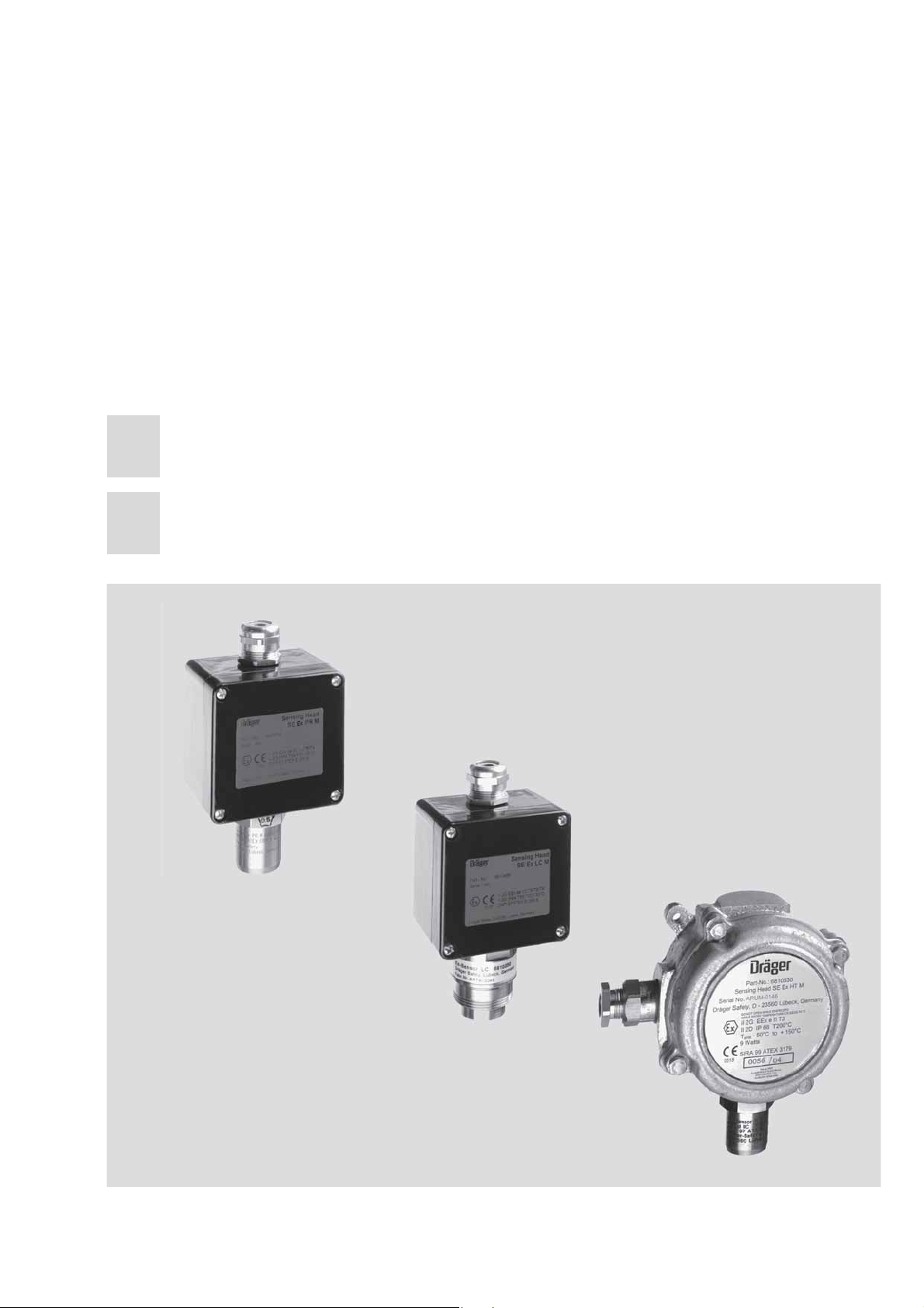
Polytron SE Ex PR M
Polytron SE Ex LC M
Polytron SE Ex HT M
Messköpfe mit den Zentralgeräten Polytron SE Ex und
de
REGARD – Betriebsanleitung
2 - 29
en
Sensing Heads with Central Controllers Polytron SE Ex
and REGARD – Instructions for Use
30 - 57
00123447_06.eps
Page 2

Inhalt
Inhalt
Zu Ihrer Sicherheit
Verwendungszweck
Gerät installieren
Baugruppenträger
Messkopf
. . . . . . . . . . . . . . . . . . . . . . . . . . . . . . . . . . . . . . . . . . . . . . . . . . . . . . . . . . . . . . . . . . .7
Hinweis
. . . . . . . . . . . . . . . . . . . . . . . . . . . . . . . . . . . . . . . . . . . . . . . . . . . . . . . . . . . . . . . . . 8
Lüftungsverhältnisse beachten!
Dichte des Gases beachten!
Elektrische Anschlüsse installieren
. . . . . . . . . . . . . . . . . . . . . . . . . . . . . . . . . . . . . . . . . . . . . . . . . . . . . . . . . 3
. . . . . . . . . . . . . . . . . . . . . . . . . . . . . . . . . . . . . . . . . . . . . . . . . . . . . . . . 4
. . . . . . . . . . . . . . . . . . . . . . . . . . . . . . . . . . . . . . . . . . . . . . . . . . . . . . . . . . . 7
. . . . . . . . . . . . . . . . . . . . . . . . . . . . . . . . . . . . . . . . . . . . . . . . . . . . . . . . . . .7
. . . . . . . . . . . . . . . . . . . . . . . . . . . . . . . . . . . . . . . . . . . 8
. . . . . . . . . . . . . . . . . . . . . . . . . . . . . . . . . . . . . . . . . . . . . . 8
. . . . . . . . . . . . . . . . . . . . . . . . . . . . . . . . . . . . . . . . . . . .9
Verbindung zwischen Messköpfen Polytron SE Ex PR M bzw.
SE Ex LC M und Baugruppenträger
. . . . . . . . . . . . . . . . . . . . . . . . . . . . . . . . . . . . . . . 9
Verbindung zwischen Messkopf Polytron SE Ex HT M
und Baugruppenträger
. . . . . . . . . . . . . . . . . . . . . . . . . . . . . . . . . . . . . . . . . . . . . . . . . . . 9
Sicherheitstechnische Hinweise zur Installation des Messkopfes
Polytron SE Ex HT M
Anschluss an Zentralgerät Polytron SE Ex
Anschluss an Zentralgerät REGARD Ex
Gerät in Betrieb nehmen
Alarme verriegeln
Sensorstrom einstellen
Messkopf Polytron SE Ex kalibrieren / justieren
Nullpunkt einstellen
Empfindlichkeit einstellen
Kalibrieren beenden
. . . . . . . . . . . . . . . . . . . . . . . . . . . . . . . . . . . . . . . . . . . . . . . . . . . . 10
. . . . . . . . . . . . . . . . . . . . . . . . . . . . . . . . 13
. . . . . . . . . . . . . . . . . . . . . . . . . . . . . . . . . . 14
. . . . . . . . . . . . . . . . . . . . . . . . . . . . . . . . . . . . . . . . . . . . . . . . . . 15
. . . . . . . . . . . . . . . . . . . . . . . . . . . . . . . . . . . . . . . . . . . . . . . . . . . . . . . . . . 15
. . . . . . . . . . . . . . . . . . . . . . . . . . . . . . . . . . . . . . . . . . . . . . . . . . . . . 15
. . . . . . . . . . . . . . . . . . . . . . . . . . . . . . 16
. . . . . . . . . . . . . . . . . . . . . . . . . . . . . . . . . . . . . . . . . . . . . . . . . . . . . 16
. . . . . . . . . . . . . . . . . . . . . . . . . . . . . . . . . . . . . . . . . . . . . . . 17
. . . . . . . . . . . . . . . . . . . . . . . . . . . . . . . . . . . . . . . . . . . . . . . . . . . . 18
Instandhaltung
Wartungsintervalle
Wartung
Sensor auswechseln
. . . . . . . . . . . . . . . . . . . . . . . . . . . . . . . . . . . . . . . . . . . . . . . . . . . . . . . . . . . . 19
. . . . . . . . . . . . . . . . . . . . . . . . . . . . . . . . . . . . . . . . . . . . . . . . . . . . . . . . . 19
. . . . . . . . . . . . . . . . . . . . . . . . . . . . . . . . . . . . . . . . . . . . . . . . . . . . . . . . . . . . . . . . . . 20
. . . . . . . . . . . . . . . . . . . . . . . . . . . . . . . . . . . . . . . . . . . . . . . . . . . . 20
Messfunktion für den Explosionsschutz
Technische Daten
Abmessungen
Maß-Skizze (in mm)
Bestell-Liste
Messköpfe
Zubehör
Ersatzteile
. . . . . . . . . . . . . . . . . . . . . . . . . . . . . . . . . . . . . . . . . . . . . . . . . . . . . . . . . . . . . . . . 27
. . . . . . . . . . . . . . . . . . . . . . . . . . . . . . . . . . . . . . . . . . . . . . . . . . . . . . . . . . . . . . . . . . . 27
. . . . . . . . . . . . . . . . . . . . . . . . . . . . . . . . . . . . . . . . . . . . . . . . . . . . . . . . . . . . . . . . . 27
EG-Konformitätserklärungen
Stichwortverzeichnis
. . . . . . . . . . . . . . . . . . . . . . . . . . . . . . . . . . . . . . . . . . . . . . . . . . . . . . . . . 24
. . . . . . . . . . . . . . . . . . . . . . . . . . . . . . . . . . . . . . . . . . . . . . . . . . . . . . . . . . . . . 26
. . . . . . . . . . . . . . . . . . . . . . . . . . . . . . . . . . . . . . . . . . . . . . . . . . . . . . . . 26
. . . . . . . . . . . . . . . . . . . . . . . . . . . . . . . . . . . . . . . . . . . . . . . . . . . . . . . . . . . . . . . 27
. . . . . . . . . . . . . . . . . . . . . . . . . . . . . . . . . . . . . . . . . . . . . . 27
. . . . . . . . . . . . . . . . . . . . . . . . . . . . . . . . . . . . . . . . . . . . . . . . . . . . . . 28
2
. . . . . . . . . . . . . . . . . . . . . . . . . . . . . . . . . . . . 22
Page 3

3
Zu Ihrer Sicherheit
Betriebsanleitung beachten
Jede Handhabung an dem Messkopf setzt die genaue Kenntnis und Beachtung dieser Betriebsanleitung voraus.
Der Messkopf ist nur für die beschriebene Verwendung bestimmt.
Instandhaltung
Instandsetzung des Messkopfes nur durch Fachleute.
Für den Abschluss eines Service-Vertrages sowie für Instandsetzungen empfehlen
wir Dräger Service.
Bei Instandhaltung nur Original-Dräger-Teile verwenden.
Kapitel “Wartungsintervalle” auf Seite 19 beachten.
Zu Ihrer Sicherheit
Einsatz in explosionsgefährdeten Bereichen
Geräte oder Bauteile, die in explosionsgefährdeten Bereichen genutzt werden und
nach Internationalen oder Europäischen Explosionsschutz-Richtlinien geprüft und
zugelassen sind, dürfen nur unter den angegebenen Bedingungen eingesetzt
werden.
Änderungen dürfen an den Betriebsmitteln nicht vorgenommen werden. Der Einsatz
von defekten oder unvollständigen Teilen ist unzulässig.
Bei Instandsetzung an diesen Geräten oder Bauteilen müssen die relevanten
gesetzlichen Bestimmungen beachtet werden.
Haftung für Funktion bzw. Schäden
Die Haftung für die Funktion des Messkopfes geht in jedem Fall auf den Eigentümer
oder Betreiber über, soweit der Messkopf von Personen, die nicht Dräger Safety
angehören, unsachgemäß gewartet oder instand gesetzt wird oder wenn eine Handhabung erfolgt, die nicht der bestimmungsgemäßen Verwendung entspricht.
Für Schäden, die durch die Nichtbeachtung der vorstehenden Hinweise eintreten,
haftet Dräger Safety nicht.
Gewährleistungs- und Haftungsbedingungen der Verkaufs- und Lieferbedingungen
von Dräger Safety werden durch vorstehende Hinweise nicht erweitert.
Dräger Safety AG &Co. KGaA
Page 4

Verwendungszweck
Verwendungszweck
Die Messköpfe Polytron SE Ex PR M, SE Ex HT M und SE Ex LC M sind vorgesehen
zur stationären kontinuierlichen Überwachung von brennbaren Gas-Luft bzw. DampfLuft-Gemischen unterhalb der Unteren ExplosionsGrenze (UEG) bzw. unterhalb von
10 % der UEG unter atmosphärischen Bedingungen.
Die Messköpfe sind gekennzeichnet durch die Gerätekategorie II 2G und II 2D und
somit für den Einsatz in explosionsgefährdeten Bereichen der Zonen 1 und 2 sowie
der Zonen 21 und 22 zugelassen.
Die Messköpfe Polytron SE Ex PR M und SE Ex LC M sind für den Gasexplosionsschutz gemäß Gerätekategorie 2 (Einsatz in den Zonen 1 oder 2) in der Zündschutzart Druckfeste Kapselung "d" und Erhöhte Sicherheit "e" ausgeführt.
Für den Staubexplosionsschutz gemäß Gerätekategorie 2 (Einsatz in den Zonen 21
oder 22) sind sie in der Gehäuseschutzart IP 6x ausgeführt.
C
Der Messkopf Polytron SE Ex HT M ist im Sinne der Richtlinie 94/9/EG eine Baugruppe und setzt sich aus drei Teilen (Ex-Sensor HT M, Gehäuse und Kabelverschraubung) zusammen, die individuell gemäß Richtlinie 94/9/EG
bauartzugelassen und durch die Gerätekategorie II 2GD gekennzeichnet sind. Der
Messkopf ist somit geeignet zum Einsatz in explosionsgefährdeten Bereichen der
Zonen 1 und 2 sowie der Zonen 21 und 22.
Messkopf Polytron SE Ex PR M für den Messbereich 0 bis 100 %UEG
Der Messkopf Polytron PR M beinhaltet den Anbau eines Gassensors Typ ExSensor PR M (Zündschutzart Druckfeste Kapselung und Erhöhte Sicherheit "de",
bzw. Gehäuseschutzart IP 6x, DMT 97 ATEX E 001 X). Der Messkopf Polytron
SE Ex PR M darf nicht bei Umgebungstemperaturen von weniger als –50
ben werden. Die maximal zulässige Umgebungstemperatur liegt für die Temperaturklasse T6 bei 40
Staubexplosionsschutz: Bei den maximal zulässigen Umgebungstemperaturen von
o
40
C bzw. 55
bzw. 100
o
C, für T5 bei 55
o
C bzw. 85
o
C bzw. 135
o
C und für T4 bei 85
o
C beträgt die maximale Oberflächentemperatur 85
o
C.
o
C.
o
C betrie-
o
C
Zur Messfunktion für den Explosionsschutz siehe Seite 22.
Messkopf Polytron SE Ex HT M für Messbereich 0 bis 100 %UEG und Einsatztemperatur bis 150
o
Der Messkopf Polytron SE Ex HT M beinhaltet den Anbau eines Gassensors Typ ExSensor HT M (Zündschutzart Druckfeste Kapselung und Erhöhte Sicherheit "de",
bzw. Gehäuseschutzart IP 6x, DMT 97 ATEX E 001 X). Er darf nicht bei Umgebungstemperaturen von weniger als –50
Umgebungstemperatur liegt für die Temperaturklasse T3 bei 150
Staubexplosionsschutz: Bei der maximal zulässigen Umgebungstemperatur von
o
150
C beträgt die maximale Oberflächentemperatur 200
o
C betrieben werden. Die maximal zulässige
o
C.
o
C.
Zur Messfunktion für den Explosionsschutz siehe Seite 22.
4
Page 5

5
Messkopf Polytron SE Ex LC M für den Messbereich 0 bis 10 %UEG
Der Messkopf Polytron SE Ex LC M beinhaltet den Anbau eines Gassensors Typ ExSensor LC M (Zündschutzart Druckfeste Kapselung und Erhöhte Sicherheit "de",
bzw. Gehäuseschutzart IP 6x, DMT 02 ATEX E 188 X). Der Messkopf Polytron SE Ex
LC M darf nicht bei Umgebungstemperaturen von weniger als –40
werden. Die maximal zulässige Umgebungstemperatur liegt für die Temperaturklasse T6 bei 40
Staubexplosionsschutz: Bei den maximal zulässigen Umgebungstemperaturen von
o
40
C bzw. 50
bzw. 100
o
C, für T5 bei 50
o
C bzw. 85
o
C bzw. 135
o
C und für T4 bei 85
o
C beträgt die maximale Oberflächentemperatur 85
o
o
C.
o
C betrieben
o
C
Nicht für den Einsatz bei erhöhtem Sauerstoffgehalt.
C.
Verwendungszweck
In Verbindung mit den Zentralgeräten Polytron SE Ex oder REGARD Ex mit voreingestellten Alarmschwellen können akustische oder optische Alarmmittel aktiviert
oder automatisch Gegenmaßnahmen eingeleitet werden, noch bevor die detektierten Gase oder Dämpfe im Gemisch mit Luft gefährliche zündfähige Konzentrationen annehmen.
Folgende Hinweise sind in Bezug auf die Messfunktion zu beachten:
1. Verhalten bei sehr hohen Gaskonzentrationen:
Grundsätzlich ist das Messprinzip Wärmetönung, das auf der katalytischen
Oxidation eines brennbaren Gases beruht, nicht eindeutig, da bei hohen Messgaskonzentrationen die im Sensor enthaltene Sauerstoffkonzentration zur Oxidation des brennbaren Gases nicht mehr ausreicht. Daher verringert sich das
Messsignal bei sehr hohen Gaskonzentrationen und kann Werte innerhalb des
Messbereichs annehmen. Das nachgeschaltete Steuergerät muss mit Anzeigeeinrichtungen und Messwertausgängen (sofern vorhanden) sowie Alarmausgängen betrieben werden, die bei Messbereichsüberschreitung selbsthaltend
sind.
Solche selbsthaltenden Alarme dürfen erst dann zurückgesetzt werden, wenn
durch eine von der Gaswarnanlage unabhängige Messung nachgewiesen ist,
dass die Konzentration brennbarer Gase oder Dämpfe unterhalb des Messbereichsendwertes liegt.
2. Mindest-Sauerstoffgehalt:
Das Messprinzip Wärmetönung erfordert einen Mindest-Sauerstoffgehalt von
12 %V/V, andernfalls werden aufgrund von Sauerstoffmangel zu geringe Messwerte angezeigt.
Page 6

Verwendungszweck
3. Langzeitige Begasung mit Methan bei sehr tiefen Temperaturen
Werden die Messköpfe Polytron SE Ex PR M oder SE Ex HT M bei sehr tiefen
Temperaturen betrieben und mit Methan/Luftgemischen begast, so kann sich das
Messsignal bei langzeitiger Begasung nach Alarmgabe verringern und zu Fehlinterpretation Anlass geben.
Eine eingehende Untersuchung dieses Effekts zeigte, dass sich das Messsignal
bei –50
20 %UEG verringern kann
o
C und 90-minütiger Begasung mit 40 %UEG Methan auf bis zu
1)
.
Tritt ein Gasalarm auf, so müssen unverzüglich Gegenmaßnahmen eingeleitet
werden. Ein nach Alarmgabe möglicherweise auftretender langsamer Abfall des
Messsignals darf nicht zu der Annahme führen, dass sich die Gaskonzentration
verringert habe.
Wir empfehlen, die Alarmmeldungen der nachgeschalteten Zentralgeräte selbsthaltend auszuführen und erst dann zurückzusetzen, wenn durch eine von der Gaswarnanlage unabhängige Messung ein gefahrloser Zustand nachgewiesen ist.
Wichtiger Hinweis
Obwohl der Messkopf vor der Auslieferung auf seine Funktion geprüft wurde, muss
nach dessen Installation eine Inbetriebnahme einschließlich der Kalibrierung von
Nullpunkt und Empfindlichkeit durchgeführt werden.
Die Inbetriebnahme muss mit einer Funktionsprüfung der kompletten Gaswarnanlage abgeschlossen werden.
1)
Bei Temperaturen oberhalb von –50
signal bei –10
ab. Für andere Gase ist die Abnahme des Messsignals bei Langzeitbegasung und tiefen
Temperaturen deutlich geringer.
o
C und 90-minütiger Begasung mit 40 %UEG Methan um maximal 8 %UEG
o
C fällt dieser Effekt geringer aus, z.B. fällt das Mess-
6
Page 7

Gerät installieren
Baugruppenträger
— Installation in einem nicht explosionsgefährdeten Bereich.
Zentralgerät Polytron SE Ex:
— Einbau in Schalttafel für Baugruppenträger mit zwei und fünf Kanaleinschüben.
Zentralgeräte Polytron SE Ex und REGARD Ex:
— Einbau in 19"-Schaltschrank für Baugruppenträger mit maximal 12 (Polytron) bzw.
16 (REGARD) Kanaleinschüben.
7
Gerät installieren
Belüftung berücksichtigen.
— Mindestabstand zum Gehäusedeckel 50 mm.
Bei mehr als zwei Baugruppenträgern übereinander muss eine Zwangsbelüftung
vorgesehen werden.
— Nationale Bestimmungen Berührungsschutz beachten (in Deutschland: VDE-Be-
stimmungen).
Alle Informationen zum Zentralgerät Polytron SE Ex - bestehend aus Baugruppenträger, Kanaleinschüben und Quittiereinschub - bezüglich Installation, Inbetriebnahme, Betrieb, Funktion und Wartung entnehmen Sie bitte der Betriebsanleitung
Polytron SE Ex Zentralgerät, Bestell-Nr. 90 23 207, die mit dem Baugruppenträger
Polytron SE Ex ausgeliefert wird.
Bezüglich Informationen zum Zentralgerät REGARD – bestehend aus Baugruppenträger und Kanaleinschüben – sei in gleichem Zusammenhang auf die Betriebsanleitung REGARD, Bestell-Nr. 42 05 746 verwiesen.
Messkopf
Verordnungen über elektrische Betriebsmittel in explosionsgefährdeten Bereichen
und Zulassungsbedingungen beachten.
Gebrauchslage:
Das Messsignal des Messkopfes ist lageabhängig. Der Messkopf muss daher so
montiert werden dass die Gaseintrittsfläche des Sensors nach unten weist. Bei
Deckenmontage sollten Montagewinkel verwendet werden.
— Montage des Messkopfes in vertikaler Lage an einem vibrationsarmen, möglichst
temperaturstabilen Ort (direkte Sonneneinstrahlung vermeiden) in der Nähe einer
möglichen Leckagestelle.
Page 8

Gerät installieren
— Der volle Umfang von Umwelteinflüssen, denen der Messkopf ausgesetzt sein
kann, ist zu beachten. Äußere Einflüsse wie Schwallwasser, Öl, korrosive Aerosole (Salznebel) usw. sowie die Möglichkeiten mechanischer Beschädigungen
sind zu vermeiden.
— Freiraum von mindestens 30 cm unterhalb des Messkopfes für die Zugänglichkeit
bei Kalibrierarbeiten einhalten.
Befestigung der Messköpfe Polytron SE Ex PR M und SE Ex LC M mit Schrauben
(Durchmesser 4 mm) durch das Gehäuse, für den Messkopf Polytron SE Ex HT M
werden Schrauben mit einem Durchmesser von 6 mm benötigt (siehe Maß-Skizze
auf Seite 59).
Hinweis
Bestimmte Stoffe in der zu überwachenden Atmosphäre können die Messempfindlichkeit der im Messkopf eingebauten Sensoren (Ex-Sensor PR M, Ex-Sensor HT M
und Ex-Sensor LC M) beeinträchtigen:
a) Polymerisierende Stoffe wie z.B. Acrylnitril, Butadien und Styrol,
b) korrosive Stoffe wie z.B. Ammoniak und Halogenkohlenwasserstoffe (bei deren
katalytischer Oxidation Halogene wie Brom, Chlor oder Fluor freigesetzt werden)
wie auch Halogenwasserstoffsäuren,
c) Katalysatorgifte wie Schwefel- und Phosphorverbindungen, Siliziumverbin-
dungen (insbesondere Silicone) und metall-organische Dämpfe.
Die eingesetzten Sensoren enthalten Messelemente (Pellistoren) vom Typ "poisonresistant" (PR), die beim Auftreten von Katalysatorgiften eine längere Lebensdauer
haben als herkömmliche Sensoren. Dennoch gilt die Regel, dass die Kalibrierintervalle bzw. Überprüfungsintervalle entsprechend kürzer gewählt werden müssen,
wenn mit der Anwesenheit von Katalysatorgiften in der zu überwachenden Atmosphäre zu rechnen ist.
Lüftungsverhältnisse beachten!
— Messkopf mit Sensor immer im Luftstrom zwischen möglicher Austritts- bzw.
Sammelstelle und möglicher Zündquelle anordnen.
Dichte des Gases beachten!
— Bei Gasen, deren Dichte geringer als die der Luft ist, wie Wasserstoff, Methan
oder Ammoniak, muss der Messkopf über einer möglichen Leckagestelle bzw. an
den höchsten Punkten, an denen sich diese Gase in größeren Konzentrationen
befinden können, angeordnet werden.
— Bei Gasen und Dämpfen mit einer Dichte, die größer als die der Luft ist, muss der
Messkopf unter einer möglichen Leckagestelle bzw. an den tiefsten Punkten, an
denen diese Gase und Dämpfe vorhanden sein können, montiert werden.
8
Page 9
Elektrische Anschlüsse installieren
— Verlegung und Anschluss der elektrischen Installation nur vom Fachmann unter
Beachtung der einschlägigen Vorschriften.
— Sämtliche Anschlüsse erfolgen an Klemmen an der Rückseite des Baugruppen-
trägers.
— Verbindung vom Baugruppenträger zu einer zentralen Klemmenleiste mit flexi-
blen Leitungen.
●
Leitungen mit den mitgelieferten Kabelbindern am Baugruppenträger gegen Zugbelastung schützen.
●
Bei der Leitungsführung nationale Bestimmungen zu Trennung von Netz-, Kleinspannungs- und Steuerstromkreis beachten.
●
Abschirmung an Masse Schaltschrank oder Schalttafel anschließen.
9
≥
Gerät installieren
≥
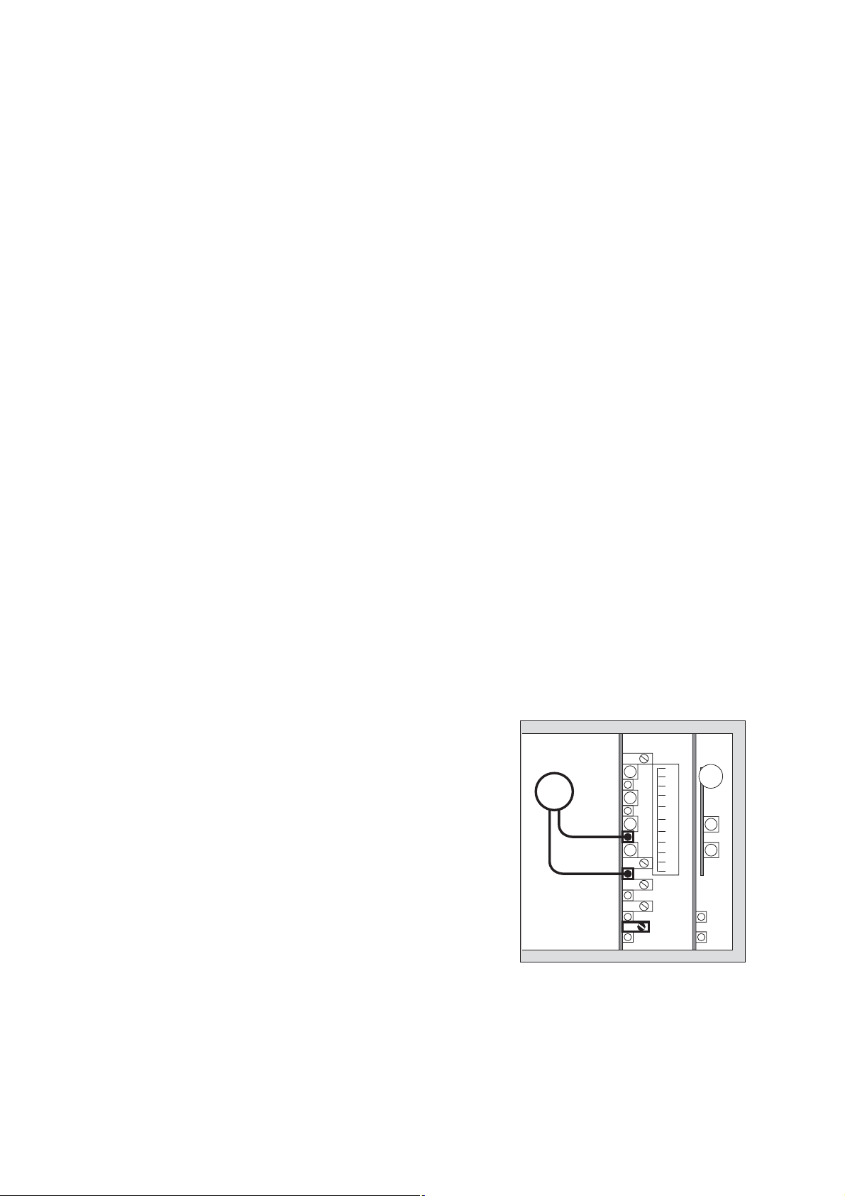
Verbindung zwischen Messköpfen Polytron SE Ex PR M bzw. SE Ex LC M und
Baugruppenträger
●
Mit 3-adriger, abgeschirmter Leitung, Abschirmgeflecht mit Bedeckungsgrad
80 %. Außendurchmesser maximal 12 mm.
●
Abschirmung an Masse Schaltschrank oder Schalttafel möglichst kurz anschließen.
●
Kabelschirm wie in der Darstellung gezeigt um den Kunststoff-Konus legen und
in die Metall-Kabelverschraubung einsetzen. Durch Festziehen der Kabelverschraubung hat der Kabelschirm elektrischen Kontakt zur leitfähigen Innenbeschichtung des Messkopfes. Durch diese Maßnahme ist die geforderte
Störfestigkeit nach 89/336/EWG sichergestellt.
Hinweise zur Kabelverschraubung
Die Kabelverschraubung ist ausschließlich für die ortsfeste Installation zugelassen.
Sie ist geeignet für Leitungsdurchmesser von 7 bis 12 mm.
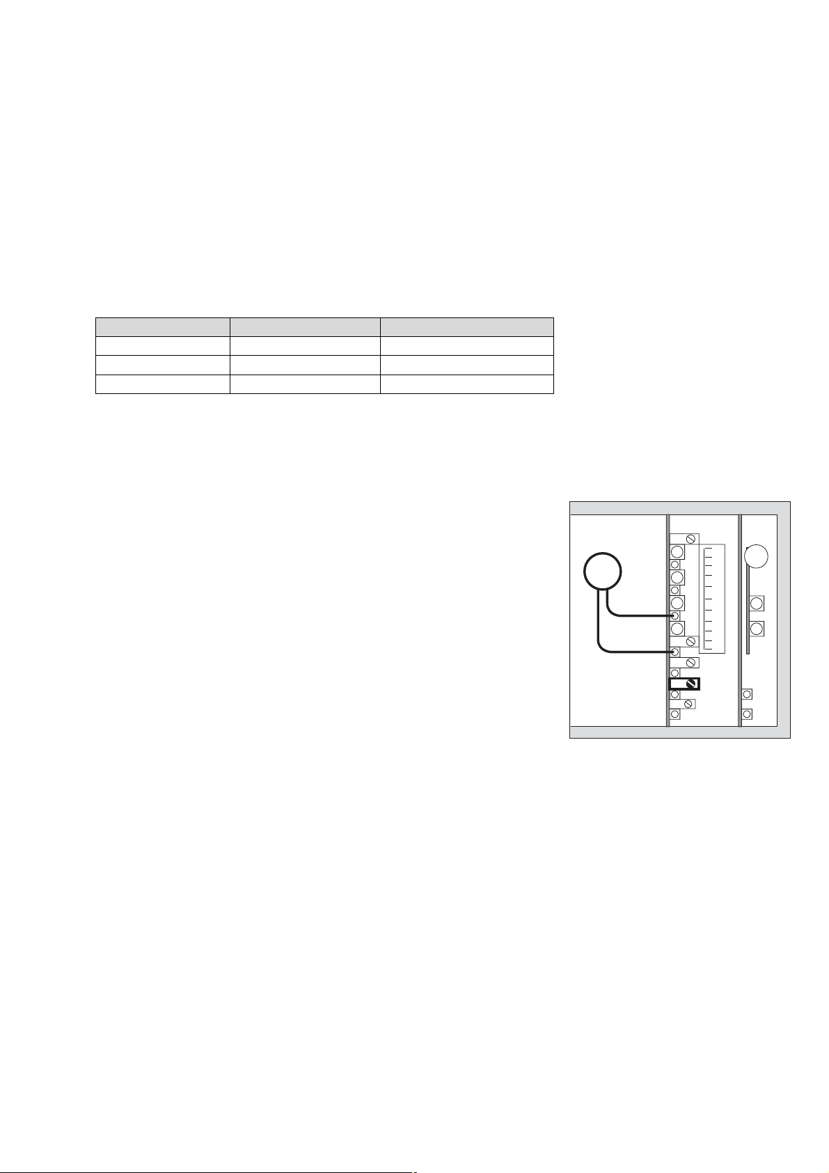
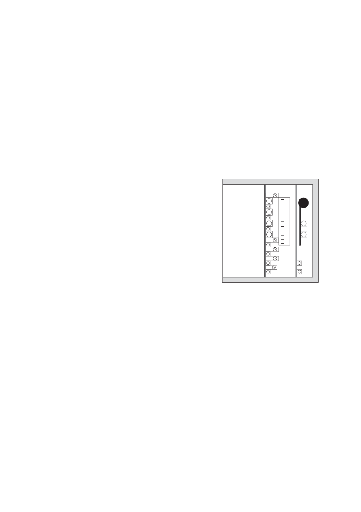
Verbindung zwischen Messkopf Polytron SE Ex HT M und Baugruppenträger
●
Mit 3-adriger, abgeschirmter Leitung, Abschirmgeflecht mit Bedeckungsgrad
80%. Außendurchmesser maximal 12 mm.
●
Abschirmung nur dann an Masse Schaltschrank oder Schalttafel anschließen,
wenn diese nicht im/am Messkopf auf Erdpotential bzw. Potentialausgleich liegt.
∼45 mm
ab
∼12 mm
cd
00223447_06.eps
Page 10

Gerät installieren
Sicherheitstechnische Hinweise zur Installation des Messkopfes
Polytron SE Ex HT M
Sicherheitsrelevante Hinweise zur Kabelverschraubung (Serie A2LF)
Technische Daten:
Typ: A3LF / 20S
("3" verweist auf Silikon-Dichtring)
Gewinde: M 20 x 1,5 (metrisch)
Material: Messing
Klemmbereich: 7,2 bis 11,7 mm
Schutzart: IP 68
Hersteller: Peppers Cable Glands Ltd.,
Stanhope Road,
Camberley, GU15 3BT, U.K.
Zulassung: II 2 GD EEx e II
SIRA 01 ATEX 1272X
o
Betriebstemperaturbereich: –60
C bis +180 oC
Die in der Kabelverschraubung eingeprägte Typenbezeichnung A3LF enthält die "3"
als Hinweis auf eine Silikondichtung. Nur der Typ A3LF ist mit dieser Silikondichtung
(weiße Farbe) ausgestattet und darf deshalb in dem Temperaturbereich –60
o
C betrieben werden.
+180
o
C bis
Die Kabelverschraubung ist nur für ortsfeste Installation geeignet, es ist eine effektive Zugentlastung bzw. Verdrehsicherung des Kabels vorzusehen.
Folgende Angaben des Herstellers zur Kabelverschraubung A3LF sind zu berücksichtigen:
Kurzbeschreibung:
Die Peppers-Kabelverschraubung ist vorgesehen für die Außenanwendung in explosionsgefährdeten Bereichen für nicht-armiertes abgeschirmtes Kabel, wobei die
Schirmung nicht von der Verschraubung gefasst wird und deshalb ggf. separat im
Gehäuse aufzulegen ist. Sie ist hinsichtlich Temperatur, Feuchte und Vibration für
normale industrielle Umgebung geeignet. Vor der Installation muss die Materialverträglichkeit hinsichtlich Chemikalien oder aggressiven Substanzen geprüft werden.
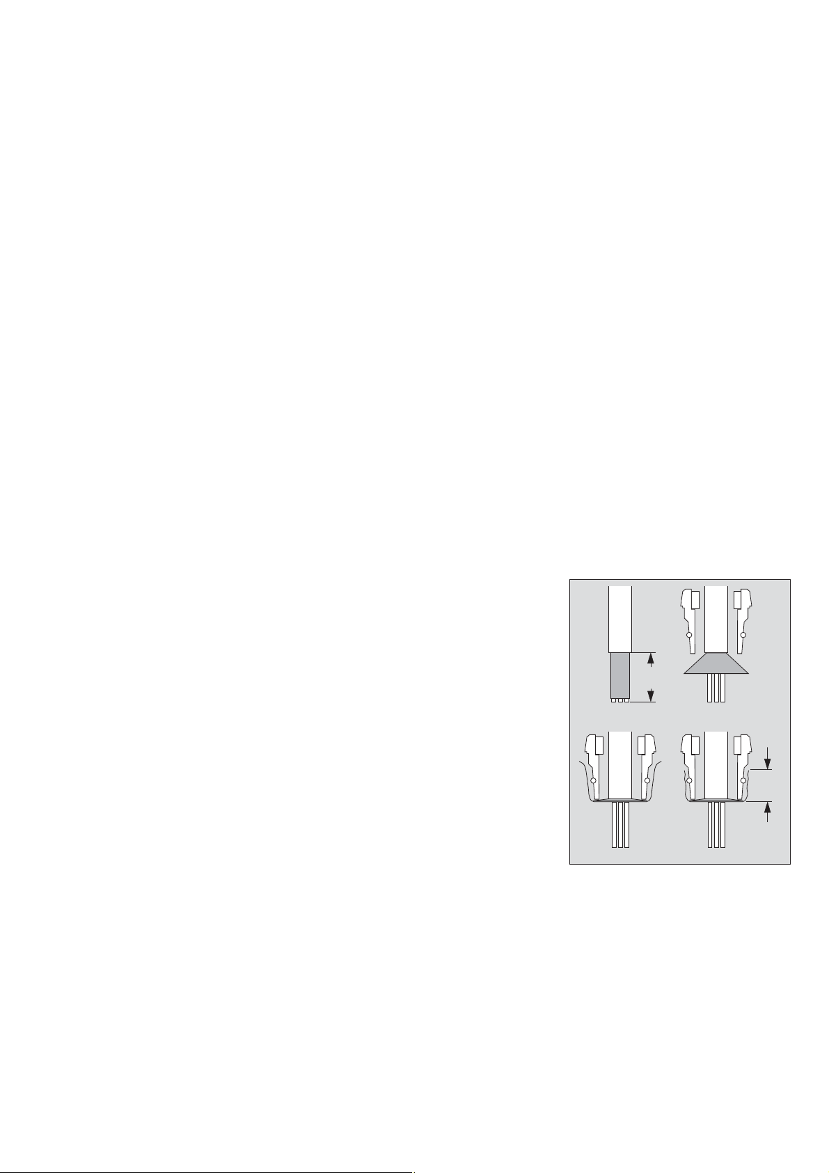
Weiterhin ist auf einwandfreien Sitz des O-Rings (1) zu achten.
Kabel vorbereiten wie erforderlich
Montage der Mantelleitung:
Die 3-adrige abgeschirmte Mantelleitung wird entsprechend den Anforderungen
abgesetzt bzw. abisoliert und soweit in die Kabelverschraubung eingesetzt, dass der
Kabelmantel in der Kabelverschraubung verbleibt (siehe Abbildung). Der Pressring
muss den Kabelmantel zuverlässig umschließen. Danach unter Zuhilfenahme von
zwei Schraubenschlüsseln (3: M24, 2: M25) die Verschraubung 3 in die Verschrau-
bung 2 hineindrehen. Das korrekte Drehmoment hierfür beträgt 25 Nm.
10
32
14
00323447_06_de.eps
Page 11

Achtung:
Doppelerdungen können zu EMV-Problemen führen. Um solche Störungen zu vermeiden ist es erforderlich, die Abschirmung auf nur einer Seite, in der Zentrale oder
am Messkopf, auf Erdpotential zu legen. Da das metallische Messkopfgehäuse mit
seiner äußeren Erdklemme ohnehin auf Erdpotential- bzw. Potentialausgleich gelegt
werden muss, ist es in den meisten Fällen empfehlenswert, die Abschirmung auf die
innere PE-Klemme des Gehäuses aufzulegen und die Abschirmung in der Zentrale
nicht aufzulegen.
Sicherheitsrelevante Hinweise zum Messkopfgehäuse (Typ Range 2000)
Technische Daten:
Typ: Range 2000 (mit Silikon-Dichtring)
Einschraubgewinde: M 20 x 1,5, M 25 x 1,5 (unten)
Material: Grauguss, galvanisiert
Anschlussklemmen: 4 Stück SAKK 4 Ceramic (nummeriert)
Gerät installieren
Schutzart: IP 66
Hersteller: FEEL, Flameproof Electrical Enclosures
Ltd., Tat Bank Road,
Oldbury, B69 4NP, U.K.
Zulassung: II 2 GD EEx e II T3
SIRA 99 ATEX 3179
o
Betriebstemperaturbereich: –60
C bis +150 oC
Folgende Angaben des Herstellers zum Klemmenkasten (EEx e II T3) mit SilikonDichtring sind zu berücksichtigen:
1. Das Gehäuse wurde als Elektrogehäuse konzipiert, das sich für den Einbau in
explosionsfähigen Atmosphären eignet, wie in DIN EN 50014 beschrieben. Der
Einbau muss nach DIN EN 60079 erfolgen sowie den geltenden Verdrahtungsvorschriften des Landes, in dem das Gehäuse installiert wird.
2. Installation
Das Gehäuse ist mit den beiden äußeren Laschen zu montieren. Das Gehäuse
darf unter keinen Umständen durch eine Kabeleinführung gestützt werden. Die
Silikon-Dichtung ist zwischen dem Gehäuse und der Abdeckung anzubringen. Es
ist wichtig, dass die Abdeckung sicher am Rumpf des Gehäuses angebracht wird.
Alle Schrauben zum Befestigen der Abdeckung sind mit einem Drehmoment von
3,5 Nm anzuziehen.
3. Kabeleinführungen
Diese sind entsprechend den Angaben auf dem Zulassungsetikett auf der Abdeckung des Gehäuses auszuwählen.
4. "T"-Werte
Das Gehäuse kann für den Einbau unter verschiedenen Umgebungstemperaturen zugelassen sein. Die Kennzeichnung auf dem Zulassungsetikett der
Gehäuseabdeckung ist hinsichtlich der Umgebungstemperaturen, unter denen
das Gehäuse installiert wird, unbedingt einzuhalten.
11
Page 12

Gerät installieren
5. Leitereinbau
Die Klemmen aller Leiter sind fest anzuziehen. Die Schrauben zum Anziehen der
Klemmen können unter der Klemmenoberfläche liegen. Es ist wichtig, dass ein
Schraubendreher der richtigen Größe eingesetzt wird. Ein zu großer Schraubendreher beschädigt die Klemmenisolierung.
6. Erdung
Das Gehäuse ist mit einem sechskantigen internen und externen Erdungsanschluss M 6 aus Messing versehen. Zum Sichern des Erdungsleiters ist eine
geeignete Ringlasche zu verwenden.
7. Instandhaltung
Wenn die gelegentliche Prüfung des Gehäuses erforderlich ist, wird auf
EN 60079-17 Absatz 4.3 verwiesen, die Anweisungen enthält.
Besondere Aufmerksamkeit ist auf das Anziehen der Klemmenschrauben, Dichtungen und Befestigungsschrauben für die Abdeckung und Erdungsteile zu
richten. Falls diese verloren gehen oder zu ersetzen sind, bestellen Sie bitte ein
entsprechendes Teil bei FEEL. Wenn keine geeigneten Ersatzteile verwendet
werden, kann die Zulassung ungültig werden.
8. Umgebungsbedingungen
Der Anschlusskasten besteht aus Gusseisen und ist mit Befestigungsschrauben
aus nicht rostendem Stahl für die Abdeckung, einer Silikondichtung sowie
Messing-Erdungsschrauben versehen. Die Materialverträglichkeit dieser Teile
gegenüber korrodierenden Stoffen, mit denen das Gehäuse in Kontakt kommen
kann, muss berücksichtig werden.
Das Gehäuse eignet sich für den Einsatz unter normalen Bedingungen in der
Industrie und ist nicht in Bereichen einzubauen, wo sehr hohe Schwingungen auftreten können.
9. Schutz gegen eindringende Stoffe
Das Gehäuse wurde nach IP 66 geprüft. Wenn die Abdeckung fest angezogen
ist und geeignete Kabeleinführungen benutzt werden, kann dieser Schutz unter
normalen Betriebsbedingungen aufrecht erhalten werden. Ein Mindestschutz von
IP 65 ist jedoch unbedingt zu erzielen.
10. Missbrauch
Das Gehäuse ist nur als Elektrogehäuse zu benutzen. Es eignet sich nicht für
andere Funktionen.
11. Werkzeuge
Steckschlüssel von 10 mm für die Befestigungsschrauben der Abdeckung, die
interne und externe Erdung
Der Einbau des Produkts darf nur von erfahrenem Fachpersonal vorgenommen
werden. Flameproof Electrical Enclosures Ltd. (FEEL) übernimmt keine Haftung für
Schäden und Verluste, bedingt durch die Tatsache, dass der Einbau oder Einsatz
der Produkte nicht genau den vorliegenden Anleitungen entspricht.
12
Page 13
Anschluss an Zentralgerät Polytron SE Ex
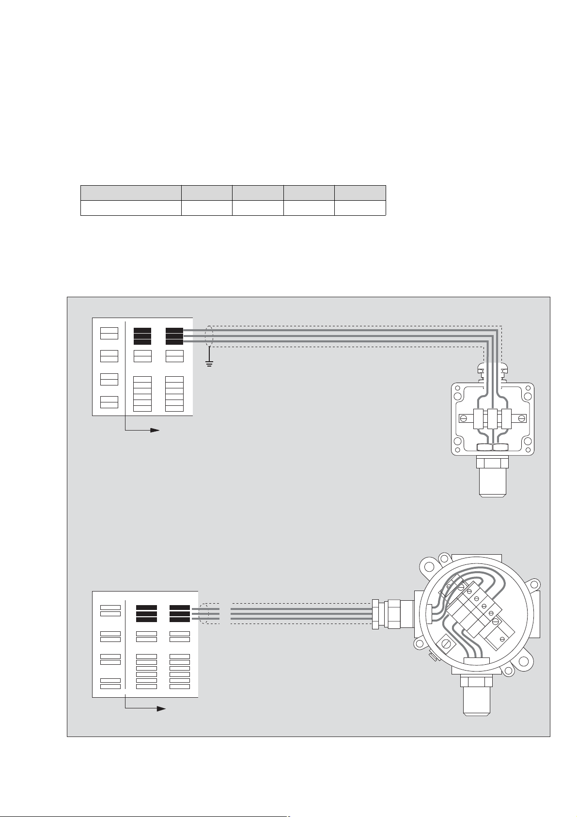
— Der Leitungswiderstand je Ader darf 20 Ω nicht überschreiten.
Daraus ergeben sich für die verschiedenen Aderquerschnitte folgende maximale
Entfernungen:
Aderquerschnitt 1,0 mm
2
1,5 mm
2
2,5 mm
2
4,0mm
2
maximale Leitungslänge 950 m 1 450 m 2 400 m 3 800 m
● Klemmen 1, 2 und 3 des Messkopfes mit den Klemmen 1, 2 und 3 des Baugrup-
penträgers verbinden.
● Alle Verbindungen der Messleitung sorgfältig herstellen.
Die Messleitungen sind entsprechend den Errichtungsvorschriften für den
jeweils vorgesehenen Einsatztemperaturbereich auszuwählen.
3
2
1
+
–
Gerät installieren
3
2
1
+
–
1 ... 12
Polytron SE Ex
3
2
1
Polytron SE Ex
1
PE
2
➀➁
➀➁
3
4
➂
➂
4
1 ... 12
00423447_06.eps
13
Page 14
Gerät installieren
Anschluss an Zentralgerät REGARD Ex
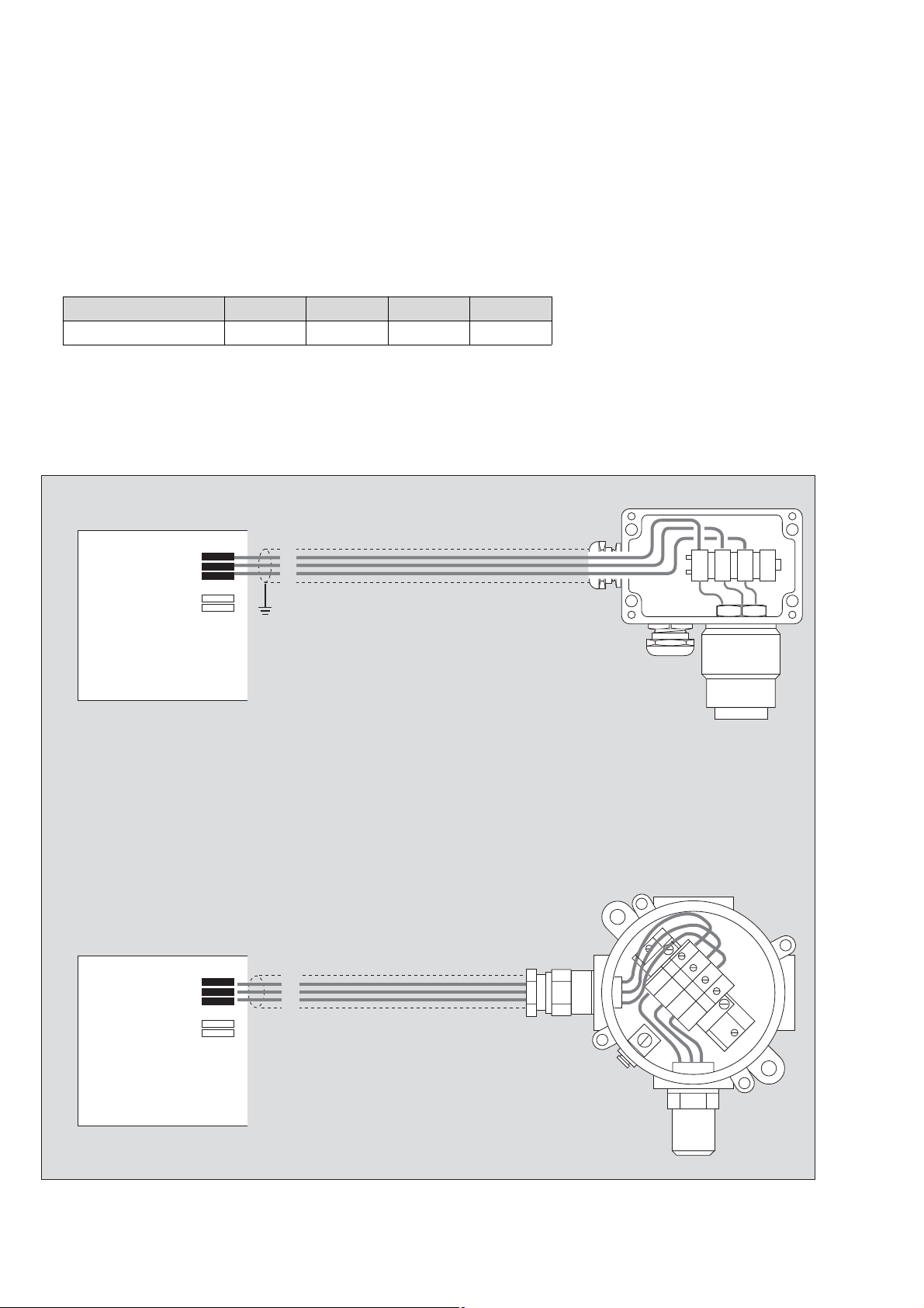
— Der Leitungswiderstand je Ader darf 10 Ω nicht überschreiten.
Daraus ergeben sich für die verschiedenen Aderquerschnitte folgende maximale
Entfernungen:
Aderquerschnitt 1,0 mm
2
1,5 mm
2
2,5 mm
2
4,0mm
2
maximale Leitungslänge 450 m 750 m 1 200 m 1 800 m
● Klemmen 1, 2 und 3 des Messkopfes mit den Klemmen 10, 11 und 12 des Bau-
gruppenträgers verbinden.
● Alle Verbindungen der Messleitung sorgfältig herstellen.
Die Messleitungen sind entsprechend den Errichtungsvorschriften für den jeweils vorgesehenen Einsatztemperaturbereich auszuwählen.
10
11
12
24 V
0 V
10
11
12
24 V
0 V
1
2
3
REGARD Ex
1
2
3
1
PE
2
3
4
➀➁
➂
PE
14
REGARD Ex
00523447_06.eps
Page 15

Gerät in Betrieb nehmen
Alarme verriegeln
Zentralgerät Polytron SE Ex:
Bei Prüfungen und Einstellarbeiten kann es notwendig sein, die Alarmrelais nicht zu
schalten.
1,2 Buchsen am Kanaleinschub mit Drahtbrücke verbinden:
die Relais für den 1. und 2. Alarm bleiben auch bei Alarm angezogen.
3,4Buchsen am Quittiereinschub mit Drahtbrücke verbinden:
das Relais für akustische Warnung bleibt auch bei Alarm abgefallen.
Wichtiger Hinweis:
Bei einer so vorgenommenen Alarmverriegelung wird kein elektrisches Signal
generiert, das auf die Alarmverriegelung hinweist.
Damit das Gaswarnsystem nicht in diesem unsicheren Zustand verbleibt,
müssen organisatorische Maßnahmen getroffen werden.
Zentralgerät REGARD Ex:
— Siehe Gebrauchsanweisung REGARD Ex.
Gerät in Betrieb nehmen
1
3
2
4
00623447_06.eps00723447_06.eps
Sensorstrom einstellen
Zentralgerät Polytron SE Ex:
Für die Methan-Detektion muss der Sensorstrom 270 mA betragen.
Für viele andere Substanzen (siehe Seite 22) sollen die Messköpfe Polytron SE Ex
PR M und SE Ex HT M vorzugsweise mit 240 mA betrieben werden. Nur wenn mit
dem gleichen Sensor auch Substanzen detektiert werden sollen, für die ein Sensorstrom von 240 mA nicht möglich ist, muss der Sensorstrom auf 270 mA eingestellt
werden.
1,2 Voltmeter (R
3 Je nach verwendetem Sensor mit dem Potentiometer den Sensorstrom so ein-
stellen, dass folgende Spannungen auftreten:
Messkopf Polytron ... 240 mA 270 mA 276 mA
SE Ex PR M 528 mV 594 mV – – –
SE Ex HT M 528 mV 594 mV – – –
SE Ex LC M – – – – – – 607 mV
Beispiel:
Der Messkopf Polytron SE Ex HT M soll zu Detektion von n-Hexan auf 240 mA eingestellt werden: Potentiometer 3 so verstellen, dass am Voltmeter 528 mV angezeigt werden.
● Messkopf 10 Minuten in diesem Zustand einlaufen lassen (Anwärmzeit).
≥1 MΩ) an die Buchsen anschließen.
i
mV
=
3
1
2
15
Page 16
Gerät in Betrieb nehmen
Zentralgerät REGARD Ex:
● Mit Hilfe des Menüs »04-8 SETI« den Sensorstrom je nach verwendetem Sensor
auf folgende Werte einstellen:
Messkopf Polytron SE Ex PR M und SE Ex HT M:
– zur Methan-Detektion: 270 mA
– zur Detektion anderer Gase und Dämpfe (siehe Seite 22): 240 mA
Messkopf Polytron SE Ex LC M: 276 mA
● Siehe Betriebsanleitung REGARD Ex.
Messkopf Polytron SE Ex kalibrieren / justieren
Vor der Kalibrierung muss der betreffende Messkopf Polytron SE Ex mindestens
10 Minuten eingelaufen sein. Diese Anwärmzeit ist erforderlich, damit der Sensor
sein thermisches Gleichgewicht erreichen kann.
Nullpunkt einstellen
Ohne Kalibrieradapter:
● Sicherstellen, dass sich der Messkopf in sauberer Umgebungsluft (frei von brenn-
baren Gasen und Dämpfen) befindet,
oder mit Kalibrieradapter:
● Nullgas (saubere Luft oder Stickstoff) mit einem Durchfluss von ca. 0,5 L/min
über den Kalibrieradapter auf den Sensor geben.
Zentralgerät Polytron SE Ex:
1,2 Bei Kanaleinschüben ohne Anzeige oder mit Leuchtbalkenanzeige Voltmeter
(R
≥1 MΩ) an die Buchsen anschließen.
i
Beim Messkopf Polytron SE Ex PR M und SE Ex HT M entsprechen 0 bis 4,7 V
einem Messbereich von 0 bis 100 %UEG, d.h. 1 %UEG entspricht 47 mV.
Beim Messkopf Polytron SE Ex LC M entsprechen 0 bis 4,7 V einem Messbereich von 0 bis 10 %UEG, d.h. 1 %UEG entspricht 470 mV.
3 Mit dem Nullpunktpotentiometer Anzeige auf 0 %UEG (0 mV am Voltmeter) ein-
stellen.
mV
=
1
2
Zentralgerät REGARD Ex:
● Mit Hilfe des Menüs »10-0 ZERO« den Nullpunkt festlegen.
Siehe Betriebsanleitung REGARD Ex.
16
3
00823447_06.eps
Page 17
Empfindlichkeit einstellen
Bei Verwendung von handelsüblichem Prüfgas:
● Je nach verwendetem Messkopf Prüfgas mit der empfohlenen Kalibriergaskon-
zentration (s. Tabelle) mit einem Durchfluss von ca. 0,5 L/min über den Kalibrieradapter leiten.
Empfohlene Konzentrationen:
Messkopf Polytron ... Messbereichsendwert Kalibriergaskonzentration
SE Ex PR M 100 %UEG 40 ... 60 %UEG
SE Ex HT M 100 %UEG 40 ... 60 %UEG
SE Ex LC M 10 %UEG 4 ... 7 %UEG
Das Prüfgas muss aus der zu überwachenden Gaskomponente und Luft bestehen.
In Stickstoff abgefüllte Kalibriergase sind nicht geeignet!
Wenn die Messwertanzeige stabil ist (nach max. 3 Minuten):
Gerät in Betrieb nehmen
Zentralgerät Polytron SE Ex:
4 Mit dem Empfindlichkeitspotentiometer die Anzeige auf den dem Prüfgas ent-
sprechenden Wert einstellen.
Beim Messkopf Polytron SE Ex PR M und SE Ex HT M entsprechen 0 bis 4,7 V
einem Messbereich von 0 bis 100 %UEG, d.h. 1 %UEG entspricht 47 mV.
Beim Messkopf Polytron SE Ex LC M entsprechen 0 bis 4,7 V einem Messbereich von 0 bis 10 %UEG, d.h. 1 %UEG entspricht 470 mV.
Beispiele:
Der Messkopf Polytron SE Ex PR M soll mit 45 %UEG kalibriert werden:
Stelle ein auf 45 x 47 mV = 2115 mV = 2,115 V.
Der Messkopf Polytron SE Ex LC M soll mit 5 %UEG kalibriert werden:
Stelle ein auf 5 x 470 mV = 2350 mV = 2,35 V.
Zentralgerät REGARD Ex:
● Mit Hilfe des Menüs »10-1 SPAN« die Konzentration des Prüfgases eingeben.
Siehe Betriebsanleitung REGARD Ex.
Für die Kalibrierung mit Lösemitteldämpfen kann eine Kalibrierkammer verwendet
werden. In ihr wird eine bestimmte Menge Lösungsmittel verdampft, um z.B.
50 %UEG zu erhalten.
Die Einstellung erfolgt wie bei Prüfgas.
Die Verwendung der Kalibrierkammer setzt beim Bedienungspersonal eine entsprechende Ausbildung und Sachkunde voraus.
Betriebsanleitung der Kalibrierkammer beachten!
mV
=
4
00923447_06.eps
17
Page 18
Gerät in Betrieb nehmen
Wenn sich die der Prüfgaskonzentration entsprechende Spannung - bzw. beim
Zentralgerät REGARD Ex die Prüfgaskonzentration - nicht einstellen lässt:
● Sicherstellen, dass das richtige Prüfgas verwendet wird und dessen Konzentra-
tion mit dem vorgegebenen Zahlenwert in %UEG übereinstimmt.
● Sicherstellen, dass das Prüfgas mit dem erforderlichen Durchsatz von 0,5 L/min
durch den Kalibrieradapter strömt.
Wenn beide Bedingungen erfüllt sind, ist entweder der betreffende Kanaleinschub
defekt oder der Messkopf hat keine ausreichende Empfindlichkeit auf das Gas.
● Sensor wechseln (siehe Seite 20) und/oder Kanaleinschub austauschen.
Nach Entfernen des Prüfgases:
— Kalibrieradapter vom Sensor abnehmen und Prüfgasflasche schließen.
— Messkopf in Atmosphäre, frei von brennbaren Gasen und Dämpfen.
● Anzeige muss auf 0 %UEG (0 mV am Voltmeter) zurückgehen; auf Gasfreiheit
achten.
1 Quittiertaste drücken.
1
Sollte die Anzeige nicht auf 0 zurückgehen:
● Kalibrierung/Justierung wiederholen.
— Lässt sich die Anzeige bei der Kalibrierung nicht mehr auf den dem Prüfgas ent-
sprechenden Wert einstellen, so muss der Ex-Sensor ausgetauscht werden, siehe Seite 20.
Die Einstellarbeiten sind für jeden Kanaleinschub durchzuführen.
Kalibrieren beenden
Zentralgerät Polytron SE Ex:
● Falls die Alarme verriegelt waren: Drahtbrücke für die Alarmunterdrückung entfer-
nen.
● Frontplatte auf den Baugruppenträger montieren.
Zentralgerät REGARD Ex:
● Mit Hilfe des Menüs »00-2 SAVE« die vorgenommene Konfiguration speichern.
Siehe Betriebsanleitung REGARD Ex.
01023447_06.eps
18
Page 19

Instandhaltung
Wartungsintervalle
● Die EN 50073 und die jeweiligen nationalen Regelwerke sind zu beachten.
Täglich
● Sichtkontrolle zur Feststellung der Betriebsbereitschaft.
Bei Inbetriebnahme:
● Sensorstrom einstellen, Seite 15.
● Messkopf kalibrieren / justieren, siehe Seite 16.
In regelmäßigen Abständen,
die von dem Verantwortlichen der Gaswarnanlage festzulegen sind und ein Zeitintervall von 6 Monaten nicht überschreiten sollen:
● Signalübertragung zur Zentrale und Alarmgabe überprüfen - siehe Betriebsan-
leitung der verwendeten Zentraleinheit.
● Messkopf kalibrieren / justieren, siehe Seite 16.
Das Intervall für die regelmäßige Kalibrierung hängt von den Einsatzbedingungen
ab.
Instandhaltung
Insbesondere muss regelmäßig geprüft werden, ob die Sinterscheibe des Sensors
in einem Zustand ist, der den Gaszutritt nicht durch Korrosion oder Ablagerungen
(Staub, Öl, Aerosol) beeinträchtigt.
Halbjährlich
● Inspektion durch Fachleute.
Je nach sicherheitstechnischen Erwägungen, verfahrenstechnischen Gegebenheiten und gerätetechnischen Erfordernissen ist die Länge der Inspektionsintervalle
auf den Einzelfall abzustimmen.
Für den Abschluss eines Service-Vertrages sowie für Instandsetzungen empfehlen
wir den Service von Dräger Safety.
Falls erforderlich
● Sensor auswechseln, Seite 20.
19
Page 20

Instandhaltung
Wartung
Sensor auswechseln
Achtung:
Sensorwechsel bei eingeschaltetem Zentralgerät ist im explosionsgefährdeten
Bereich nicht zulässig.
Auch im sicheren Bereich muss das Zentralgerät zunächst spannungsfrei
geschaltet werden, andernfalls kann der Sensor während des Anschließens
zerstört werden.
● Nationale Vorschriften zum Errichten elektrischer Anlagen in explosionsgefähr-
deten Bereichen beachten (in Europa EN 60 079-14).
● Zentralgerät spannungsfrei schalten oder entsprechenden Kanaleinschub aus
dem Baugruppenträger entnehmen.
Messkopf Polytron SE Ex PR M und SE Ex LC M
● Nach Abschalten der Betriebsspannung Klemmenkasten des Messkopfes öffnen
und Oberteil abnehmen.
1 Sensorkabel lösen
2 Sechskantmutter abschrauben.
3 Alten Sensor ausschrauben und neuen Ex-Sensor einsetzen. Sensorkabel des
neuen Sensors auf 45 mm kürzen und ca. 8 bis 10 mm abisolieren.
2 Neuen Ex-Sensor einschrauben und Sechskantmutter mit Schraubensicherungs-
lack, z.B. Loctite Nr. 221 fixieren.
Zum Erhalt der Schutzart IP 65 und aus Gründen des Explosionsschutzes ist auf
einen einwandfreien Sitz des Sensor-Dichtungsrings zu achten.
1 Leitungen des neuen Ex-Sensors an die Klemmen anschrauben:
Klemme 1 - braunes Kabel
Klemme 2 - gelbes Kabel
Klemme 3 - schwarzes Kabel
● Klemmenkasten schließen, dabei auf Staubfreiheit achten.
1
➀➁
3
PE
➂
2
01123447_06.eps
20
1
➀➁
2
PE
➂
3
01223447_06.eps
Page 21

Messkopf Polytron SE Ex HT M
● Nach Abschalten der Betriebsspannung die vier Schrauben an der Oberseite des
Messkopfes lösen und Oberteil abnehmen.
1 Sensorkabel von den Klemmen 1, 2 und 3 lösen
2 Alten Sensor ausschrauben und neuen Ex-Sensor einschrauben.
Sensorkabel des neuen Sensors auf 85 mm kürzen und ca. 8 bis 10 mm abisolieren.
2 Neuen Ex-Sensor einschrauben und mit Schraubensicherungslack, z.B. Loctite
Nr. 221 gegen Selbstlockern fixieren.
Zum Erhalt der Schutzart IP 65 und aus Gründen des Explosionsschutzes ist auf
einen einwandfreien Sitz des Sensor-Dichtungsrings zu achten.
1 Leitungen des neuen Ex-Sensors an die Klemmen anschrauben:
Klemme 1 - braunes Kabel
Klemme 2 - gelbes Kabel
Klemme 3 - schwarzes Kabel
Klemme 4 (falls vorhanden) ist nicht angeschlossen.
● Oberteil mit zugehörigem Silikon-Dichtring aufsetzen und mit den vier Schrauben
festziehen (Drehmoment 3,5 Nm), dabei auf Staubfreiheit achten.
1
PE
2
3
4
Instandhaltung
01323447_06.eps
Messkopf Polytron SE Ex PR M, SE Ex LC M und SE Ex HT M
● Zentralgerät wieder einschalten bzw. Kanaleinschub wieder in den Baugruppen-
träger einschieben
● Anwärmzeit des neuen Ex-Sensors von mindestens 10 Minuten beachten.
● Nach jedem Sensorwechsel ist eine Kalibrierung durchzuführen, siehe Seite 16.
Hinweis:
Der Sensor des Messkopfes Polytron SE Ex LC M darf aus Explosionsschutzgründen nur durch den Service von Dräger Safety (mit einem Spezialwerkzeug) geöffnet
und geschlossen werden.
21
Page 22

Messfunktion für den Explosionsschutz
Messfunktion für den Explosionsschutz
Nur für den Messkopf Polytron SE Ex PR M und SE Ex HT M
Die Messköpfe Polytron SE Ex PR M und SE Ex HT M erfüllen die grundlegenden Sicherheits- und Gesundheitsanforderungen
der Richtlinie 94/9/EG hinsichtlich der Messfunktion für den Explosionsschutz durch Anwendung der Normen EN 61 779-1
und EN 61 779-4 in Verbindung mit dem Zentralgerät Polytron SE Ex (6. Nachtrag zur EG-Baumusterprüfbescheinigung DMT
97 ATEX E 006 X) und dem Zentralgerät REGARD (4. Nachtrag zur EG-Baumusterprüfbescheinigung DMT 02 ATEX G 002 X),
und zwar für folgende Gase und Dämpfe:
Gas oder Dampf CAS-Nr. Chemisches
Symbol
Aceton 67-64-1 CH3COCH
Ammoniak 7664-41-7 NH
3
UEG
%V/V
3
in
Sensorstrom
in mA
Prüfgaskon-
zentration
Propan
in % V/V
Anzeige
bei Begasung
mit Propan
in %UEG
2,5 240 0,99 57 ... 61 ≤ 44
15,4 240 0,51 19 ... 23 ≤ 22
Ansprechzeit
t
0...90
in Sekunden
Benzin 065/095 --- KW-Gemisch 1,1 240 0,51 40 ... 45 ≤ 47
Benzol 71-43-2 C6H
6
2-Butanon (MEK) 78-93-3 CH3COC2H
n-Butan 106-97-8 C4H
10
n-Butylacetat 123-86-4 CH3COOC4H
Diethylether 60-29-7 C2H5OC2H
Dimethylether 115-10-6 CH3OCH
5
5
3
1,2 240 0,51 40 ... 61 ≤ 39
1,5 240 0,51 47 ... 50 ≤ 44
1,4 240 ≤ 37
1,2 240 0,51 50 ... 55 ≤ 65
10
1,7 240 0,51 37 ... 43 ≤ 44
2,7 240 ≤ 32
Ethanol 64-17-5 C2H5OH 3,1 240 0,99 54 ... 59 ≤ 37
Ethen (Ethylen) 74-85-1 C2H
4
Ethylacetat 141-78-6 CH3COOC2H
n-Hexan 110-54-3 C6H
14
2,4 240 ≤ 29
2,0 240 0,99 70 ... 76 ≤ 40
5
1,0 240 0,99 80 ... 91 ≤ 50
Methanol 67-56-1 CH3OH 6,0 240 0,99 45 ... 49 ≤ 38
n-Nonan 111-84-2 C9H
n-Octan 111-65-9 C8H
n-Pentan 109-66-0 C5H
20
18
12
0,7 240 0,51 57 ... 58 ≤ 82
0,8 240 0,51 51 ... 60 ≤ 67
1,4 240 1,05 67 ... 68 ≤ 32
i-Propanol 67-63-0 (CH3)2CHOH 2,0 240 0,51 37 ... 40 ≤ 38
Propan 74-98-6 C3H
Toluol 108-88-3 C6H5CH
Wasserstoff 1333-74-0 H
Acetylen 74-86-2 C2H
8
3
2
2
1,3-Butadien 106-99-0 CH2=CH-CH=CH
Cyclopropan 75-19-4 C3H
6
1,7 240 ≤ 21 / 33
1,1 240 0,51 41 ... 62 ≤ 47
4,0 240 ≤ 11
2,3 270 0,49 33 ... 42 ≤ 20
1,4 270 0,51 37 ... 51 ≤ 49
2
2,4 270 0,99 44 ... 55 ≤ 27
Ethylenoxid 75-21-8 C2H4O 2,6 270 0,51 36 ... 41 ≤ 38
Methan 74-82-8 CH
4
4,4 270 ≤ 15 / 23
Propylenoxid 75-56-9 C3H6O 1,9 270 0,49 41 ... 44 ≤ 38
Propen (Propylen) 115-07-1 C3H
6
1,8 270 0,51 33 ... 49 ≤ 35
22
Page 23

Messfunktion für den Explosionsschutz
Hinweise zur Tabelle:
Linearität Die maximalen Abweichungen von den Sollwerten bis 70 %UEG (Nonan: bis 60 %UEG) betragen für 1,3-Butadien
11 %UEG, für Ammoniak 7 %UEG, für Propylenoxid 6 %UEG, für Wasserstoff 6 %UEG (jedoch unterhalb von
50 %UEG weniger als 2 %UEG) und für alle anderen aufgelisteten Substanzen 5 %UEG.
Spalte 4: Die Werte der unteren Explosionsgrenzen in %V/V wurden dem Band 1 von Brandes, E. und W. Möller: Sicher-
heitstechnische Kenngrößen, Wirtschaftsverlag NW, 2003 (ISBN 3-89701-745-8) entnommen. Für die Einstellung der Geräte am Einsatzort können andere UEG-Werte verbindlich sein.
Spalte 5: Mit Ausnahme von Methan (Detektion bei 240 mA nicht möglich) und den Substanzen Acetylen, 1,3-Butadien,
Cyclopropan, Ethylenoxid, Propen und Propylenoxid (Detektion bei 240 mA nicht untersucht) sollen die
Messköpfe Polytron SE Ex PR M und SE Ex HT M vorzugsweise mit einem Sensorstrom von 240 mA betrieben
werden, siehe Empfehlung Seite 15.
Spalte 7: Die Begasung mit der in Spalte 6 angegebenen Propankonzentration führt beim auf die (in Spalte 1) angegebene
Substanz kalibrierten Messkopf Polytron SE Ex PR M und SE Ex HT M mit Zentralgerät zu der hier angegebenen
Anzeige.
Beispiel: Nach Kalibrierung auf Benzol zeigt das Zentralgerät bei Begasung mit 0,51 %V/V Propan eine Konzentration von 40 bis 61 %UEG an.
Diese Angaben gelten für neuwertige Sensoren und können aufgrund von Exemplarstreuungen um bis zu ±30 %
variieren.
Bei fehlender Angabe: Für diese Stoffe sind Prüfgase mit ca. 50 %UEG des jeweiligen Stoffes erhältlich. Grundsätzlich wird durch Justage mit spezifischem Prüfgas ein Messfehler aufgrund der Exemplarstreuung der Empfindlichkeit der Sensoren vermieden.
Spalte 8: Für Methan und Propan wurden die ersten der beiden angegebenen t
alle anderen t
-Zeiten mit der Kalibrieradapter-Methode bestimmt.
0...90
-Zeiten mit dem Prüfkammer-Verfahren,
0...90
23
Page 24

Technische Daten
Technische Daten
Messkopf Polytron SE Ex PR M
Betriebsparameter
— Konstantstrom, Sensor 240 / 270 mA
— Spannung an den Messpunkten 528 / 594 mV (Zentralgerät Polytron SE Ex)
Elektrische und thermische Kenngrößen:
— maximale Sensorleistung bei 270 mA 1,0 W
— maximale Spannung 60 V
— minimale Umgebungstemperatur: –50 oC
— maximale Umgebungstemperatur: Temperaturklassenzuordnung:
II 2G: T4: 85 oC, T5: 55 oC, T6: 40 oC
II 2D: T135: 85 oC, T100: 55 oC, T85: 40 oC
IP-Schutzart nach EN 60 529: IP 65
Gerätekennzeichnung nach 94/9/EG: Dräger Safety, D-23560 Lübeck, Germany
Sensing Head SE Ex PR M
II 2G EEx de IIC T4/T5/T6
II 2D IP 6x T85/100/135 oC
DMT 97 ATEX E006 X
CE 0158, Baujahr durch Seriennummer
1)
Messkopf Polytron SE Ex LC M
Betriebsparameter
— Konstantstrom, Sensor 276 mA
— Spannung an den Messpunkten 607 mV (Zentralgerät Polytron SE Ex)
Elektrische und thermische Kenngrößen:
— maximale Sensorleistung bei 276 mA 1,0 W
— maximale Spannung 60 V
— minimale Umgebungstemperatur: –40 oC
— maximale Umgebungstemperatur: Temperaturklassenzuordnung:
II 2G: T4: 85 oC, T5: 50 oC, T6: 40 oC
II 2D: T135: 85 oC, T100: 50 oC, T85: 40 oC
IP-Schutzart nach EN 60 529: IP 65
Gerätekennzeichnung nach 94/9/EG: Dräger Safety, D-23560 Lübeck, Germany
Sensing Head SE Ex LC M
II 2G EEx de IIC T4/T5/T6
II 2D IP 6x T85/100/135 oC
DMT 97 ATEX E006 X
CE 0158, Baujahr durch Seriennummer
1)
__________________________
1) Das Baujahr ergibt sich aus dem 3. Buchstaben der auf dem Typenschild befindlichen Seriennummer:
S = 2002, T = 2003, U = 2004, W = 2005, X = 2006, Y = 2007, Z = 2008, A = 2009, B = 2010, C = 2011, usw.
Beispiel: Seriennummer ARSH-0054, der 3. Buchstabe ist S, also Baujahr 2002.
24
Page 25

Umweltbedingungen (Messkopf Polytron SE Ex PR M und SE Ex LC M):
bei Betrieb: Temperaturen s. oben
700 bis 1300 hPa
im explosionsgefährdeten Bereich: 800 bis 1100 hPa
5 bis 95% rel. Feuchte, nicht-kondensierend
bei Lagerung (gilt auch für Ersatzsensoren): –40 bis + 65 oC
700 bis 1300 hPa
10 bis 90 % rel. Feuchte, nicht-kondensierend
Messkopf Polytron SE Ex HT M
Betriebsparameter
— Konstantstrom, Sensor 240 / 270 mA
— Spannung an den Messpunkten 528 / 594 mV (Zentralgerät Polytron SE Ex)
Technische Daten
Elektrische und thermische Kenngrößen:
— maximale Sensorleistung bei 270 mA 1,0 W
— maximale Spannung 60 V
— minimale Umgebungstemperatur: –50 oC
— maximale Umgebungstemperatur: Temperaturklassenzuordnung:
II 2G: T3: 150 oC
II 2D: T200: 150 oC
IP-Schutzart nach EN 60 529: IP 65
Gerätekennzeichnung nach 94/9/EG:
Messkopf Polytron SE Ex HT M: siehe Dräger Safety-Typenschild auf dem Gehäuse:
Dräger Safety, D-23560 Lübeck, Germany
Sensing Head SE Ex HT M
Baujahr durch Seriennummer
1)
1. Ex-Sensor HT M: Dräger Safety, D-23560 Lübeck, Germany
Ex-Sensor HT M
II 2G EEx d IIC T3
II 2D IP 6X T200 oC
DMT 97 ATEX E001 X
CE 0158, Baujahr durch Seriennummer
1)
2. Gehäuse: siehe Dräger Safety-Typenschild auf dem Gehäuse:
Flameproof Electrical Enclosures Ltd., Oldbury, England
Typ Range 2000
II 2G EEx e II T3
II 2D IP 66 T 200 oC
SIRA 99 ATEX 3179
CE 0518, Baujahr
__________________________
1) Das Baujahr ergibt sich aus dem 3. Buchstaben der auf dem Typenschild befindlichen Seriennummer:
S = 2002, T = 2003, U = 2004, W = 2005, X = 2006, Y = 2007, Z = 2008, A = 2009, B = 2010, C = 2011, usw.
Beispiel: Seriennummer ARSH-0054, der 3. Buchstabe ist S, also Baujahr 2002.
25
Page 26

Technische Daten
3. Kabelverschraubung: Peppers Cable Glands Ltd., Surrey GU15 3BT, UK
Typ A3LF
II 2G EEx e II
II 2D IP 68 T 180 oC
SIRA 01 ATEX 1272X
Umweltbedingungen:
Betrieb: –50 bis + 150 oC
700 bis 1300 hPa,
im explosionsgefährdeten Bereich: 800 bis 1100 hPa
5 bis 95 % rel. Feuchte, nicht kondensierend
Lagerung (gilt auch für Ersatzsensoren): –40 bis + 65 oC
700 bis 1300 hPa
10 bis 90 % rel. Feuchte, nicht kondensierend
Abmessungen
Messkopf Polytron SE Ex PR M inkl. Sensor und Kabelverschraubung 80 x 137 x 56 mm B x H x T
Messkopf Polytron SE Ex LC M inkl. Sensor und Kabelverschraubung 80 x 145 x 56 mm B x H x T
Messkopf Polytron SE Ex PR M GB inkl. Sensor und seitlicher Kabelverschraubung 136 x 116 x 56 mm B x H x T
Messkopf Polytron SE Ex LC M GB inkl. Sensor und seitlicher Kabelverschraubung 136 x 124 x 56 mm B x H x T
Messkopf Polytron SE Ex HT M inkl. Sensor und Kabelverschraubung 150 x 160 x 85 mm B x H x T
Maß-Skizze (in mm)
siehe Seite 59
26
Page 27

Bestell-Liste
Benennung und Beschreibung Bestell-Nr.
Messköpfe
Messkopf Polytron SE Ex PR M
für Messbereich 0 ... 100 %UEG
68 09 758
Bestell-Liste
Messkopf Polytron SE Ex PR M GB
für Messbereich 0 ... 100 %UEG
Messkopf Polytron SE Ex HT M
Einsatztemperatur bis 150 oC,
für Messbereich 0 ... 100 %UEG
Messkopf Polytron SE Ex LC M
für Messbereich 0 ... 10 %UEG
Messkopf Polytron SE Ex LC M GB
für Messbereich 0 ... 10 %UEG
68 11 500
68 10 530
68 10 486
68 11 495
Zubehör
Kalibrieradapter
(einsetzbar bis 70 oC)
68 06 978
Ersatzteile
DrägerSensor Ex PR M 68 09 225
DrägerSensor Ex HT M 68 10 526
DrägerSensor Ex LC M 68 10 350
EG-Konformitätserklärungen
Messkopf Polytron SE Ex PR M und LC M
sowie Messkopf Polytron SE Ex HT M
siehe Seite 58.
27
Page 28

Stichwortverzeichnis
Stichwortverzeichnis
Abmessungen . . . . . . . . . . . . . . . . . . . . . . . . . . . . . . . . . . . . . . . . . . . . . . . . . . . . . . . . 26
Alarme verriegeln . . . . . . . . . . . . . . . . . . . . . . . . . . . . . . . . . . . . . . . . . . . . . . . . . . . . . 15
Anschluss an Zentralgerät . . . . . . . . . . . . . . . . . . . . . . . . . . . . . . . . . . . . . . . . . 13, 14
Baugruppenträger
Belüftung . . . . . . . . . . . . . . . . . . . . . . . . . . . . . . . . . . . . . . . . . . . . . . . . . . . . . . . . . . . . . . 7
Berührungsschutz . . . . . . . . . . . . . . . . . . . . . . . . . . . . . . . . . . . . . . . . . . . . . . . . . . . . . . 7
Bestell-Liste . . . . . . . . . . . . . . . . . . . . . . . . . . . . . . . . . . . . . . . . . . . . . . . . . . . . . . . . . . 27
Bohrbilder
Dichte des Gases
Druckfeste Kapselung
EG-Konformitätserklärungen
Elektrische Anschlüsse installieren . . . . . . . . . . . . . . . . . . . . . . . . . . . . . . . . . . . . . . . . 9
Empfindlichkeit einstellen . . . . . . . . . . . . . . . . . . . . . . . . . . . . . . . . . . . . . . . . . . . . . . 17
Erdung
Ersatzteile . . . . . . . . . . . . . . . . . . . . . . . . . . . . . . . . . . . . . . . . . . . . . . . . . . . . . . . . . . . 27
Explosionsgefährdete Bereiche . . . . . . . . . . . . . . . . . . . . . . . . . . . . . . . . . . . . . . . . . . . 3
Gerät in Betrieb nehmen
Gerät installieren
Gerätekategorie . . . . . . . . . . . . . . . . . . . . . . . . . . . . . . . . . . . . . . . . . . . . . . . . . . . . . . . . 4
Haftung
Installation
Instandhaltung . . . . . . . . . . . . . . . . . . . . . . . . . . . . . . . . . . . . . . . . . . . . . . . 3, 12, 19
Instandsetzung . . . . . . . . . . . . . . . . . . . . . . . . . . . . . . . . . . . . . . . . . . . . . . . . . . . . . . . . . 3
. . . . . . . . . . . . . . . . . . . . . . . . . . . . . . . . . . . . . . . . . . . . . . . . . . . . . . . . . . . 59
. . . . . . . . . . . . . . . . . . . . . . . . . . . . . . . . . . . . . . . . . . . . . . . . . . . . . . . . . . . . . . 12
. . . . . . . . . . . . . . . . . . . . . . . . . . . . . . . . . . . . . . . . . . . . . . . . . . . . . . . . . . . . . . . 3
. . . . . . . . . . . . . . . . . . . . . . . . . . . . . . . . . . . . . . . . . . . . . . . . . . . . . . . . . . . 11
. . . . . . . . . . . . . . . . . . . . . . . . . . . . . . . . . . . . . . . . . . . . . . . . . . . . . . 7
. . . . . . . . . . . . . . . . . . . . . . . . . . . . . . . . . . . . . . . . . . . . . . . . . . . . . . . 8
. . . . . . . . . . . . . . . . . . . . . . . . . . . . . . . . . . . . . . . . . . . . . . . . . . . 4
. . . . . . . . . . . . . . . . . . . . . . . . . . . . . . . . . . . . . . . 27, 58
. . . . . . . . . . . . . . . . . . . . . . . . . . . . . . . . . . . . . . . . . . . . . . . 15
. . . . . . . . . . . . . . . . . . . . . . . . . . . . . . . . . . . . . . . . . . . . . . . . . . . . . . . 7
Kabeleinführungen
Kabelverschraubung
Kalibrieren
Langzeitige Begasung
Leitereinbau . . . . . . . . . . . . . . . . . . . . . . . . . . . . . . . . . . . . . . . . . . . . . . . . . . . . . . . . . 12
Messfunktion für den Explosionsschutz
Methan-Detektion
Nullpunkt einstellen
28
. . . . . . . . . . . . . . . . . . . . . . . . . . . . . . . . . . . . . . . . . . . . . . . . . . . . . . . . . . . 16
. . . . . . . . . . . . . . . . . . . . . . . . . . . . . . . . . . . . . . . . . . . . . . . . . . . . 11
. . . . . . . . . . . . . . . . . . . . . . . . . . . . . . . . . . . . . . . . . . . . . . . . . . . . 9
. . . . . . . . . . . . . . . . . . . . . . . . . . . . . . . . . . . . . . . . . . . . . . . . . . . 6
. . . . . . . . . . . . . . . . . . . . . . . . . . . . . . . 4, 22
. . . . . . . . . . . . . . . . . . . . . . . . . . . . . . . . . . . . . . . . . . . . . . . . . . . . . 15
. . . . . . . . . . . . . . . . . . . . . . . . . . . . . . . . . . . . . . . . . . . . . . . . . . . 16
Page 29

Stichwortverzeichnis
Sensor auswechseln
Sensorstrom einstellen . . . . . . . . . . . . . . . . . . . . . . . . . . . . . . . . . . . . . . . . . . . . . . . . . 15
Sicherheit . . . . . . . . . . . . . . . . . . . . . . . . . . . . . . . . . . . . . . . . . . . . . . . . . . . . . . . . . . . . . 3
Staubexplosionsschutz . . . . . . . . . . . . . . . . . . . . . . . . . . . . . . . . . . . . . . . . . . . . . . . . . . 4
Technische Daten
T-Werte . . . . . . . . . . . . . . . . . . . . . . . . . . . . . . . . . . . . . . . . . . . . . . . . . . . . . . . . . . . . . . 11
Umgebungsbedingungen
Umgebungstemperaturen . . . . . . . . . . . . . . . . . . . . . . . . . . . . . . . . . . . . . . . . . . . . . . . 4
Verwendungszweck
Wärmetönung
Wartung . . . . . . . . . . . . . . . . . . . . . . . . . . . . . . . . . . . . . . . . . . . . . . . . . . . . . . . . . . . . . 20
Wartungsintervalle
Zubehör
. . . . . . . . . . . . . . . . . . . . . . . . . . . . . . . . . . . . . . . . . . . . . . . . . . . . . . . . . . . . . 27
. . . . . . . . . . . . . . . . . . . . . . . . . . . . . . . . . . . . . . . . . . . . . . . . . . . 20
. . . . . . . . . . . . . . . . . . . . . . . . . . . . . . . . . . . . . . . . . . . . . . . . . . . . . 24
. . . . . . . . . . . . . . . . . . . . . . . . . . . . . . . . . . . . . . . . . . . . . . 12
. . . . . . . . . . . . . . . . . . . . . . . . . . . . . . . . . . . . . . . . . . . . . . . . . . . . 4
. . . . . . . . . . . . . . . . . . . . . . . . . . . . . . . . . . . . . . . . . . . . . . . . . . . . . . . . . 5
. . . . . . . . . . . . . . . . . . . . . . . . . . . . . . . . . . . . . . . . . . . . . . . . . . . . 19
29
Page 30

Contents
Contents
For Your Safety . . . . . . . . . . . . . . . . . . . . . . . . . . . . . . . . . . . . . . . . . . . . . . . . . . . . . . . . . . . 31
Intended Use . . . . . . . . . . . . . . . . . . . . . . . . . . . . . . . . . . . . . . . . . . . . . . . . . . . . . . . . . . . . . 32
Installing Equipment . . . . . . . . . . . . . . . . . . . . . . . . . . . . . . . . . . . . . . . . . . . . . . . . . . . . . . 35
Device Rack . . . . . . . . . . . . . . . . . . . . . . . . . . . . . . . . . . . . . . . . . . . . . . . . . . . . . . . . . . . . . . . 35
Sensing Head . . . . . . . . . . . . . . . . . . . . . . . . . . . . . . . . . . . . . . . . . . . . . . . . . . . . . . . . . . . . . 35
Remark . . . . . . . . . . . . . . . . . . . . . . . . . . . . . . . . . . . . . . . . . . . . . . . . . . . . . . . . . . . . . . . . 36
Pay attention to ventilation! . . . . . . . . . . . . . . . . . . . . . . . . . . . . . . . . . . . . . . . . . . . . . . 36
Pay attention to the density of gas! . . . . . . . . . . . . . . . . . . . . . . . . . . . . . . . . . . . . . . . 36
Installing Electrical Connections . . . . . . . . . . . . . . . . . . . . . . . . . . . . . . . . . . . . . . . . . . . . 37
Connection between Sensing Heads Polytron SE Ex PR M
or SE Ex LC M and Device Rack
Connection between Sensing Head Polytron SE Ex HT M
and Device Rack
Safety relevant hints for the installation of the sensing head
Polytron SE Ex HT M
Connection to Central Controller Polytron SE Ex: . . . . . . . . . . . . . . . . . . . . . . . . . 41
Connection to Central Controller REGARD Ex: . . . . . . . . . . . . . . . . . . . . . . . . . . . 42
. . . . . . . . . . . . . . . . . . . . . . . . . . . . . . . . . . . . . . . . . . . . . . . . . . . . . . . 37
. . . . . . . . . . . . . . . . . . . . . . . . . . . . . . . . . . . . . . . . . . . . . . . . . . . . 38
. . . . . . . . . . . . . . . . . . . . . . . . . . . . . . . . . . . . . . . . . 37
Start-Up . . . . . . . . . . . . . . . . . . . . . . . . . . . . . . . . . . . . . . . . . . . . . . . . . . . . . . . . . . . . . . . . . . 43
Inhibiting the Alarms . . . . . . . . . . . . . . . . . . . . . . . . . . . . . . . . . . . . . . . . . . . . . . . . . . . . . . . 43
Setting the Sensor Current . . . . . . . . . . . . . . . . . . . . . . . . . . . . . . . . . . . . . . . . . . . . . . . . . 43
Calibrating the Sensing Head Polytron SE Ex . . . . . . . . . . . . . . . . . . . . . . . . . . . . . . . . 44
Zero adjustment . . . . . . . . . . . . . . . . . . . . . . . . . . . . . . . . . . . . . . . . . . . . . . . . . . . . . . . . 44
Sensitivity adjustment . . . . . . . . . . . . . . . . . . . . . . . . . . . . . . . . . . . . . . . . . . . . . . . . . . . 45
Finishing calibration procedure . . . . . . . . . . . . . . . . . . . . . . . . . . . . . . . . . . . . . . . . . . 46
Service . . . . . . . . . . . . . . . . . . . . . . . . . . . . . . . . . . . . . . . . . . . . . . . . . . . . . . . . . . . . . . . . . . . 47
Maintenance Intervals . . . . . . . . . . . . . . . . . . . . . . . . . . . . . . . . . . . . . . . . . . . . . . . . . . . . . . .47
Maintenance . . . . . . . . . . . . . . . . . . . . . . . . . . . . . . . . . . . . . . . . . . . . . . . . . . . . . . . . . . . . . . 48
Replacing Ex-Sensor . . . . . . . . . . . . . . . . . . . . . . . . . . . . . . . . . . . . . . . . . . . . . . . . . . . . 48
Measuring Function for Explosion Protection . . . . . . . . . . . . . . . . . . . . . . . . . . . . . . . 50
Technical Data . . . . . . . . . . . . . . . . . . . . . . . . . . . . . . . . . . . . . . . . . . . . . . . . . . . . . . . . . . . . 52
Dimensions . . . . . . . . . . . . . . . . . . . . . . . . . . . . . . . . . . . . . . . . . . . . . . . . . . . . . . . . . . . . . . . 54
Dimensional Drawing (in mm) . . . . . . . . . . . . . . . . . . . . . . . . . . . . . . . . . . . . . . . . . . . . . . . 54
Order List . . . . . . . . . . . . . . . . . . . . . . . . . . . . . . . . . . . . . . . . . . . . . . . . . . . . . . . . . . . . . . . . . 55
Sensing Heads . . . . . . . . . . . . . . . . . . . . . . . . . . . . . . . . . . . . . . . . . . . . . . . . . . . . . . . . . . . . 55
Accessories . . . . . . . . . . . . . . . . . . . . . . . . . . . . . . . . . . . . . . . . . . . . . . . . . . . . . . . . . . . . . . . 55
Spare parts . . . . . . . . . . . . . . . . . . . . . . . . . . . . . . . . . . . . . . . . . . . . . . . . . . . . . . . . . . . . . . . . 55
EC Declarations of Conformity . . . . . . . . . . . . . . . . . . . . . . . . . . . . . . . . . . . . . . . . . . . . . 55
Index . . . . . . . . . . . . . . . . . . . . . . . . . . . . . . . . . . . . . . . . . . . . . . . . . . . . . . . . . . . . . . . . . . . . . 56
30
Page 31

For Your Safety
Strictly follow the Instructions for Use
Any use of the sensing head requires full understanding and strict observation of
these instructions.
The sensing head is only to be used for purposes specified here.
Maintenance
Inspection and service only by trained personnel.
We recommend that a service contract be obtained with Dräger Safety and that all
repairs also be carried out by them.
Only authentic Dräger spare parts may be used for maintenance.
Observe chapter “Maintenance Intervals” on page 47.
Use in areas subject to explosion hazards
Equipment or components which are used in potentially explosive atmospheres and
have been tested and approved according to international or European regulations
may be used only under the conditions specified here.
Modifications of components or the use of faulty or incomplete parts are not permitted.
In case of repairs of equipment or components, the national regulations must be
observed.
For Your Safety
Liability for proper function or damage
The liability for the proper function of the sensing head is irrevocably transferred to
the owner or operator to the extent that the sensing head is serviced or repaired by
personnel not employed or authorized by Dräger Safety or if the sensing head is
used in a manner not conforming to its intended use.
Dräger Safety cannot be held responsible for damage caused by non-compliance
with the recommendations given above.
The warranty and liability provisions of the terms of sale and delivery of Dräger Safety
are likewise not modified by the recommendations given above.
Dräger Safety AG &Co. KGaA
31
Page 32

Intended Use
Intended Use
The sensing heads Polytron SE Ex PR M and SE Ex LC M are intended to be used
for stationary, continuous monitoring for combustible gas/air or vapour/air mixtures
below the Lower Explosion Limit (LEL) resp. below 10 % of the LEL under atmospheric conditions.
The sensing heads are marked by the device categories II 2G and II 2D and thus can
be operated in hazardous areas with potentially explosive atmospheres of zones 1
and 2 and also zones 21 and 22.
The type of protection for gas explosion protection according to device category 2
(zones 1 or 2) is flameproof enclosure and increased safety, "de".
For dust explosion protection according to device category 2 (zones 21 or 22) the
enclosure protection is IP 6x.
According to the European directive 94/9/EC the sensing head Polytron SE Ex
HT M is an assembly consisting of three components (Ex-sensor HT M, enclosure
and cable gland), where all these three components are type approved according to
94/9/EC and marked by the device category II 2GD. Thus this sensing head is
suitable to be operated in hazardous areas with potentially explosive atmospheres of
zone 1 and zone 2 as well as zone 21 and 22.
Sensing Head SE Ex PR M for a measuring range of 0 to 100 %LEL
The sensing head Polytron SE Ex PR M comprises a gas sensor type Ex-sensor
PR M (protection type flameproof enclosure and increased safety, "de" resp. enclosure protection IP 6x, DMT 97 ATEX E 001 X). It must not be operated at ambient temperatures lower than –50
temperature class T6, 55
o
C. The maximum ambient temperature is 40 oC for
o
C for temperature class T5, and 85 oC for temperature
class T4.
Dust explosion protection: At the maximum ambient temperatures of 40 oC or 55 oC
o
or 85
C the maximum surface temperature is 85 oC or 100 oC or 135 oC respectively.
Concerning the measuring function for explosion protection refer to page 50.
Sensing Head SE Ex HT M for a measuring range of 0 to 100 %LEL and operating temperature up to 150
o
C
The sensing head Polytron SE Ex HT M comprises a gas sensor type Ex-sensor
HT M (protection type flameproof enclosure and increased safety, "de" resp. enclosure protection IP 6x, DMT 97 ATEX E 001 X). It must not be operated at ambient temperatures lower than –50
o
C. The maximum ambient temperature is 150 oC for
temperature class T3.
Dust explosion protection: At the maximum ambient temperatures of 150 oC the
maximum surface temperature is 200
o
C.
Concerning the measuring function for explosion protection refer to page 50.
32
Page 33

Sensing Head SE Ex LC M for a measuring range of 0 to 10 %LEL
The sensing head Polytron SE Ex LC M comprises a gas sensor type Ex-sensor
LC M (protection type flameproof enclosure and increased safety, "de" resp.
enclosure protection IP 6x, DMT 97 ATEX E 188 X). It must not be operated at
ambient temperatures lower than –40
o
C. The maximum ambient temperature is
40 oC for temperature class T6, 50 oC for temperature class T5, and 85 oC for
temperature class T4.
Dust explosion protection: At the maximum ambient temperatures of 40 oC or 50 oC
o
or 85
C the maximum surface temperature is 85 oC or 100 oC or 135 oC respec-
tively.
Not to be used in oxygen enriched atmospheres.
In conjunction with the central controllers Polytron SE Ex or REGARD Ex with preadjusted alarm thresholds audible and visible alarm devices or automatic countermeasures can be activated before the detected gases or vapours can form dangerous flammable mixtures with air.
Intended Use
The following hints in respect to the measuring function have to be observed:
1. Behaviour at very high gas concentrations
Basically, the measuring principle of heat of reaction which is based on the catalytic oxidation of a flammable gas, is ambiguous because at high gas concentrations there is not enough oxygen in the sensor necessary for the oxidation
process. So the measuring signal decreases at high gas concentrations and even
can lead to measuring signal within the measuring range again. A connected
controller must be operated with alarm devices, outputs, and alarm thresholds
operating as latched if the measuring range is exceeded.
In this case do not reset latching alarms without having ensured a safe condition
by means of an independent gas concentrations measurement.
2. Minimum oxygen concentration
The measuring principle of heat of reaction needs a minimum oxygen concentration of 12 % by vol., otherwise the measuring values will be too low because of oxygen deficiency.
33
Page 34

Intended Use
3. Long-term gassing with methane at very low temperatures
If the sensing heads Polytron SE Ex PR M or SE Ex HT M are operated at very low
temperatures and methane/air-mixtures are applied, the measuring signal at longterm exposition may decrease after alarm activation and may lead to misinterpretation.
A comprehensive study of this effect showed that the measuring signal during
long-term gassing with 40 %LEL methane at –50
after 90 minutes.
1)
o
C may decrease to 20 %LEL
Consequently, if a gas alarm occurs, countermeasures need to be taken immediately. The decrease of the measuring signal shall not lead to the assumption that
the gas concentration has decreased.
We recommend to have latching alarms on the associated central controllers and
not to reset these alarms without having ensured a safe condition by means of an
independent gas concentration measurement.
Important Remark
Although the sensing head has been factory-tested before delivery, the commissioning after installation must include the zero- and span-adjustment.
The commissioning has to be terminated by a function test of the complete gas
detection system.
1)
At temperatures above –50 oC this effect is less, e.g. the measuring signal at –10 oC
decreases by 8 %LEL max. after 90 minutes gassing with 40 %LEL methane. For other gases
the signal decrease at long-term exposure at low temperatures is considerably lower.
34
Page 35

Installing Equipment
Device Rack
— Installation in the safe, non-hazardous area.
Central controller Polytron SE Ex:
— Attach to panel for device rack with 2 or 5 channel modules.
Central controllers Polytron SE Ex / REGARD Ex:
— Install in 19"-rack system for device rack up to 12 (Polytron) resp. 16 (REGARD)
channel modules.
Installing Equipment
Ensure adequate ventilation.
— Minimum distance to housing cover 50 mm.
If more than two device racks are stacked together forced ventilation must be provided.
— Follow national regulations against risk of electric shock.
Concerning any information about installation, commissioning, operation, function
and maintenance of the central controller Polytron SE Ex, please refer to the Instructions for Use Polytron central controller, order-no. 90 23 207, which is attached with
each delivery of the device rack Polytron SE Ex.
Concerning any information about installation, commissioning, operation, function
and maintenance of the central controller REGARD, please refer to the Instructions
for Use REGARD, order-no. 42 05 746.
Sensing Head
Observe laws and regulations concerning electrical equipment in potentially explosive atmospheres as well as the approval conditions.
Orientation:
The measuring signal of the sensing head is depending on the inclination. The
sensing head has to be mounted such that the sensor's gas entrance area of the
sensor is pointing downwards. If to be mounted at the ceiling a mounting bracket
must be used.
— Install sensing head in vertical position at a location with little vibration and maxi-
mum temperature stability (no direct sun light) in the vicinity of a possible leak.
35
Page 36

Installing Equipment
— Consider the complete scope of environmental conditions influencing the
sensing head. Avoid external influences such as splashing water, oil, corrosive aerosols (salty sprays) etc. and the possibility of mechanical damage.
— Leave at least 30 cm free space beneath the sensing head to provide accessibility
for calibration work.
Mounting of the sensing heads Polytron SE Ex PR M and SE Ex LC M by means of
four screws (diameter 4 mm) through the holes of the housing, for sensing head
Polytron SE Ex HT M screws with diameter of 6 mm are necessary (see dimension/
dimensional drawing see page 59).
Remark
Certain substances in the atmosphere to be monitored may impair the sensitivity of
the sensors (Ex-Sensor PR M, Ex-Sensor HT M or Ex-Sensor LC M) installed in the
sensing head. The following substances are known at present:
a) polymerizing substances such as Acrylo nitrile, Butadiene and Styrene,
b) corrosive compounds such as ammonia and halogenated hydrocarbons (releas-
ing halogenes such as bromine, chlorine or fluorine when being oxidized),
c) catalyst poisons such as sulphurous and phosphorous compounds, silicon com-
pounds (especially silicones), and metal-organic vapours.
The sensors used are based on measuring elements (pellistors) which are poisonresistant and so have a longer lifetime than conventional sensors if catalyst poisons
occur. However there is still the rule to decrease the test or calibration intervals if
catalyst poisons are expected to occur in the atmosphere to be monitored.
Pay attention to ventilation!
— Always arrange sensing head in air flow between possible leak or collection point
and possible source of ignition.
Pay attention to the density of gas!
— In case of gases, the density of which is lower than that of air, such as hydrogen,
methane or ammonia the sensing head must be located above a possible leak or
at the highest points at which major concentrations of gas may be found.
— In case of gases and vapours with a density greater than that of air, the sensing
head must be installed beneath a possible leak or at the lowest points at which
such gases and vapours may be present.
36
Page 37

Installing Electrical Connections
— Electrical wiring is only to be laid and connected by an expert paying attention to
the pertinent laws and regulations.
— All connections are established on terminals at the rear of the device rack.
— Connect the device rack to a central terminal strip using flexible cables.
● Protect cables against tensile stress using the tie bands provided.
● The wiring must conform to the national regulations (separation of mains, low-
voltage and control voltage circuit).
● Connect shielding to earth of rack system or panel.
Connection between Sensing Heads Polytron SE Ex PR M or SE Ex LC M and
Device Rack
● With shielded 3-core cable (braided screen, cover ≥80 %).
● Outer diameter max. 12 mm.
● Connect shielding as short as possible to earth terminal of rack system or panel.
● By means of the connecting cone within the cable gland the cable-screen has to
be contacted to the internal conductive surface of the enclosure as shown. With
this the required RF-immunity according to 89/336/EEC is ensured.
Installing Equipment
Remarks about the cable gland
The cable gland is intended to be used for fixed installations only and suitable for
cable diameters from 7 up to 12 mm.
Connection between Sensing Head Polytron SE Ex HT M and Device Rack
● With shielded 3-core cable (braided screen, cover ≥80 %).
● Outer diameter max. 12 mm.
● Connect shielding to earth terminal of the rack system or panel only if the enclos-
ure of the sensing head is not earthed at site (by means of the internal PE-terminal
clamp).
∼45 mm
ab
∼12 mm
cd
00223447_06.eps
37
Page 38

Installing Equipment
Safety relevant hints for the installation of the sensing head Polytron
SE Ex HT M
Safety relevant remarks for the cable gland (series A2LF)
Technical Data:
Type: A3LF / 20S
("3" indicating silicone seal)
Thread: M 20 x 1.5 (metric)
Material: brass
Cable sealing range: 7.2 to 11.7 mm
Protection: IP 68
Manufacturer: Peppers Cable Glands Ltd.,
Stanhope Road,
Camberley, GU15 3BT, U.K.
Approval: II 2 GD EEx e II
SIRA 01 ATEX 1272X
Operating temperature range: –60
o
C to 180 oC
The type designation A3LF stamped on the cable gland contains the figure "3" to
indicate a silicone seal. Only type A3LF is equipped with a white-coloured silicone
seal and thus is suitable to be used in the temperature range –60
o
C to +180 oC.
The cable gland is only suitable for fixed installations. Cables must be effectively
clamped to prevent pulling or twisting.
The following manufacturer's safety relevant hints concerning cable gland A3LF have
to be considered:
Brief description:
The Peppers cable gland A3LF is suitable for outdoor use in hazardous areas with
unarmed or braided cable, where the braid is to be terminated inside the enclosure.
It seals on the outer jacket and gives environmental protection to IP 68. It is suitable
for normal industrial environments of temperature, humidity and vibration. Material
compatibility under chemical corrosion or attack by aggressive substances must be
considered before installation. Furthermore observe that the O-ring (1) is tightly fitted.
Installation of cable:
Prepare the shielded 3-core cable as required. Insert cable through cable gland.
Position cable correctly. The seal must grip the outer jacket of the cable when the
cable gland is tightened. (see picture). Then by means of two spanners (3: M24,
2: M25) tighten (3) to (2). The correct torque is 25 Nm.
Prepare cable as required
14
38
32
00323447_06_en.eps
Page 39

Attention:
Double earthing can cause EMC-problems. To avoid these problems the cable
shielding should only be earthed at one side, either at the sensing head enclosure
(junction box) or at the central central controller. As the metallic junction box normally has to be earthed by means of the external earthing clamp it is recommended
to connect the shielding to the internal PE-terminal clamp of the junction box and
leave the shielding at controller's side disconnected.
Safety relevant remarks for the Enclosure (Junction Box, Type Range 2000)
Technical Data:
Type: Range 2000 (with silicone-gasket)
Threads: M 20 x 1.5 (left side), M 25 x 1.5 (bottom)
Material: grey cast iron, galvanised
Terminals: 4 pieces SAKK 4 Ceramic, (numbered)
Protection: IP 66
Installing Equipment
Manufacturer: FEEL, Flameproof Electrical Enclosures
Ltd., Tat Bank Road,
Oldbury, B69 4NP, U.K.
Approval: II 2 GD EEx e II T3
SIRA 99 ATEX 3179
o
Operating temperature range: –60
C to 150 oC
The following manufacturer's safety relevant hints concerning the junction box with
the above given specification have to be considered:
1. This enclosure has been designed as an electrical enclosure suitable for installation within an explosive atmosphere as described in EN 50014. Installation must
be in accordance with EN 60079 and current wiring regulations of the country
where the enclosure will be installed.
2. Installation
The enclosure must be fixed into position using the external fixing lugs provided
for this purpose. Under no circumstances must the enclosure be supported by
way of any cable entry device. The silicone gasket must be secured between the
body and the cover. It is important that the cover is securely fitted to the body of
the enclosure. All cover fixing screws must be tightened down to 3.5 Nm.
3. Cable entry devices
These must be selected in accordance with the marking on the certification label
on the cover of the enclosure.
4. "T" Ratings
The enclosure may be approved for installation in various ambient temperatures.
The marking on the label on the cover must comply with the ambient temperature
into which the enclosure is being installed.
39
Page 40

Installing Equipment
5. Conductor Installation
All conductors must be fully tightened down within the terminals. Conductor tightening screws may be below the surface of the terminal, it is important that the correct sized screwdriver is used. An oversized screwdriver will break the insulation
around the terminal.
6. Earthing
The enclosure is fitted with a brass M6 hexagon headed internal and external
earth connection; a suitable ring type terminal lug must be used to secure the
earth conductor.
7. Maintenance
Periodic inspection of this enclosure is necessary, refer to EN 60079-17 Clause
4.3 for guidance.
Particular attention should be paid to; tightening of terminal screws, gaskets, cover fixing screws and earth assemblies, if any are lost or require replacement, contact FEEL for the appropriate part. Failure to use approved replacement parts will
very likely invalidate certification.
8. Surrounding Area Conditions
The junction box has been manufactured from cast iron and is fitted with stainless
steel cover fixing screws, neoprene or silicone gasket and brass earth screws.
The performance of these materials should be considered with respect to contact
with aggressive substances with which the enclosure may come into contact.
The enclosure is intended for use under normal industrial conditions and must not
be installed in an area where extreme vibration may occur.
9. Ingress Protection
The enclosure has been tested to IP 66 and with the cover fully tightened down
and the use of suitable cable entry devices will maintain this protection under normal working conditions, however a minimum protection of IP 65 must be achieved.
10. Misuse
This enclosure must be used as an electrical enclosure only. It is not intended for
any other function.
11. Tools
Box spanner 10 mm across flats, for cover fixing screws, internal and external
earth.
The installation of this product must be carried out by suitably trained and qualified
personnel only. Flameproof Electrical Enclosures Ltd. (FEEL) will not accept any
responsibility for any damage, injury or any form of loss due to products not being
installed or used in strict accordance with these instructions. If in doubt, please contact us.
40
Page 41

Connection to Central Controller Polytron SE Ex:
— The cable resistance must not exceed 20 Ω per core.
This results in the following maximum distances for the various cross-sections:
Core cross- section 1.0 mm
2
1.5 mm
2
2.5 mm
2
4.0mm
2
maximum cable length 950 m 1 450 m 2 400 m 3 800 m
● Connect terminals 1, 2 and 3 of the sensing heads with the terminals 1, 2, and 3
of the device rack as shown.
● Carefully connect all wires of the signal cable.
The signal cable has to be selected in accordance to local electrical codes and
the temperatures it will be used in.
3
2
1
+
–
Installing Equipment
3
2
1
+
–
1 ... 12
Polytron SE Ex
3
2
1
Polytron SE Ex
1
PE
2
➀➁
➀➁
3
4
➂
➂
4
1 ... 12
00423447_06.eps
41
Page 42

Installing Equipment
Connection to Central Controller REGARD Ex:
— The cable resistance must not exceed 10 Ω per core.
This results in the following maximum distances for the various cross-sections:
Core cross-section 1.0 mm
2
1.5 mm
2
2.5 mm
2
4.0mm
2
maximum cable length 450 m 750 m 1 200 m 1 800 m
● Connect terminals 1, 2 and 3 of the sensing heads with the terminals 10, 11 and
12 of the device rack.
● Carefully connect all wires of the signal cable.
The signal cable has to be selected in accordance to local electrical codes and
the temperatures it will be used in.
10
11
12
24 V
0 V
10
11
12
24 V
0 V
1
2
3
REGARD Ex
1
2
3
1
PE
2
3
4
➀➁
➂
PE
42
REGARD Ex
00523447_06.eps
Page 43

Start-Up
Inhibiting the Alarms
Central Controller Polytron SE Ex:
It may be necessary to keep the alarm relays non-influenced when performing tests
and adjustment work.
1,2 Connect sockets on channel module with wire jumper. The relays for the 1st and
2nd alarm keep being energized even at alarm conditions.
3,4Connect sockets on acknowledgement module with wire jumper. The relay for
audible warning keeps being de-energized even at alarm conditions.
Important Remark:
With an alarm inhibiting like this there is no electrical signal generated which
signals the alarm inhibit.
Not to leave the gas detection system in this unsafe state, organisational
measures have to be kept.
Central Controller REGARD Ex:
— Please refer to the Instructions for Use REGARD Ex.
Start-Up
1
3
2
4
00623447_06.eps00723447_06.eps
Setting the Sensor Current
Central Controller Polytron SE Ex:
For the detection of methane the sensor current must be 270 mA.
For many other substances (see page 50) the sensing heads Polytron SE Ex PR M
and SE Ex HT M shall preferably be operated with 240 mA. If however also substances are to be detected for which a sensor current of 240 mA is not suitable, then
the sensor current must be adjusted to 270 mA.
1,2 Connect voltmeter (R
3 Depending on the sensor used, adjust the potentiometer so that the voltmeter dis-
plays the following voltages:
Sensing Head Polytron ... 240 mA 270 mA 276 mA
SE Ex PR M 528 mV 594 mV – – –
SE Ex HT M 528 mV 594 mV – – –
SE Ex LC M – – – – – – 607 mV
Example:
The sensing head Polytron SE Ex HT M for the detection of n-Hexane needs to be
adjusted to 240 mA: Turn Potentiometer 3 such that the voltmeter reads 528 mV.
● Let equipment warm up for 10 minutes in this condition (sensor warm-up time).
≥1 MΩ) to the sockets.
i
mV
=
3
1
2
43
Page 44

Start-Up
Central Controller REGARD Ex:
● By means of the menu »04-8 SETI« adjust sensor current depending on the sen-
sor used to the following values:
Sensing head Polytron SE Ex PR M and SE Ex HT M:
– for Methane detection: 270 mA
– for the detection of other gases and vapours (see page 50): 240 mA
Sensing head Polytron SE Ex LC M: 276 mA
● Please refer to the Instructions for Use REGARD Ex.
Calibrating the Sensing Head Polytron SE Ex
To achieve the state of thermal balance, the sensing head needs to be in operation
for at least 10 minutes (warm-up time) before starting the calibration procedure.
Zero adjustment
Without calibration adapter:
● Make sure that the sensing head is in clean air (free of combustible gases and va-
pours),
or, with calibration adapter:
● Apply zero gas (clean air or nitrogen) to the sensor via calibration adapter, flow
rate approx. 0.5 L/min.
Central Controller Polytron SE Ex:
1,2 For channel modules without analogue indicator or with bar graph display con-
nect voltmeter (R
≥1 MΩ) to the sockets.
i
Sensing head Polytron SE Ex PR M and SE Ex HT M: 0 to 4.7 V correspond to a
measuring range of 0 to 100 %LEL; so 1 %LEL correspond to 47 mV.
Sensing head Polytron SE Ex LC M: 0 to 4.7 V correspond to a measuring range
of 0 to 10 %LEL; so 1 %LEL correspond to 470 mV.
3 Use zero potentiometer to set indicator to 0 %LEL (0 mV at voltmeter).
Central Controller REGARD Ex:
● By means of menu »10-0 ZERO« set zero signal.
Please refer to the Instructions for Use REGARD Ex.
mV
=
1
2
3
00823447_06.eps
44
Page 45

Sensitivity adjustment
When using commercial gases for calibration:
● Depending on the sensing head used, apply span gas with the recommended gas
concentration (refer to the table below) via calibration adapter to the sensor, flow
rate approx. 0.5 L/min.
Recommended span gas concentrations:
Sensing Head Polytron ... full scale deflection span gas concentration
SE Ex PR M 100 %LEL 40 ... 60 %LEL
SE Ex HT M 100 %LEL 40 ... 60 %LEL
SE Ex LC M 10 %LEL 4 ... 7 %LEL
The span gas should contain the target gas (gas to be monitored) in a mixture with
air.
Gases mixed with nitrogen are not suitable as span gas!
Start-Up
When the reading has stabilized (after approx. 3 minutes):
Central Controller Polytron SE Ex:
4 Set the analogue indicator with the sensitivity potentiometer to the value corre-
sponding to the span gas concentration.
Sensing head Polytron SE Ex PR M and SE Ex HT M: 0 to 4.7 V correspond to a
measuring range of 0 to 100 %LEL; so 1 %LEL correspond to 47 mV.
Sensing head Polytron SE Ex LC M: 0 to 4.7 V correspond to a measuring range
of 0 to 10 %LEL; so 1 %LEL correspond to 470 mV.
Examples:
Sensing head Polytron SE Ex PR M to be calibrated with 45 %LEL:
Adjust to 45 x 47 mV = 2115 mV = 2.115 V.
Sensing head Polytron SE Ex LC M to be calibrated with 5 %LEL:
Adjust to 5 x 470 mV = 2350 mV = 2.35 V.
Central Controller REGARD Ex:
● By means of the menu »10-1 SPAN« type in the span gas concentration.
Please refer to the Instructions for Use REGARD Ex.
mV
=
4
00923447_06.eps
A calibration chamber can be used for calibration with solvent vapours. This chamber is used to vaporize a certain quantity of solvent, so as to obtain for example
50 %LEL.
Setting is the same as for span gas.
The use of the calibration chamber pre-supposes appropriate training and
knowledge on the part of the personnel concerned.
Pay attention to Instructions for Use of calibration chamber.
45
Page 46

Start-Up
If the necessary voltage – or, at the central controller REGARD Ex – the necessary
span gas concentration cannot be adjusted:
● Make sure that the proper span gas is used and that its concentration equals the
used value in %LEL.
● Make sure that the span gas flows with the necessary flow of 0.5 L/min through
the calibration adapter.
If both these conditions are met, so the either the channel module is defective or the
sensing head's sensitivity to the span gas is not sufficient.
● Replace sensor (see page 48) and/or channel module.
Following removal of span gas:
— Remove calibration adapter and close the span gas cylinder's valve.
— Sensing head in atmosphere free of combustible gases and vapours!
● Indicator must return to 0 %LEL (0 mV at voltmeter), pay attention to exemption
from gas.
1 Press acknowledgement button.
1
If the indicator does not return to 0:
● Repeat calibration / adjustment.
— If the indicator can no longer be set to the value corresponding to the span gas
concentration when performing calibration the Ex-sensor has to be replaced (see
page 48).
The adjustment work has to be performed for each channel module.
Finishing calibration procedure
Central Controller Polytron SE Ex:
● If alarms had been inhibited: Remove wire jumper for alarm inhibition.
● Fit front plate on rack.
Central Controller REGARD Ex:
● By means of menu »00-2 SAVE« save the performed configuration.
Please refer to the Instructions for Use REGARD Ex.
01023447_06.eps
46
Page 47

Service
Maintenance Intervals
● Observe standard EN 50073 and/or the relevant national laws and regulations.
Daily
● Visual inspection to establish readiness for operation.
Before operation:
● Setting the sensor current, page 43.
● Calibrating / adjusting the sensing head, page 44.
At regular intervals,
as specified by those responsible for the gas detection system and which should not
exceed an interval of 6 months:
● Check signal transmission to control unit, and alarm triggering, see instructions
for use of the appropriate central controller.
● Calibrating / adjusting the Sensing head, page 44.
The interval for regular calibration depends on the environmental conditions of
use.
Service
Especially it must regularly be ensured that gas can freely penetrate the sinter disk
and that there are neither corrosion nor deposits of dust, oil or aerosols.
Every six months
● Arrange for inspection by trained personnel.
The inspection intervals in each individual case are influenced and if necessary
shortened by technical safety considerations, engineering processes and the
technical requirements of the equipment.
We recommend a service contract with Dräger Safety which also covers repairs.
If necessary
● Replace sensor, page 48.
47
Page 48

Service
Maintenance
Replacing Ex-Sensor
Warning:
It is not allowed to replace the Ex-Sensor while it is energized in the hazardous
area.
Furthermore also in the safe area the controller has to be switched-off before
replacing the Ex-Sensor. Otherwise the Ex-sensor might be destroyed during
the connection procedure.
● Observe national regulations for installing electrical devices in hazardous areas
(in Europe EN 60 079-14).
● Switch off the controller or remove the corresponding channel module.
Sensing head Polytron SE Ex PR M and SE Ex LC M
● After having switched-off the voltage open the terminal box of the sensing head
and remove the upper section.
1 Disconnect the sensor leads from the terminals and unscrew old sensor.
2 Unscrew hexagon nut.
3 Remove old sensor and replace it by a new sensor. Shorten sensor cables to
45 mm and cut-off the isolation approx. 8 to 10 mm.
2 Screw in new sensor and secure the hexagon nut with locking sealant e.g. Loctite
No. 221.
1
➀➁
PE
➂
2
To maintain the ingress protection IP 65 and for reasons of explosion protection
observe that the sensor's o-ring is tightly fitted.
1 Screw sensor leads at terminals:
Terminal 1 - brown lead
Terminal 2 - yellow lead
Terminal 3 - black lead
● Close the terminal box ensuring it is dust free.
1
3
➀➁
2
01123447_06.eps
PE
➂
3
01223447_06.eps
48
Page 49

Sensing head Polytron SE Ex HT M
● After having switched-off the voltage open the terminal box of the sensing head
and remove the upper section.
1 Disconnect the sensor leads from the terminals 1, 2, and 3.
2 Remove old sensor and replace it by a new sensor.
Shorten sensor cables to 85 mm and cut-off the isolation approx. 8 to 10 mm.
2 Screw in new sensor and secure it with locking sealant e.g. Loctite No. 221.
To maintain the ingress protection IP 65 and for reasons of explosion protection
observe that the sensor's silicone gasket is tightly fitted.
1 Screw sensor leads at terminals:
Terminal 1 - brown lead
Terminal 2 - yellow lead
Terminal 3 - black lead
Terminal 4 is not connected
● Securely fit the cover to the body of the enclosure and tighten the cover fixing
screws by a torque of 3.5 Nm. Make sure the enclosure is free of dust and the silicone gasket is secured between the body and the cover.
1
PE
Service
2
3
4
01323447_06.eps
Sensing heads Polytron SE Ex PR M, SE Ex LC M and SE Ex HT M
● Switch on power of the controller resp. insert the corresponding channel module.
● Observe warm-up time of the new sensor of about 10 minutes.
● Start the calibration procedure, page 44 – after each sensor replacement.
Attention:
For the reasons of explosion protection disassembly (opening and closing) of the ExSensor LC M itself is only allowed by the Service of Dräger Safety using a special
tool.
49
Page 50

Measuring Function for Explosion Protection
Measuring Function for Explosion Protection
Only for sensing head Polytron SE Ex PR M and SE Ex HT M
The sensing heads Polytron SE Ex PR M and SE Ex HT M meet the essential health and safety requirements of the directive
94/9/EC in respect to their measuring function for explosion protection by compliance with the standards EN 61 779-1 and
EN 61 779-4 in conjunction with the central controllers Polytron SE Ex (6th supplement to EC-Type Examination Certificate DMT
97 ATEX E 006X) and the central controller REGARD (4th supplement to EC-Type Examination Certificate DMT 02 ATEX G
002X) for the following gases and vapours:
Gas or vapour CAS-No. Chemical
Symbol
Acetone 67-64-1 CH3COCH
Ammonia 7664-41-7 NH
3
LEL
in
%V/V
3
2.5 240 0.99 57 ... 61 ≤ 44
Sensor
current
in mA
Span gas
concentra-
tion Propane
in % V/V
Reading when
Propane
applied in
%LEL
15.4 240 0.51 19 ... 23 ≤ 22
Response time
t
0...90
in seconds
Gasoline 065/095 --- HC-mixtures 1.1 240 0.51 40 ... 45 ≤ 47
Benzene 71-43-2 C6H
6
2-Butanone (MEK) 78-93-3 CH3COC2H
n-Butane 106-97-8 C4H
10
n-Butyl acetate 123-86-4 CH3COOC4H
Diethylether 60-29-7 C2H5OC2H
Dimethyl ether 115-10-6 CH3OCH
3
5
10
5
1.2 240 0.51 40 ... 61 ≤ 39
1.5 240 0.51 47 ... 50 ≤ 44
1.4 240 ≤ 37
1.2 240 0.51 50 ... 55 ≤ 65
1.7 240 0.51 37 ... 43 ≤ 44
2.7 240 ≤ 32
Ethanol 64-17-5 C2H5OH 3.1 240 0.99 54 ... 59 ≤ 37
Ethene (Ethylene) 74-85-1 C2H
4
Ethyl acetate 141-78-6 CH3COOC2H
n-Hexane 110-54-3 C6H
14
2.4 240 ≤ 29
2.0 240 0.99 70 ... 76 ≤ 40
5
1.0 240 0.99 80 ... 91 ≤ 50
Methanol 67-56-1 CH3OH 6.0 240 0.99 45 ... 49 ≤ 38
n-Nonane 111-84-2 C9H
n-Octane 111-65-9 C8H
n-Pentane 109-66-0 C5H
20
18
12
0.7 240 0.51 57 ... 58 ≤ 82
0.8 240 0.51 51 ... 60 ≤ 67
1.4 240 1.05 67 ... 68 ≤ 32
i-Propanol 67-63-0 (CH3)2CHOH 2.0 240 0.51 37 ... 40 ≤ 38
Propane 74-98-6 C3H
Toluene 108-88-3 C6H5CH
Hydrogen 1333-74-0 H
Acetylene 74-86-2 C2H
8
3
2
2
1,3-Butadiene 106-99-0 CH2=CH-CH=CH
Cyclopropane 75-19-4 C3H
6
1.7 240 ≤ 21 / 33
1.1 240 0.51 41 ... 62 ≤ 47
4.0 240 ≤ 11
2.3 270 0.49 33 ... 42 ≤ 20
1.4 270 0.51 37 ... 51 ≤ 49
2
2.4 270 0.99 44 ... 55 ≤ 27
Ethylene oxide 75-21-8 C2H4O 2.6 270 0.51 36 ... 41 ≤ 38
Methane 74-82-8 CH
4
4.4 270 ≤ 15 / 23
Propylene oxide 75-56-9 C3H6O 1.9 270 0.49 41 ... 44 ≤ 38
Propene (Propylene) 115-07-1 C3H
6
1.8 270 0.51 33 ... 49 ≤ 35
50
Page 51

Remarks for the table:
Linearity The maximum deviation from the target value up to 70 %LEL (n-Nonane: up to 60 %LEL) are 11 %LEL for 1.3-Buta-
diene, 7 %LEL for Ammonia, 6 %LEL for Propylene oxide, and 6 %LEL for hydrogen (but up to 50 %LEL: 2 %LEL),
and for all the other substances listed above lower than 5 %LEL.
Column 4: The values of the lower explosion limit in %V/V were taken from volume 1 of Brandes, E. and W. Möller: Sicher-
heitstechnische Kenngrößen, Wirtschaftsverlag NW, 2003 (ISBN 3-89701-745-8). Different lower explosion limits
may apply when setting up the devices at the place of use.
Column 5: With the exception of Methane (detection not possible at 240 mA) and the substances Acetylene, 1.3-Butadiene,
Cyclopropane, Ethylene oxide, Propene and Propylene oxide (detection at 240 mA not investigated) the sensing
heads Polytron SE Ex PR M and SE Ex HT M shall preferably be operated with a sensor current of 240 mA, see
recommendation on page 43.
Column 7: Application of propane with a concentration shown (in column 6) leads to the reading indicated here for the
sensing head SE Ex PR M with controller calibrated to the substance shown (in column 1).
Example: After calibration for benzene the central controller shows a reading between 40 and 61 %LEL when
0.51 %v/v propane is applied to the sensor.
The values listed are valid for new sensors and may fluctuate by ±30 %.
Missing values: Span gases with approx. 50 %LEL of the respective substance are available for these substances.
In principle, adjustment using a specific span gas will rule out a measuring error due to sensor sensitivity fluctuation.
Column 8: For Methane and Propane the first of two t
have been established by means of the calibration adapter procedure.
-figures relate to the test chamber procedure, all other t
0...90
0...90
-times
51
Page 52

Technical Data
Technical Data
Sensing Head Polytron SE Ex PR M
Operating parameters
— constant sensor current 240 / 270 mA
— voltage at test points 528 / 594 mV (Central Controller Polytron SE Ex)
Electrical and thermal parameters:
— maximum power consumption at 270 mA 1.0 W
— maximum voltage 60 V
— minimum ambient temperature: –50 oC
— maximum ambient temperature: temperature class assignment:
II 2G: T4: 85 oC, T5: 55 oC, T6: 40 oC
II 2D: T135: 85 oC, T100: 55 oC, T85: 40 oC
Enclosure protection acc. to EN 60 529: IP 65
Device description acc. to 94/9/EC: Dräger Safety, D-23560 Lübeck, Germany
Sensing Head SE Ex PR M
II 2G EEx de IIC T4/T5/T6
II 2D IP 6x T85/100/135 oC
DMT 97 ATEX E006 X
CE 0158, year of construction by serial number
Sensing head Polytron SE Ex LC M
Operating parameters
— constant sensor current 276 mA
— voltage at test points 607 mV (Central Controller Polytron SE Ex)
Electrical and thermal parameters:
— maximum power consumption at 276 mA 1.0 W
— maximum voltage 60 V
— minimum ambient temperature: –40 oC
— maximum ambient temperature: temperature class assignment:
II 2G: T4: 85 oC, T5: 50 oC, T6: 40 oC
II 2D: T135: 85 oC, T100: 50 oC, T85: 40 oC
Enclosure protection acc. to EN 60 529: IP 65
Device description acc. to 94/9/EC: Dräger Safety, D-23560 Lübeck, Germany
Sensing Head SE Ex LC M
II 2G EEx de IIC T4/T5/T6
II 2D IP 6x T85/100/135 oC
DMT 97 ATEX E006 X
CE 0158, year of construction by serial number
1)
1)
__________________________
1) Year of construction is coded by the third capital letter of the serial number on the type plate:
S = 2002, T = 2003, U = 2004, W = 2005, X = 2006, Y = 2007, Z = 2008, A = 2009, B = 2010, C = 2011, D = 2012, etc.
Example: Serial number ARSH-0054, the 3rd capital letter is S, so the year of construction is 2002.
52
Page 53

Environmental conditions (Sensing Head Polytron SE Ex PR M and SE Ex LC M):
Operation: Temperatures see above
700 to 1300 hPa
in hazardous areas: 800 to 1100 hPa
5 to 95% rel. humidity, non-condensing
Storage (also for replacement sensors): –40 to + 65 oC
700 to 1300 hPa
10 to 90 % rel. humidity, non-condensing
Sensing Head Polytron SE Ex HT M
Operating parameters
— constant sensor current 240 / 270 mA
— voltage at test points 528 / 594 mV (Central Controller Polytron SE Ex)
Technical Data
Electrical and thermal parameters:
— maximum power consumption at 270 mA 1.0 W
maximum voltage 60 V
— minimum ambient temperature: –50 oC
— maximum ambient temperature: temperature class assignment:
II 2G: T3: 150 oC
II 2D: T200: 150 oC
Enclosure protection acc. to EN 60 529: IP 65
Device description acc. to 94/9/EG:
Sensing Head Polytron SE Ex HT M: see Dräger Safety type plate on the enclosure:
Dräger Safety, D-23560 Lübeck, Germany
Sensing Head SE Ex HT M
year of construction by serial number
1)
1. Ex sensor HT M: Dräger Safety, D-23560 Lübeck, Germany
Ex sensor HT M
II 2G EEx d IIC T3
II 2D IP 6X T200 oC
DMT 97 ATEX E001 X
CE 0158, year of construction by serial number
2. Enclosure (junction box): see Dräger Safety type plate on the enclosure:
Flameproof Electrical Enclosures Ltd., Oldbury, England
Typ Range 2000
II 2G EEx e II T3
II 2D IP 66 T 200 oC
SIRA 99 ATEX 3179
CE 0518, year of construction
1)
__________________________
1) Year of construction is coded by the third capital letter of the serial number on the type plate:
S = 2002, T = 2003, U = 2004, W = 2005, X = 2006, Y = 2007, Z = 2008, A = 2009, B = 2010, C = 2011, D = 2012, etc.
Example: Serial number ARSH-0054, the 3rd capital letter is S, so the year of construction is 2002.
53
Page 54

Technical Data
3. Cable gland: Peppers Cable Glands Ltd., Surrey GU15 3BT, UK
Typ A3LF
II 2G EEx e II
II 2D IP 68 T 180 oC
SIRA 01 ATEX 1272X
Environmental conditions:
Operation: –50 to +150 oC
700 to 1300 hPa,
in hazardous areas: 800 to 1100 hPa
5 bis 95 % rel. humidity, non-condensing
Storage (also for replacement sensors): –40 to + 65 oC
700 to 1300 hPa
10 bis 90 % rel. humidity, non-condensing
Dimensions
Sensing head Polytron SE Ex PR M incl. sensor and cable gland 80 x 137 x 56 mm W x H x D
Sensing Head Polytron SE Ex LC M incl. sensor and cable gland 80 x 145 x 56 mm W x H x D
Sensing Head Polytron SE Ex PR M GB incl. sensor and lateral cable gland 136 x 116 x 56 mm W x H x D
Sensing Head Polytron SE Ex LC M GB incl. sensor and lateral cable gland 136 x 124 x 56 mm W x H x D
Sensing Head Polytron SE Ex HT M incl. sensor and cable gland 150 x 160 x 85 mm W x H x D
Dimensional Drawing (in mm)
see page 59
54
Page 55

Order List
Order List
Name and descrption
Sensing Heads
Sensing Head Polytron SE Ex PR M
for measuring range 0 ... 100 %LEL
Sensing Head Polytron SE Ex PR M GB
for measuring range 0 ... 100 %LEL
Sensing Head Polytron SE Ex HT M
ambient temperature up to 150 oC,
for measuring range 0 ... 100 %LEL
Sensing Head Polytron SE Ex LC M
for measuring range 0 ... 10 %LEL
Sensing Head Polytron SE Ex LC M GB
for measuring range 0 ... 10 %LEL
Accessories
Calibration adapter
(max. operation temperature 70 oC)
Order-No.
68 09 758
68 11 500
68 10 530
68 10 486
68 11 495
68 06 978
Spare parts
DrägerSensor Ex PR M 68 09 225
DrägerSensor Ex HT M 68 10 526
DrägerSensor Ex LC M 68 10 350
EC Declarations of Conformity
Sensing Head Polytron SE Ex PR M und LC M
and Sensing Head Polytron SE Ex HT M
see page 58.
55
Page 56

Index
Index
Accessories . . . . . . . . . . . . . . . . . . . . . . . . . . . . . . . . . . . . . . . . . . . . . . . . . . . . . . . . . . 55
Adequate ventilation . . . . . . . . . . . . . . . . . . . . . . . . . . . . . . . . . . . . . . . . . . . . . . . . . . 35
Ambient temperatures . . . . . . . . . . . . . . . . . . . . . . . . . . . . . . . . . . . . . . . . . . . . . . . . . 32
Areas subject to explosion hazards . . . . . . . . . . . . . . . . . . . . . . . . . . . . . . . . . . . . . . 31
Cable entry devices
Cable gland . . . . . . . . . . . . . . . . . . . . . . . . . . . . . . . . . . . . . . . . . . . . . . . . . . . . . . . . . . 37
Calibrating . . . . . . . . . . . . . . . . . . . . . . . . . . . . . . . . . . . . . . . . . . . . . . . . . . . . . . . . . . . 44
Conductor Installation
Connection to Central Controller . . . . . . . . . . . . . . . . . . . . . . . . . . . . . . . . . . . 41, 42
Density of gas
Detection of methane . . . . . . . . . . . . . . . . . . . . . . . . . . . . . . . . . . . . . . . . . . . . . . . . . 43
Device categories . . . . . . . . . . . . . . . . . . . . . . . . . . . . . . . . . . . . . . . . . . . . . . . . . . . . . 32
Device Rack . . . . . . . . . . . . . . . . . . . . . . . . . . . . . . . . . . . . . . . . . . . . . . . . . . . . . . . . . 35
Dimensions . . . . . . . . . . . . . . . . . . . . . . . . . . . . . . . . . . . . . . . . . . . . . . . . . . . . . . . . . . 54
Drilling templates . . . . . . . . . . . . . . . . . . . . . . . . . . . . . . . . . . . . . . . . . . . . . . . . . 54, 59
Dust explosion protection
Earthing
EC Declarations of Conformity . . . . . . . . . . . . . . . . . . . . . . . . . . . . . . . . . . . . . 55, 58
Electric shock
Erhöhte Sicherheit . . . . . . . . . . . . . . . . . . . . . . . . . . . . . . . . . . . . . . . . . . . . . . . . . . . . . . 4
Flameproof enclosure
Heat of reaction
Increased safety
Inhibiting the Alarms
Installation . . . . . . . . . . . . . . . . . . . . . . . . . . . . . . . . . . . . . . . . . . . . . . . . . . . . . . . . . . . 39
Installing Electrical Connections . . . . . . . . . . . . . . . . . . . . . . . . . . . . . . . . . . . . . . . . 37
Installing Equipment . . . . . . . . . . . . . . . . . . . . . . . . . . . . . . . . . . . . . . . . . . . . . . . . . . 35
Intended Use
. . . . . . . . . . . . . . . . . . . . . . . . . . . . . . . . . . . . . . . . . . . . . . . . . . . . . . . . . . . . . 40
. . . . . . . . . . . . . . . . . . . . . . . . . . . . . . . . . . . . . . . . . . . . . . . . . . . 39
. . . . . . . . . . . . . . . . . . . . . . . . . . . . . . . . . . . . . . . . . . . . . . . . . 40
. . . . . . . . . . . . . . . . . . . . . . . . . . . . . . . . . . . . . . . . . . . . . . . . . . . . . . . . 36
. . . . . . . . . . . . . . . . . . . . . . . . . . . . . . . . . . . . . . . . . . . . . . 32
. . . . . . . . . . . . . . . . . . . . . . . . . . . . . . . . . . . . . . . . . . . . . . . . . . . . . . . . 35
. . . . . . . . . . . . . . . . . . . . . . . . . . . . . . . . . . . . . . . . . . . . . . . . . 32
. . . . . . . . . . . . . . . . . . . . . . . . . . . . . . . . . . . . . . . . . . . . . . . . . . . . . . 33
. . . . . . . . . . . . . . . . . . . . . . . . . . . . . . . . . . . . . . . . . . . . . . . . . . . . . . 32
. . . . . . . . . . . . . . . . . . . . . . . . . . . . . . . . . . . . . . . . . . . . . . . . . . 43
. . . . . . . . . . . . . . . . . . . . . . . . . . . . . . . . . . . . . . . . . . . . . . . . . . . . . . . . . 32
. . . . . . . . . . . . . . . . . . . . . . . . . . . . . . . . . . . . . . . . . . . . . . . . . . . . . . . . . . . . . . 31
Liability
Long-term gassing
Maintenance
Maintenance Intervals . . . . . . . . . . . . . . . . . . . . . . . . . . . . . . . . . . . . . . . . . . . . . . . . . 47
Measuring Function for Explosion Protection
Measuring function for explosion protection
56
. . . . . . . . . . . . . . . . . . . . . . . . . . . . . . . . . . . . . . . . . . . . . . . . . . . . 34
. . . . . . . . . . . . . . . . . . . . . . . . . . . . . . . . . . . . . . . . . . . . . . . . 31, 40, 48
. . . . . . . . . . . . . . . . . . . . . . . . . . . . . 50
. . . . . . . . . . . . . . . . . . . . . . . . . . . . . . 32
Page 57

Index
Order List
Replacing Ex-Sensor
Safety
Sensitivity adjustment . . . . . . . . . . . . . . . . . . . . . . . . . . . . . . . . . . . . . . . . . . . . . . . . . . 45
Service . . . . . . . . . . . . . . . . . . . . . . . . . . . . . . . . . . . . . . . . . . . . . . . . . . . . . . . . . 31, 47
Setting the Sensor Current . . . . . . . . . . . . . . . . . . . . . . . . . . . . . . . . . . . . . . . . . . . . . 43
Spare parts
Start-Up . . . . . . . . . . . . . . . . . . . . . . . . . . . . . . . . . . . . . . . . . . . . . . . . . . . . . . . . . . . . . . 43
Surrounding Area Conditions . . . . . . . . . . . . . . . . . . . . . . . . . . . . . . . . . . . . . . . . . . . 40
T Ratings
Technical Data . . . . . . . . . . . . . . . . . . . . . . . . . . . . . . . . . . . . . . . . . . . . . . . . . . . . . . . . 52
Zero adjustment
. . . . . . . . . . . . . . . . . . . . . . . . . . . . . . . . . . . . . . . . . . . . . . . . . . . . . . . . . . . . 55
. . . . . . . . . . . . . . . . . . . . . . . . . . . . . . . . . . . . . . . . . . . . . . . . . . . 48
. . . . . . . . . . . . . . . . . . . . . . . . . . . . . . . . . . . . . . . . . . . . . . . . . . . . . . . . . . . . . . . 31
. . . . . . . . . . . . . . . . . . . . . . . . . . . . . . . . . . . . . . . . . . . . . . . . . . . . . . . . . . . 55
. . . . . . . . . . . . . . . . . . . . . . . . . . . . . . . . . . . . . . . . . . . . . . . . . . . . . . . . . . . . . 39
. . . . . . . . . . . . . . . . . . . . . . . . . . . . . . . . . . . . . . . . . . . . . . . . . . . . . . . 44
57
Page 58

Konformität
58
Page 59

SE Ex PR M
SE Ex PR M / SE Ex LC M
SE Ex PR M GB / SE Ex LC M GB
99 mm
45 mm
SE Ex HT M
68 mm
45 mm
ca. 150 mm
A
88 mm
160 mm
A
88 mm
A
12 mm
01423447_06.eps
59
Page 60

Dräger Safety AG & Co. KGaA
Revalstraße 1
D-23560 Lübeck
Germany
Tel. +49 451 8 82 - 27 94
Fax +49 451 8 82 - 49 91
www.draeger.com
90 23 447 - GA 4675.710 de_en
© Dräger Safety AG & Co. KGaA
6th edition - 03_2008
Subject to alteration
 Loading...