

Page 1
Technical Documentation IPM
Savina 300
Intensive Care Ventilator
Warning
All servicing and/or test procedures on the
device require detailed knowledge of this documentation. Use of the device requires detailed
knowledge and observance of the relevant
Instructions for Use.
Page 2

– This page has been intentionally left blank –
2
No.1309-0000001227_Publication
Savina 300
Page 3

Table of contents
Table of contents
General
General notes . . . . . . . . . . . . . . . . . . . . . . . . . . . . . . . . . . . . . . . . . . . . . . . . . . . . . . . . . . . . . .
Function descriptions
Block diagram and functional principle . . . . . . . . . . . . . . . . . . . . . . . . . . . . . . . . . . . . . . . . . . .
Electronic assembly . . . . . . . . . . . . . . . . . . . . . . . . . . . . . . . . . . . . . . . . . . . . . . . . . . . . . . . . .
Control panel with TFT colour display . . . . . . . . . . . . . . . . . . . . . . . . . . . . . . . . . . . . . . . . . . .
Pneumatic assembly. . . . . . . . . . . . . . . . . . . . . . . . . . . . . . . . . . . . . . . . . . . . . . . . . . . . . . . . .
Maintenance instructions
Disassembling/assembling the device . . . . . . . . . . . . . . . . . . . . . . . . . . . . . . . . . . . . . . . . . . .
Replacing the microfilter . . . . . . . . . . . . . . . . . . . . . . . . . . . . . . . . . . . . . . . . . . . . . . . . . . . . . .
Replacing the dust filters . . . . . . . . . . . . . . . . . . . . . . . . . . . . . . . . . . . . . . . . . . . . . . . . . . . . .
Replacing the O2 sensors . . . . . . . . . . . . . . . . . . . . . . . . . . . . . . . . . . . . . . . . . . . . . . . . . . . .
Replacing the diaphragm of the expiratory valve . . . . . . . . . . . . . . . . . . . . . . . . . . . . . . . . . . .
Replacing the internal batteries . . . . . . . . . . . . . . . . . . . . . . . . . . . . . . . . . . . . . . . . . . . . . . . .
Replacing the external batteries . . . . . . . . . . . . . . . . . . . . . . . . . . . . . . . . . . . . . . . . . . . . . . . .
Replacing the consumables in the O2 gas inlet . . . . . . . . . . . . . . . . . . . . . . . . . . . . . . . . . . . .
Annex
5
6
9
10
12
18
20
31
32
38
40
42
47
50
54
65
71
No.1309_0000001227_Publication
Savina 300
3
Page 4

– This page has been intentionally left blank –
4
No.1309-0000001227_Publication
Savina 300
Page 5

General
This chapter contains general notes and definitions that are important for the
use of this documentation.
General notes ....................................................................................................................................
6
No.1309_0000001227_Publication
Savina 300
5
Page 6

General
General notes
General notes
Notes on use Read through the following notes thoroughly before applying this documenta-
tion.
Dräger reserves the right to make changes to the device and/or to this documentation without prior notice. This documentation is intended solely as an
information resource for experts.
Copyright and other protected rights
Definitions
The content of this documentation, in particular its design, text, software,
technical drawings, configurations, graphics, images, data and their selection
and its composition and any amendments to it ("content") are protected by
copyright. The content must not (in whole or in part) be modified, copied, distributed, reproduced, republished, displayed, transmitted or sold without the
prior written consent of Dräger.
WARNING!
A WARNING statement provides important information about a potentially
hazardous situation which, if not avoided, could result in death or serious
injury.
CAUTION
A CAUTION statement provides important information about a potentially
hazardous situation which, if not avoided, may result in minor or moderate
injury to the user or patient or in damage to the medical device or other
property.
NOTE
A NOTE provides additional information intended to avoid inconvenience
during operation and/or servicing.
6
Inspection = Identification of actual condition
Maintenance = Measures to maintain the speci-
fied condition
Repair = Measures to restore specified
condition
Servicing = Inspection, maintenance, repair
No.1309_0000001227_Publication
Savina 300
Page 7

General
General notes
General safety precautions Read through each section thoroughly before beginning servicing. Always
use the correct tools and the specified test equipment. Otherwise the device
may not work correctly or may be damaged.
WARNING!
Improper servicing
If the medical product is not properly serviced, the safety of the patient
and/or the operator may be put at risk.
– Have the medical product checked and maintained on a regular basis
by appropriately qualified experts, otherwise the proper functioning of
the device may be compromised.
– Have repairs to the medical product carried out only by personnel who
have undergone product-specific Dräger training.
NOTE
Dräger recommends entering into a service contract with DrägerService
and having all repairs likewise carried out by DrägerService.
WARNING!
Replacement parts not certified by Dräger standards
Dräger cannot guarantee or confirm the operational safety of third-party
replacement parts used on the device.
– Use only replacement parts certified to Dräger standards for servicing
of the device, otherwise the proper functioning of the device may be
compromised.
– Pay attention to the „Servicing“ section of the Instructions for Use.
WARNING!
Non-conforming test values
If test values do not conform to specifications, the safety of the patient may
be put at risk.
– Do not put the device into operation if test values do not conform to
specifications.
– Contact your local service organization.
WARNING!
Impermissible modifications to the device
If impermissible modifications are made to the device, the safety of the
patient may be put at risk.
– Do not modify the device without Dräger's permission.
WARNING!
Risk of infection
The device may transmit pathogens following use on the patient.
– Before carrying out any servicing, ensure that the device and its com-
– Service only cleaned and disinfected devices and device components.
No.1309_0000001227_Publication
Savina 300
ponents have been handed over by the user cleaned and disinfected.
7
Page 8

General
General notes
WARNING!
Risk to patients
– Ensure that no patient is connected to the device before starting main-
tenance or repair work.
NOTE
Where reference is made to legislation, regulations and standards, in
respect of devices used and serviced in Germany they are based on the
laws of Germany. Users and technicians in other countries must comply
with their national laws and/or international standards.
8
No.1309_0000001227_Publication
Savina 300
Page 9

Function descriptions
This chapter contains descriptions of the device's technical functions.
Block diagram and functional principle ..............................................................................................
Electronic assembly ...........................................................................................................................
Control panel with TFT colour display................................................................................................
Pneumatic assembly..........................................................................................................................
10
12
18
20
No.1309_0000001227_Publication
Savina 300
9
Page 10
Function descriptions
Block diagram and functional principle
Block diagram and functional principle
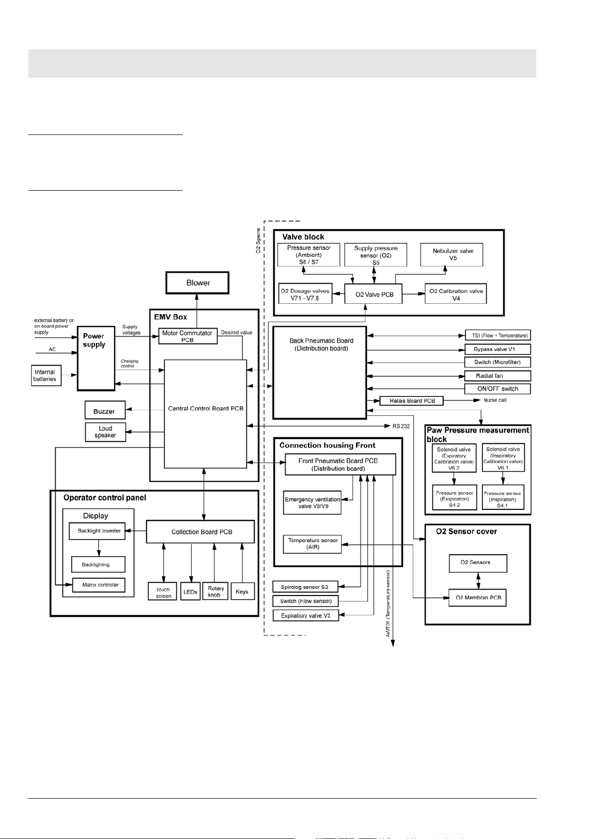
Introduction The following text sets out the block diagram and the functional principle of
the Savina 300.
Block diagram
Fig. 1 Block diagram Savina 300
10
No.1309_0000001227_Publication
Savina 300
Page 11

Function descriptions
Block diagram and functional principle
Functional principle The blower generates the necessary compressed air for ventilation. A con-
trollable valve (non-return valve) is switched in parallel with the blower to regulate the pre-set ventilation parameter. The non-return valve opens or closes
according to the pre-set ventilation parameters.To increase the oxygen concentration in the ventilation gas, an external oxygen source can be connected
to the device. Sensors, the electronics and the valve block meter the oxygen
concentration.
Main components The device consists of the following main components:
– Elektronic assembly
– Control unit
– Pneumatic assembly
No.1309_0000001227_Publication
Savina 300
11
Page 12

Function descriptions
Electronic assembly
Electronic assembly
Introduction The electronic assembly contains the following subassemblies:
– Power supply unit
– Central Control Board
– Motor actuator
–O2 Valve PCB
– O2 Diaphragm PCB
– Fan
Power supply unit The power supply unit delivers the supply voltages for the device. The input
voltage range is 100 V to 240 V AC and 50 Hz to 60 Hz. The power supply
unit can also be operated with an external rechargeable battery (12 V or
24 V).
The connection to the alternating voltage is made by a power cable. The connection for the external rechargeable battery is made by an encoded connector.
The power supply unit actuates the „Mains power“, „External battery or onboard power supply“ and „Internal battery“ LEDs. The LEDs are mounted on
the membrane keypad of the control panel and indicate the respective operating status.
The device includes two internal rechargeable batteries (2 x 12 V) which
enable uninterrupted operation in the event of a mains power failure. The
internal rechargeable batteries supply the O2 sensors with power even when
the device is switched off. When the device is switched on the valid O2 values are present.
The power supply unit generates the following supply voltages:
–+5 V
–-15 V
–+15 V
–+24 V
–+48 V
The output voltages are short-circuit-proof and stable at no-load.
12
The output voltages are generated according to the following priority, dependent on the input voltages:
Input voltage Priority Action
AC voltage 1 Charge external and internal batteries, and maintain the
charge.
External battery/batteries 2 Charge internal batteries, and maintain the charge.
Internal batteries 3 -
No.1309_0000001227_Publication
Savina 300
Page 13
Function descriptions
Electronic assembly
The fan cools the power pack.
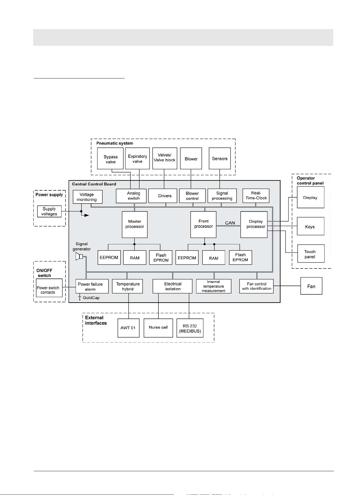
Central Control Board The Central Control Board is the device's central „control and monitoring
unit“. It has three separate processor systems (master processor, front processor and display processor).
Three processor systems save the changeable, non-volatile data to
EEPROMs.
Fig. 2 Block diagram of the Central Control Board
Master processor
The master processor has the following tasks:
– Activation of the actuators (valves, valve block, blower)
– Reading of the measured values from the sensors
– Control of the ventilation
– Monitoring of the front processor
The master processor data are cached in the RAM.
The EEPROM of the master processor system stores the calibration data of
the sensors and set values such as volume.
No.1309_0000001227_Publication
Savina 300
13
Page 14

Function descriptions
Electronic assembly
Front processor
The front processor has the following tasks:
– Interface with the display processor
– Monitoring of the master processor and display processor
– Monitoring of the input logic and the data e.g. the pixel sum
The RAM caches data from the front processor.
The EEPROM with socket of the front processor stores safety parameters,
set values such as volume, software options and the operating hours.
Display processor
The display processor has the following tasks:
– Presentation of curves and parameters on the display, LEDs
– Input and operator data (keyboard, rotary encoder, touchscreen)
– Collation of data such as the pixel sum.
The EEPROM of the display processor stores user-specific display settings,
such as measured value positions.
Flash EEPROMs
The device's operating system program (software) is stored in Flash
EEPROMs (rewritable memory modules).
Real-time clock
The real-time clock generates the time and date information. The real-time
clock has an internal battery.
The Central Control Board incorporates the following functions:
– Processing of the signals from the sensors (O2, flow, pressure, tempera-
ture)
– Control of the blower and valves
– Monitoring of the unit functions and the supply voltages
– Actuation of the displays
– Keypad interpretation
– Provision of the internal and external interfaces
– Set values such as the volume
14
Mains power failure alarm
If the mains power fails, the device switches to the internal batteries which
supply the device with power. If the internal batteries are discharged and the
device has no external batteries, an acoustic alarm is sounded with a GoldCap and a horn.
No.1309_0000001227_Publication
Savina 300
Page 15
Function descriptions
Electronic assembly
Temperature hybrid
The temperature hybrid reads the data of the AWT01 sensor and converts
these into digital signals. An electrical isolation occurs in this process.
Internal temperature measurement
The internal temperature measurement is a safety function. In the event of
overheating (if the internal temperature of the device is too high), an alarm is
sounded.
Fan actuation and fans
The fan rotates quickly after the device has been switched on to remove any
residual oxygen from the device. The rotation of the fan is detected and controlled in three stages (slow, medium and fast).
Three temperature sensors control the fan.
CAN
The CAN interface is a fast, serial interface. Via the CAN interface the control
unit can communicate with the electronic and pneumatic assemblies. The
transmission rate is 800 kbit/s.
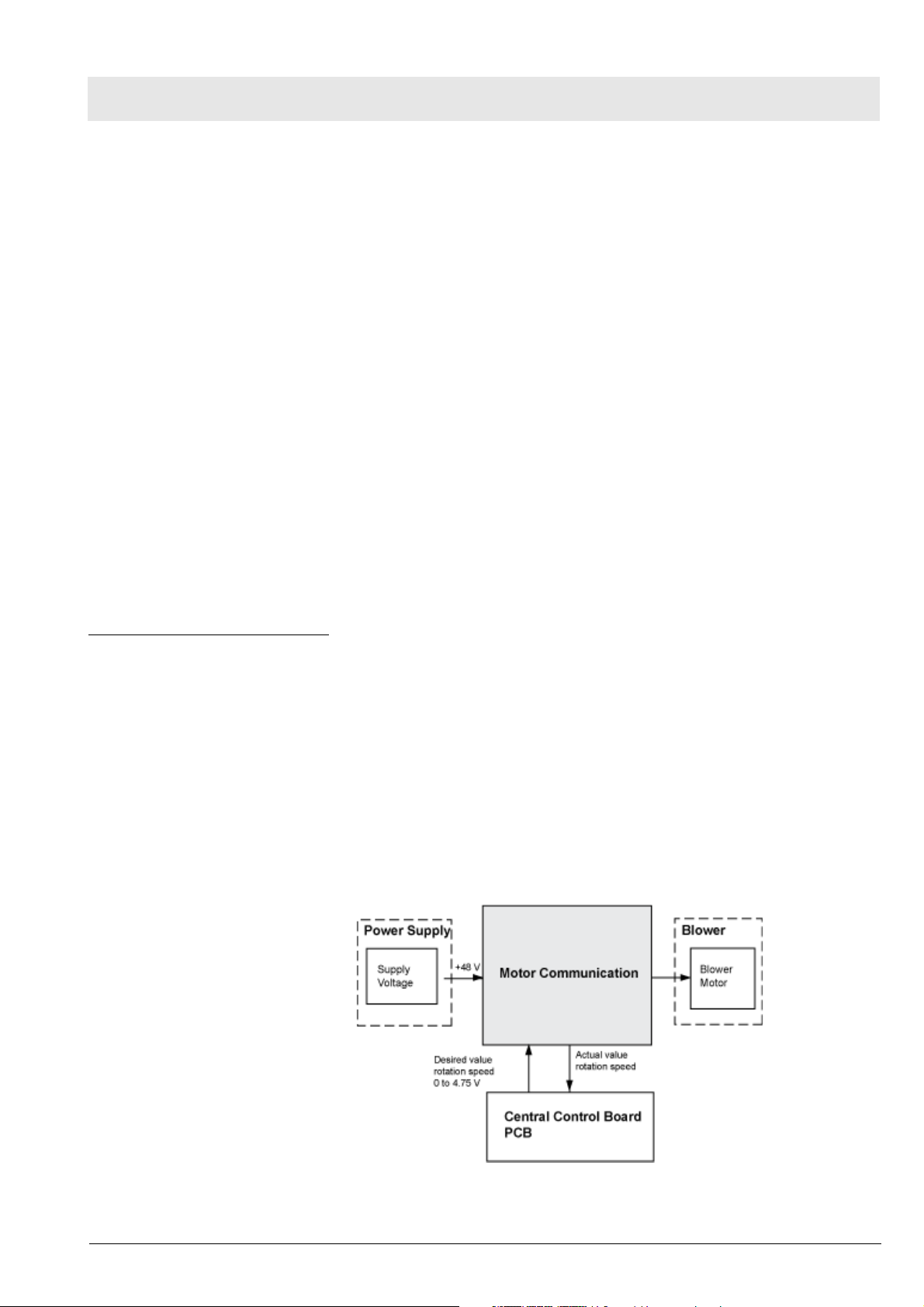
Motor actuator The motor actuator controls the blower motor. The motor actuator is located
in a self-contained housing. The supply voltage for the motor actuator is +48
V and is protected by a fuse (6.3AT).
The input voltage range of the motor actuator is 12 to 52.5 V. The rotation
speed is set by the Central Control Board. The control voltage for the rotation
speed is 0 V to +5.00 V, corresponding to a rotation speed of 0 to 12,000 rpm.
The rotation speed range is 4,000 to 12,000 rpm.
The motor actuator acquires the „actual speed signal“ and forwards it to the
Central Control Board. The „actual value signal“ is 6 pulses per rotation. In
the event of discrepancies in the rotation speed the Central Control Board
adjusts the speed according to the deviation.
Fig. 3 Block diagram of the motor actuator
No.1309_0000001227_Publication
Savina 300
15
Page 16
Function descriptions
Electronic assembly
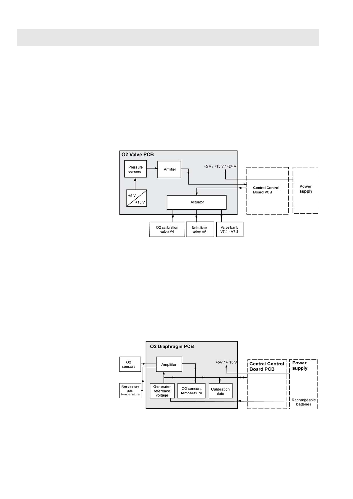
O2 Valve PCB The O2 Valve PCB holds the pressure sensors (absolute pressure S6 and S7
and O2 supply pressure S5), the actuator for the O2 calibrating valve and the
nebulizer valve and the actuator for the valve block.
The signals of the pressure sensors are amplified and routed to the Central
Control Board. The supply voltage (+5 V) for the pressure sensors is generated by the O2 Valve PCB.
The valve block valves, the O2 calibrating valve and the nebulizer valve can
be operated separately by an electronic switch. They are actuated by the
Central Control Board.
Fig. 4 Block diagram of the O2 Valve PCB
O2 Diaphragm PCB The O2 Diaphragm PCB amplifies the signals from the O2 sensors and mea-
sures the temperature of the O2 sensors and of the respiratory gas in the
inspiration block. The temperature of the O2 sensors is required to compensate for the temperature-sensitive O2 measurements. The EEPROM on the
Central Control Board stores the calibration data of the sensors. The reference voltage for the O2 sensors is generated from the voltage of the
rechargeable batteries.
The supply voltages for the O2 Diaphragm PCB are +5 V and +15 V.
16
Fig. 5 O2 Diaphragm PCB block diagram
No.1309_0000001227_Publication
Savina 300
Page 17
Function descriptions
Electronic assembly
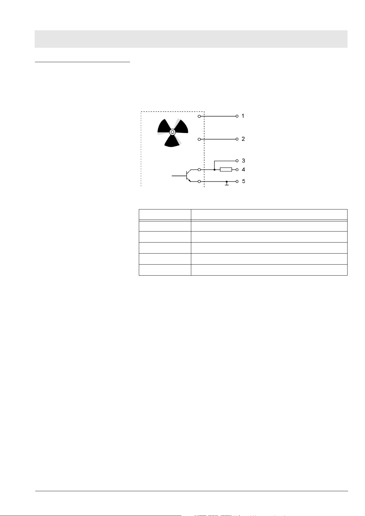
Fan The fan takes in ambient air through the cooler and cools the blower motor.
The air flow removes excess oxygen from the device.
The supply voltage for the fan is +24 V. The Central Control Board regulates
the speed of the fan.
Fig. 6 Fan control
Item Designation
1 Supply voltage
2 Target speed
3 Speed signal
4 Sensor supply voltage
5 Ground
No.1309_0000001227_Publication
Savina 300
17
Page 18
Function descriptions
Control panel with TFT colour display
Control panel with TFT colour display
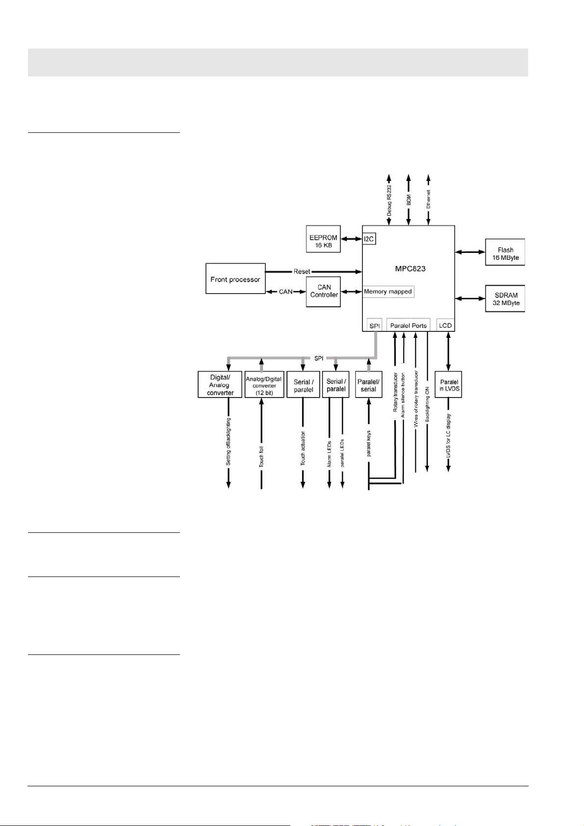
Control unit The control panel is the interface between the unit and the user. The control
panel is used to enter and display the ventilation parameters.
Fig. 7 Block diagram of the control panel with TFT colour display
Membrane keypad The keypad features the control keys and the associated LEDs.
TFT colour display The 12.1” TFT colour display comprises the actual display and the backlight
converter. The TFT colour display has a resolution of 800 x 600 pixels.
The backlight converter generates a high voltage for the display backlighting.
Rotary encoder The rotary knob is used to set and acknowledge the ventilation parameters.
The shaft encoder transmits square signals to the processor system as it
rotates, and the signals are then evaluated by the Central Control Board. The
voltage supply is +5 V.
No.1309_0000001227_Publication
18
Savina 300
Page 19
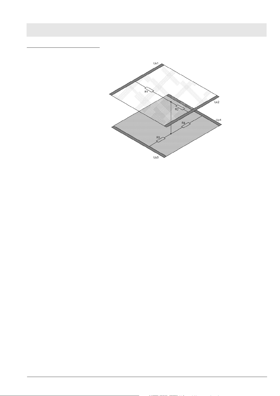
Touch-panel Analog-resistive touch-screen
Function descriptions
Control panel with TFT colour display
Fig. 8 Analog-resistive touch-screen
Analog systems consist of two opposing conductive indium tin oxide (ITO)
layers (x and y layer) which are actuated with a constant direct voltage.
Indium tin oxide is a transparent semiconducting material.
Between the two ITO layers there are a large number of small, barely visible
so-called spacer dots which ensure the two layers are kept separate.
In 8-wire systems the touch-screen has eight wires routed to the controller –
four for each axis.
When the touch-screen is touched at a certain point where the two ITO layers
are located an electrical contact is produced. The resistance of this contact
results in a different voltage at each point. The change in voltage is then used
to define the x and y coordinates.
The Central Control Board controls the communication between the processor system and the touch-screen. The correct position is determined with the
aid of the relevant software drivers. The analog touch-screen works very precisely, and provides a high resolution.
No.1309_0000001227_Publication
Savina 300
19
Page 20
Function descriptions
Pneumatic assembly
Pneumatic assembly
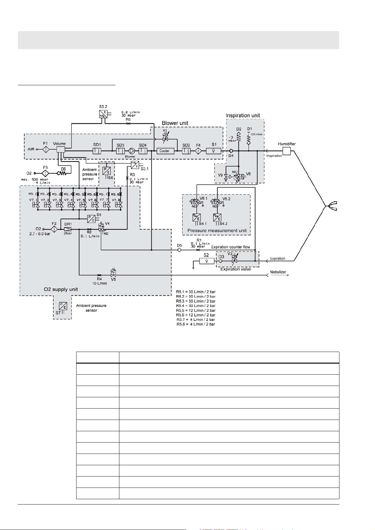
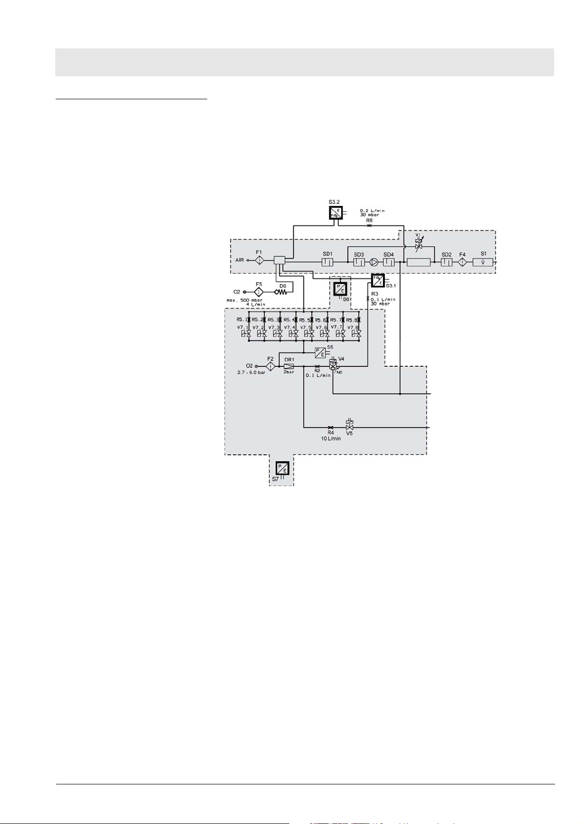
Functional diagram
Fig. 9 Functional diagram
Item Designation
F1 Micro-filter (AIR)
F2 Filter (O2)
F4 Filter (inspiratory flow sensor)
F5 Filter (Filter element)
Volume Mixing chamber
SD1 Suction sound insulator
SD2 Sound insulator
DR1 Supply pressure regulator (Oxygen)
Gebläse Blower
Kühler Cooler
V1 Reduction valve
V3 Expiratory valve
20
No.1309_0000001227_Publication
Savina 300
Page 21

Function descriptions
Pneumatic assembly
Item Designation
V4 Switching valve (oxygen compensation)
V5 Switching valve (nebulizer)
V6.1 Calibration valve (inspiratory airway pressure sensor)
V6.2 Calibration valve (expiratory airway pressure sensor)
V7.1 - V7.8 Oxygen metering valves
V8 Pilot valve for emergency vent valve
V9 Emergency vent valve
S1 Inspiratory flow sensor
S2 Expiratory flow sensor
S3.1 O2 sensor 1 (measurement and control)
S3.2 O2 sensor 2 (Monitoring)
S4.1 Inspiratory airway pressure sensor (located in inspiratory branch)
S4.2 Expiratory airway pressure sensor (located in expiratory branch)
S5 Supply pressure sensor (oxygen)
S6 Pressure sensor 1 (absolute pressure)
S7 Pressure sensor 2 (absolute pressure)
D1 Safety pressure-limitting valve (passive, approx. 120 mbar)
D2 Emergency air valve (-3 mbar to -6 mbar)
D3 Expiratory non-return valve
D4 Inspiratory non-return valve
D5 Flush flow non-return valve
D6 Non-return valve (LPO)
R1 Flush flow metering unit (0,1 L/min at 30 mbar)
R2 O2 calibration metering unit for (0,1 L/min, integrated in valve block)
R3 Metering unit for O2 measurement (0,2 L/min at 30 mbar, Sensor 3.1)
R4 Metering unit for nebulizer (10 L/min, integrated in valve block)
R5.1 - R5.8 Metering units for the oxygen metering valves
R6 Metering unit for O2 measurement (0,2 L/min at 30 mbar, Sensor 3.2)
Main components The pneumatic assembly consists of the following components:
– Plug-in unit
– Valve block
– Inspiratory block
– Pressure measuring block
– Patient system
– Flow sensors
No.1309_0000001227_Publication
Savina 300
21
Page 22
Function descriptions
Pneumatic assembly
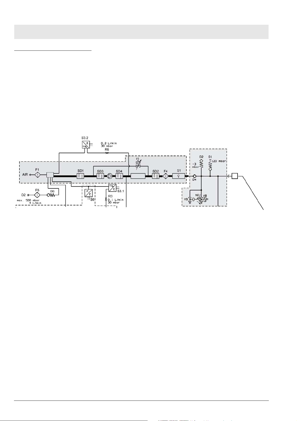
Device functions
Ventilation function When the device is switched on the power supply unit supplies the blower
motor with operating voltage. The blower motor draws in ambient air through
the microfilter F1, the volume and the sound insulators SD1 and SD3. The
blower motor compresses the gas intake to an overpressure up to max. 140
mbar at a delivery rate of up to 180 L/min. The air compressed by the blower
motor passes through the sound insulator SD4, the cooler, the sound insulator SD2, the filter F4 and the inspiratory flow sensor S1 to the inspiratory nonreturn valve D4. The controller operates the blower motor during a breath at a
constant speed. The bypass valve regulates the inspiratory pressure. The
combination of the blower motor and bypass valve V1 provides a pressure
source.
Fig. 10 Detail view of functional diagram; ventilation function
The sound insulators SD1 and SD2 on the inlet and outlet sides of the blower
motor reduce the sound level.
The bypass valve V1 is operated such that the desired respiratory pressure is
applied to the blower outlet, and thus to the patient. If the patient needs a high
flow during the inspiratory phase, the gas flows in part or in its entirety from
the blower motor outlet to the patient and the gas flow through the bypass
valve V1 is reduced. During the expiratory phase all the blower gas flows
through the bypass valve V1.
The cooler reduces the respiratory gas temperature down to a permissible
range.
22
No.1309_0000001227_Publication
Savina 300
Page 23
Function descriptions
Pneumatic assembly
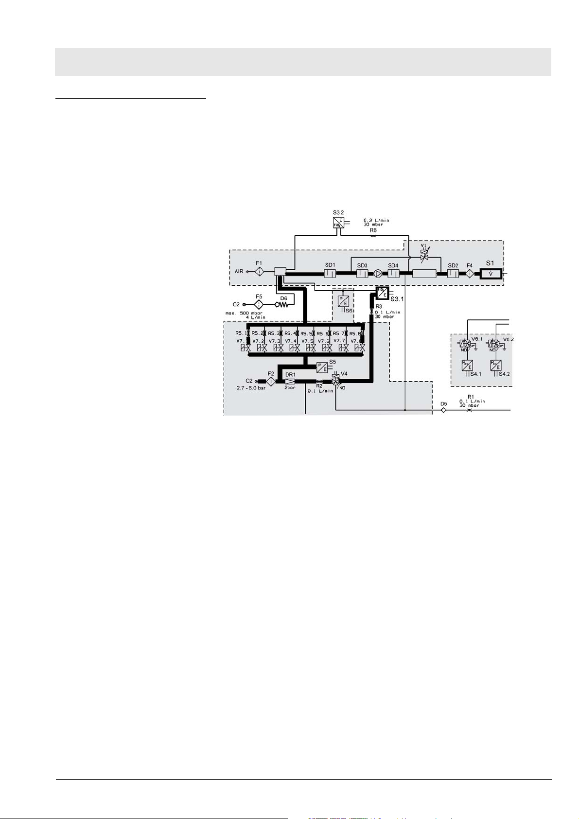
O2 mixture with O2 high
pressure
In order to be able to ventilate with an increased O2 concentration, the unit
must be supplied with 2.7 to 6.0 bar O2. The oxygen is filtered by the filter F2.
With the aid of the digital valve block consisting of 8 digital solenoid valves,
oxygen is metered into the volume (mixing chamber). The amount of metered
oxygen depends on the pre-set O2 concentration and on the inspiratory flow
rate measured by the flow sensor S1. The oxygen is metered in a closed control loop. In the process, the inspiratory O2 concentration is measured by the
O2 sensor S 3.1.
Fig. 11 Detail view of functional diagram; O2 mixture with O2 high pres-
sure
No.1309_0000001227_Publication
Savina 300
23
Page 24
Function descriptions
Pneumatic assembly
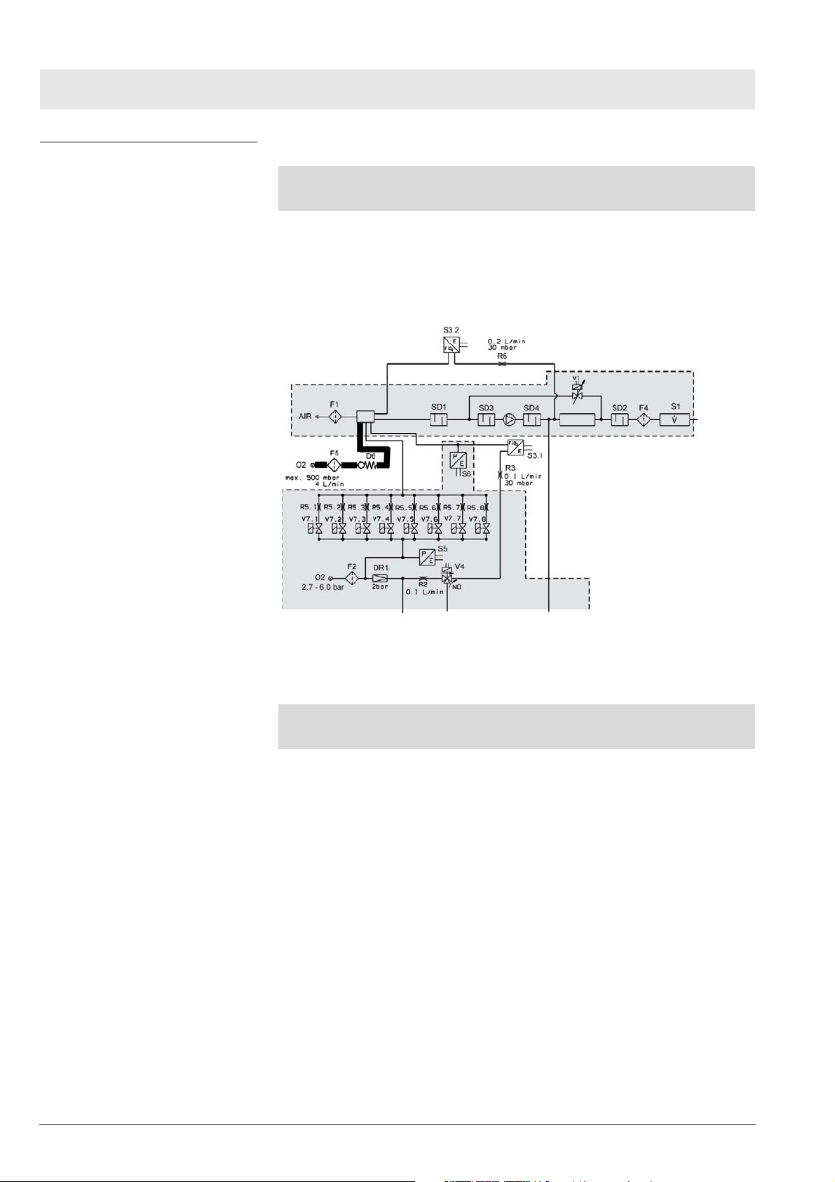
O2 mixture with O2 low
pressure („LPO“ option)
NOTE
Connect only O2 low pressure sources without humidifier to the device!
An O2 low pressure source without humidifier feeds the oxygen into the
“LPO” connection on the back of the unit. The filter (filter element) F5 protects
the non-return valve D6 from coarse particles. The oxygen flows from the
non-return valve D6 into the volume (mixing chamber). In the volume (mixing
chamber) it is mixed with the drawn-in and filtered fresh air.
Fig. 12 Detail view of functional diagram; O2 mixture with O2 low pressure
When no O2 low pressure source is connected to the unit, the non-return
valve D6 prevents gas from escaping during normal operation.
NOTE
In „LPO“ mode, the valve block in the O2 supply is not actuated.
24
No.1309_0000001227_Publication
Savina 300
Page 25
Function descriptions
Pneumatic assembly
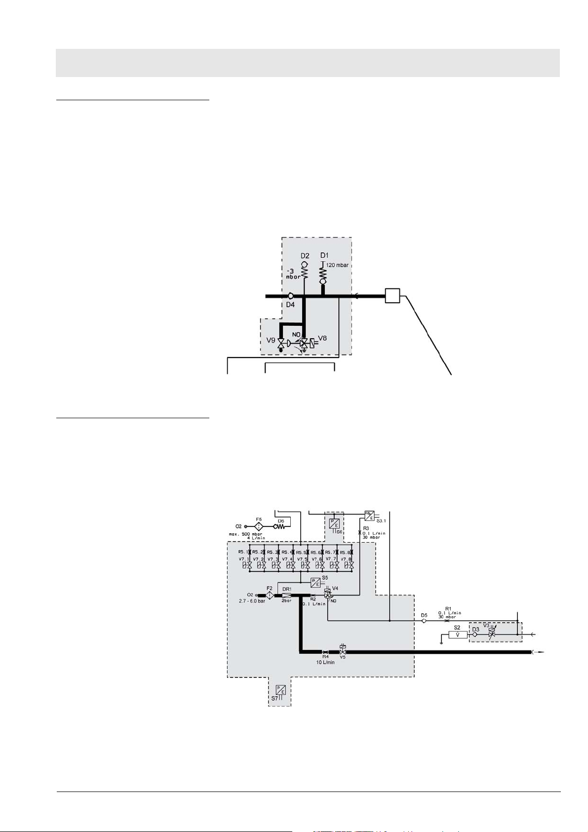
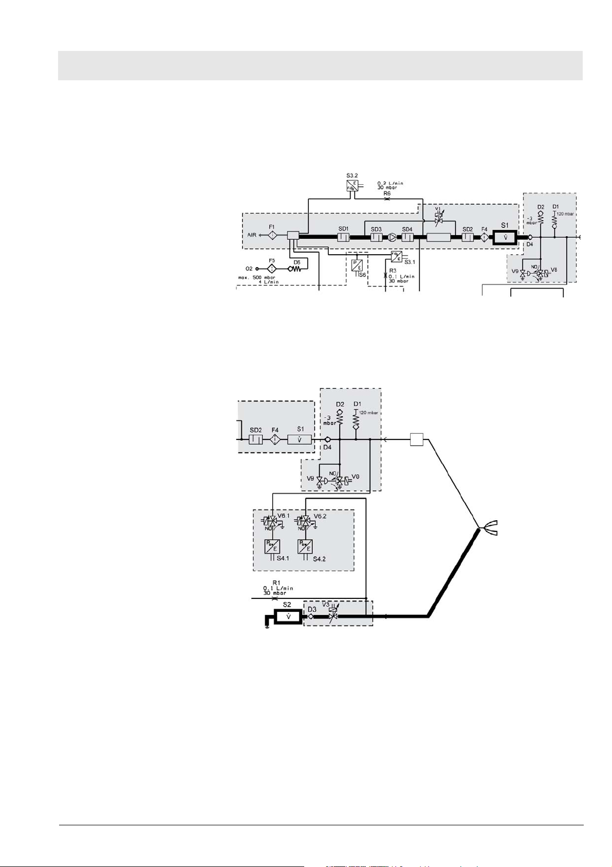
Pneumatic safety devices The pneumatic safety valve D1 ensures that the ventilation pressure cannot
rise above 120 mbar. In the event of inspiratory stenosis the pressure is limited by opening the expiratory valve. The mechanical vacuum valve D2
ensures (except in the case of inspiratory stenosis) that the patient can
breathe ambient air in case of a fault.
The pneumatic emergency vent valve V9 relieves the pressure in the breathing system in a case of expiratory stenosis if the pressure cannot be relieved
through the expiratory valve. To do so, the electric emergency vent valve
(pilot valve) V8 actuates the emergency vent valve V9 accordingly.
Fig. 13 Detail view of functional diagram; pneumatic safety devices
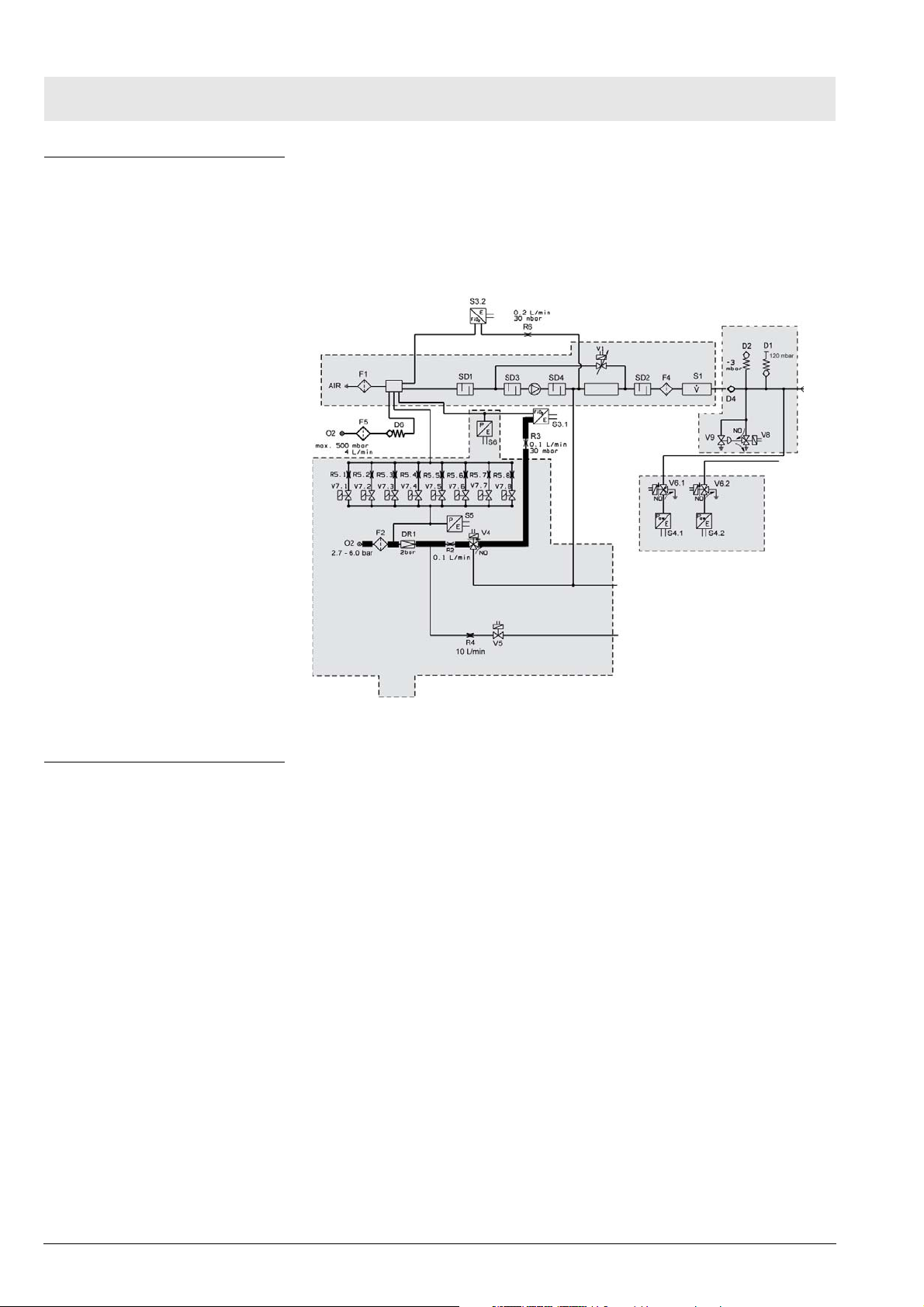
Drug nebulizer The drug nebulizer is operated with 100% oxygen. The pressure regulator
DR1 ensures in the case of widely varying supply pressure (2.7 to 6.0 bar)
that the pneumatic drug nebulizer receives a constant supply pressure of
2 bar.During the nebulizing phase the solenoid valve V5 operates in an “inspiration” (open position) and “expiration” (closed position) cycle. When the nebulizer function is inactive the nebulizer switching valve V5 is closed.
Fig. 14 Detail view of functional diagram; drug nebulier
No.1309_0000001227_Publication
Savina 300
25
Page 26
Function descriptions
Pneumatic assembly
O2 calibration function During operation, the switching valve (oxygen compensation) V4 is set to
“measurement” – that is, the connection between the inspiratory side and the
oxygen sensor is open. During oxygen sensor calibration oxygen passes to
the oxygen sensor. This layout permits “online” calibration of the oxygen sensor S3.1 during ventilation. The oxygen sensor S3.2 must be calibrated manually (patient disconnected).
Fig. 15 Detail view of functional diagram; O2 calibration function
O2 sensor detection The device has an oxygen sensor detector which is necessary for the „LPO“
option.
26
No.1309_0000001227_Publication
Savina 300
Page 27
Function descriptions
Pneumatic assembly
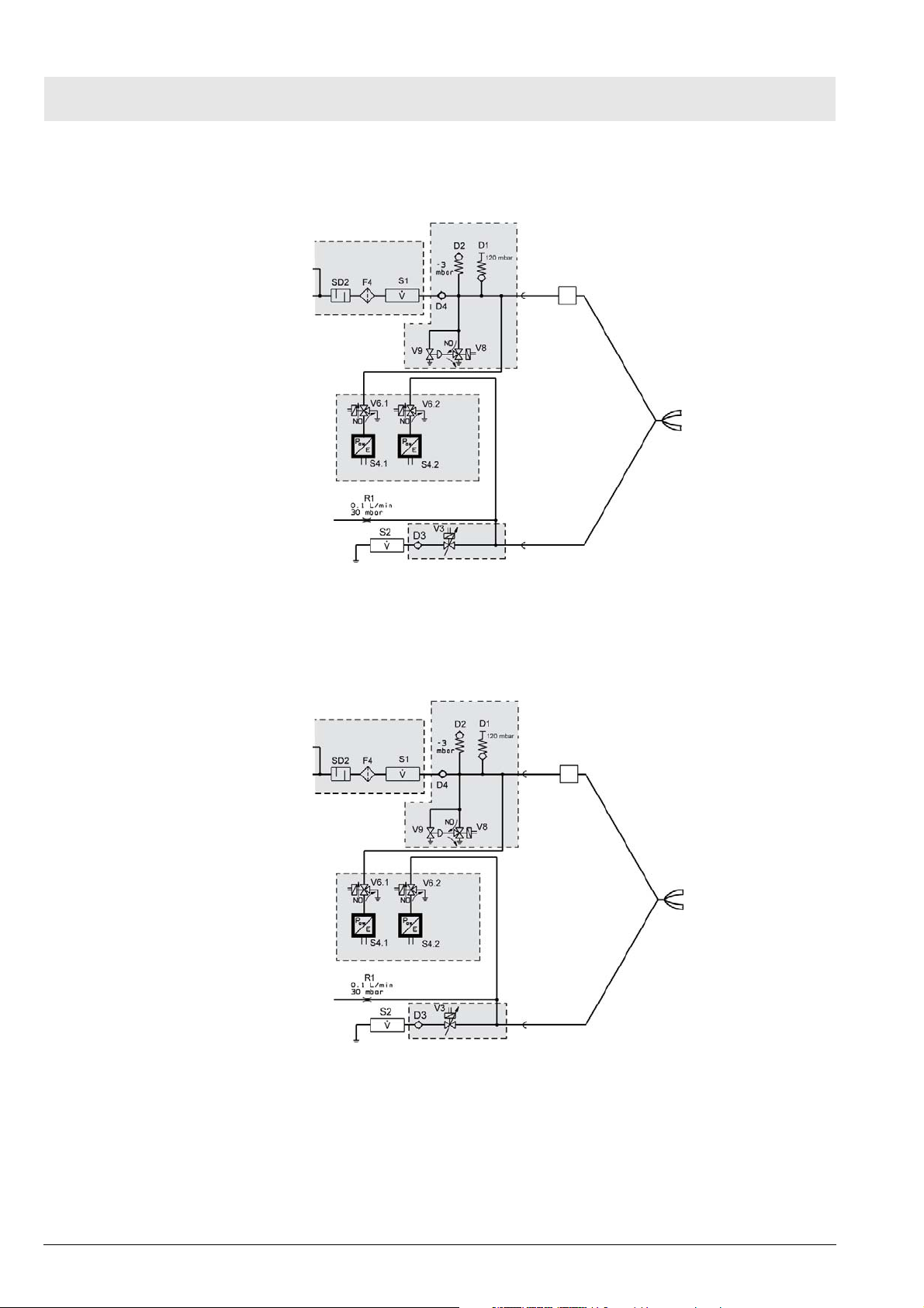
Sensors The pressure sensor (absolute pressure) S6 measures the atmospheric pres-
sure necessary for oxygen measurement and for volume application. The
pressure sensor (absolute pressure) S7 monitors the pressure sensor (absolute pressure) S6.The oxygen sensor S3.1 generates the signal for the displayed „FiO2“ measured value and the signal to control the inspiratory
oxygen concentration. The oxygen sensor S3.2 monitors the oxygen sensor
S3.1
Fig. 16 Detail view of functional diagram; pressure sensors and oxygen
sensor
The airway pressure sensor S4.1 measures the pressure in the inspiratory
branch. The airway pressure sensor S4.2 measures the pressure in the expiratory branch. The output signals of the airway pressure sensors are needed
No.1309_0000001227_Publication
Savina 300
27
Page 28
Function descriptions
Pneumatic assembly
to determine the airway pressure and for control and monitoring purposes.
The airway pressure is measured on the basis of the measured value from
the airway pressure sensor in the respective no-flow branch.
Fig. 17 Detail view of functional diagram; airway pressure sensors
The calibration valves V6.1 and V6.2 enable calibration of the inspiratory and
expiratory airway pressure sensors. During calibration, the corresponding
calibration valve interrupts the connection to the ventilation circuit and
switches the airway pressure sensor to ambient pressure.
28
Fig. 18 Detail view of functional diagram; calibration valves
No.1309_0000001227_Publication
Savina 300
Page 29
Function descriptions
Pneumatic assembly
Flow sensor S1 measures the inspiratory gas flow. The measurement variable is used to calculate the necessary oxygen flow and to actuate the oxygen metering valves V7.1 to V7.8 in order to control the breaths and monitor
the device functions. The flow sensor includes a temperature measurement
function to measure the inspiratory gas temperature.
Fig. 19 Detail view of functional diagram; flow sensor
The flow sensor S2 measures the gas flow through the expiratory valve. The
flow sensor is a temperature-compensated hot-wire anemometer with no flow
direction detector. With this signal the patient is monitored (e.g. the minute
volume).
Fig. 20 Detail view of functional diagram; flow sensor
Expiration is executed with the directly actuated expiratory valve V3.
The expiratory valve has the following functions:
– PEEP control during the expiratory phase
– Close the breathing system during the inspiratory phase.
No.1309_0000001227_Publication
Savina 300
29
Page 30

– This page has been intentionally left blank –
30
No.1309-0000001227_Publication
Savina 300
Page 31

Maintenance instructions
This chapter describes the measures required to maintain the specified con-
dition of the device.
Disassembling/assembling the device ...............................................................................................
Replacing the microfilter ....................................................................................................................
Replacing the dust filters....................................................................................................................
Replacing the O2 sensors..................................................................................................................
Replacing the diaphragm of the expiratory valve...............................................................................
Replacing the internal batteries .........................................................................................................
Replacing the external batteries ........................................................................................................
Replacing the consumables in the O2 gas inlet.................................................................................
32
38
40
42
47
50
54
65
No.1309_0000001227_Publication
Savina 300
31
Page 32

Maintenance instructions
Disassembling/assembling the device
Disassembling/assembling the device
Introduction This section describes how to disassemble and assemble the following
assemblies:
– Removing/fitting the Savina 300 from/into the trolley
– Filter cover
– Rear panel
Removing/fitting the
Savina 300 from/into the
trolley
Preconditions – The O2 and mains power supply to the Savina 300 have been cut.
– The tubing system and fitted units have been removed.
Removal 1. Loosen the nuts (Fig. 21/1) on the left and right sides of the trolley slightly
and push the two locking devices (Fig. 21/2) inwards towards A as far as
they will go.
2. Remove the screws (Fig. 21/3).
32
Fig. 21 View from below of trolley mount; screws
No.1309_0000001227_Publication
Savina 300
Page 33

Maintenance instructions
Disassembling/assembling the device
3. Lift the Savina 300 out of the trolley.
Installation 1. Place the Savina 300 in the trolley.
2. Use the screws (Fig. 22/3) to secure the Savina 300 to the trolley.
3. Push the locking devices (Fig. 22/2) on the left and right sides of the trol-
ley outwards towards B as far as they will go and tighten the nuts (Fig.
22/1).
Fig. 22 View from below of trolley mount; screws
No.1309_0000001227_Publication
Savina 300
33
Page 34

Maintenance instructions
Disassembling/assembling the device
Filter cover
Removal 1. Withdraw the power cable (Fig. 23/2) from filter cover guide.
2. Reach into the openings in the filter cover on both sides, press the
catches concealed behind them (Fig. 23/1) simultaneously towards A
slightly, move the filter cover back slightly and take the filter cover out of
the rear panel.
Fig. 23 View of device rear; filter cover
Removal of the filter cover is complete.
Installation 1. Slot the tabs (Fig. 24/1) of the filter cover into the recesses (Fig. 24/2) in
the rear panel, swivel the filter cover upwards and press the catches (Fig.
23/1) of the filter cover into the rear panel until they lock in place.
34
Fig. 24 Detail view of filter cover; tabs and recesses
2. Lay the power cable (Fig. 23/2) around the filter cover guide, as shown in
the illustration.
Fitting of the filter cover is complete.
No.1309_0000001227_Publication
Savina 300
Page 35

Rear panel
Preconditions – Savina 300 has been disconnected from the O2 supply and the mains
Removal 1. Pry the tab fuse (Fig. 25/2) from its holder using a small screwdriver or
Maintenance instructions
Disassembling/assembling the device
power supply.
– The tubing system and units mounted on the Savina 300 have been
removed.
– EGB conditions to protect against electrostatic discharge have been
established.
– The filter cover has been removed, see section headed „Filter cover“.
similar tool.
2. Remove the connectors and tubing listed below from the Savina 300, if
fitted:
Fig. 25 View of device rear; connections
Item Designation
1 Connection (external battery)
2 Tab fuse
3 Mains connection
4 Connection (nurse call)
5 Connection (RS232 port)
6 Connection for LPO (option)
7 Connection (O2 gas supply)
Connector for potential equalization
No.1309_0000001227_Publication
Savina 300
35
Page 36

Maintenance instructions
Disassembling/assembling the device
3. Holding the lever (Fig. 26/2) pushed back slightly, push the cable retainer
(Fig. 26/1) towards A and take it out of the rear panel.
Fig. 26 View of right rear of device; cable retainer
4. Remove the Savina 300 from the trolley, see section headed „Removing/fitting the Savina 300 from/into the trolley“.
5. Remove the screws (9x) (Fig. 27/1).
Fig. 27 View of device rear; screws
36
6. Remove the rear panel.
Removal of the rear panel is now complete.
No.1309_0000001227_Publication
Savina 300
Page 37

Maintenance instructions
Disassembling/assembling the device
Installation 1. Fit the rear panel to the Savina 300 using the screws (Fig. 27/1) tightened
with a torque of 1.8 Nm +/-0.2 Nm.
2. Fit the cable retainer (Fig. 26/1) in the rear panel.
3. Fit the Savina 300 into the trolley, see section headed „Removing/fitting
the Savina 300 from/into the trolley“.
4. Re-attach removed connectors and tubing to the Savina 300.
5. Fit the filter cover on the Savina 300, see section headed „Filter cover“.
6. Plug the tab fuse for the internal batteries into the holder on the power
supply unit.
7. Perform the „electrical safety test“ and „function tests“ as per the test
instructions.
Fitting of the rear panel is complete.
No.1309_0000001227_Publication
Savina 300
37
Page 38

Maintenance instructions
Replacing the microfilter
Replacing the microfilter
Introduction The following section provides a view of the microfilter and describes how to
remove and fit it.
View The microfilter (Fig. 28/1) is located on the rear of the device.
Removal
Preconditions – Savina 300 is switched off.
Procedure 1. Reach into the openings in the filter cover on both sides, press the
Fig. 28 Device rear; microfilter
catches concealed behind them (Fig. 29/1) simultaneously towards A
slightly, move the filter cover back slightly and take the filter cover out of
the rear panel.
2. Withdraw the power cable (Fig. 29/2) from filter cover guide.
38
Fig. 29 Savina 300 rear; filter cover
No.1309_0000001227_Publication
Savina 300
Page 39

Maintenance instructions
Replacing the microfilter
3. Withdraw the microfilter (Fig. 30/2) by the tab (Fig. 30/1) out of its mount
and dispose of it in the domestic waste bin.
Fig. 30 Savina 300 rear; microfilter
Removal of the microfilter is complete.
Fitting 1. Insert the new microfilter (Fig. 30/2) into its mount as far as it will go.
2. Close the tab (Fig. 30/1) against the microfilter.
3. Slot the pegs on the underside of the filter cover into the recesses in the
rear panel, swivel the filter cover upwards and with the catches (Fig. 29/1)
press the filter cover into the rear panel until it locks in place.
4. Lay the power cable (Fig. 29/2) around the filter cover guide, as shown in
the illustration.
Fitting of the microfilter is complete.
No.1309_0000001227_Publication
Savina 300
39
Page 40

Maintenance instructions
Replacing the dust filters
Replacing the dust filters
Introduction The following section provides a view of the dust filter set and describes how
to remove and fit it.
View The dust filters (Fig. 31/1) are located in the device's filter cover.
Fig. 31 Device rear; dust filters (3x)
Removal 1. Reach into the openings in the filter cover on both sides, press the
catches concealed behind them (Fig. 32/1) simultaneously towards A
slightly, move the filter cover back and take the filter cover out of the rear
panel.
2. Withdraw the power cable (Fig. 32/2) from filter cover guide.
Fig. 32 Savina 300 rear; filter cover
40
No.1309_0000001227_Publication
Savina 300
Page 41

Maintenance instructions
Replacing the dust filters
3. Withdraw the dust filters (Fig. 33/1) out of the filter cover and dispose of
them in the domestic waste bin.
Fig. 33 Filter cover; dust filters (3x)
Removal of the dust filters is complete.
Fitting 1. Insert the new dust filters (Fig. 33/1) in the recesses in the filter cover.
2. Slot the pegs (Fig. 34/1) on the underside of the filter cover into the
recesses (Fig. 34/2) in the rear panel, swivel the filter cover upwards and
with the catches (Fig. 32/1) press the filter cover into the rear panel until it
locks in place.
Fig. 34 Detail view of filter cover: Fitting
3. Lay the power cable (Fig. 32/2) around the filter cover guide, as shown in
Fitting of the dust filters is complete.
No.1309_0000001227_Publication
Savina 300
the illustration.
41
Page 42

Maintenance instructions
Replacing the O2 sensors
Replacing the O2 sensors
Introduction
NOTE
Replace the O2 sensors if calibration is no longer possible or if the alarm
message „FiO2 measurement failed“ is displayed.
The following section provides a view of the O2 sensors and describes how
to remove, fit and calibrate them.
View The O2 sensors (Fig. 35/1) are located behind the cover plate on the front of
the Savina 300.
Fig. 35 Device front; O2 sensors
No.1309_0000001227_Publication
42
Savina 300
Page 43

Removal
Preconditions – The Savina 300 is switched off and disconnected from the mains power
Maintenance instructions
Replacing the O2 sensors
supply.
Service equipment
– Screwdriver
required
Procedure 1. Swivel the inspiratory port (Fig. 36/1) down.
2. Loosen the screw (Fig. 36/2) using a screwdriver or similar and detach
the cover plate (Fig. 36/3).
Fig. 36 Device front; cover plate
3. Take the O2 sensors (Fig. 37/1) out of their mounts.
Fig. 37 Device front; removing the O2 sensors
NOTE
O2 sensors are special waste. When disposing of them, observe local
waste disposal regulations.
No.1309_0000001227_Publication
Savina 300
43
Page 44

Maintenance instructions
Replacing the O2 sensors
4. Dispose of the O2 sensors according to local waste disposal regulations.
Removal of the O2 sensors is complete.
Fitting 1. Push the O2 sensors (with the arrows on the oxygen cells pointing
upwards, as shown in the following illustration) into their mounts until you
feel a resistance.
Fig. 38 Device front; fitting the O2 sensors
2. Swivel the inspiratory port (Fig. 39/1) down.
3. Use the screw (Fig. 39/2) to secure the cover plate (Fig. 39/3) on the
Savina 300.
Fig. 39 Device front; cover plate
44
Fitting of the O2 sensors is complete.
No.1309_0000001227_Publication
Savina 300
Page 45

Calibrating the O2 sensors
Preconditions – The Savina 300 has been connected to the mains power supply.
Calibrating O2 sensor 2 in
„HPO“ mode
Maintenance instructions
Replacing the O2 sensors
– The blade fuse has been has been inserted into the slot on the power
supply unit.
– The Savina 300 has been connected to the O2 supply.
NOTE
To be able to calibrate the Savina 300 correctly, you must wait for the
device to warm up. If the blade fuse was removed, it may take as long as
20 minutes for the device to warm up.
CAUTION
If the quality of the oxygen from the central oxygen supply or the compressed gas oxygen cylinder is inadequate, calibrate the O2 sensor with
calibration gas (100% O2). Otherwise miscalibration may occur.
1. Switch on the Savina 300.
2. Set „VC-CMV/VC-AC“ mode.
3. Press the „Sensors/Parameters“ softkey.
4. Press the O2 calibration „Start“ softkey and confirm with the rotary knob.
The message „Disconnect patient“ is displayed.
5. Within the next 30 seconds detach the inspiratory tube from the inspiratory socket.
The message „O2 calibration in progress“ is displayed.
6. Detach the inspiratory tube from the inspiratory socket and, if necessary,
continue ventilation with an independent ventilator.
The Savina 300 calibrates O2 sensor 2. During calibration the alarms which
would normally occur due to the disconnection and the changed O2 concentration are disabled. After about 60 seconds the prompt „Reconnect patient“
is displayed.
NOTE
If the patient has not been reconnected after 30 seconds, Savina 300 starts
ventilating again in the preset ventilation mode and all alarms are enabled
again.
7. Immediately fit the inspiratory tube on the inspiratory socket.
NOTE
If the message „FiO2 measurement failed“ is displayed after calibrating, the
O2 sensors must be replaced – see „Replacing the O2 sensors“.
If the display indicates „O2 calibration OK“, calibration is complete.
No.1309_0000001227_Publication
Savina 300
45
Page 46

Maintenance instructions
Replacing the O2 sensors
Calibrating the O2 sensors
in „LPO“ mode
NOTE
In „LPO“ mode the O2 sensors are calibrated with ambient air. The O2
measurement accuracy is reduced as a result. If high O2 measurement
accuracy is required, the O2 sensors must be calibrated in „HPO“ mode.
1. In the situations listed below the O2 sensors cannot be calibrated in
„LPO“ mode:
a) During the 10-minute warm-up phase after switching on the
Savina 300
b) Up to one hour after the Savina 300 has been subjected to a major
temperature change, such as being transported from a cold room to a
heated room or due to extreme ventilation settings.
FiO2 measurement is possible during this time as long as no relevant alarm
is indicated.
2. Press the „Sensors/Parameters“ softkey.
3. Press the O2 calibration „Start“ softkey and confirm with the rotary knob.
4. When prompted by the Savina 300, disconnect the O2 concentrator and
confirm with the rotary knob.
The message „Disconnect patient“ is displayed.
5. Detach the inspiratory tube from the inspiratory socket and, if necessary,
continue ventilation with an independent ventilator.
The display indicates „O2 calibration in progress“. The Savina 300 calibrates
the O2 sensors. During calibration the alarms which would normally occur
due to the disconnection and the changed O2 concentration are disabled.
After about 60 seconds the prompt „Reconnect patient“ is displayed.
6. Immediately fit the inspiratory tube on the inspiratory socket.
NOTE
If the patient has not been reconnected after 30 seconds, Savina 300 starts
ventilating again in the preset ventilation mode and all alarms are enabled
again.
NOTE
If the message „FiO2 measurement failed“ is displayed after calibrating, the
O2 sensors must be replaced – see „Replacing the O2 sensors“.
If the display indicates „O2 calibration OK“, calibration is complete.
46
No.1309_0000001227_Publication
Savina 300
Page 47

Maintenance instructions
Replacing the diaphragm of the expiratory valve
Replacing the diaphragm of the expiratory valve
Introduction The following section provides a view of the expiratory valve diaphragm and
describes how to remove and fit it.
View The diaphragm (Fig. 40/1) is located on the expiratory valve.
Fig. 40 Detail view of expiratory valve; diaphragm
Removal 1. Push the flow sensor flap (Fig. 41/1) up to position A.
2. Push the flow sensor (Fig. 41/2) to the left as far as it will go.
3. Turn the locking ring (Fig. 41/3) of the expiratory valve to the left towards
B as far as it will go.
Fig. 41 Detail view of Savina 300; removing the expiratory valve
No.1309_0000001227_Publication
Savina 300
47
Page 48

Maintenance instructions
Replacing the diaphragm of the expiratory valve
4. Take the expiratory valve out of its mount.
5. Remove the diaphragm (Fig. 42/1) from the expiratory valve.
Fig. 42 Expiratory valve; diaphragm
NOTE
Diaphragms are classified as special waste. When disposing of them,
observe local waste disposal regulations.
6. Dispose of the old diaphragm according to local waste disposal regulations.
Removal of the expiratory valve diaphragm is complete.
Fitting 1. Clip the new diaphragm (Fig. 43/1) onto the rim of the expiratory valve
(Fig. 43/2) so that it engages on the expiratory valve rim all the way
round.
48
Fig. 43 Expiratory valve; fitting the diaphragm
No.1309_0000001227_Publication
Savina 300
Page 49

Maintenance instructions
Replacing the diaphragm of the expiratory valve
2. Push the expiratory valve into the mount on the Savina 300 until you feel
a resistance and turn the locking ring (Fig. 44/3) of the expiratory valve all
the way to the right towards B until you feel it lock in place.
Fig. 44 Detail view of Savina 300; fitting the expiratory valve
3. Check that the expiratory valve is securely locked in place by pulling on it
lightly.
4. Slide the flow sensor (Fig. 44/2) to the right into the flow sensor sleeve.
5. Push the flow sensor flap (Fig. 44/1) down towards A.
Fitting of the expiratory valve diaphragm is complete.
No.1309_0000001227_Publication
Savina 300
49
Page 50

Maintenance instructions
Replacing the internal batteries
Replacing the internal batteries
Introduction The following section provides a view of the internal batteries and describes
how to remove and fit them.
View The internal batteries are located on the rear of the device behind the rear
panel and the cover plate (Fig. 45/1).
Removal
Preconditions – The Savina 300 has been switched off and disconnected from the mains
Fig. 45 Rear of device; cover plate
power supply.
– The fuse link for the internal batteries has been removed from its holder
on the power supply unit.
– The Savina 300 has been removed from the trolley, see „Disassem-
bling/assembling the device“ section headed „Removing/fitting the
Savina 300 from/into the trolley“.
– The filter cover has been removed, see „Disassembling/assembling the
device“ section headed „Filter cover“.
– The rear panel has been removed, see „Disassembling/assembling the
device“ section headed „Rear panel“.
– ESD precautions have been taken.
50
No.1309_0000001227_Publication
Savina 300
Page 51

Maintenance instructions
Replacing the internal batteries
Procedure 1. Remove the screws (Fig. 46/1).
2. Remove the cover plate (Fig. 46/2).
Fig. 46 Rear of device; cover plate
3. Pull on the tab (Fig. 47/1) and withdraw the battery slightly out of the
device.
Fig. 47 Rear of device; tab
No.1309_0000001227_Publication
Savina 300
51
Page 52

Maintenance instructions
Replacing the internal batteries
4. Disconnect the cable connector (Fig. 48/1) from the battery lug.
Fig. 48 Rear of device; cable connector (1x)
5. Pull slightly on the cable link (Fig. 49/1) to bring the second battery out of
the compartment.
6. Push the cable connectors (Fig. 49/1) off of the battery lugs.
7. Disconnect the cable connector (Fig. 49/2) from the battery lug.
52
Fig. 49 Rear of device; cable connector (3x)
NOTE
Batteries are special waste. When disposing of them, observe local waste
disposal regulations.
8. Dispose of batteries according to local waste disposal regulations.
Removal of the batteries is now complete.
No.1309_0000001227_Publication
Savina 300
Page 53

Maintenance instructions
Replacing the internal batteries
Fitting 1. Place the new batteries in front of the Savina 300, paying attention to
their orientation (the lugs of the batteries point upwards towards the O2
supply).
2. Push the cable connectors (Fig. 49/1) firmly onto the lugs of the two batteries, as shown in Fig. 49.
3. Push the cable connector (Fig. 49/2) (--) firmly onto the battery lug.
4. Insert the first battery in the battery compartment.
5. Push the cable connector (Fig. 48/1) (+) firmly onto the battery lug.
6. Insert the second battery in the battery compartment.
7. Use the screws (Fig. 46/1) to secure the cover plate (Fig. 46/2).
8. Fit the rear panel on the Savina 300, see section headed „Disassembling/assembling the device“ section headed „Rear panel“.
9. Fit the filter cover on the Savina 300, see „Disassembling/assembling the
device“, section headed „Filter cover“.
10. Fit the Savina 300 on the trolley, see „Disassembling/assembling the
device“, section headed „Removing/fitting the Savina 300 from/into the
trolley“.
11. Insert the fuse link in the holder on the power supply unit.
12. Connect the Savina 300 to the mains power supply.
13. Perform the „electrical safety test“ and „function tests“ as per the test
instructions.
CAUTION
Batteries not fully charged! If the batteries are not fully charged, the running
time of the device in the event of a mains power failure may be reduced
considerably.
– Inform the user that the rechargeable batteries still need to be
recharged.
14. Leave the Savina 300 connected to the mains power supply until the
internal battery indicator lights up „green“.
Fitting of the batteries is now complete.
No.1309_0000001227_Publication
Savina 300
53
Page 54

Maintenance instructions
Replacing the external batteries
Replacing the external batteries
Introduction The following section provides a view of the external batteries and describes
how to remove and fit them.
View The external batteries are located behind the cover of the battery pack (Fig.
50/1).
Fig. 50 Trolley; cover (battery pack)
54
No.1309_0000001227_Publication
Savina 300
Page 55

Removal
Preconditions – The Savina 300 has been switched off and disconnected from the mains
Procedure 1. Actuate all locking brakes on the double-wheel castors.
Maintenance instructions
Replacing the external batteries
power supply.
– The connector of the DC battery cable has been disconnected from the
power supply unit of the Savina 300.
2. Remove the screw (Fig. 51/1), lift off the cover and place it aside.
Fig. 51 Detail view of trolley; screw
3. Remove the screws and split washers (Fig. 52/1) (2 of each) and disconnect the electrical cable with integrated tab fuse (25 A/32 V) (Fig. 52/3).
Fig. 52 View of external batteries; screws, split washers and electrical
4. Remove the screws and split washers (Fig. 52/2) (2 of each).
The batteries are fixed in the battery pack by a strap. The central screw holds
No.1309_0000001227_Publication
Savina 300
the strap in place.
cable
55
Page 56

Maintenance instructions
Replacing the external batteries
5. Loosen the screw (Fig. 53/1) initially just two turns.
Fig. 53 View of external batteries; screw (strap)
CAUTION
Danger of injury by falling battery!
When removing the batteries there is a risk that the upper battery might fall
out.
– Hold the top battery during removal.
56
No.1309_0000001227_Publication
Savina 300
Page 57

Maintenance instructions
Replacing the external batteries
6. Hold the top battery (Fig. 54/1) during removal and remove the screw with
bar (Fig. 54/2).
Fig. 54 View of external batteries; screw with bar
7. Take the strap out of the upper support (Fig. 55/1).
Fig. 55 View of external batteries; upper support
8. Remove used batteries and place them aside.
9. Remove the mounting brackets (Fig. 55/2) from the used batteries and fit
NOTE
Used batteries are special waste. Dispose of used batteries in accordance
with local waste disposal regulations.
No.1309_0000001227_Publication
Savina 300
them to the new batteries.
57
Page 58

Maintenance instructions
Replacing the external batteries
Fitting
10. Dispose of used batteries in accordance with local waste disposal regulations.
Removal of the batteries is complete.
CAUTION
Risk of device failure due to damaged insulating strip!
If the insulating strip is damaged, a short-circuit may occur in the battery
pack and result in device failure.
– Check the condition of the insulating strip before fitting the batteries.
1. Check that the insulating strip (Fig. 56/1) is not damaged; replace it as
necessary.
58
Fig. 56 Battery pack for external batteries; insulating strip
No.1309_0000001227_Publication
Savina 300
Page 59

Maintenance instructions
Replacing the external batteries
2. Check that the strap is not damaged; replace it as necessary.
3. Pay attention to the polarity of the battery (the „positive“ terminal is at the
top) and fit the bottom battery (Fig. 57/3) in the battery pack as shown in
Fig. 57.
Fig. 57 View of external batteries; batteries and cables
4. Place the electrical cables (Fig. 57/4), on the bottom battery so they are
not trapped, as shown in the illustration.
5. Pay attention to the polarity of the top battery (the „positive“ terminal is at
the top) (see Fig. 57) and insert the battery (Fig. 57/2) in the battery pack,
holding the battery firm while fitting it.
6. Insert the locating pin (Fig. 58/1) of the strap in the upper support as
shown in the illustration.
Fig. 58 View from above of battery pack; locating pin
No.1309_0000001227_Publication
Savina 300
59
Page 60

Maintenance instructions
Replacing the external batteries
7. During fitting, hold the upper battery (Fig. 59/1) and screw in the screw
with bar (Fig. 59/2) a few turns.
Fig. 59 View of external batteries; screw with bar
60
No.1309_0000001227_Publication
Savina 300
Page 61

Maintenance instructions
Replacing the external batteries
8. Make sure the strap (Fig. 60/2) is contacting flush on the batteries and
tighten the screw (Fig. 60/1) with a torque of 3 Nm.
Fig. 60 View of batteries; strap and screw
CAUTION
Risk of device failure due to electrical short-circuit!
If the electrical wires of the batteries contact the housing, an electrical
short-circuit may occur and cause a device failure.
– Screw the wires onto the batteries so that no contact with the housing
is possible.
No.1309_0000001227_Publication
Savina 300
61
Page 62

Maintenance instructions
Replacing the external batteries
9. Connect the cables by one screw and one spring washer each to the batteries as follows:
a) Cable with red marking on positive terminal (Fig. 61/2) (+) of top bat-
tery
b) Cable with no marking on negative terminal (Fig. 61/3) (--) of bottom
battery
Fig. 61 View of external batteries; electrical connections
62
No.1309_0000001227_Publication
Savina 300
Page 63

Maintenance instructions
Replacing the external batteries
10. Secure the electrical cable with integrated tab fuse (Fig. 61/1) by one
screw and one spring washer to the battery mounting brackets.
11. Check the fitting position of the end profile (Fig. 62/1) of the cover – see
following illustration. Correct the position of the end profile as necessary.
Fig. 62 Detail view of cover; end profile and groove
12. Place the cover on the battery pack so that the groove (Fig. 62/2) of the
cover and the tongue engage.
13. Make sure the end profile (Fig. 63/1) is sealed off from the column.
Fig. 63 View from above of battery pack; end profile
No.1309_0000001227_Publication
Savina 300
63
Page 64

Maintenance instructions
Replacing the external batteries
14. Secure the cover by the screw (Fig. 64/1).
Fig. 64 Detail view of trolley; screw
15. Insert the connection socket of the DS battery cable for the external batteries in the connector on the rear of the Savina 300.
Fitting of the external batteries is complete.
16. Perform the „function test“ and „electrical safety test“ as per the test
instructions.
CAUTION
Batteries not fully charged! If the batteries are not fully charged, the running
time of the device in the event of a mains power failure may be reduced
considerably.
– Inform the user that the rechargeable batteries still need to be
recharged.
17. Fully charge the external batteries (for time taken see instructions for
use).
64
No.1309_0000001227_Publication
Savina 300
Page 65

Maintenance instructions
Replacing the consumables in the O2 gas inlet
Replacing the consumables in the O2 gas inlet
Introduction The following section provides a view of the consumables in the O2 gas inlet
and describes how to remove and fit them.
View The consumables are located in the O2 gas inlet (Fig. 65/1).
Removal
Preconditions – Savina 300 has been disconnected from the mains power supply and the
Fig. 65 Rear of device; fitting location of consumables
O2 supply.
– ESD precautions have been taken.
– The Savina 300 has been removed from the trolley, see „Disassem-
bling/assembling the device“ section headed „Removing/fitting the
Savina 300 from/into the trolley“.
– The filter cover has been removed, see „Disassembling/assembling the
device“ section headed „Filter cover“.
– The attached connectors and tubing have been disconnected from the
Savina 300.
– The rear panel has been removed, see „Disassembling/assembling the
device“ section headed „Rear panel“.
No.1309_0000001227_Publication
Savina 300
65
Page 66

Maintenance instructions
Replacing the consumables in the O2 gas inlet
Procedure 1. Using a torque spanner and an insertion tool (size 22 mm), unscrew the
connection (Fig. 66/1) anti-clockwise.
Fig. 66 View of O2 gas inlet; screw connection
2. Push the seal (Fig. 67/1) off of the connector plate.
Fig. 67 View of O2 gas inlet; seal
66
No.1309_0000001227_Publication
Savina 300
Page 67

Maintenance instructions
Replacing the consumables in the O2 gas inlet
3. Take out the washer (Fig. 68/1) and dispose of it in accordance with local
waste disposal regulations.
Fig. 68 View of O2 gas inlet; washer
4. Remove the screws (Fig. 69/1) and detach the connector plate (Fig.
69/2).
Fig. 69 View of O2 gas inlet; screws
No.1309_0000001227_Publication
Savina 300
67
Page 68

Maintenance instructions
Replacing the consumables in the O2 gas inlet
5. Take out the sealing ring (Fig. 70/1) and dispose of it in accordance with
Fig. 70 View of O2 gas inlet; sealing ring
local waste disposal regulations.
6. Take out the gas inlet filter (Fig. 71/1) and dispose of it in accordance with
local waste disposal regulations.
Fig. 71 View of O2 gas inlet; gas inlet filter
Removal of the consumables is complete.
68
No.1309_0000001227_Publication
Savina 300
Page 69

Replacing the consumables in the O2 gas inlet
Fitting 1. Insert the filter (Fig. 71/1) in the O2 gas inlet.
2. Insert the sealing ring (Fig. 70/1) in the O2 gas inlet.
3. Use the screws (Fig. 69/1) to secure the connector plate (Fig. 69/2) to the
O2 gas inlet.
4. Insert the washer (Fig. 68/1) in the O2 gas inlet.
5. Push the seal (Fig. 67/1) onto the connector plate.
6. Screw the connection (Fig. 66/1) onto the O2 supply block with a tightening torque of 20 Nm +/-2 Nm using a torque spanner and insertion tool
(size 22 mm).
7. Fit the rear panel, see also „Disassembling/assembling the device“ section headed „Rear panel“.
8. Re-attach removed tubing and connectors to the appropriate connections
on the Savina 300.
9. Fit the filter cover, see also „Disassembling/assembling the device“ section headed „Filter cover“.
10. Perform the „electrical safety test“ and „function tests“ as per the test
instructions.
Maintenance instructions
Fitting of the consumables is complete.
No.1309_0000001227_Publication
Savina 300
69
Page 70

– This page has been intentionally left blank –
70
No.1309-0000001227_Publication
Savina 300
Page 71

Annex
Parts catalog
This chapter contains a list of the device's orderable parts.
Test Instructions
This chapter contains the measures required to determine the actual condi-
tion of the device.
No.1309_0000001227_Publication
Savina 300
71
Page 72

– This page has been intentionally left blank –
72
No.1309-0000001227_Publication
Savina 300
Page 73

Parts catalog
Savina 300
Revision: 01
2010-07-23
5664.920
Page 74

Parts catalog
Equipment affected
Item
Order No. Description Qty. Qty.unit
No.
8417800 Savina 300, System 1.000 St
Remark
Revision: 01
Items that are shown in the illustration but are not listed below the illustration are not available as spare parts
Savina 300
2/37
Page 75

Parts catalog
O2-sensor covering
Item
Order No. Description Qty. Qty.unit
No.
1 8417825 Sensor cover, compl. 1.000 St
2 8417828 Screw 1.000 St
3 MX01049 OxyTrace VE 1.000 St
4 R31296 O-RING SEAL 1.000 St
5 8410713 O-RING SEAL 1.000 St
6 8351201 PCB O2-DIAPHRAGM 1.000 St
7 8418922 Flat cable,O2-Measuring Module 1.000 St
8 D04766 PACKING RING 1.000 St
9 1340727 OVAL HEAD SCR.DIN7985-M3X6-A2 1.000 St
Remark
Items that are shown in the illustration but are not listed below the illustration are not available as spare parts
Savina 300
3/37
Revision: 01
Page 76

Parts catalog
Connector housing insp.
Item
Order No. Description Qty. Qty.unit
No.
1 8417840 Connector housing Insp., compl 1.000 St
2 8417936 Cable Harness Temp.Sensor 1.000 St
3 1338986 SCREW F. PLASTICS 3X12 DWN562 1.000 St
4 8412002 DIAPHRAGM 1.000 St
5 8413654 GASKET 1.000 St
6 8414519 Cable harness AWT01 1.000 St
7 8417838 Inspiration cap 1.000 St
8 M20622 O-RING SEAL 1.000 St
9 8416207 ID Color ring Exp. 1.000 St
10 8417077 Elbow fitting 22 Insp. 1.000 St
11 8417831 Plug 1.000 St
12 8410713 O-RING SEAL 1.000 St
13 8410181 DIAPHRAGM 1.000 St
14 M06763 VALVE SPRING 1.000 St
15 8412993 ELECTROVALVE 1.000 St
16 R22363 O-ring 1.000 St
17 8410307 SEALING WASHER 1.000 St
18 2M12034 SPRING 1.000 St
19 8412952 CREW 1.000 St
20 8419303 O-ring 16x1.25 1.000 St
21 8411147 Non-return valve 1.000 St
Remark
Revision: 01
Items that are shown in the illustration but are not listed below the illustration are not available as spare parts
Savina 300
4/37
Page 77

Parts catalog
Expiration valve
Item
Order No. Description Qty. Qty.unit
No.
0 1563572 SILICON FAT MOLYKOTE 111 COMP. 1.000 St
1 8417050 Expiration Valve, reuse., V 1.000 St
2 8416203 Flow sensor sleeve, compl. (gray) 1.000 St
3 8415864 Expiration valve, flutter seal 1.000 St
4 8416201 Lip seal (gray) 1.000 St
5 8413661 Membrane, complete 1.000 St
6 8416204 Pot (grey) 1.000 St
7 M20622 O-RING SEAL 1.000 St
Remark
Items that are shown in the illustration but are not listed below the illustration are not available as spare parts
Savina 300
5/37
Revision: 01
Page 78

Parts catalog
Connector housing exp.
Item
Order No. Description Qty. Qty.unit
No.
0 8403735 Spirolog Flow Sensor (5x) 1.000 St
1 8417848 Flow sensor cover 1.000 St
2 8417831 Plug 1.000 St
3 8417158 Connector mount-XL 1.000 St
4 8414028 Cable harness spirolog sensor 1.000 St
5 8417845 Connector housing Exp. 1.000 St
6 8416370 Cable harness flow switch 1.000 St
7 8413610 Valve actuator 1.000 St
8 8417921 Pba FrontPneuBoard 1.000 St
Remark
Revision: 01
Items that are shown in the illustration but are not listed below the illustration are not available as spare parts
Savina 300
6/37
Page 79

Parts catalog
Operating device
Item
Order No. Description Qty. Qty.unit
No.
0 8418754 Cable backlight 1.000 St
0 8418755 Cable collection board 1.000 St
1 8417806 Control unit, compl. 1.000 St
2 1874683 BACKLIGHT INVERTER 24V RoHS 1.000 St
3 8417931 Pba CollectionBoard 1.000 St
4 8418828 E-Set Display Sharp 1.000 St
5 8418829 E-Set Display AUO 1.000 St
6 8418830 E-Set Display LG 1.000 St
7 8417814 Housing cover, compl. 1.000 St
8 8417858 Insertion Strip DE 1.000 St
9 8417859 Insertion Strip EN GB + US 1.000 St
10 8417860 Insertion Strip FR 1.000 St
11 8417861 Insertion Strip CN 1.000 St
12 8417862 Insertion Strip RU 1.000 St
13 8417863 Insertion Strip JP 1.000 St
14 8417864 Insertion Strip IT 1.000 St
15 8417865 Insertion Strip ES 1.000 St
16 8417866 Insertion Strip PT 1.000 St
17 8417867 Insertion Strip RO 1.000 St
18 8417868 Insertion Strip GR 1.000 St
19 8417869 Insertion Strip PL 1.000 St
20 8417870 Insertion Strip TR 1.000 St
21 8417871 Insertion Strip NL 1.000 St
22 8417872 Insertion Strip BG 1.000 St
23 8417873 Insertion Strip SE 1.000 St
Remark
Items that are shown in the illustration but are not listed below the illustration are not available as spare parts
Savina 300
7/37
Revision: 01
Page 80

Parts catalog
Operating device
Item
Order No. Description Qty. Qty.unit
No.
24 8417874 Insertion Strip KO 1.000 St
25 8417875 Insertion Strip HU 1.000 St
26 8417876 Insertion Strip FI 1.000 St
27 8417877 Insertion Strip CZ 1.000 St
28 8417878 Insertion Strip SK 1.000 St
29 8607597 trim knob Cockpit 1.000 St
30 8607479 color ring MoBi Primus IE 1.000 St
31 8418700 Rotary encoder, complete 1.000 St
32 8417830 Pressing foot 1.000 St
33 8417852 Swivel axis 1.000 St
34 8417853 Spacer bolt 2.000 St
Remark
Revision: 01
Items that are shown in the illustration but are not listed below the illustration are not available as spare parts
Savina 300
8/37
Page 81

Parts catalog
Base group
Item
Order No. Description Qty. Qty.unit
No.
1 TSI-sensor 1.000 St
2 Plug-in unit 1.000 St
3 Filter holder 1.000 St
4 Valve unit 1.000 St
5 PAW-Pressure sensor unit 1.000 St
6 8418783 PCB Support hinge pivoting 1.000 St
7 8417911 Pba BackPneuBoard 1.000 St
8 8418817 EMC Gasket-D3 1.000 St
Remark
Items that are shown in the illustration but are not listed below the illustration are not available as spare parts
Savina 300
9/37
Revision: 01
Page 82

Parts catalog
TSI-sensor
Item
Order No. Description Qty. Qty.unit
No.
1 8413579 TSI-sensor 1.000 St
2 8418793 TSI tube 1.000 St
3 8413700 CABLE HARNESS 1.000 St
Remark
Revision: 01
Items that are shown in the illustration but are not listed below the illustration are not available as spare parts
Savina 300
10/37
Page 83

Parts catalog
Plug-in unit
Item
Order No. Description Qty. Qty.unit
No.
0 1554123 GLASS OF OXYGENOEX S 4, 125GR 1.000 St
1 Blower unit 1.000 St
2 1841416 Lead-acid battery 12V/3.5AH 1.000 St
3 8416370 Cable harness flow switch 1.000 St
4 8408197 SOCKET 1.000 St
Remark
Items that are shown in the illustration but are not listed below the illustration are not available as spare parts
Savina 300
11/37
Revision: 01
Page 84

Parts catalog
Blower unit
Item
Order No. Description Qty. Qty.unit
No.
1 8413643 Spare Parts (Blow.Engine Unit) 1.000 St
2 8413625 RADIAL FAN 1.000 St
3 8413644 REP.SET RADIATOR 1.000 St
4 8408197 SOCKET 1.000 St
5 8413710 GASKET 1.000 St
6 8410181 DIAPHRAGM 1.000 St
7 8414081 REP.SET DIAPHRAGM 1.000 St
8 8413610 Valve actuator 1.000 St
9 1339958 COUNTER SUNK SCREW M4X8 DIN965 4.000 St
10 8413748 FILTER TSI 1.000 St
Remark
Revision: 01
Items that are shown in the illustration but are not listed below the illustration are not available as spare parts
Savina 300
12/37
Page 85

Parts catalog
Filter holder
Item
Order No. Description Qty. Qty.unit
No.
1 8417836 filter holder 1.000 St
2 6737545 MICROFILTER 1.000 St
3 8413609 MAINS SWITCH 1.000 St
4 8418932 Cover 184_206 1.000 St
5 8418931 Cover 150-175 1.000 St
Remark
Items that are shown in the illustration but are not listed below the illustration are not available as spare parts
Savina 300
13/37
Revision: 01
Page 86

Parts catalog
Valve unit
Item
Order No. Description Qty. Qty.unit
No.
0 1329472 WASHER B 5,3 DIN 9021-A4 1.000 St
0 8413621 Flat cable, Valve bench 1.000 St
1 8417820 valve unit compl. 1.000 St
2 8413603 Valve Unit 1.000 St
3 2M10633 O-RING SEAL 1.000 St
4 M11995 TOROIDAL SEALING RING 1.000 St
5 8413756 filtering plate 1.000 St
6 8413755 FILTER TUBE 1 1.000 St
7 8413754 FILTER TUBE 2 1.000 St
8 8413666 Pressure regulator 1.000 St
9 8418792 dosage insert 1.000 St
10 8416272 O-ring 2x1mm 1.000 St
11 8412993 ELECTROVALVE 1.000 St
12 M09257 PACKING RING 1.000 St
13 8417753 Ground cable -85 1.000 St
14 CH09932 RUBBER BUFFER 1.000 St
15 8418789 Grommet 9.5mm 1.000 St
Remark
Revision: 01
Items that are shown in the illustration but are not listed below the illustration are not available as spare parts
Savina 300
14/37
Page 87

A
Parts catalog
Valve unit
Item
Order No. Description Qty. Qty.unit
No.
0 1329472 WASHER B 5,3 DIN 9021-A4 1.000 St
0 8413621 Flat cable, Valve bench 1.000 St
1 8417820 valve unit compl. 1.000 St
16 8350841 PCB O2-VALVE 1.000 St
17 8305624
18 1865862 Pressure Sensor 7bar absolute 1.000 St
19 2M03646 slide washer 1.000 St
20 1340727 OVAL HEAD SCR.DIN7985-M3X6-A2 1.000 St
21 D04766 PACKING RING 1.000 St
22 8418787 Spout 1.000 St
23 8418788 O_Ring 2.8x1.8 1.000 St
24 M12701 O-RING 1.000 St
25 8410713 O-RING SEAL 1.000 St
DMISSION PRESSURE SENSOR 1.000 St
Remark
Items that are shown in the illustration but are not listed below the illustration are not available as spare parts
Savina 300
Revision: 01
15/37
Page 88

Parts catalog
PAW-Pressure sensor unit
Item
Order No. Description Qty. Qty.unit
No.
0 8712007 CABLE CLIP (2,4X92) 1.000 St
1 8415643 pressure sensor 140mbar Savina 1.000 St
2 1865889 Pres.Sensor 120mbar difference 1.000 St
3 8412993 ELECTROVALVE 1.000 St
4 8410713 O-RING SEAL 1.000 St
5 D04766 PACKING RING 1.000 St
6 6804141 Isolate socket 1.000 St
7 8400964 SOCKET 1.000 St
Remark
alternativ
alternativ
Revision: 01
Items that are shown in the illustration but are not listed below the illustration are not available as spare parts
Savina 300
16/37
Page 89

Parts catalog
EMV-box
Item
Order No. Description Qty. Qty.unit
No.
0 8418755 Cable collection board 1.000 St
0 8417939 Cable harness motor electronic 1.000 St
1 8417901 pba CentralControlBoard 1.000 St
2 1845586 EEPROM 256X8 DIP8 I2CLV02856 1.000 St
3 1845527 REAL TIME CLOCK DIL24 RoHS 1.000 St
4 8418799 Insulation holder 4.000 St
5 8413620 Enginedrive, compl. 1.000 St
6 8417822 Oxygen seal 1.000 St
7 8414518 HORN,CPL. 1.000 St
8 8418763 Loudspeaker, complete 1.000 St
9 8417857 Rebound strap 1.000 St
10 8417896 Rebound strap pin 2.000 St
11 8418783 PCB Support hinge pivoting 4.000 St
Remark
Items that are shown in the illustration but are not listed below the illustration are not available as spare parts
Savina 300
17/37
Revision: 01
Page 90

Parts catalog
Trolley
Item
Order No. Description Qty. Qty.unit
No.
1 8417895 Eqipment holder complete 1.000 St
2 1343335 Hexagon bolt M5X8 DIN7991 1.000 St
3 1342231 Hexagon bolt M6X25 DIN7991 1.000 St
4 G93169 Set Hook 1.000 St
6 G93127 Color design bottom part left 1.000 St
7 G93128 Color design bottom part right 1.000 St
8 G93118 Bumper basic complete 1.000 St
9 G93107 Castor 551-125 Steinco 1.000 St
10 G93203 Label "5 degrees" 1.000 St
11 1346806 Counters.Srew ISO10642-M5X16 2.000 St
12 1335618 Hexagon bolt M5 DIN985 2.000 St
13 8418933 Device retaining sheet 2.000 St
14 1329235 Hexagon bolt M5X12 DIN933 2.000 St
Remark
Revision: 01
Items that are shown in the illustration but are not listed below the illustration are not available as spare parts
Savina 300
18/37
Page 91

Parts catalog
Housing
Item
Order No. Description Qty. Qty.unit
No.
1 1346849 COUNTERS. SCREW ISO10642-M6X60 1.000 St
2 8417817 Standard rail 1.000 St
3 8417816 Cover strip 1.000 St
4 1343335 Hexagon bolt M5X8 DIN7991 1.000 St
5 8417832 Cover cap 1.000 St
6 8418741 Left side part compl. 1.000 St
7 8418742 Right side part compl. 1.000 St
8 8416324 Safety sign 1.000 St
9 8417492 Safety sign 1.000 St
10 8418832 Toggle screw 1.000 St
11 8418831 Label US Caution Note 1.000 St
12 8418824 Label LPO 1.000 St
13 8418823 Label nursecall 1.000 St
14 8417837 Filter cover 1.000 St
15 8418769 Cable conduit 1.000 St
16 2M30555 Importer Label TR 1.000 St
17 8418818 Back plane, compl. 1.000 St
18 8417880 Unit feet 1.000 St
19 8418780 Cable holder 1.000 St
Remark
only for USA
only for USA
only for Turky
Items that are shown in the illustration but are not listed below the illustration are not available as spare parts
Savina 300
19/37
Revision: 01
Page 92

Parts catalog
Cables
Item
Order No. Description Qty. Qty.unit
No.
0 8418923 Cable RS232 shield 1.000 St
0 8418810 DC-Akku-Cable 1.000 St
0 8417753 Ground cable -85 1.000 St
0 8418924 Nurse call shield 1.000 St
1 8413584 Cable power supply, akku 1.000 St
2 8417939 Cable harness motor electronic 1.000 St
3 8413582 CABLE POWERPACK 1.000 St
4 8418754 Cable backlight 1.000 St
5 8418755 Cable collection board 1.000 St
6 8413621 Flat cable, Valve bench 1.000 St
7 8418757 Cable backend 1.000 St
8 8417937 Interface Cable RS232 1.000 St
9 8418758 Cable frontend 1.000 St
Remark
Revision: 01
Items that are shown in the illustration but are not listed below the illustration are not available as spare parts
Savina 300
20/37
Page 93

Parts catalog
Cables
Item
Order No. Description Qty. Qty.unit
No.
0 8418923 Cable RS232 shield 1.000 St
0 8418810 DC-Akku-Cable 1.000 St
0 8417753 Ground cable -85 1.000 St
0 8418924 Nurse call shield 1.000 St
6 8413621 Flat cable, Valve bench 1.000 St
7 8418757 Cable backend 1.000 St
8 8417937 Interface Cable RS232 1.000 St
9 8418758 Cable frontend 1.000 St
10 8413700 CABLE HARNESS 1.000 St
11 8418826 Option Nurcecall 1.000 St
12 8418922 Flat cable,O2-Measuring Module 1.000 St
13 8417936 Cable Harness Temp.Sensor 1.000 St
14 8414519 Cable harness AWT01 1.000 St
15 8416370 Cable harness flow switch 1.000 St
16 8414028 Cable harness spirolog sensor 1.000 St
Remark
Items that are shown in the illustration but are not listed below the illustration are not available as spare parts
Savina 300
21/37
Revision: 01
Page 94

Parts catalog
Power supply
Item
Order No. Description Qty. Qty.unit
No.
0 1866915 PWR CABLE TH/BR,10A,3m RoHS 1.000 St
0 1856553 Power cord CE,3m,10A,C13W 1.000 St
0 1856588 PWR Cord DK,3m,10A,C13W RoHS 1.000 St
0 1856561 Power cord CH,3m,10A,C13W 1.000 St
0 1856596 Cable Great Britian 3m,C13W 1.000 St
0 1875531 MAINS CABLE BR,3m,C13W,BK RoHS 1.000 St
0 1875973 Mains cable SA,3m,C13W,GY RoHS 1.000 St
0 1856626 Power cord USA,3m,10A,C13W 1.000 St
0 1859706 Power cable 10A,3m,black,China 1.000 St
0 1850377 FUSE,5A 1.000 St
0 1851810 Cabel Australia,3m,10A,C13W 1.000 St
1 8417856 Power Supply 1.000 St
2 1850369 FUSE 15A 1.000 St
3 8417939 Cable harness motor electronic 1.000 St
4 8413582 CABLE POWERPACK 1.000 St
5 8413584 Cable power supply, akku 1.000 St
Remark
Revision: 01
Items that are shown in the illustration but are not listed below the illustration are not available as spare parts
Savina 300
22/37
Page 95

Parts catalog
Hoses
Item
Order No. Description Qty. Qty.unit
No.
0 8418793 TSI tube 1.000 St
2 1180614 HOSE 2X1-SI NF M17749 1.000 m
3 1204831 HOSE 2X1-SIGN YELLOW 1.000 m
4 1204807 HOSE 2X1-SIGN GREEN 1.000 m
5 1204793 HOSE 2X1-SIGN RED 1.000 m
6 1204815 HOSE 2X1-SIGN BROWN 1.000 m
7 1204785 HOSE 2X1-SIGN BL 1.000 m
8 1204823 HOSE 2X1-SIGN ORANGE 1.000 m
9 1198912 HOSE 12X3-SI NF M29909 1.000 m
Remark
Revision: 01
Items that are shown in the illustration but are not listed below the illustration are not available as spare parts
Savina 300
23/37
Page 96

Parts catalog
Hoses
Item
Order No. Description Qty. Qty.unit
No.
0 8418793 TSI tube 1.000 St
1 8417897 tube set 1.000 St
2 1180614 HOSE 2X1-SI NF M17749 1.000 m
3 1204831 HOSE 2X1-SIGN YELLOW 1.000 m
4 1204807 HOSE 2X1-SIGN GREEN 1.000 m
5 1204793 HOSE 2X1-SIGN RED 1.000 m
6 1204815 HOSE 2X1-SIGN BROWN 1.000 m
7 1204785 HOSE 2X1-SIGN BL 1.000 m
8 1204823 HOSE 2X1-SIGN ORANGE 1.000 m
9 1198912 HOSE 12X3-SI NF M29909 1.000 m
10 8401083 T-PIECE 1.000 St
11 8406909 DIODE 1.000 St
Remark
Items that are shown in the illustration but are not listed below the illustration are not available as spare parts
Savina 300
24/37
Revision: 01
Page 97

A
A
Parts catalog
External battery
Item
Order No. Description Qty. Qty.unit
No.
1 8417318
2 8416196 End section 1.000 St
3 8417300 Tension belt 1.000 St
4 8417317 Set dowel pins 1.000 St
5 8416191 Claw 160 1.000 St
6 1843303 Lead-acid battery 12V/17AH 2.000 St
7 8417321
8 8418810 DC-Akku-Cable 1.000 St
ccu cover, complete 1.000 St
ccu mounting bracket 2.000 St
Remark
Items that are shown in the illustration but are not listed below the illustration are not available as spare parts
Savina 300
Revision: 01
25/37
Page 98

Parts catalog
LPO
Item
Order No. Description Qty. Qty.unit
No.
0 5730293 Tube extension 7.5m 1.000 St
1 8415748 Dichtscheibe 1.000 St
2 8411515 NONRETURN VALVE (FOR 8411848) 1.000 St
3 M16201 SIEVE 1.000 St
4 D18400 O-RING SEAL 1.000 St
5 8414137 Closure (LPO) 1.000 St
6 8415745 Retainer cap 1.000 St
7 8418824 Label LPO 1.000 St
Remark
Revision: 01
Items that are shown in the illustration but are not listed below the illustration are not available as spare parts
Savina 300
26/37
Page 99

r
Parts catalog
Monito
Item
Order No. Description Qty. Qty.unit
No.
1 8418819 Monitor bracket Savina 300 1.000 St
2 1343319 Countersunk screw M5X12 DIN7991 1.000 St
3 8417510 Monitor mounting Evita XL 1.000 St
Remark
Items that are shown in the illustration but are not listed below the illustration are not available as spare parts
Savina 300
Revision: 01
27/37
Page 100

Parts catalog
Nurse call
Item
Order No. Description Qty. Qty.unit
No.
0 8418924 Nurse call shield 1.000 St
1 8418826 Option Nurcecall 1.000 St
2 8417941 PBA RelaisBoard 1.000 St
Remark
Revision: 01
Items that are shown in the illustration but are not listed below the illustration are not available as spare parts
Savina 300
28/37
 Loading...