

5664.900 Savina
Index
Contents
Navigation
Test Certificates |
Repair Instructions |
Technical Service Bulletins |
Conversions |
Periodic Manufacturer’s |
Service Strategy |
TSBs |
List of Conversions |
Service (PMS) |
|
|
|
US Electrical Safety Test |
Maintenance Procedure |
|
|
Electr. Safety Test Form |
Service Mode |
|
|
|
Error List |
|
|
|
Alarm Messages |
|
|
|
Repair Information/Error Events |
|
|
|
Repair Procedure |
|
|
|
Software Download |
|
|
|
Software Versions |
|
|
Spare Parts Lists |
Schematics and Diagrams |
Function Descriptions |
Operating Instructions |
US Spare Parts List |
Schematics and Diagrams |
Function Description |
US Operating Instructions |
|
|
|
For information only: |
|
|
|
English Instructions for Use |
|
|
|
French Instructions for Use |
|
|
|
Spanish Instructions for Use |

A
B
C
O5664900T03.fm 27.08.01 |
For internal use only. Copyright reserved. |
|
|
|
1DYLJDWLRQ |
1DYLJDWLRQ WLSV |
|
|
|
1DYLJDWLRQ
1DYLJDWLRQ WLSV
Words in blue are hyperlinks (except for the Dräger logo). Clicking on these hyperlinks will open the document at the corresponding text or view.
The icons on the left margin of the page are also hyperlinks. Clicking on them will have the following effects:
Opens the start page.
Opens the table of contents.
A
B
C  Opens the keyword index.
If you do not see these icons, then you have opened a "separate" file. If you want to return to the start page, just close this "separate" file. Such "separate" files are, for example, "Instructions for Use/Operating Manuals" and the "Spare Parts Lists".
Dräger Medizintechnik GmbH |
Navigation Savina Version 2.0 |
Page 2 |

A
B
C
|
|
|
1DYLJDWLRQ |
1DYLJDWLRQ WLSV |
|
|
|
If an hyperlink takes you to a figure, it may happen that only the figure number and the title appears on the upper edge of the screen. In this case you need to scroll up or select "Fit in window" from the Acrobat Reader "display" menu.
If you want to open several files in the same Acrobat Reader window (that is, a file is not closed automatically if you open another one), XQVHOHFW the "Open Cross-Doc Links in Same Window"
box in the "File/Preferences/General..." control page.
For further information on how to use the Acrobat Reader, please refer to the Acrobat Reader Online Guide in the Acrobat Reader "Help" menu.
O5664900T03.fm 27.08.01 |
For internal use only. Copyright reserved. |
Dräger Medizintechnik GmbH |
Navigation Savina Version 2.0 |
Page 3

A
B
C
27.08.01 |
only. Copyright reserved. |
D5664900TECIVZ.fm |
For internal use |
&RQWHQWV
1DYLJDWLRQ
1DYLJDWLRQ WLSV |
|
3HULRGLF 0DQXIDFWXUHU¶V 6HUYLFH 306 |
|
'HYLFH LQ JHQHUDO |
|
5HSODFHPHQW RI ZHDU DQG WHDU SDUWV |
|
(OHFWULFDO VDIHW\ WHVW |
|
)XQFWLRQDO WHVWV |
|
3ODFH IXOO\ IXQFWLRQDO XQLW DW XVHU V RZQHU V |
|
GLVSRVDO |
|
&RQILUPDWLRQ RI WHVW |
|
5HSRUW |
|
$QQH[ |
|
6HUYLFH 6WUDWHJ\ |
|
,WHPV WR EH UHSDLUHG 5HSDLU ORFDWLRQV |
|
*HQHUDO QRWHV |
|
0DLQWHQDQFH 3URFHGXUH 5HSODFLQJ ILOWHU DQG VHDOLQJ ULQJ LQ 22 FRP
SUHVVHG JDV LQOHW |
|
22 SUHVVXUH UHGXFHU |
|
5HSODFLQJ WKH 22 SUHVVXUH UHGXFHU ................... 57
Dräger Medizintechnik GmbH |
Savina Version 2.0 |
Page 4

A
B
C
27.08.01 |
only. Copyright reserved. |
D5664900TECIVZ.fm |
For internal use |
&RQWHQWV |
|
$GMXVWLQJ WKH 22 SUHVVXUH UHGXFHU ................... |
59 |
5HSODFLQJ WKH EORZHU XQLW |
|
5HSODFLQJ WKH LQWHUQDO UHFKDUJHDEOH EDWWHULHV |
|
|
|
5HSODFLQJ WKH UHDO WLPH FORFN RQ WKH |
|
&RQWURO 3&% |
|
6HUYLFH 0RGH |
|
*HQHUDO |
|
,QWHUQDO 6HUYLFH 0RGH |
|
(QWHULQJ WKH ,QWHUQDO 6HUYLFH 0RGH ................... |
74 |
/LVW RI WHVW VWHSV .............................................. |
78 |
'HVFULSWLRQ RI WKH WHVW VWHSV ............................ |
80 |
Test Step 0 ....................................................... |
80 |
Test Step 1 ....................................................... |
80 |
Test Step 2 ....................................................... |
80 |
Test Step 3 ....................................................... |
81 |
Test Step 4 ....................................................... |
81 |
Test Step 5 ....................................................... |
82 |
Test Step 6 ....................................................... |
83 |
Test Step 7 ....................................................... |
84 |
Test Step 8 ....................................................... |
84 |
Test Step 9 ....................................................... |
85 |
Test Step 10 ..................................................... |
86 |
Test Step 11 ..................................................... |
87 |
Test Step 12 ..................................................... |
87 |
Test Step 13 ..................................................... |
88 |
Test Step 14 ..................................................... |
88 |
Test Step 15 ..................................................... |
89 |
Dräger Medizintechnik GmbH |
Savina Version 2.0 |
Page 5

A
B
C
27.08.01 |
only. Copyright reserved. |
D5664900TECIVZ.fm |
For internal use |
&RQWHQWV |
|
Test Step 16 ..................................................... |
89 |
Test Step 17 ..................................................... |
90 |
Test Step 18 ..................................................... |
92 |
Test Step 19 ..................................................... |
94 |
Test Step 20 ..................................................... |
96 |
Test Step 21 ..................................................... |
96 |
Test Step 22 ..................................................... |
98 |
Test Step 23 ..................................................... |
98 |
Test Step 24 ..................................................... |
99 |
Test Step 25 ..................................................... |
99 |
Test Step 26 ................................................... |
100 |
Test Step 27 ................................................... |
100 |
3& 6HUYLFH 0RGH |
|
5HTXLUHG HTXLSPHQW ...................................... |
101 |
(QWHULQJ WKH 3& 6HUYLFH 0RGH ........................ |
102 |
([LWLQJ 6HUYLFH 0RGH ..................................... |
107 |
(UURU /LVW
6WUXFWXUH RI HUURU OLVW |
|
6RIWZDUH PDVWHU SURFHVVRU 03 HUURU JURXS
0DVWHU SURFHVVRU 03 UHDG RQO\ PHPRU\ HU URU JURXS
0DVWHU SURFHVVRU 03 5$0 HUURU JURXS
,QWHUQDO $' FRQYHUWHU VRIWZDUH 03 HUURU JURXS
,QWHUQDO FRPPXQLFDWLRQ VRIWZDUH 03 HUURU
Dräger Medizintechnik GmbH |
Savina Version 2.0 |
Page 6

A
B
C
27.08.01 |
only. Copyright reserved. |
D5664900TECIVZ.fm |
For internal use |
&RQWHQWV
JURXS |
|
6RIWZDUH )3 DQG 03 HUURU JURXS |
|
|
:DWFKGRJ 03 HUURU JURXS |
|
57& HUURU JURXS |
|
|
)URQW SURFHVVRU )3 VRIWZDUH HUURU JURXS |
3RZHU SDFN HUURU JURXS |
|
||
|
|
|
|
|
|
|
2SHUDWLQJ YROWDJHV HUURU JURXS |
|
|
520 IURQW SURFHVVRU )3 HUURU JURXS |
|
|
||
|
|
%ORZHU HUURU JURXS |
|
|
5$0 IURQW SURFHVVRU )3 HUURU JURXS |
|
|
||
|
|
&RROLQJ HUURU JURXS |
|
|
,QWHUQDO $' FRQYHUWHU VRIWZDUH )3 HUURU |
|
|
||
JURXS |
|
6\VWHP UHOLHI HUURU JURXS |
|
|
|
|
|||
,QWHUQDO FRPPXQLFDWLRQ VRIWZDUH 03 HUURU |
/RXGVSHDNHU HUURU JURXS |
|
||
JURXS |
|
|||
|
|
|||
:DWFKGRJ )3 HUURU JURXS |
|
*ROG&DS HUURU JURXS |
|
|
|
|
|||
Dräger Medizintechnik GmbH |
Savina Version 2.0 |
Page 7

A
B
C
27.08.01 |
only. Copyright reserved. |
D5664900TECIVZ.fm |
For internal use |
&RQWHQWV
$X[LOLDU\ DODUP HUURU JURXS |
|
$PELHQW SUHVVXUH PHDVXUHPHQW ZLWK 6 HU |
|
|
|
URU JURXS |
|
$LUZD\ SUHVVXUH PHDVXUHPHQW HUURU JURXS
([SLUDWRU\ IORZ PHDVXUHPHQW HUURU JURXS
,QVSLUDWRU\ IORZ PHDVXUHPHQW HUURU JURXS
2 FRQFHQWUDWLRQ PHDVXUHPHQW HUURU JURXS
|
|
$LUZD\ WHPSHUDWXUH PHDVXUHPHQW HUURU |
|
JURXS |
|
$PELHQW SUHVVXUH PHDVXUHPHQW ZLWK 6 HU |
|
URU JURXS |
|
Dräger Medizintechnik GmbH |
Savina Version 2.0 |
2 VXSSO\ SUHVVXUH PHDVXUHPHQW HUURU
JURXS |
|
6L6: 03 HUURU JURXS |
|
6L6: )3 HUURU JURXS |
|
$ODUP 0HVVDJHV |
|
9HQWLODWLRQ PRQLWRULQJ |
|
8SSHU DLUZD\ SUHVVXUH OLPLW ........................... |
168 |
First pressure limit .......................................... |
168 |
Second pressure limit (Paw high + 5 mbar) ......... |
170 |
/RZHU DLUZD\ SUHVVXUH OLPLW ........................... |
172 |
0LQXWH YROXPH .............................................. |
175 |
|
Page 8 |

A
B
C
27.08.01 |
only. Copyright reserved. |
D5664900TECIVZ.fm |
For internal use |
&RQWHQWV |
|
MV low .......................................................... |
175 |
MV high ......................................................... |
177 |
,QVSLUDWRU\ WLGDO YROXPH ................................. |
179 |
VTi low .......................................................... |
179 |
VTi high ......................................................... |
181 |
2[\JHQ FRQFHQWUDWLRQ ................................... |
183 |
FiO2 low ........................................................ |
183 |
FiO2 high ....................................................... |
185 |
FiO2 limit values ............................................. |
187 |
&KDQJH LQ EUHDWKLQJ F\FOH ............................. |
188 |
Apnea ........................................................... |
188 |
Fail to Cycle ................................................... |
191 |
Apnea ventilation ............................................ |
193 |
+LJK UHVSLUDWRU\ IUHTXHQF\ ............................ |
194 |
$6% ! VHFRQGV ............................................ |
195 |
,QVSLUDWRU\ DLUZD\ WHPSHUDWXUH ...................... |
197 |
8VHU IXQFWLRQV .............................................. |
199 |
Standby activation ........................................... |
199 |
Flow monitoring .............................................. |
200 |
O2 monitoring ................................................ |
201 |
Mask ventilation (NIV) ..................................... |
203 |
Nebulization ................................................... |
204 |
Inspiration hold ............................................... |
205 |
0RQLWRULQJ RI VHQVRUV |
|
$LUZD\ SUHVVXUH VHQVRUV ............................... |
206 |
([SLUDWRU\ IORZ VHQVRU .................................. |
209 |
Expiratory flow sensor faulty ............................. |
209 |
Expiratory flow sensor not positioned correctly .....211 |
|
,QVSLUDWRU\ IORZ VHQVRU .................................. |
212 |
2[\JHQ VHQVRUV ............................................ |
213 |
%UHDWKLQJ JDV WHPSHUDWXUH VHQVRU DW < SLHFH . 215 |
|
Dräger Medizintechnik GmbH |
Savina Version 2.0 |
Page 9

A
B
C
27.08.01 |
only. Copyright reserved. |
D5664900TECIVZ.fm |
For internal use |
&RQWHQWV |
|
Breathing-gas temperature sensor faulty ............ |
215 |
Breathing-gas temperature sensor disconnected |
. 216 |
$PELHQW SUHVVXUH VHQVRUV ............................. |
217 |
'HYLFH LQWHUQDO WHPSHUDWXUH VHQVRUV .............. |
218 |
0RQLWRULQJ RI DFWXDWRUV |
|
([SLUDWRU\ YDOYH ............................................ |
219 |
0RQLWRULQJ RI 3((3 ....................................... |
221 |
([SLUDWRU\ UHVLVWDQFH 3((3 KLJK .................. |
223 |
*DV VXSSOLHV ................................................. |
226 |
Air intake ....................................................... |
226 |
Blower ........................................................... |
228 |
Speed adaptation ............................................ |
229 |
No oxygen ..................................................... |
231 |
Oxygen supply high ......................................... |
233 |
0RQLWRULQJ RI FHQWUDO V\VWHP |
|
%RRW SURFHGXUH ............................................. |
234 |
Testing of watchdogs ....................................... |
234 |
5-V voltage monitoring test ............................... |
236 |
System relief .................................................. |
237 |
Timer ............................................................ |
238 |
Settings ......................................................... |
239 |
Boot sequence ............................................... |
240 |
0HPRU\ ........................................................ |
241 |
RTC battery ................................................... |
241 |
Data retention in EEPROM and RTC RAM ......... |
242 |
RAM ............................................................. |
243 |
ROM ............................................................. |
244 |
2SHUDWLQJ YROWDJHV ........................................ |
246 |
3RZHU SDFN ................................................... |
248 |
Charge state of internal battery ......................... |
248 |
Status of internal battery .................................. |
250 |
Dräger Medizintechnik GmbH |
Savina Version 2.0 |
Page 10
A
B
C
27.08.01 |
only. Copyright reserved. |
D5664900TECIVZ.fm |
For internal use |
&RQWHQWV |
|
Power failure .................................................. |
252 |
Main switch .................................................... |
254 |
$PELHQW SUHVVXUH .......................................... |
256 |
'HYLFH LQWHUQDO WHPSHUDWXUH ........................... |
258 |
'HYLFH IDQ ..................................................... |
259 |
.H\SDG ......................................................... |
260 |
/RXGVSHDNHU ................................................. |
262 |
$X[LOLDU\ DODUP .............................................. |
263 |
'HYLFH UHVHW .................................................. |
265 |
5HSDLU ,QIRUPDWLRQ (UURU (YHQWV |
|
.QRZQ HUURUV |
|
5HZRUNLQJ WKH FRYHU RI WKH 2 VHQVRUV .......... |
268 |
:DUQLQJ PHVVDJH 1R LQW EDWWHU\ ............. |
269 |
"Starting aid" for charging of internal battery ........ |
271 |
Dräger Medizintechnik GmbH Savina Version 2.0 |
|
8QLW FDQQRW EH VZLWFKHG RII ........................... |
272 |
Remedy 1 ...................................................... |
272 |
Remedy 2 ...................................................... |
272 |
(UURU ZKHQ XSGDWLQJ IURP 6: WR |
...... 273 |
6: WR XSGDWH SURFHGXUH .................. |
274 |
3RVVLEOH HUURUV GXULQJ 2 FDOLEUDWLRQ ............. |
275 |
5HSDLU 3URFHGXUH |
|
2SHQLQJ WKH XQLW |
|
2SHQLQJ WKH RSHUDWRU FRQWURO SDQHO ................ |
278 |
5HPRYLQJ WKH UHDU SDQHO ................................ |
281 |
3RZHU SDFN |
|
0HDVXULQJ WKH VXSSO\ YROWDJHV ...................... |
285 |
0RWRU &RPPXWDWRU 3&% |
|
|
Page 11 |

A
B
C
27.08.01 |
only. Copyright reserved. |
D5664900TECIVZ.fm |
For internal use |
&RQWHQWV
9LHZ RI WKH 0RWRU &RPPXWDWRU 3&% ............... |
287 |
6RIWZDUH 'RZQORDG |
|
3LQ DVVLJQPHQW RI WKH 0RWRU &RPPXWDWRU 3&% 288 |
|
|
|
|
|
5HTXLUHG HTXLSPHQW |
|
)DQ |
|
|
|
3LQ DVVLJQPHQW RI WKH IDQ |
289 |
'RZQORDG |
|
|
|
||
|
|
'RZQORDGLQJ PHGLFDO HTXLSPHQW VRIWZDUH WR 3& .. |
|
2 'LDSKUDJP 3&% |
|
305 |
|
|
305 |
||
5HSODFLQJ WKH 2 'LDSKUDJP 3&% |
290 |
'RZQORDGLQJ ................................................ |
|
|
|
||
Pin assignment of the O2 Diaphragm PCB ......... |
293 |
%RRWVWUDS GRZQORDG |
|
|
|
||
%\SDVV YDOYH 9 |
|
5HTXLUHG WHVW HTXLSPHQW ................................ |
311 |
|
|
||
|
|
,QVWDOODWLRQ DQG XVH RI WKH ERRWVWUDS GRZQORDG SUR |
|
([SLUDWRU\ YDOYH 9 |
|
JUDP ...................................................... |
312 |
|
|
||
5HSODFLQJ WKH ((3520 |
|
6RIWZDUH 9HUVLRQV |
|
5HSODFLQJ WKH &RQWURO 3&% |
|
2YHUYLHZ RI WKH GLIIHUHQW VRIWZDUH 6: YHUVL |
|
|
|
RQV |
|
Dräger Medizintechnik GmbH |
Savina Version 2.0 |
Page 12

A
B
C
27.08.01 |
only. Copyright reserved. |
D5664900TECIVZ.fm |
For internal use |
&RQWHQWV |
|
'HVFULSWLRQ RI FKDQJHV |
|
6FKHPDWLFV DQG 'LDJUDPV |
|
)URQW YLHZ 6DYLQD |
|
5HDU YLHZ RI 6DYLQD |
|
,GHQWLILFDWLRQ RI 3&%V |
|
22 9DOYH 3&% ................................................ |
328 |
&RQWURO 3&% .................................................. |
330 |
)URQW 3DQHO 3&% ............................................ |
331 |
22 'LDSKUDJP3&% ........................................ |
333 |
3QHXPDWLF GLDJUDP |
|
6DYLQD WXELQJ GLDJUDP |
|
Dräger Medizintechnik GmbH Savina Version 2.0 |
|
)XQFWLRQ 'HVFULSWLRQ |
|
*HQHUDO |
|
:RUNLQJ SULQFLSOH .......................................... |
336 |
0RQLWRULQJ .................................................... |
337 |
3ULQFLSDO FRPSRQHQWV |
|
(OHFWURQLFV ................................................... |
339 |
Power pack .................................................... |
340 |
Control PCB ................................................... |
343 |
Motor Commutation PCB ................................. |
346 |
O2 Valve PCB ................................................. |
348 |
O2 Diaphragm PCB ......................................... |
349 |
Fan ............................................................... |
350 |
2SHUDWRU &RQWURO 3DQHO .................................. |
351 |
Front Panel PCB ............................................ |
352 |
Display .......................................................... |
353 |
|
Page 13 |

A
B
C
27.08.01 |
only. Copyright reserved. |
D5664900TECIVZ.fm |
For internal use |
&RQWHQWV |
|
Membrane keypad .......................................... |
353 |
Control knob ................................................... |
353 |
3QHXPDWLF V\VWHP ......................................... |
354 |
Ventilation function .......................................... |
358 |
O2 mix ........................................................... |
359 |
Pneumatic safety devices ................................. |
360 |
Nebulizer function ........................................... |
360 |
O2 calibration function ...................................... |
361 |
Sensors ......................................................... |
361 |
&RQYHUVLRQ ,QVWUXFWLRQV
/LVW RI &RQYHUVLRQV |
|
Dräger Medizintechnik GmbH |
Savina Version 2.0 |
Page 14

D |
Periodic |
|||
|
|
|
|
Manufacturer’s |
|
|
|
|
Service (PMS) |
DrägerService |
Savina |
|||
|
|
|
|
|
Explanation of Symbols |
|
|||
|
|
|
OK |
Z = Check condition |
|
|
|
||
|
|
|
Defect/error/fault |
F = Check function |
|
|
|||
|
|
|
Spare parts used |
D = Check for leaks |
|
|
|
Report |
P = Enter value |
∩Accessories missing
For internal use only. Copyright reserved.
File no.:
Edition
Installation site:
Serial no.:
Date of delivery/ startup:
Invoice no. or delivery no.:
Other:
5664.900
08.2001
A
B
C
SW 01.n
SW 02.n
1.Device in general
Composition of the inspection price:
Basic unit with one expiratory valve. Additional expiratory valves must be charged separately.
1.1Software version
P
Enter software version of Savina.
1.2 |
Options as per rating plate |
|
|
|
|
|
|
|
|
|
|
|
|
|
BIPAP/PCV+ |
|
|||||||||||
|
P |
|
|
|
|
|
|
|
|
|
|
|
|
|
Autoflow |
|
|
|
|
|
|
|
|
|
|
|
|
|
P |
|
|
|
|
|
|
|
|
|
|
|
|
|
|
|
|
|
|
|
|
|
|
|
|
||
|
Central alarm |
|
|
|
|
|
|
|
|
|
|
|
|
|
|
||||||||||||
|
P |
|
|
|
|
|
|
|
|
|
|
|
|
|
NIV (mask ventilation, SW 02.n or later) |
|
|
|
|
|
|
|
|
|
|
|
|
|
|
||||||||||||
|
P |
|
|
|
|
|
|
|
|
|
|
|
|
|
|
|
|
|
|
|
|
|
|
|
|
|
|
1.3Operating hours
The operating hours can be read out under "Config" in the Savina menu.
1.3.1Total hours of operation
P
Enter total operating hours.
1.3.2 |
P |
Service operating hours |
Operating hours since last service.
15

A
B
C
1.4General condition
|
|
Z |
1.4.1 |
Accompanying documents |
|
|
Instructions for use and medical product |
|
|
logbook available according to operators. |
Z |
1.4.2 |
Device rear panel |
|
1.4.2.1Dust filter set
Replace dust filter, if necessary. Dust filter
must not be pressed together. |
Z |
1.4.2.2Ambient air filter
Replace ambient-air filter, if necessary. |
Z |
1.4.3Power pack
1.4.3.1DC connection for external battery.
Connection has no visible damage.
1.4.3.2Cooling air fan
Switch on the unit. Check condition and functioning of cooling air fan. Switch off the unit.
1.4.4O2 inlet block.
Inlet block is fitted with NIST, DIN or DISS connectors.
Check condition and tightness of inlet block.
1.4.5Inspiration block
Z
Z F
Z D
Check condition of inspiration block. |
Z |
1.4.5.1Inspiratory socket
Check condition of inspiratory socket. |
Z |
1.4.6Nebulizer connection
The nebulizer connection is marked with a nebulizer symbol.
1.4.7Flow sensor mount (flow sensor)
The flow sensor can be inserted into its mount and moved to the right and to the left without effort.
1.4.7.1Flow sensor
Z
Z F
The flow sensor is undamaged. |
Z |
16

A
B
C
1.4.8Expiratory valve mount
Check locking function. |
Z F |
1.4.9Expiratory valve(s)
Enter serial number of valves: Valve 1:
P
Valve 2:
P
Valve 3:
P
1.4.9.1Expiratory valve, complete See also test item 2.1.
Inspect the following components. To do so, remove the respective expiratory valve:
Diaphragm, complete Non-return valve
Flow sensor sleeve, complete
Lip seal (for pressure measurement) Expiratory socket
Water trap container
|
Valve 1: |
Z |
|
Valve 2: |
Z |
|
Valve 3: |
Z |
|
Assemble each expiratory valve ready for use. |
|
1.4.10 |
Savina front panel |
|
1.4.10.1 |
Keypad, control knob, and display |
|
|
Keypad, control knob, and display are |
|
|
undamaged (for example, have no scratches |
|
|
that could affect the view). |
Z |
17

A
B
C
1.4.11"Savina Mobil" trolley
1.4.11.1Castors
Wheels, of which 2 locking. Check screw
fittings for secure seating to 25 Nm. |
Z F |
1.4.11.2Trolley accessories
Check condition and function of the following accessories (if fitted):
Humidifier holder (optional)
|
Cylinder holder (optional) |
|
|
|
|
|
|
|
|
|
|
|
|
|
"Multiple socket outlet" retrofit kit (option) |
|
|
|
|
|
|
|
|
|
|
|
|
|
Battery pack (option, in trolley pedestal) |
|
|
|
|
|
|
|
|
|
|
|
|
|
External battery connecting cable |
|
|||||||||||
|
Z F |
|
|
|
|
|
|
|
|
|
|
|
|
1.4.12 |
Unit accessories |
|
|
|
|
|
|
|
|
|
|
|
|
|
|
|
|
|
|
|
|
|
|
|
|
||
|
Check condition and function of the following |
|
|
|
|
|
|
|
|
|
|
|
|
|
accessories (if fitted): |
|
|
|
|
|
|
|
|
|
|
|
|
|
Hinged arm (if fitted) |
|
|||||||||||
|
Z F |
|
|
|
|
|
|
|
|
|
|
|
|
|
Temperature sensor (if fitted) |
|
|
|
|
|
|
|
|
|
|
|
|
|
Z |
|
|
|
|
|
|
|
|
|
|
|
|
|
|
|
|
|
|
|
|
|
|
|
|
||
|
|
|
|
|
|
|
|
|
|
|
|
|
|
1.4.13Compressed gas connecting tubes
Compressed gas connecting hoses comply with national regulations.
|
For example, compressed gas connecting |
|
|
hoses with sealing rings, neutral color |
|
|
for O2 NIST connectors, 3 m, |
|
|
for O2 NIST connectors, 5 m, |
Z D |
1.4.14 |
Hose systems |
|
|
Hose systems correspond to specifications in |
|
|
the Instructions for Use/Operating |
|
|
Instructions. |
Z |
1.4.15Adult test lung
Check condition and completeness of adult test lung.
The adult test lung comprises the following components:
Face mask angle piece
Catheter connector, ISO, size 7 |
|
Breathing bag, 2 L |
Z |
The breathing bag must not be overstretched.
18
1.4.16Drug nebulizer (white housing)
Additional note:
The drug nebulizer, 84 05 000, (black housing), must not be used in Savina.
A
B
C
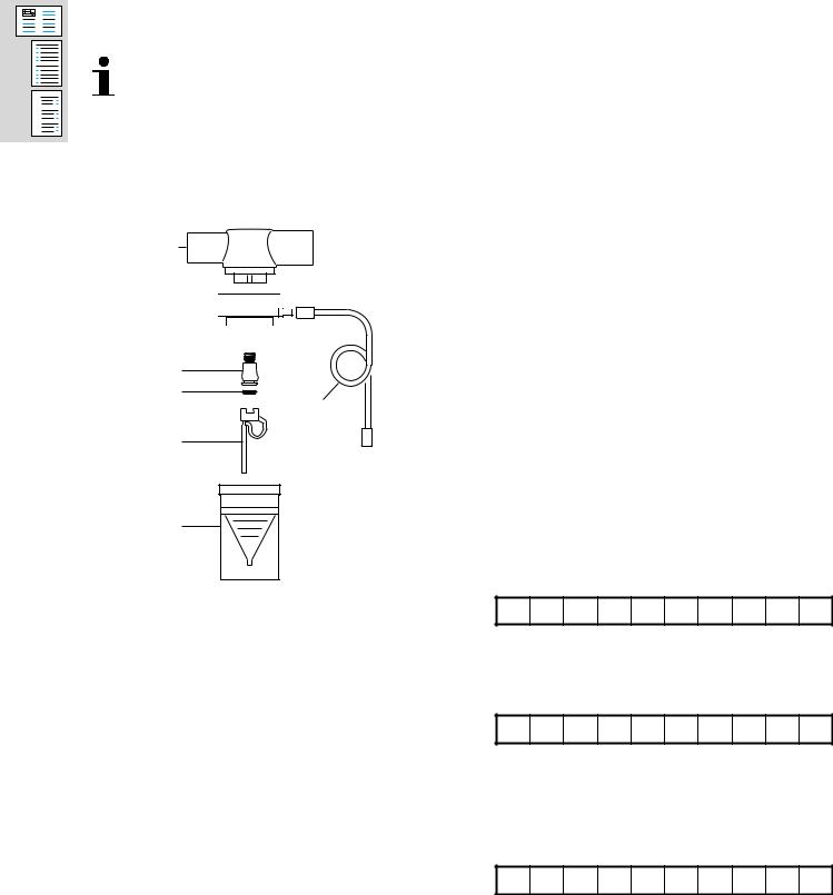
1.4.16.1Condition test
Check the condition of the following components:
1
2 


 3
3 
 4
4 
5
6
9
7
1 Patient connection
2 Nebulizer housing
3 Gasket
4 O ring
5 Nozzle
6 O ring
7 Atomizer
8 Container
9 Nebulizer hose
8
1.4.16.2Functional test
Fill nebulizer housing with water up to the "3"
mark. Supply drug nebulizer with 2.0 bar ± 0.2 bar.
Test: Vapor must be produced.
1.4.17Special accessories (if provided)
Check condition and function of the following special accessories (if available):
Resutator 2000 Child Resutator 2000
1.5Unit options and configuration
—Not applicable —
Z
F
Z F
19

A
B
C
2.Replacement of wear and tear parts
2.1 * Replace diaphragm, complete, 84 13 661, in the expiratory valve.
Next replacement:___________________
2.2Replace internal batteries (rechargeable), 18 * 41 416, (x2) every 2 years
(see also chapter "Maintenance Procedure Replacing the internal rechargeable batteries").
Next replacement:___________________
2.3Replace batteries (rechargeable), 18 43 303,
*(if fitted, x2) in Savina Mobile every 2 years. Next replacement:___________________
2.4 |
* |
Replace O2 filter, 84 08 208, and sealing |
|
|
ring, M 09 257, in valve block, complete, |
|
|
every 6 years. |
|
|
(see also chapter "Maintenance Procedure |
|
|
Replacing filter and sealing ring in O2 |
|
|
compressed gas inlet"). |
|
|
Next replacement:___________________ |
2.5 |
* |
Replace O2 pressure reducer, 84 13 666, in |
|
|
valve block, complete, every 6 years. |
|
|
(see also chapter "Maintenance Procedure |
|
|
O2 pressure reducer"). |
|
|
Next replacement:___________________ |
2.6 |
* |
Replace real-time clock, 18 45 527, on |
|
|
Control PCB, every 6 years. |
|
|
(see also chapter "Maintenance Procedure |
|
|
Replacing the real-time clock on the |
|
|
Control PCB"). |
|
|
Next replacement:___________________ |
|
|
Note: After changing the real-time clock re- |
|
|
enter the date and time. |
2.7 |
* |
Replace the blower unit with the "motor |
blower unit" spares set, 84 13 643, after 20000 hours’ operation.
(see also chapter "Maintenance Procedure Replacing the blower unit").
20
A
B
C
3.Electrical safety test
The following steps describe the safety
Seech cksdocumentaccording" Electricalto IEC 60601SafetyandTestVDEin the USA/Canada".
0751. Any decision about performing safety checks according to VDE 0751 or IEC 60601 must be made under consideration of
Recordapplicablemeasuredn tional regvalueslatioinsthe. Electricaldocument "Electrical Safety Test Form Savina". safety checks should be carried out either
according to IEC 60601 or VDE 0751.
Savina conforms to regulations of protection class I, type B; with plugged-in airway temperature sensor to regulations of protection class I, type BF.
3.1 |
Visual inspection of basic unit |
|
|
|
Check the following parts for possible |
|
|
|
damage: |
|
|
|
− |
Power cable |
|
|
− |
Power switch |
|
|
Compare the values of the power pack fuses |
|
|
|
for mains power supply and internal |
|
|
|
rechargeable battery with the rated values on |
|
|
|
the rear panel. |
Z |
|
3.2Test of electrical safety to IEC 60-601
3.2.1Protective earth conductor test
Tester |
Savina |
|
L |
|
N |
6 V |
|
|
PE |
ohm |
Test probe |
PS |
Protective earth conductor test
Connect the test probe in sequence to the following test points:
−Power pack ground stud
−Screws on housing
−Rails, at the sides of Savina (if fitted)
−Oxygen connection
Test value R≤ 0.2 ohms |
P |
21

A
B
C
3.2.2Earth leakage current test
Tester |
Savina |
L/N |
|
Mains voltage |
|
N/L |
|
PE |
|
PS |
|
Earth leakage current test |
|
Normal condition (N.C.): |
|
I ≤ 500 A |
P |
Single fault condition (S.F.C.): |
|
Neutral conductor interrupted: |
|
I ≤ 1000 A |
P |
In the following steps the test is repeated, but |
|
with the power plug turned over. This |
|
condition can be created internally with some |
|
types of test devices. |
|
Normal condition (N.C.): |
|
I ≤ 500 A |
P |
Single fault condition (S.F.C.): |
|
Neutral conductor interrupted: |
|
I ≤ 1000 A |
P |
22

A
B
C
3.2.3Patient leakage current test
Tester |
Savina |
L/N
Mains voltage
N/L
PE


 PS
PS
(1)
mA
Patient leakage current test
Connect airway temperature sensor (1) to the socket of the airway temperature sensor of Savina and to the tester.
Enter serial number of the airway temperature sensor:
P
|
Normal condition (N.C.): |
|
|
I ≤ 100 A |
P |
|
Single fault condition (S.F.C.): |
|
|
Neutral conductor interrupted: |
|
|
I ≤ 500 A |
P |
|
In the following steps the test is repeated, but |
|
|
with the power plug turned over. This |
|
|
condition can be created internally with some |
|
|
types of test devices. |
|
|
Normal condition (N.C.): |
|
|
I ≤ 100 A |
P |
|
Single fault condition (S.F.C.): |
|
|
Neutral conductor interrupted: |
|
|
I ≤ 500 A |
P |
3.2.4 |
Multiple socket outlet on trolley (if fitted) |
|
3.2.4.1Compare fuses with rated values on the
socket-outlet. |
Z |
3.2.4.2Protective earth conductor test
Check all sockets. |
|
Test value R ≤ 0.2 ohms |
P |
23

A
B
C
3.2.4.3Earth leakage current test
The test is carried out without Savina or other devices.
Normal condition (N.C.): |
|
I ≤ 50 µ A |
P |
Single fault condition (S.F.C.): |
|
Neutral conductor interrupted: |
|
I ≤ 100 µ A |
P |
In the following steps the test is repeated, but |
|
with the power plug turned over. This |
|
condition can be created internally with some |
|
types of test devices. |
|
Normal condition (N.C.): |
|
I ≤ 50 µ A |
P |
Single fault condition (S.F.C.): |
|
Neutral conductor interrupted: |
|
I ≤ 100 µ A |
P |
Continue Test Certificate at test item 4.. |
|
3.3Test of electrical safety to VDE 0751
3.3.1Protective earth conductor test
Tester |
Savina |
|
L |
|
N |
6 V |
|
|
PE |
ohm |
Test probe |
PS |
Protective earth conductor test
Connect the test probe in sequence to the following test points:
−Power pack ground stud
−Screws on housing
−Rails, at the sides of Savina (if fitted)
−Oxygen connection
Test value R ≤ 0.3 ohms |
P |
24

A
B
C
3.3.2Equivalent device leakage current test
Tester |
Savina |
Rv |
L |
Mains voltage |
N |
|
|
|
PE |
mA |
PS |
|
|
|
Test probe |
Equivalent device leakage current test
Connect airway temperature sensor (1) to the socket of the airway temperature sensor of Savina and to the tester. Connect test probe to Savina.
Enter serial number of the airway temperature sensor:
P
Subsequent measurements may exceed the first-measured value by max. 50% but must at the same time be ≤ 1000 A.
Initial value: _______ A
Note:
Always enter the initial value in a new PMS.
I ≤ 1000 A |
P |
3.3.3equivalent patient leakage current test
Tester |
Savina |
|
L |
Mains voltage |
N |
|
|
|
PE |
mA |
PS |
Test probe |
|
|
equivalent patient leakage current test
(1)
(1)
25

A
B
C
Connect airway temperature sensor (1) to the socket of the airway temperature sensor of Savina and to the tester. Connect test probe to Savina.
Enter serial number of the airway temperature sensor:
P
Subsequent measurements may exceed the first-measured value by max. 50% but must at the same time be ≤ 5000 A.
Initial value: _______ A
Note:
Always enter the initial value in a new PMS.
I ≤ 5000 A |
P |
3.3.4Multiple socket outlet on trolley (if fitted)
3.3.4.1Compare fuses with rated values on the
socket-outlet. |
Z |
3.3.4.2Protective earth conductor test Check all sockets.
Test value R ≤ 0.3 ohms |
P |
3.3.4.3Equivalent device leakage current test
The test is carried out without Savina or other devices.
Subsequent measurements may exceed the
first-measured value by max. 50% but must at the same time be ≤ 100 A.
Initial value: _______ A
Note:
Always enter the initial value in a new PMS.
I ≤ 100 A |
P |
26

A
B
C
4.Functional tests
4.1Power pack
Connect mains power and O2 supply. Switch on the unit.
4.1.1Testing the "electrical supply" display
The LEDs on the front of Savina show the following operating states:
Mains power supply: green External battery: off Internal battery:
Green: Internal rechargeable batteries are fully charged.
Yellow: Internal rechargeable batteries are |
|
being charged. |
F |
4.1.2Testing the internal supply voltage Cut mains power.
The unit continues to ventilate. Audible alarm
sounds and display message "!! Int. battery |
|
activated" appears. |
F |
The LEDs on the front of Savina show the |
|
following operating states: |
|
Mains power supply: off |
|
External battery: off |
|
Internal battery: green |
F |
4.1.3Testing the supply voltage failure alarm Connect device to the mains power supply.
Remove the fuse for the internal rechargeable battery. The fuse is located on the rear panel of the unit.
Disconnect the device from the mains power supply.
Ventilation off. All LEDs are off. Audible alarm |
|
sounds. |
F |
Switch off the unit. |
|
Restore mains power. |
|
Re-insert fuse for internal rechargeable |
|
battery. |
|
Switch unit back on. |
|
27

A
B
C
4.1.4Testing the external d.c. voltage supply
4.1.4.1Battery operation simulation
Notice: Maximum test duration = 1 minute!
“Connect Charge tester (Evita), complete" to d.c. voltage input of Savina (use the two lower sockets).
Left side terminal: |
Right side terminal: |
||
(-) black |
I |
(+) red |
|
0 |
|||
|
|
||
Using "DC voltage source, 3 -18 V" apply a voltage of 14 V to the charge tester.
After 6 seconds, at the latest, the LEDs on the |
|
front of Savina show the following operating |
|
states: |
|
Mains power supply: green |
|
External battery: green |
|
Internal battery: |
|
Green: Internal rechargeable batteries are |
|
fully charged. |
|
Yellow: Internal rechargeable batteries are |
|
being charged. |
F |
Reduce the voltage from the DC source from |
|
14 V to 11 V. |
|
The LEDs on the front of Savina show the |
|
following operating states: |
|
Mains power supply: green |
|
External battery: yellow |
|
Internal battery: |
|
Green: Internal rechargeable batteries are |
|
fully charged. |
|
Yellow: Internal rechargeable batteries are |
|
being charged. |
F |
28

A
B
C
4.1.5On-board electrical system simulation
Short-circuit the two upper sockets on the d.c. voltage input of Savina using the "Cable for charge tester".
Set the voltage from the d.c. source to 14 V and wait for the "External battery" LED to light up green.
Reduce the voltage from the DC source to 11 V.
The LEDs on the front of Savina show the following operating states:
Mains power supply: green External battery: green Internal battery:
Green: Internal rechargeable batteries are fully charged.
Yellow: Internal rechargeable batteries are |
|
being charged. |
F |
Remove the charge tester. Switch off the unit. |
|
4.2Tests in internal service mode
Switch on Savina and, at the same time, press and hold the backlighting dim-up/dim-down key and the "Config" key until the service mode is activated (see also chapter "Service Mode Entering the Internal Service Mode").
4.2.1Checking the RS232 interface Test Step 0 : call up this test step.
Connect PC to Savina using "RS232 extension" and "RS232 adapter, crossed". Start terminal program and adjust the following:
COM 1 (or corresponding) Baud rate: 19200
Data bits: 8 Parity: None Stop bits: 1 Protocol: None
The settings on the PC must match those in the Medibus log of the Savina in the "Configure" menu.
Carry out "Send Logbook" function in internal service mode.
Test value:
The content of the error log is displayed on |
|
the PC (terminal program). |
F |
29

A
B
C
4.2.2Testing the keys
Call up test steps 1 and 2 in sequence (as of SW 1.10)
Check the functioning of all keys.
Test value:
All keys should function properly. |
F |
4.2.3Nebulizer flow test
Test Step 13: call up this test step.
Connect a flowmeter tube with an oxygen scale of up to 16 L/min to the nebulizer connection. Switch on the nebulizer valve.
Test value:
Nebulizer flow = 8 L/min to 14 L/min. |
P |
4.2.4Comparing measurement functions of the flow sensors
Test Step 14: call up this test step.
Connect (short-circuit) the inspiratory and the expiratory sockets using a ventilation hose. Set the "PRESSURE BYPASS" value to
40 mbar. Test value:
The measured inspiratory and expiratory flows |
|
must not differ by more than 13%. |
P |
4.2.5Offset voltages of the airway pressure sensors
Call up test 19. Test values:
"V_PAW_INSP" = 730 mV ± 100 mV |
P |
"V_PAW_EXP" = 730 mV± 100 mV |
P |
30
A
B
C
4.2.6Testing LEDs, 7-segment displays, and LC display
Call up test step 25
Set ”Test target” value to ”LED”.
Test value: |
|
All LEDs should be evenly lit. |
F |
Set ”Test target” value to ”LCD”. |
|
Test value: |
|
The display shows no pixel errors. |
F |
Set ”Test target” value to ”7-segment”. |
|
Test value: |
|
All 7-segment displays are lit evenly. |
F |
4.2.7Plausibility test
Compare O2 supply pressure sensor with ambient pressure sensors.
Test Step 27: call up this test step.
Cut the O2 supply and relieve the pressure. Test value:
The three displayed values must not differ by |
|
more than 7%. |
P |
Switch off the unit. Cut the connection to the |
|
PC. |
|
31

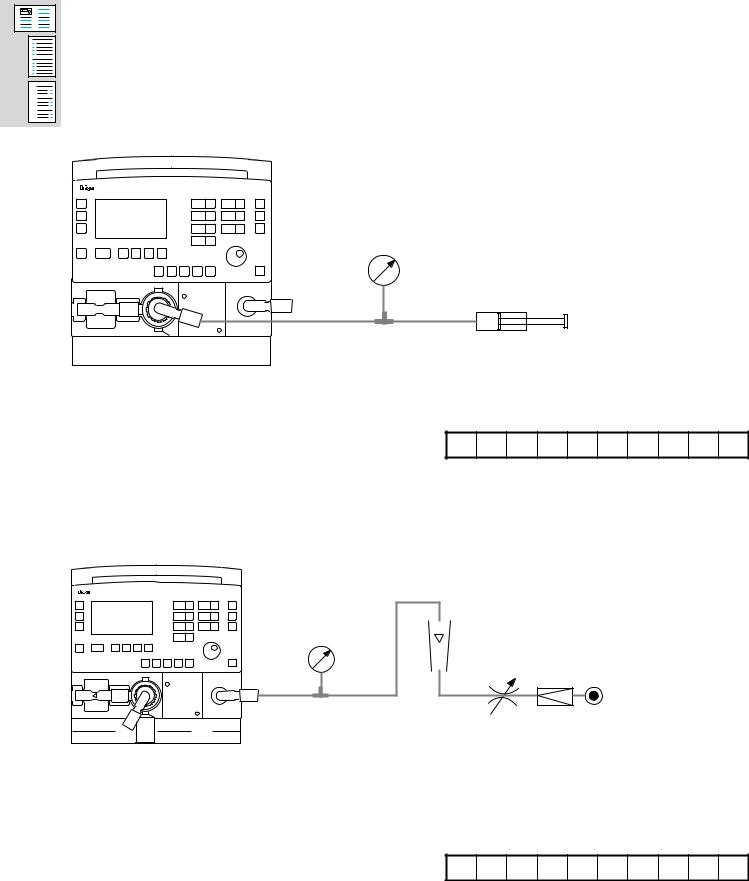
4.3Leak test, inspiration
Test set-up:
A
B
C |
Savina |
|
Pressure gauge —30 to 120 mbar
Syringe
Using the syringe build up a pressure of 40 mbar ±1 mbar at the inspiratory port.
Test value: |
|
The volume injected via the syringe in 15 |
|
seconds must be < 25 mL. |
D |
32
A
B
C
4.4Leak test, expiration
Remove the flow sensor (Spirolog sensor (A)) and sleeve (B). Seal the outlet of the
expiratory valve and use the syringe to build up a pressure of 40 mbar ± 2 mbar.
Test set-up:
Savina
Pressure gauge —30 to 120 mbar
Syringe
A  B
B
|
|
|
|
|
|
|
|
|
|
|
|
|
|
|
|
|
|
|
|
|
|
Test value: |
|
||||||
|
|
The volume injected via the syringe in 15 |
|
||||||
|
|
seconds must be < 25 mL. |
D |
||||||
4.5 |
Testing of ”120 mbar valve D1” |
|
|||||||
|
|
Test set-up: |
|
||||||
Savina
Pressure gauge
—30 to 120 mbar
Flowmeter 10 to 120 L/min
Increase the pressure until a flow rate of 120 L/min ± 5 L/min is achieved.
Test value: |
|
The pressure at the inspiratory port must be |
|
>100 mbar and <120 mbar. |
P |
33

4.6Testing "Emergency respiratory valve D2
(emergency air valve)"
Test set-up:
A
B
C
Savina
Flowmeter 10 to 120 L/min
Pressure gauge —30 to 120 mbar
Length of hoses up to Y-piece: 1.2 m each
Switch off the unit. Through the test pressure regulator with injector set a flow of
60 L/min ±3 L/min.
|
Test value: |
|
|
The pressure at the Y-piece must be between |
|
|
—3 mbar and —6 mbar. |
P |
4.7 |
O2 supply pressure monitoring |
|
|
Switch on the unit. |
|
|
Disconnect the O2 supply. |
|
|
Set the O2 concentration to 50%. |
|
|
Audible alarm sounds and display message |
|
|
"!!! No O2" appears. |
F |
Restore the O2 supply.
34

A
B
C
4.8Flush flow "expiration pressure measurement R1"
The O2 concentration of the flush flow corresponds to the set O2 concentration (select respective flowmeter tube).
Switch on the unit. Remove the expiratory valve.
Test set-up:
Savina
Flowmeter 0 to 0.2 L/min
Test value: |
|
The flush flow must be in the range |
|
> 0.02 L/min and < 0.2 L/min. |
P |
4.9Testing valves V8/V9 (emergency venting) and tightness of "Emergency respiratory valve D2"
Connect unit to test lung and adjust the following parameters:
Operating mode = IPPV, AutoFlow OFF, Pmax OFF,
Vt = 0.5 L, Tinsp = 5 s, f = 6 1/min, O2 = 21%,
PEEP= 5 mbar,
Paw high = 10 mbar above peak pressure Seal Spirolog sensor.
Test value (pressure curve shown on display):
Pressure build-up to "Paw-high limit", then |
|
drop to < 6 mbar. |
F |
4.10Testing the "Backlighting" key
Press the "Backlighting" key.
The backlighting comes on or goes off. |
F |
35

A
B
C
4.11Testing the contrast
Change the contrast in the "Config" menu.
The contrast of the display changes. |
F |
4.12Testing the micro-filter detection
Remove the micro-filter The micro-filter is located on the rear panel of Savina behind the filter cover.
Audible alarm sounds and display message |
|
"!!! No ambient air filter" appears. |
F |
Fit micro-filter and cover. |
|
4.13Testing the Spirolog sensor detection Remove the Spirolog sensor (flow sensor).
Audible alarm sounds and display message |
|
"!!! Flow Sensor?" appears. |
F |
Re-insert the Spirolog sensor. |
|
4.14Testing the temperature measurement
4.14.1Test using AWT sensor dummy
Connect the AWT sensor dummy and switch to "Test" and 34 °C.
Read out temperature value from "Values" menu of Savina.
Test value: Display = 34 °C ± 1 °C |
F |
Remove the AWT sensor dummy.
4.14.2Testing of temperature sensor (if fitted)
Connect the temperature sensor and take a reference measurement at room temperature.
Test value:
Permissible deviation between display on |
|
Savina and Thermometer: 2 °C |
F |
36

A
B
C
4.15Testing the ventilation
4.15.1Testing ventilation and O2 mixing in IPPV mode
Set the following values:
Operating mode = IPPV, AutoFlow OFF, Pmax OFF,
Vt = variable, Tinsp.= 5 s, f = 6 1/min,
O2 = 40 vol%, PEEP = 5 mbar,
Paw alarm limit = max Test set-up:
Savina
Pressure gauge —30 to 120 mbar
O2 analyzer
Test lung
37

A
B
C
Test value:
Test O2 concentration using a separate O2 analyzer, e.g. Oxydig. The value indicated by Savina must be 40 vol.% ± 1 vol.%. Read out Vte from "Values" menu of Savina.
In order to increase the O2 concentration faster, set the frequency to f = 12 1/min and Tinsp = 2 s. As soon as the O2 concentration is reached, reset values as specified previously.
Table 1: IPPV measured values
Set inspiratory Vt in mL |
Measured expiratory Vt* in mL |
O2 concentration in vol.% (Oxidig) |
||||||||||||
|
|
|
|
|
|
|
|
|
|
|
|
|
|
|
|
|
|
|
|
|
|
|
|
|
|
|
|
|
|
100 |
96 ± |
15 |
|
|
|
|
40 ± 2 |
|
|
|
|
|
|
|
|
|
|
|
|
|
|
|
|
|
|
|
|
|
|
200 |
192 ± 26 |
|
|
|
|
40 ± 2 |
|
|
|
|
|
|
||
|
|
|
|
|
|
|
|
|
|
|
|
|
|
|
1000 |
960 ± 130 |
|
|
|
|
40 ± 2 |
|
|
|
|
|
|
||
|
|
|
|
|
|
|
|
|
|
|
|
|
|
|
*The measured expiratory Vt refers to the |
|
|
|
|
|
|
|
|
|
|
|
|
||
patient’s lung conditions (BTPS). |
P |
|
|
|
|
|
|
|
|
|
|
|
|
|
|
|
|
|
|
|
|
|
|
|
|
|
|
|
|
4.15.2Testing of pressure-controlled ventilation
Units with BIPAP option: continue with test step 4.15.2.1. All other units: continue with test step 4.15.2.2.
4.15.2.1Testing the pressure controlled ventilation in BIPAP mode
Set the following values: BIPAP,
f = 6 1/min, Paw = max, PEEP = variable, Pinsp = variable, PASB = 0 mbar, O2 = 80 vol.%, Tinsp.= 5 s,
FlowAcc = 60 mbar/s Test set-up:
As in test step 4.15.1.
38

A
B
C
Test value:
Test O2 concentration using a separate O2 analyzer, e.g. Oxydig. The value indicated by Savina must be 80 vol.% ± 1 vol.%.
In order to increase the O2 concentration faster, set the frequency to f = 12 1/min and Tinsp = 2 s. As soon as the O2 concentration is reached, reset values as specified previously.
Table 2: BIPAP measured values
PEEP setpoint in |
Set Pinsp in mbar |
Actual PEEP in |
Actual Pinsp in |
O2 concentration in vol.% (Oxidig) |
|
mbar |
mbar |
mbar |
|||
|
|
||||
|
|
|
|
|
|
|
|
|
|
|
|
5 |
25 |
5 ± 2 |
25 ± 2 |
80 ± 3 |
|
|
|
|
|
|
|
20 |
60 |
20 ± 2 |
60 ± 2 |
80 ± 3 |
|
|
|
|
|
|
|
5 |
25 |
5 ± 2 |
25 ± 2 |
80 ± 3 |
|
|
|
|
|
|
P
Continue with test step 4.15.3.
4.15.2.2Testing the pressure controlled ventilation in CPAP mode
Set the following values: CPAP,
Apnea ventilation ON, fApnea = 10 1/min, VtApnea = 2000 mL, Paw = variable, PEEP = variable,
O2 = 80 vol.%, FlowAcc = 60 mbar/s
Test set-up:
As in test step 4.15.1.
39

A
B
C
Test value:
Test O2 concentration using a separate O2 analyzer, e.g. Oxydig. The value indicated by Savina must be 80 vol.% ±1 vol.%.
Table 3: CPAP measured values
PEEP setpoint in |
Pmax setpoint in |
|
Actual PEEP in |
Actual Pmax in |
O2 concentration in vol.% (Oxidig) |
|||||||||||
mbar |
|
mbar |
|
mbar |
|
|
mbar |
|||||||||
|
|
|
|
|
|
|
|
|
|
|
||||||
|
|
|
|
|
|
|
|
|
|
|
|
|
|
|
|
|
|
|
|
|
|
|
|
|
|
|
|
|
|
|
|
|
|
5 |
|
30 |
|
5 ± 2 |
|
25 ± 2 |
|
|
80 ± 3 |
|
|
|
|
|
||
|
|
|
|
|
|
|
|
|
|
|
|
|
|
|
|
|
20 |
|
55 |
|
20 ± 2 |
|
50 ± 2 |
|
|
80 ± 3 |
|
|
|
|
|
||
|
|
|
|
|
|
|
|
|
|
|
|
|
|
|
|
|
5 |
|
30 |
|
5 ± 2 |
|
25 ± 2 |
|
|
80 ± 3 |
|
|
|
|
|
||
|
|
|
|
|
|
|
|
|
|
|
|
|
|
|
|
|
|
|
|
|
|
P |
|
|
|
|
|
|
|
|
|
|
|
|
|
|
|
|
|
|
|
|
|
|
|
|
|
|
|
|
4.15.3 |
Testing trigger characteristics in CPAP/ASB |
|
|
|
|
|
|
|
|
|
|
|
|
|||
|
|
|
|
|
|
|
|
|
|
|
|
|||||
|
mode |
|
|
|
|
|
|
|
|
|
|
|
|
|
|
|
|
Set the following values: |
|
|
|
|
|
|
|
|
|
|
|
|
|
||
|
CPAP/ASB, |
|
|
|
|
|
|
|
|
|
|
|
|
|
||
|
Paw alarm limit high = 30 mbar, |
|
|
|
|
|
|
|
|
|
|
|
|
|
||
|
PEEP = 5 mbar, |
|
|
|
|
|
|
|
|
|
|
|
|
|
||
|
O2 = 40 vol%, |
|
|
|
|
|
|
|
|
|
|
|
|
|
||
|
ASB = 20 mbar, |
|
|
|
|
|
|
|
|
|
|
|
|
|
||
|
Trigger = 3 L/min |
|
|
|
|
|
|
|
|
|
|
|
|
|
||
|
Test set-up: |
|
|
|
|
|
|
|
|
|
|
|
|
|
||
|
As in test step 4.15.1. |
|
|
|
|
|
|
|
|
|
|
|
|
|
||
|
Test value: |
|
|
|
|
|
|
|
|
|
|
|
|
|
||
|
Unit does not trigger an ASB breath. |
F |
|
|
|
|
|
|
|
|
|
|
|
|||
|
|
|
|
|
|
|
|
|
|
|
|
|||||
|
Simulate breathing. |
|
|
|
|
|
|
|
|
|
|
|
|
|
||
|
|
|
|
|
|
|
|
|
|
|
|
|
|
|||
|
Test value: |
|
|
|
|
|
|
|
|
|
|
|
|
|
||
|
Trigger LED must light up and ASB breath |
|
|
|
|
|
|
|
|
|
|
|
|
|||
|
must be triggered. ASB pressure 25 mbar ±3 |
|
|
|
|
|
|
|
|
|
|
|
|
|||
|
mbar. |
|
|
|
P |
|
|
|
|
|
|
|
|
|
|
|
|
|
|
|
|
|
|
|
|
|
|
|
|
|
|
|
|
40
A
B
C
4.16Testing the optional central alarm (if available) Activate alarm, e.g. by pulling power plug. Test set-up:
 Central alarm socket (located on the rear panel of the unit)
Ohmmeter
Test value: |
|
Contacts "3" and "5" close if an alarm occurs. |
|
Contacts "1" and "3" open. |
F |
4.17Service hours counter and log entries Switch off Savina.
Switch on Savina and, at the same time, press and hold the backlighting dim-up/dim-down key and the "Config" key until the service mode is activated (see also chapter "Service Mode Entering the Internal Service Mode").
Call up test 0:
Perform "DELETE LOGBOOK" function. Call up test 3:
Perform "RESET SERVICE HOURS" function.
5.Place fully functional unit at user’s/owner’s disposal.
6.Confirmation of test Name:
Date:
Signature:
* These steps are regarded as repair work and are therefore not included in the inspection
service price.
41

A
B
C
7.Report:
__________________________________________________________________________________________
__________________________________________________________________________________________
__________________________________________________________________________________________
__________________________________________________________________________________________
__________________________________________________________________________________________
__________________________________________________________________________________________
__________________________________________________________________________________________
__________________________________________________________________________________________
__________________________________________________________________________________________
__________________________________________________________________________________________
__________________________________________________________________________________________
__________________________________________________________________________________________
__________________________________________________________________________________________
__________________________________________________________________________________________
__________________________________________________________________________________________
__________________________________________________________________________________________
__________________________________________________________________________________________
__________________________________________________________________________________________
__________________________________________________________________________________________
__________________________________________________________________________________________
__________________________________________________________________________________________
__________________________________________________________________________________________
42

A
B
C
8.Annex
8.1List of service equipment for Test Certificate
Table 4: Test Equipment
Designation |
Order number |
|
|
|
|
Test lung |
84 03 201 |
|
|
Patient adapter for Paw measurement |
8290285 |
|
|
Oxydig |
8304411 |
|
|
Pressure gauge, digital 100 mbar |
79 10 722 |
|
|
VDE tester |
79 10 594 |
|
|
RS232 adapter, crossed |
79 01 888 |
|
|
RS232 extension |
79 01 808 |
|
|
Test pressure regulator |
79 011 482 |
|
|
Injector |
2M 06 912 |
|
|
Syringe, 50 mL |
79 01 541 |
|
|
Flowmeter block |
79 01 161 |
|
|
Flowmeter, 10 -120 L/min |
79 00 718 |
|
|
AWT sensor dummy |
79 00 405 |
|
|
Charge tester (Evita), complete |
79 10 385 |
|
|
Cable for charge tester |
79 10 387 |
|
|
Multimeter |
79 01 021 |
|
|
DC voltage source, 3 -18 V |
79 10 426 |
|
|
Thermometer |
2M 11 111 |
|
|
For testing castors on trolley: |
|
|
|
Torque spanner |
79 00 909 |
|
|
Special open-ended wrench, 17 mm |
79 01 204 |
|
|
Special open-ended wrench, 41 mm |
79 10 462 |
|
|
43

|
|
|
|
|
|
|
|
|
|
|
|
|
|
|
|
|
|
|
|
|
|
|
|
|
|
|
|
|
C |
|
B |
|
A |
|
|
|
|
|
|
|
|
|
|
|
|
|
|
|
|
|
|
||||
|
|
|
|
|
|
|
|
|
|
|
|
|
|
|
|
|
|
|
|
|
|
|
|
|
|
|
|
|
|
|
|
|
|
|
|
|
|
|
|
|
|
|
|
|
|
|
|
|
|
|
|
|
|
|
|
S3.2 |
drawer unit |
inspiration block |
|
E |
|||
|
|
||
O2 |
|
|
mixing chamber
F1 |
|
SD1 |
|
AIR |
|
|
|
F5 |
D6 |
|
|
O2 |
|
||
|
|
||
oxygen |
|
P |
|
concentrator |
|
||
|
E |
||
|
|
||
|
|
S6 |
|
R5.1-R5.8 |
|
|
|
V7.1-V7.8 |
|
|
|
|
P |
S5 |
|
|
V4 |
||
|
E |
||
F2 DR1 |
|
||
|
NC C R3 |
||
O2 |
|
||
R2 |
NO |
||
compressed gas |
|||
|
|
||
|
|
V5 |
|
S7 |
|
|
R6
O2
E
S3.1
V1 |
D1 |
|
D2 |
||
|
humidifier
SD2 |
F4 |
S1 |
D4 |
|
|
|
|
|
V |
|
|
|
|
cooler |
|
|
NO |
V8 |
NO |
V6.1 |
|
V9 |
C |
|
NC |
||
|
|
NC |
|
|
||
|
|
|
|
C |
|
|
blower |
|
|
|
|
|
|
|
|
|
|
|
|
|
|
|
|
|
|
P |
E |
|
|
V6.3 |
|
|
|
|
pressure |
|
|
|
S4.1 |
||
|
|
|
|
|||
|
|
|
|
S4.2 |
||
measuring block |
|
|
|
|
E |
|
P
P
E |
C V6.2 |
S4.3 |
NC |
NO
D5 |
flush flow |
|
|
|
R1 |
 V3
V3
S2
V
D3
P |
R4 |
patient system |
nebulizer |
|
E |
|
valve block (flow-control block)
2.8
diagram Pneumatic
44

50
red Si-2x1 Hose
natural Si-5.2x1 Hose
natural Si-12x3 Hose
|
|
|
|
|
|
|
|
C |
B |
A |
|
|
|
|
|
135 |
|
|
|
|
3.8 |
|
|
|
|
|
|
|
|
|
|
|
|
|
|
R3 |
140 |
|
|
150 |
|
Tubing |
|
|
|
|
|
|
|
|
|
|||
|
|
|
|
|
|
1 2 3 |
|
|
|
|
|
|
|
|
|
|
|
|
|
|
|
|
|
|
|
|
|
4 |
|
|
|
diagram |
|
|
Pressure regulator |
|
|
|
Neb. |
|
|
|
|
|
|
|
|
|
. |
|
|
|
|
|
|
|
|
|
|
|
5 |
O2 valve block |
|
|
|
|
|
|
|
|
|
|
|
|
||
|
|
Volume |
|
|
|
|
|
|
|
|
|
|
70 |
220 |
|
|
|
|
|
20 |
|
|
|
|
|
|
|
|
R1 |
|
|
|
|
600 |
|
|
|
|
|
110 |
|
|
|
|
|
|
|
Pressure measuring block |
|
|
|
|||
|
|
50 |
100 |
|
|
|
|
|
|
|
|
|
|
|
|
|
|
|
|
|
|
Return line/ |
|
|
|
|
.Insp |
.Exp |
220 |
|
|
|
pressure source |
|
|
|
|
|
|
||||
|
|
|
|
|
|
|
|
|
||
R6 |
|
120 |
|
* |
|
|
|
|
|
|
480 |
|
|
|
|
|
|
|
|
||
|
|
O2-2 O2-1 |
|
|
|
|
|
|
|
|
|
Exp. block |
O2 sensor |
|
|
|
|
120 |
|
|
|
|
mount |
|
|
|
|
|
|
|
||
|
|
|
|
|
|
|
|
|
||
|
|
|
|
|
|
|
|
|
|
|
|
|
|
|
|
|
|
|
230 |
|
|
brownSi-2x1Hose blueSi-2x1Hose |
|
TSI hose |
|
|
|
|
*Only available in the |
|||
|
|
|
20 |
Insp. block |
first batch of units |
|||||
|
|
|
|
|||||||
45

A
B
C
R5664900T01.fm 27.08.01 |
For internal use only. Copyright reserved. |
|
|
|
6HUYLFH 6WUDWHJ\ |
,WHPV WR EH UHSDLUHG 5HSDLU ORFDWLRQV |
|
|
|
6HUYLFH 6WUDWHJ\
,WHPV WR EH UHSDLUHG 5HSDLU ORFDWLRQV
What |
Test instructions/test aids |
Repair |
|
|
|
|
|
|
|
|
|
Inspection |
Test Certificate, service |
Minor repairs, battery |
|
|
documentation |
replacement etc. |
|
|
|
|
|
On-site repair |
Test Certificate, service |
Minor repairs, e.g. changing a |
|
|
documentation |
fuse, exchanging a module, |
|
|
|
calibration |
|
|
|
|
|
Workshop repair |
Test Certificate, service |
Minor repairs, e.g. changing a |
|
|
documentation |
fuse, exchanging a module, |
|
|
|
calibration |
|
|
|
|
|
Repair in Lübeck |
Test Certificate, service |
Repair at component level |
|
|
documentation, design |
|
|
|
documentation |
|
|
|
|
|
|
Dräger Medizintechnik GmbH |
Service Strategy Savina Version 2.0 |
Page 46 |
A
B
C
|
|
|
6HUYLFH 6WUDWHJ\ |
*HQHUDO QRWHV |
|
|
|
*HQHUDO QRWHV
(OHFWURVWDWLF GLVFKDUJH PD\ GDPDJH WKH HOHFWURQLF FRPSRQHQWV :KHQ KDQGOLQJ HOHFWURVWDWLF VHQVLWLYH GHYLFHV XVH VWDWLF GLVVLSDWLYH PDW DQG D ZULVW VWUDS
The O2 sensors and batteries are special waste items. Dispose of the O2 sensors and batteries in accordance with local waste disposal regulations.
R5664900T01.fm 27.08.01 |
For internal use only. Copyright reserved. |
Dräger Medizintechnik GmbH |
Service Strategy Savina Version 2.0 |
Page 47

A
B
C
R5664900T02.fm 27.08.01 |
For internal use only. Copyright reserved. |
0DLQWHQDQFH 3URFHGXUH
0DLQWHQDQFH 3URFHGXUH
The maintenance procedure described here corresponds to the maintenance procedure set out in the Test Certificate. For the maintenance intervals refer to the Test Certificate: "Replacement of wear and tear parts". The following maintenance procedure is described:
−Replacing filter and sealing ring in O2 compressed gas inlet
−Replacing the O2 pressure reducer
−Replacing the blower unit
−Replacing the internal rechargeable batteries
−Replacing the real-time clock on the Control PCB
O2 sensors, microbial filter, diaphragm in expiratory valve and dust filter see "Instructions for Use/Operating Instructions".
Dräger Medizintechnik GmbH |
Maintenance Procedure Savina Version 2.0 |
Page 48 |

A
B
C
R5664900T02.fm 27.08.01 |
For internal use only. Copyright reserved. |
0DLQWHQDQFH 3URFHGXUH 5HSODFLQJ ILOWHU DQG VHDOLQJ ULQJ LQ 22 FRPSUHVVHG JDV LQOHW
5HSODFLQJ ILOWHU DQG VHDOLQJ ULQJ LQ 22 FRPSUHVVHG JDV LQOHW
•Switch off the unit.
•Disconnect the O2 compressed gas supply.
•Open the unit (see "Removing the rear panel").
•Remove the micro-filter .
•Remove the drawer unit .
1
2
)LJ Removing the micro-filter.
Dräger Medizintechnik GmbH |
Maintenance Procedure Savina Version 2.0 |
Page 49 |

0DLQWHQDQFH 3URFHGXUH 5HSODFLQJ ILOWHU DQG VHDOLQJ ULQJ LQ 22 FRPSUHVVHG JDV LQOHW
• Remove the screws .
A
B
C
3 |
|
|
|
3 |
|||
|
)LJ Removal of valve block 1
R5664900T02.fm 27.08.01 |
For internal use only. Copyright reserved. |
Dräger Medizintechnik GmbH |
Maintenance Procedure Savina Version 2.0 |
Page 50
A
B
C
0DLQWHQDQFH 3URFHGXUH 5HSODFLQJ ILOWHU DQG VHDOLQJ ULQJ LQ 22 FRPSUHVVHG JDV LQOHW
Remove also the sealing ring from the NIST connector. Otherwise the sealing ring could be lost during further disassembly.
• Remove NIST connector (if fitted) and sealing ring.
R5664900T02.fm 27.08.01 |
For internal use only. Copyright reserved. |
)LJ NIST connector
Dräger Medizintechnik GmbH |
Maintenance Procedure Savina Version 2.0 |
Page 51

A
B
C
0DLQWHQDQFH 3URFHGXUH 5HSODFLQJ ILOWHU DQG VHDOLQJ ULQJ LQ 22 FRPSUHVVHG JDV LQOHW
• Remove inspiratory flow sensor from plug-in unit and push up.
 Plug-in unit
 Inspiratory flow sensor
)LJ Removing the inspiratory flow sensor
R5664900T02.fm 27.08.01 |
For internal use only. Copyright reserved. |
•Remove large, transparent hose (which connects valve block to plug-in unit) from the plug-in unit.
Dräger Medizintechnik GmbH |
Maintenance Procedure Savina Version 2.0 |
Page 52 |

A
B
C
R5664900T02.fm 27.08.01 |
For internal use only. Copyright reserved. |
0DLQWHQDQFH 3URFHGXUH 5HSODFLQJ ILOWHU DQG VHDOLQJ ULQJ LQ 22 FRPSUHVVHG JDV LQOHW
• Pull out the valve block a little and turn 90° counter-clockwise.
)LJ Turning the valve block
• Mark the hoses leading to the valve block.
Before removing the hoses from the valve block, mark them and make a note of their fitting positions.
• Remove the hoses.
Dräger Medizintechnik GmbH |
Maintenance Procedure Savina Version 2.0 |
Page 53 |

A
B
C
0DLQWHQDQFH 3URFHGXUH 5HSODFLQJ ILOWHU DQG VHDOLQJ ULQJ LQ 22 FRPSUHVVHG JDV LQOHW
• Remove the connector of the O2 Valve PCB.
O2 Valve
PCB
)LJ Removal of valve block 2
• Remove the valve block.
R5664900T02.fm 27.08.01 |
For internal use only. Copyright reserved. |
Dräger Medizintechnik GmbH |
Maintenance Procedure Savina Version 2.0 |
Page 54

A
B
C
R5664900T02.fm 27.08.01 |
For internal use only. Copyright reserved. |
0DLQWHQDQFH 3URFHGXUH 5HSODFLQJ ILOWHU DQG VHDOLQJ ULQJ LQ 22 FRPSUHVVHG JDV LQOHW
• Remove the screws .
|
|
4 |
|
4 |
|||
|
|
)LJ Removing the filter
• Remove the socket.
Before removing the filter and sealing ring, make a note of the fitting position.
• Remove the filter and sealing ring.
Dräger Medizintechnik GmbH |
Maintenance Procedure Savina Version 2.0 |
Page 55 |

A
B
C
0DLQWHQDQFH 3URFHGXUH 5HSODFLQJ ILOWHU DQG VHDOLQJ ULQJ LQ 22 FRPSUHVVHG JDV LQOHW
• Insert the new filter and sealing ring.
If the O2 pressure reducer needs to be replaced as well, proceed with "Replacing the O2 pressure reducer".
• Assemble the unit.
Make sure not to kink any hoses during assembly.
• Perform the safety check and functional check as per the Test Certificate.
R5664900T02.fm 27.08.01 |
For internal use only. Copyright reserved. |
Dräger Medizintechnik GmbH |
Maintenance Procedure Savina Version 2.0 |
Page 56

A
B
C
|
|
|
0DLQWHQDQFH 3URFHGXUH |
22 SUHVVXUH UHGXFHU |
|
|
22 SUHVVXUH UHGXFHU
5HSODFLQJ WKH 2 SUHVVXUH UHGXFHU
•Remove the valve block (see "Replacing filter and sealing ring in O2 compressed gas inlet"). Follow the instructions given there from "Switch off the unit." to "Remove the valve block.").
Before removing the O2 pressure reducer from the valve block, make a note of its fitting position and, after removing it, the connector layout (see underside of pressure reducer).
R5664900T02.fm 27.08.01 |
For internal use only. Copyright reserved. |
Dräger Medizintechnik GmbH |
Maintenance Procedure Savina Version 2.0 |
Page 57

|
|
|
0DLQWHQDQFH 3URFHGXUH |
22 SUHVVXUH UHGXFHU |
|
|
• Remove the screws .
A
B
C
1
R5664900T02.fm 27.08.01 |
For internal use only. Copyright reserved. |
)LJ Replacing the O2 pressure reducer
•Make a note of the fitting position.
•Remove the O2 pressure reducer.
•Make a note of the connector layout.
•Fit the new O2 pressure reducer and O-rings.
•Continue with "Adjusting the O2 pressure reducer".
Dräger Medizintechnik GmbH |
Maintenance Procedure Savina Version 2.0 |
Page 58

A
B
C
|
|
|
0DLQWHQDQFH 3URFHGXUH |
22 SUHVVXUH UHGXFHU |
|
|
$GMXVWLQJ WKH 2 SUHVVXUH UHGXFHU
To adjust the pressure reducer the valve block must be removed (see "Replacing filter and sealing ring in O2 compressed gas inlet". Follow the instructions given there from "Switch off the unit." to "Remove the valve block.").
• Connect the O2 Valve PCB to the Savina.
•Connect the O2 pressure supply.
•Connect pressure gauge, 0 to 6 bar (Use valid test equipment. The illustration shows only a schematic) to the nebulizer outlet of the valve block.
R5664900T02.fm 27.08.01 |
For internal use only. Copyright reserved. |
O2 Valve PCB connector
 O2 pressure supply
Nebulizer outlet
)LJ Pressure reducer test set-up
Dräger Medizintechnik GmbH |
Maintenance Procedure Savina Version 2.0 |
Page 59

A
B
C
R5664900T02.fm 27.08.01 |
For internal use only. Copyright reserved. |
|
|
|
0DLQWHQDQFH 3URFHGXUH |
22 SUHVVXUH UHGXFHU |
|
|
•Switch on Savina and start service mode (see service mode, chapter "Entering the Internal Service Mode").
•Select Test Step 13.
•Switch on the nebulizer valve.
To adjust the pressure reducer the control knob must be raised. After making the adjustment the control knob must be pushed down again and secured with stop varnish.
•Raise the pressure reducer control knob.
•Adjust the pressure on the pressure gauge with the pressure reducer to 2 bar ± 0.2 mbar.
•Push the pressure reducer control knob back down.
•Secure the control knob with stop varnish.
•Switch off Savina.
•Assemble the unit.
•Perform the safety check and functional check as per the Test Certificate.
Dräger Medizintechnik GmbH |
Maintenance Procedure Savina Version 2.0 |
Page 60 |
A
B
C
R5664900T02.fm 27.08.01 |
For internal use only. Copyright reserved. |
|
|
|
0DLQWHQDQFH 3URFHGXUH |
5HSODFLQJ WKH EORZHU XQLW |
|
|
|
5HSODFLQJ WKH EORZHU XQLW
•Open the unit fully (see "Opening the unit").
•Remove the connector for the return valve (X644) from the Control PCB (see "View, Control PCB").
•Fold away the backing plate on which the Control PCB is mounted (see "Folding away the Control PCB").
•Remove the connector from the Motor Commutator PCB.
1
Motor Commutator PCB
)LJ Motor Commutator PCB connector
Dräger Medizintechnik GmbH |
Maintenance Procedure Savina Version 2.0 |
Page 61 |

|
|
|
0DLQWHQDQFH 3URFHGXUH |
5HSODFLQJ WKH EORZHU XQLW |
|
|
|
• Remove the screws from the fan.
A
B
C
 2
2
R5664900T02.fm 27.08.01 |
For internal use only. Copyright reserved. |
)LJ Removing the fan.
• Place the fan on the plate of the Control PCB.
Dräger Medizintechnik GmbH |
Maintenance Procedure Savina Version 2.0 |
Page 62

0DLQWHQDQFH 3URFHGXUH
• Remove the micro-filter .
• Remove the drawer unit .
A
B
C
3
4 

)LJ Removing the micro-filter.
R5664900T02.fm27.08.01 |
Forinternal use only. Copyright reserved. |
Maintenance Procedure Savina Version 2.0 |
|
Dräger Medizintechnik GmbH |
5HSODFLQJ WKH EORZHU XQLW
Page 63

A
B
C
R5664900T02.fm 27.08.01 |
For internal use only. Copyright reserved. |
|
|
|
0DLQWHQDQFH 3URFHGXUH |
5HSODFLQJ WKH EORZHU XQLW |
|
|
|
• Remove inspiratory flow sensor from plug-in unit.
 Plug-in unit
 Inspiratory flow sensor
)LJ Removing the inspiratory flow sensor
• Remove the fixing screws of the blower bracket.
 5
5
)LJ Slacken the blower bracket.
Dräger Medizintechnik GmbH |
Maintenance Procedure Savina Version 2.0 |
Page 64 |

A
B
C
R5664900T02.fm 27.08.01 |
For internal use only. Copyright reserved. |
|
|
|
0DLQWHQDQFH 3URFHGXUH |
5HSODFLQJ WKH EORZHU XQLW |
|
|
|
When withdrawing the blower pay attention to the cable connections. The cable connections must also be fed out. The removed cables are those of the Control PCB and the Motor Commutator PCB.
•Push the side panel away slightly and carefully withdraw the blower out of the unit towards the rear.
•Remove the fixing screws (screws are tighten to 1.2 Nm ± 0.3 Nm).
|
|
|
|
|
|
|
|
|
|
|
|
6 |
|
|
|
6 |
|
|
|
|
|
|
|
|
|
|
|
||
|
|
|
|
|
|
|
|
|
|
|
|
|
|
|
|
|
|
|
|
|
|
|
|
|
|
|
|
|
|
|
|
|
|
6 |
|
|
|
|
|
|
|
|
||
|
|
|
|
|
|
|
|
|
|
|
|
|||
|
6 |
|
|
|
|
|
|
|
|
|
6 |
|||
|
|
|
|
|
|
|
|
|
|
|
|
|
|
|
|
|
|
|
6 |
6 |
|
|
|
|
|
|
|
|
6
)LJ Removing the blower unit.
• Remove the blower block.
Dräger Medizintechnik GmbH |
Maintenance Procedure Savina Version 2.0 |
Page 65 |

A
B
C
R5664900T02.fm 27.08.01 |
For internal use only. Copyright reserved. |
|
|
|
0DLQWHQDQFH 3URFHGXUH |
5HSODFLQJ WKH EORZHU XQLW |
|
|
|
• Remove the fixing screws .
7 |
|
|
|
|
|
|
|
|
|
|
|
|
7 |
||
|
|
||||||
|
|
||||||
|
|
|
|
|
|
|
|
|
|
|
|
|
7 |
|
7 |
|
|
||||
|
|
|
|
|
|
|
)LJ Removing the blower.
•Remove the blower.
•Install the new blower and seals.
The screws in step "Remove the fixing screws 6 (screws are tighten to
1.2Nm ±0.3 Nm)." are tightened with to a specific torque.
•Assemble the unit.
•Perform the safety check and functional check as per the Test Certificate.
Dräger Medizintechnik GmbH |
Maintenance Procedure Savina Version 2.0 |
Page 66 |

A
B
C
|
|
|
0DLQWHQDQFH 3URFHGXUH |
5HSODFLQJ WKH LQWHUQDO UHFKDUJHDEOH EDWWHULHV |
|
|
|
5HSODFLQJ WKH LQWHUQDO UHFKDUJHDEOH EDWWHULHV
•Open the unit (see "Removing the rear panel").
•Remove the fuse for the rechargeable batteries by levering it out carefully with a screwdriver.
R5664900T02.fm 27.08.01 |
For internal use only. Copyright reserved. |
)LJ Removing the fuse of the rechargeable batteries.
Dräger Medizintechnik GmbH |
Maintenance Procedure Savina Version 2.0 |
Page 67

A
B
C
R5664900T02.fm 27.08.01 |
For internal use only. Copyright reserved. |
|
|
|
0DLQWHQDQFH 3URFHGXUH |
5HSODFLQJ WKH LQWHUQDO UHFKDUJHDEOH EDWWHULHV |
|
|
|
• Remove the screws and the cover .
|
|
|
|
|
|
|
1 |
|
1 |
|
|||||||
|
|
|
||||||
|
|
|
|
|
|
|
|
|
|
|
|
2 |
|
|
|
|
|
|
|
|
|
|
|
|
||
|
1 |
1 |
|
|||||
)LJ Removing the rechargeable batteries, part 1
7KH UHFKDUJHDEOH EDWWHULHV DUH VSHFLDO ZDVWH LWHPV 'LVSRVH RI WKH UHFKDUJHDEOH EDWWHULHV LQ DFFRUGDQFH ZLWK ORFDO ZDVWH GLVSRVDO UHJXODWLRQV
5HYHUVLQJ WKH SRODULW\ RI WKH UHFKDUJHDEOH EDWWHULHV ZLOO GDPDJH WKH EDWWHULHV DQG WKH SRZHU SDFN 0DNH D QRWH RI WKH FRQQHFWRU OD\RXW DQG HQVXUH FRUUHFW SRODULW\ ZKHQ ILWWLQJ WKH UHFKDUJHDEOH EDWWHULHV
Dräger Medizintechnik GmbH |
Maintenance Procedure Savina Version 2.0 |
Page 68 |
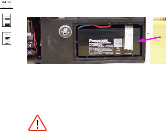
|
|
|
0DLQWHQDQFH 3URFHGXUH |
5HSODFLQJ WKH LQWHUQDO UHFKDUJHDEOH EDWWHULHV |
|
|
|
• Remove the rechargeable batteries.
A
B
C
R5664900T02.fm 27.08.01 |
For internal use only. Copyright reserved. |
)LJ Removing the rechargeable batteries, part 2
• Fit new rechargeable batteries.
,QDGHTXDWH YROWDJH 7KH QHZ UHFKDUJHDEOH EDWWHULHV DUH QRW VXIILFLHQWO\ FKDUJHG &RQQHFW WKH 6DYLQD IRU DW OHDVW KRXUV WR WKH PDLQV VXSSO\ 6DYLQD GRHV QRW QHHG WR EH VZLWFKHG RQ
•Assemble the unit.
•Perform the safety check and functional check as per the Test Certificate.
Dräger Medizintechnik GmbH |
Maintenance Procedure Savina Version 2.0 |
Page 69 |

A
B
C
R5664900T02.fm 27.08.01 |
For internal use only. Copyright reserved. |
|
|
|
0DLQWHQDQFH 3URFHGXUH |
5HSODFLQJ WKH UHDO WLPH FORFN RQ WKH &RQWURO 3&% |
|
|
|
5HSODFLQJ WKH UHDO WLPH FORFN RQ WKH &RQWURO 3&%
Read the following information before replacing the real-time clock (RTC):
'R QRW UHSODFH WKH ((3520 DQG WKH 57& RQ WKH &RQWURO 3&% DW WKH VDPH WLPH 2WKHUZLVH WKH UHFRUGHG RSHUDWLQJ KRXUV ZLOO EH ORVW ,I \RX QHHG WR UHSODFH ERWK FRPSRQHQWV GR LW LQ VHTXHQFH WKDW LV FRPSOHWH WKH UHSODFHPHQW RI RQH FRPSRQHQW ILUVW EHIRUH VWDUWLQJ WKH QH[W RQH
5HSODFH WKH 57& RQO\ ZLWK D EUDQG QHZ 57& WKDW KDV QRW EHHQ LQ XVH EHIRUH
7KH XQLW PXVW EH RII ZKHQ UHSODFLQJ WKH 57&
(QVXUH WKH FRUUHFW SRODULW\ ,I WKH SRODULW\ RI WKH 57& LV UHYHUVHG WKH 57& ZLOO EH GHVWUR\HG 5HPHPEHU WKH LQVWDOODWLRQ SRVLWLRQ RI WKH 57&
7KH 57& KDV D EDWWHU\ 'LVSRVH RI WKH ROG 57& DFFRUGLQJ WR ORFDO ZDVWH GLVSRVDO UHJXODWLRQV
The RTC keeps information about operating hours and settings, e.g. alarms and configurations. This information must be read out and written down before replacing the RTC.
Dräger Medizintechnik GmbH |
Maintenance Procedure Savina Version 2.0 |
Page 70 |
A
B
C
R5664900T02.fm 27.08.01 |
For internal use only. Copyright reserved. |
0DLQWHQDQFH 3URFHGXUH |
5HSODFLQJ WKH UHDO WLPH FORFN RQ WKH &RQWURO 3&% |
•Read out and write down operating hours and settings, e.g. alarms and configurations.
•Switch off the unit.
•Open the unit (see "Opening the operator control panel").
•Remove the RTC (D19) from the Control PCB.
X403Emergency air valve X700Control pressure sensor X701Calibration valve, control sensor |
Operator |
control |
panel |
X8 |
X71 |
interf |
|
Powerswitch |
|
|
|
|
|
X71 |
232RS |
X2 |
X2X20 PiezopackPower charging management |
||
|
D19 |
|
|
|
X8 |
|
|
X12 |
X12 |
|
|
|
|
|
|
|
|
|
|
|
5 |
3 |
1 |
|
Jumper |
|
|
|
|
|
|
park |
|
|
X20 |
|
|||
|
X15 |
|
|
|
|
|
|
||
|
6 |
4 |
2 |
|
position |
|
|
|
|
|
|
D32 |
|
X625 |
|
|
|
|
|
|
|
|
|
|
T44 |
|
|||
|
|
|
|
|
|
|
ack uts |
||
|
|
|
|
|
|
|
T625 |
||
)LJ Removing the RTC
•Insert the brand-new RTC.
•Assemble the unit.
•Switch on the unit.
A device malfunction is generated.
Dräger Medizintechnik GmbH |
Maintenance Procedure Savina Version 2.0 |
Page 71 |

A
B
C
|
|
|
0DLQWHQDQFH 3URFHGXUH |
5HSODFLQJ WKH UHDO WLPH FORFN RQ WKH &RQWURO 3&% |
|
|
|
•Adjust settings (as written down), time, and date on the unit.
•Switch unit off and on again.
The unit should not generate any device malfunction. Settings recently made should be available. The operating hours should have the same status as before replacement of the RTC.
• Perform the safety check and functional check as per the Test Certificate.
R5664900T02.fm 27.08.01 |
For internal use only. Copyright reserved. |
Dräger Medizintechnik GmbH |
Maintenance Procedure Savina Version 2.0 |
Page 72

A
B
C
R5664900SM1.fm 27.08.01 |
For internal use only. Copyright reserved. |
|
|
|
6HUYLFH 0RGH |
*HQHUDO |
|
|
|
6HUYLFH 0RGH
*HQHUDO
The Service Mode is mainly intended for troubleshooting and as a test aid for the Test Certificate.
The Service Mode allows you to call up different test steps. In these test steps, you can, for example, read out the error list, and check measured values and keys. The displayed plain text is in English. The functions of the test steps are described in the continuous text. Since valves are switched, we recommend to have a pneumatics diagram ready for better understanding (see Schematics and Diagrams section, "Pneumatic diagram").
−Entering the Internal Service Mode
−List of test steps
−Description of the test steps
−Required equipment
−Entering the PC Service Mode
−Exiting Service Mode
Dräger Medizintechnik GmbH Service Mode Savina Version 2.0 |
Page 73 |

A
B
C
|
|
|
6HUYLFH 0RGH |
,QWHUQDO 6HUYLFH 0RGH |
|
|
|
,QWHUQDO 6HUYLFH 0RGH
(QWHULQJ WKH ,QWHUQDO 6HUYLFH 0RGH
1.Switch on Savina and, at the same time, press and hold the backlighting dim-up/dim-down key and the "Config" key until the service mode is activated.
Savina
R5664900SM1.fm 27.08.01 |
For internal use only. Copyright reserved. |
)LJ Entering the internal Service Mode
Dräger Medizintechnik GmbH |
Service Mode Savina Version 2.0 |
Page 74

|
|
|
6HUYLFH 0RGH |
,QWHUQDO 6HUYLFH 0RGH |
|
|
|
The following screen page appears on the display:
A
B
C
R5664900SM1.fm 27.08.01 |
For internal use only. Copyright reserved. |
)LJ Internal Service Mode start screen page
The individual test steps can be selected and activated with the control knob as follows:
1.Press the control knob.
The "field" with the test step number becomes dark. The test step number is displayed in reverse video.
2.Turn the control knob.
The desired test step number can be set.
3.Press the control knob.
The selected test step is activated.
Dräger Medizintechnik GmbH Service Mode Savina Version 2.0 |
Page 75 |

A
B
C
|
|
|
6HUYLFH 0RGH |
,QWHUQDO 6HUYLFH 0RGH |
|
|
|
Different settings can be made depending on the selected test step. The procedure is described in the following example:
1.Select test step 7.
The following window appears:
R5664900SM1.fm 27.08.01 |
For internal use only. Copyright reserved. |
)LJ Test step 7
The box with the "thicker" black frame is active. You can change the active box by turning the control knob. In this case the "Set blower revolution" box (blower speed) is active.
To change the blower speed:
1.Press the control knob.
The box with the speed becomes dark. The speed is displayed in reverse video.
Dräger Medizintechnik GmbH Service Mode Savina Version 2.0 |
Page 76 |

A
B
C
R5664900SM1.fm 27.08.01 |
For internal use only. Copyright reserved. |
|
|
|
6HUYLFH 0RGH |
,QWHUQDO 6HUYLFH 0RGH |
|
|
|
2.Turn the control knob.
The desired speed can now be set (if you do not wish to change the speed, use the "Alarm Reset" key to exit the respective setting).
3.Press the control knob.
The blower turns at the set speed.
To exit the test step:
1.Turn the control knob until the "Exit" box is activated.
2.Press the control knob.
The start screen page appears. The blower has stopped turning.
To exit the internal service mode:
1.Switch off Savina.
Dräger Medizintechnik GmbH Service Mode Savina Version 2.0 |
Page 77 |

A
B
C
R5664900SM1.fm 27.08.01 |
For internal use only. Copyright reserved. |
|
|
|
6HUYLFH 0RGH |
,QWHUQDO 6HUYLFH 0RGH |
|
|
|
/LVW RI WHVW VWHSV
7DEOH 7HVW VWHSV DQG GHVFULSWLRQ
7HVW VWHS |
'HVFULSWLRQ |
|
Test Step 0 |
Reading out the error log (error list). |
|
|
|
|
Test Step 1 |
Testing keys. |
|
|
|
|
Test Step 2 |
Testing keys. |
|
|
|
|
Test Step 3 |
Displaying device and service operating hours. |
|
|
|
|
Test Step 4 |
Displaying battery and power pack voltages. |
|
|
|
|
Test Step 5 |
Switching valve block valves. |
|
|
|
|
Test Step 6 |
Testing the O2 pressure supply. As of SW 1.10, reading out of SW options. |
|
Test Step 7 |
Testing the pressure source (blower) and the inspiratory sensor. |
|
|
|
|
Test Step 8 |
Testing the O2 measurement and the O2 mixer. |
|
Test Step 9 |
Testing the expiratory valve. |
|
|
|
|
Test Step 10 |
Testing the safety valve. |
|
|
|
|
Test Step 11 |
Testing the emergency air valves V8/V9. |
|
|
|
|
Test Step 12 |
Testing the calibration valves for the airway pressure sensors. |
|
|
|
|
Test Step 13 |
Testing the drug nebulizer valve. |
|
|
|
|
Test Step 14 |
Testing the inspiratory and expiratory flow measurement. |
|
|
|
|
Dräger Medizintechnik GmbH |
Service Mode Savina Version 2.0 |
Page 78 |

A
B
C
R5664900SM1.fm 27.08.01 |
For internal use only. Copyright reserved. |
|
|
|
|
6HUYLFH 0RGH |
,QWHUQDO 6HUYLFH 0RGH |
||
|
|||
|
|
||
7DEOH 7HVW VWHSV DQG GHVFULSWLRQ FRQW¶G |
|||
|
|
|
|
|
7HVW VWHS |
'HVFULSWLRQ |
|
|
Test Step 15 |
Setting the calibration classes for the bypass valve (V1) and of the expiratory |
|
|
|
valve (V3). |
|
|
|
|
|
|
Test Step 16 |
Displaying the internal device temperature. |
|
|
|
|
|
|
Test Step 17 |
Displaying the internal, analog measured values of the master processor. |
|
|
|
|
|
|
Test Step 18 |
— see Test Step 17 — |
|
|
|
|
|
|
Test Step 19 |
Displaying the external, analog measured values of the master processor. |
|
|
|
|
|
|
Test Step 20 |
Displaying the internal, analog measured values of the front processor. |
|
|
|
|
|
|
Test Step 21 |
— see Test Step 20 — |
|
|
|
|
|
|
Test Step 22 |
Displaying and calibrating the offset and calibration voltage of the electronics for |
|
|
|
the O2 sensors. |
|
|
Test Step 23 |
Calibrating the offset voltage of the inspiratory and expiratory pressure sensors. |
|
|
|
|
|
|
Test Step 24 |
Displaying the calibration data of the O2 sensors. |
|
|
Test Step 25 |
— Up to SW 1.01, not assigned — as of SW 1.10, display of actual status of |
|
|
|
display, 7-segment display, and LEDs. |
|
|
|
|
|
|
Test Step 26 |
— Up to SW 1.01, not assigned — as of SW 1.10, setting factory default values. |
|
|
|
|
|
|
Test Step 27 |
Entering the ambient pressure. |
|
|
|
|
|
Dräger Medizintechnik GmbH Service Mode Savina Version 2.0 |
Page 79 |

A
B
C
R5664900SM1.fm 27.08.01 |
For internal use only. Copyright reserved. |
|
|
|
6HUYLFH 0RGH |
,QWHUQDO 6HUYLFH 0RGH |
|
|
|
'HVFULSWLRQ RI WKH WHVW VWHSV
7HVW 6WHS
Test step 0 is used to read out the error log (error list). A list of error messages appears. 5 error messages are visible at a time. Additional error messages can be viewed by scrolling. The error messages have the following structure:
First occurrence |
Last occurrence |
Error number |
Number of errors |
|
|
|
|
"Send Logbook" transmits the error log to a PC (for settings in the terminal program, see also"Entering the PC Service Mode"). "Delete Logbook" deletes the error log.
For assignment of error numbers, see chapter "Error List".
7HVW 6WHS
Test steps 1 and 2 are used to test the keys on the front panel. The name of the key appears, e.g. "Nebulizer", and "Not press." (not pressed). "Pressed" is displayed as soon as the key is pressed. This method can be used to test all keys.
7HVW 6WHS
— see Test Step 1 —
Dräger Medizintechnik GmbH Service Mode Savina Version 2.0 |
Page 80 |
A
B
C
R5664900SM1.fm 27.08.01 |
For internal use only. Copyright reserved. |
|
|
|
6HUYLFH 0RGH |
,QWHUQDO 6HUYLFH 0RGH |
|
|
|
7HVW 6WHS
Test step 3 is used to display the device operating hours and the service hours. The service hours can be reset to zero with the "Reset service hours" function. Operating hours and service hours are not counted while the device is in standby.
7HVW 6WHS
Test step 4 is used to display the operating voltages of the power pack (except for the +48 V for the blower) and the voltage of the internal battery. Moreover, the status of the external AC supply ”ext. AC-supply”, external DC supply ”ext. DC-supply” (on-board electrical system or external battery), internal battery ”int. battery”, and the charge status of the internal battery ”charge state" is displayed.
Display |
|
Range |
|
|
Display |
Range |
+5 V |
|
+4.85 V to +5.53 V |
|
+24 V |
+22.8 V to +25.2 V |
|
|
|
|
|
|
|
|
+15 V |
|
+14.25 V to +15.75 V |
|
int. battery |
20 V to 28 V |
|
|
|
|
|
|
|
|
-15 V |
|
-14.25 V to -15.75 V |
|
|
|
|
|
|
|
|
|
|
|
|
|
|
|
|
|
|
Status |
|
|
Key: |
|
|
|
”ext. AC-supply” ”OK” |
External AC voltage present. |
|
||||
|
|
|||||
”ext. AC-supply” ”NC” |
External AC voltage not present or faulty. |
|||||
|
|
|
||||
”ext. DC-supply” ”OK” |
External DC voltage present. |
|
||||
|
|
|
|
|
|
|
Dräger Medizintechnik GmbH |
Service Mode Savina Version 2.0 |
|
|
|
Page 81 |
|

A
B
C
R5664900SM1.fm 27.08.01 |
For internal use only. Copyright reserved. |
|
|
|
|
6HUYLFH 0RGH |
,QWHUQDO 6HUYLFH 0RGH |
||
|
|||
|
|
|
|
|
|
|
|
|
Status |
Key: |
|
|
”ext. DC-supply” ”NC” |
External AC voltage not present or faulty. |
|
|
|
|
|
|
"int. battery" "OK" |
Internal battery is present. |
|
|
|
|
|
|
"int. battery" "NC" |
Internal battery is not present or is faulty. |
|
|
|
|
|
|
"int. battery" "CHARGING" |
Internal battery is present and is being charged. |
|
|
|
|
|
|
"charge state" |
0% to 100% internal battery capacity. |
|
|
|
|
7HVW 6WHS
Test step 5 is used to read out the O2 supply pressure ”O2-supply pressure” of the valve block and to switch each valve on the valve block (V7.1 through V7.8) individually. The valve can be switched on or off using the "Valve status" function. The respective valve can be selected using the "Valve" function. The switching noise of the valves is clearly audible. To perform a more accurate test, it is possible to connect a flowmeter tube to the valve block and to test each valve with the respective restrictor. The test values listed in the table apply to a supply pressure of the valve block of
2 bar ± 0.01 bar (with open valve).
Valve/restrictor |
|
Restrictor value |
|
Valve/restrictor |
Restrictor value |
|
V7.1/R5.1 |
|
30 L/min ±2 L/min |
|
V7.5/R5.5 |
12 L/min ±1 L/min |
|
|
|
|
|
|
|
|
V7.2/R5.2 |
|
30 L/min ±2 L/min |
|
V7.6/R5.6 |
12 L/min ±1 L/min |
|
|
|
|
|
|
|
|
V7.3/R5.3 |
|
30 L/min ±2 L/min |
|
V7.7/R5.7 |
3.9 L/min ±0.3 L/min |
|
|
|
|
|
|
|
|
V7.4/R5.4 |
|
30 L/min ±2 L/min |
|
V7.8/R5.8 |
3.9 L/min ±0.3 L/min |
|
|
|
|
|
|
|
|
Dräger Medizintechnik GmbH |
Service Mode Savina Version 2.0 |
|
|
Page 82 |
||

A
B
C
|
|
|
6HUYLFH 0RGH |
,QWHUQDO 6HUYLFH 0RGH |
|
|
|
7HVW 6WHS
Up to SW 1.01 -> Test step 6 is used to display the O2 supply pressure "O2-supply pressure" of the O2 supply source (sensor S5). The pressure must be between 2.7 bar and 6 bar.
As of SW 1.10 -> Test step 6 shows the SW options available in Savina. A SW option can be deactivated with ”disable option”.
The option can only be reactivated using the correct ”release code”. The code must be entered in the ”Config.” menu with the unit set to ventilation mode.
R5664900SM1.fm 27.08.01 |
For internal use only. Copyright reserved. |
Dräger Medizintechnik GmbH |
Service Mode Savina Version 2.0 |
Page 83

A
B
C
R5664900SM1.fm 27.08.01 |
For internal use only. Copyright reserved. |
|
|
|
6HUYLFH 0RGH |
,QWHUQDO 6HUYLFH 0RGH |
|
|
|
7HVW 6WHS
The O2 supply pressure must be disconnected in order to be able to perform test step 7.
The following measured values are displayed in test step 7:
−"Flowinsp" -> measured value of the inspiratory flow sensor S1
−"Pawinsp" -> measured value of the inspiratory pressure sensor S4.1
−"Blower revolution" -> speed of the blower
The speed of the blower can be changed with "Set blower revolution".
The bypass valve (V1) can be set with "Pressure bypass". 0 means the bypass valve is open. No pressure is built up. If the bypass valve is closed slightly, the corresponding pressure is built up and air flows out of the inspiratory socket. The pressure sensor S4.1 (Pawinsp) indicates a pressure.
The expiratory valve is "sealed" with 30 mbar.
7HVW 6WHS
Connect a hose system including breathing bag to the inspiratory socket and the expiratory socket to perform this test step.
Dräger Medizintechnik GmbH Service Mode Savina Version 2.0 |
Page 84 |

A
B
C
R5664900SM1.fm 27.08.01 |
For internal use only. Copyright reserved. |
|
|
|
6HUYLFH 0RGH |
,QWHUQDO 6HUYLFH 0RGH |
|
|
|
Test step 8 is used to display the inspiratory flow "Flowinsp", the O2 concentration "O2 (sensor 1)" "O2 (sensor 2)" of the mixing chamber, and the O2 supply pressure. In addition, each valve of the valve block can be switched individually. With "O2 valve status" the valve (V7.1 through V7.8) can be switched to "on", "off", or "pulsating" (100 ms "on", 200 ms "off). The respective valve can be selected using the "O2 valve" function. The switching noise of the valves is clearly audible. The expiratory valve is "sealed" with 10 mbar.
7HVW 6WHS
Connect (short-circuit) the inspiratory socket and the expiratory socket with a ventilation hose to perform this test step.
Test step 9 is used to display the expiratory flow "Flowexp" (S2), the expiratory pressure "Pawexp" (S4.1), and the inspiratory pressure "Pawinsp" (S4.2). The expiratory pressure can be adjusted (V3). The blower generates a constant flow of 10 L/min.
Trigger expiratory valve with > 5 mbar. The following measured values should be displayed:
−”Flowexp” = 10 L/min ±1 L/min
−”Pawexp” = ”Pawinsp” ±1.5 mbar
Dräger Medizintechnik GmbH Service Mode Savina Version 2.0 |
Page 85 |

A
B
C
R5664900SM1.fm 27.08.01 |
For internal use only. Copyright reserved. |
|
|
|
6HUYLFH 0RGH |
,QWHUQDO 6HUYLFH 0RGH |
|
|
|
7HVW 6WHS
Connect (short-circuit) the inspiratory socket and the expiratory socket with a ventilation hose and connect an external pressure measuring device to perform this test step.
Test step 10 is used to display the expiratory pressure "Pawexp" (S4.1) and the inspiratory pressure "Pawinsp" (S4.2). The maximum permissible pressure is 105 mbar. The external pressure measuring device indicates the opening pressure of the safety valve D1 (Target value = 102 mbar to 110 mbar).
The blower delivers a flow 30 L/min; the expiratory valve is "sealed" with 120 mbar.
Dräger Medizintechnik GmbH Service Mode Savina Version 2.0 |
Page 86 |

A
B
C
R5664900SM1.fm 27.08.01 |
For internal use only. Copyright reserved. |
|
|
|
6HUYLFH 0RGH |
,QWHUQDO 6HUYLFH 0RGH |
|
|
|
7HVW 6WHS
Connect (short-circuit) the inspiratory socket and the expiratory socket with a ventilation hose and connect an external pressure measuring device to perform this test step.
Test step 11 is used to test the emergency air valves V8/V9. The valves can be switched on or off. This test step is also used to display the expiratory pressure "Pawexp" (S4.1) and the inspiratory pressure "Pawinsp" (S4.2).
V8/V9 off -> pressure reading approx. 94 mbar
V8/V9 on -> pressure reading maximum 5 mbar
A venting noise is clearly audible when the valves are switched to "on".
7HVW 6WHS
Connect (short-circuit) the inspiratory socket and the expiratory socket with a ventilation hose to perform this test step.
Test step 12 is used to test the calibration valves (V6.1, V6.2) of the airway pressure sensors (S4.1, S4.2). The valves can be switched on or off. In addition, the inspiratory flow "Flowinsp", the inspiratory pressure "Pawinsp", and the expiratory pressure "Pawexp" are displayed. The following approximate values are displayed:
Dräger Medizintechnik GmbH Service Mode Savina Version 2.0 |
Page 87 |

A
B
C
R5664900SM1.fm 27.08.01 |
For internal use only. Copyright reserved. |
|
|
|
|
|
|
|
6HUYLFH 0RGH |
|
|
,QWHUQDO 6HUYLFH 0RGH |
|
||
|
|
|
||||
|
|
|
|
|
|
|
|
|
|
|
|
|
|
|
"Insp.cal valve" (V6.1) |
"Exp.cal valve" V6.2 |
"Flowinsp" |
"Pawinsp" |
"Pawexp" |
|
|
on |
off |
10 L/min |
0 mbar |
approx. 40 mbar |
|
|
|
|
|
±0.3 mbar |
|
|
|
|
|
|
|
|
|
|
off |
off |
10 L/min |
approx. 40 mbar |
approx. 40 mbar |
|
|
|
|
|
|
|
|
|
off |
on |
10 L/min |
approx. 40 mbar |
0 mbar |
|
|
|
|
|
|
±0.3 mbar |
|
|
|
|
|
|
|
|
|
on |
on |
10 L/min |
0 mbar |
0 mbar |
|
|
|
|
|
±0.3 mbar |
±0.3 mbar |
|
|
|
|
|
|
|
|
7HVW 6WHS
Test step 13 is used to test the nebulizer valve (V5). The valve can be switched on or off. When the valve is switched on, O2 flows out of the nebulizer socket (8 L/min +5 L/min). The nebulizer is powered with O2.
7HVW 6WHS
Connect (short-circuit) the inspiratory socket and the expiratory socket with a ventilation hose to perform this test step.
Dräger Medizintechnik GmbH Service Mode Savina Version 2.0 |
Page 88 |

A
B
C
R5664900SM1.fm 27.08.01 |
For internal use only. Copyright reserved. |
|
|
|
6HUYLFH 0RGH |
,QWHUQDO 6HUYLFH 0RGH |
|
|
|
Test step 14 is used to check the correspondence between the inspiratory "Flowinsp" and the expiratory "Flowexp" flow measurement. The bypass valve (V1) can be set with "Pressure bypass". 0 means the bypass valve is open. No pressure is built up. When the bypass valve is closed, a corresponding pressure is built up (the expiratory valve is "sealed" with 30 mbar and air flows. Measured value: "Flowexp" = "Flowinsp" ±13% (from "Flowinsp")
7HVW 6WHS
,QFRUUHFW FDOLEUDWLRQ FODVVHV OHDG WR YHQWLODWLRQ HUURUV &DOLEUDWLRQ FODVVHV PD\ RQO\ EH FKDQJHG GXULQJ UHSDLU VHH PDLQWHQDQFH SURFHGXUH FKDSWHUV Bypass
valve V1 DQG Expiratory valve V3
Test step 15 is used to set the calibration classes of the bypass valve (V1) and of the expiratory valve (V3). "Bypass valve cal. class" is used to set the calibration class of the bypass valve; "Exp. valve cal. class" is used to set the calibration class of the expiratory valve.
7HVW 6WHS
Test step 16 is used to display the internal device temperature in degree centigrade (°C) and Fahrenheit (°F). The temperature is measured with a temperature sensor located on the Control PCB. At normal ambient temperature, the internal device temperature is between 15 °C and 45 °C or 59 °F and 113 °F.
Dräger Medizintechnik GmbH Service Mode Savina Version 2.0 |
Page 89 |

A
B
C
R5664900SM1.fm 27.08.01 |
For internal use only. Copyright reserved. |
|
|
|
6HUYLFH 0RGH |
,QWHUQDO 6HUYLFH 0RGH |
|
|
|
7HVW 6WHS
Test step 17 is used to display the measured value of the internal A/D converter of the master processor.
'HVLJQDWLRQ |
$ ' YDOXHV |
9ROWDJH UDQJH |
5HPDUN |
|
|
|
|
V_FLOW_TEMP |
0409 ... 0512 |
2.00 V ... 2.50 V |
(at ambient temperature). Temperature |
|
|
|
of inspiratory gas, measured at TSI |
|
|
|
sensor (S1) assembly. |
|
|
|
|
V_TEMP_AIR |
0246 ... 0327 |
1.20 V ... 1.60 V |
(at ambient temperature). Temperature |
|
|
|
of inspiratory gas. The temperature |
|
|
|
sensor (NTC) is located on the |
|
|
|
inspiration block. The measurement |
|
|
|
signal is processed on the O2 |
|
|
|
Diaphragm PCB. |
|
|
|
|
VCC+15V_O2_MESS |
0593 ... 0634 |
2.90 V ... 3.10 V |
Measurement signal of the +15V supply |
|
|
|
voltage of the O2 Diaphragm PCB/O2 |
|
|
|
sensors. |
|
|
|
|
VCC+15V_MESS |
0573 ... 0655 |
2.80 V ... 3.20 V |
Measurement signal of the +15V supply |
|
|
|
voltage. |
|
|
|
|
Dräger Medizintechnik GmbH Service Mode Savina Version 2.0 |
Page 90 |
A
B
C
R5664900SM1.fm 27.08.01 |
For internal use only. Copyright reserved. |
|
|
|
|
|
|
6HUYLFH 0RGH |
|
|
,QWHUQDO 6HUYLFH 0RGH |
|
|
|
|
|
|
||
|
|
|
|
|
|
|
|
|
|
|
|
|
'HVLJQDWLRQ |
$ ' YDOXHV |
9ROWDJH UDQJH |
5HPDUN |
|
|
|
|
|
|
|
|
VCC+5V_S_MESS |
0491 ... 0532 |
2.40 V ... 2.60 V |
Measurement signal of the +5V supply |
|
|
|
|
|
voltage of the absolute pressure |
|
|
|
|
|
sensors S6, S7. The voltage is |
|
|
|
|
|
generated on the O2 Valve PCB from |
|
|
|
|
|
the +15 V. |
|
|
|
|
|
|
|
|
V_ABS_PRESS_1 |
0798 ... 0880 |
3.90 V ... 4.30 V |
(at normal atmospheric pressure). |
|
|
|
|
|
Measurement signal of the absolute |
|
|
|
|
|
pressure sensor S7. The sensor is |
|
|
|
|
|
located on the O2 Valve PCB. |
|
|
|
|
|
|
|
|
V_ABS_PRESS_2 |
0798 ... 0880 |
3.90 V ... 4.30 V |
(at normal atmospheric pressure). |
|
|
|
|
|
Measurement signal of the absolute |
|
|
|
|
|
pressure sensor S6. The sensor is |
|
|
|
|
|
located on the O2 Valve PCB. |
|
|
|
|
|
|
|
|
V_FIO2_2 |
0102 ... 0205 |
0.50 V ... 1.00 V |
(if system is free from O2). |
|
|
|
|
|
Measurement signal of O2 sensor 2. |
|
|
|
|
|
The measurement signal is processed |
|
|
|
|
|
on the O2 Diaphragm PCB. |
|
|
|
|
|
|
|
Dräger Medizintechnik GmbH Service Mode Savina Version 2.0 |
Page 91 |

A
B
C
R5664900SM1.fm 27.08.01 |
For internal use only. Copyright reserved. |
|
|
|
6HUYLFH 0RGH |
,QWHUQDO 6HUYLFH 0RGH |
|
|
|
7HVW 6WHS
Test step 18 is used to display the measured value of the internal A/D converter of the master processor.
'HVLJQDWLRQ |
$ ' YDOXHV |
9ROWDJH UDQJH |
5HPDUN |
|
|
|
|
V_FIO2_1 |
0102 ... 0205 |
0.50 V ... 1.00 V |
(if system is free from O2). |
|
|
|
Measurement signal of O2 sensor 1. |
|
|
|
The measurement signal is processed |
|
|
|
on the O2 Diaphragm PCB. |
|
|
|
|
V_O2_PRESSURE |
0164 ... 0246 |
0.80 V ... 1.20 V |
(O2 depends on supply pressure, |
|
|
|
disconnect O2 supply). O2 supply |
|
|
|
pressure, measured at S5. S5 is located |
|
|
|
on the O2 Valve PCB. |
|
|
|
|
V_REF_O2 |
0593 ... 0634 |
2.90 V ... 3.10 V |
Reference voltage for V_TEMP_AIR |
|
|
|
and V_TEMP_O2. The reference |
|
|
|
voltage is generated on the O2 |
|
|
|
Diaphragm PCB from the battery |
|
|
|
voltage. |
|
|
|
|
V_PAW_REG |
0123 ... 0184 |
0.60 V ... 0.90 V |
Measurement signal of control pressure |
|
|
|
sensor S4.3. The sensor is only |
|
|
|
available in the first lot of units. |
|
|
|
|
Dräger Medizintechnik GmbH Service Mode Savina Version 2.0 |
Page 92 |

A
B
C
|
|
|
|
|
|
|
6HUYLFH 0RGH |
|
|
|
,QWHUQDO 6HUYLFH 0RGH |
|
|
|
|
|
|
|
||
|
|
|
|
|
|
|
|
|
|
|
|
|
|
|
'HVLJQDWLRQ |
$ ' YDOXHV |
9ROWDJH UDQJH |
5HPDUN |
|
|
|
|
|
|
|
|
|
|
V_TEMP_AWT |
1023 |
5.00 |
V |
(without external AWT sensor). |
|
|
|
|
|
|
Measurement signal of AWT sensor. |
|
|
|
|
|
|
The measurement signal is processed |
|
|
|
|
|
|
on the Control PCB (temperature |
|
|
|
|
|
|
hybrid). |
|
|
|
|
|
|
|
|
|
V_TEMP_AWT |
0716 ... 0818 |
3.50 |
V ... 4.00 V |
(with external AWT sensor, at ambient |
|
|
|
|
|
|
temperature). |
|
|
|
|
|
|
|
|
|
V_FLOW |
0004 ... 0012 |
0.02 |
V ... 0.06 V |
(with flow exp. = 0). Flow signal of |
|
|
|
|
|
|
expiratory flow sensor S2. |
|
|
|
|
|
|
|
|
|
V_FLOW_NULL |
0822 ... 0831 |
4.02 |
V ... 4.06 V |
(with flow exp. = 0). Signal of expiratory |
|
|
|
|
|
|
flow sensor S2. |
|
|
|
|
|
|
|
|
|
V_FLOW_INOP |
0102 ... 0246 |
0.50 |
V ... 1.20 V |
Signal of expiratory flow sensor S2. |
|
|
|
|
|
|
|
|
R5664900SM1.fm 27.08.01 |
For internal use only. Copyright reserved. |
Dräger Medizintechnik GmbH |
Service Mode Savina Version 2.0 |
Page 93

A
B
C
R5664900SM1.fm 27.08.01 |
For internal use only. Copyright reserved. |
|
|
|
6HUYLFH 0RGH |
,QWHUQDO 6HUYLFH 0RGH |
|
|
|
7HVW 6WHS
Test step 19 is used to display the measured value of the external A/D converter of the master processor.
'HVLJQDWLRQ |
|
$ ' YDOXHV |
9ROWDJH UDQJH |
5HPDUN |
|
|
|
|
|
V_FLOW |
|
0016 ... 0049 |
0.020 V ... 0.060 V |
(with flow exp. = 0). Flow signal of |
|
|
|
|
expiratory flow sensor S2. |
|
|
|
|
|
V_FLOW_INSP |
|
0246 ... 0491 |
0.300 V ... 0.600 V |
(with flow insp. = 0). Flow signal of |
|
|
|
|
inspiratory flow sensor S1. |
|
|
|
|
|
V_PAW_INSP |
|
0491 ... 0737 |
0.600 V ... 0.900 V |
Measurement signal of the inspiratory |
|
|
|
|
pressure sensor S4.2. |
|
|
|
|
|
V_PAW_EXP |
|
0491 ... 0737 |
0.600 V ... 0.900 V |
Measurement signal of the expiratory |
|
|
|
|
pressure sensor S4.1. |
|
|
|
|
|
V_FIO2_1 |
|
0410 ... 0819 |
0.500 V ... 1.000 V |
(if system is free from O2). |
|
|
|
|
Measurement signal of O2 sensor 1. |
|
|
|
|
The measurement electronics are |
|
|
|
|
located on the O2 Diaphragm PCB. |
|
|
|
|
|
V_REF_O2 |
|
2375 ... 2539 |
2.900 V ... 3.100 V |
Reference voltage for V_TEMP_AIR |
|
|
|
|
and V_TEMP_O2. The reference |
|
|
|
|
voltage is generated on the O2 |
|
|
|
|
Diaphragm PCB from the battery |
|
|
|
|
voltage. |
|
|
|
|
|
Dräger Medizintechnik GmbH |
Service Mode Savina Version 2.0 |
|
Page 94 |
|

A
B
C
|
|
|
|
|
6HUYLFH 0RGH |
|
|
,QWHUQDO 6HUYLFH 0RGH |
|
|
|
|
||
|
|
|
|
|
|
|
|
|
|
|
'HVLJQDWLRQ |
$ ' YDOXHV |
9ROWDJH UDQJH |
5HPDUN |
|
|
|
|
|
|
V_TEMP_O2 |
0983 ... 1310 |
1.200 V ... 1.600 V |
Temperature of O2 sensors. The |
|
|
|
|
temperature measurement is located on |
|
|
|
|
the O2 Diaphragm PCB. |
|
|
|
|
|
|
V_TSI_GND |
0000 ... 0004 |
0.000 V ... 0.005 V |
Ground pick-up of inspiratory flow |
|
|
|
|
sensor S1. |
|
|
|
|
|
R5664900SM1.fm 27.08.01 |
For internal use only. Copyright reserved. |
Dräger Medizintechnik GmbH |
Service Mode Savina Version 2.0 |
Page 95

A
B
C
R5664900SM1.fm 27.08.01 |
For internal use only. Copyright reserved. |
|
|
|
6HUYLFH 0RGH |
,QWHUQDO 6HUYLFH 0RGH |
|
|
|
7HVW 6WHS
Test step 20 is used to display the measured value of the internal A/D converter of the front processor.
'HVLJQDWLRQ |
$ ' YDOXHV |
9ROWDJH UDQJH |
5HPDUN |
|
|
|
|
V_PAW_INSP |
0123 ... 0184 |
0,60 V ... 0,90 V |
Measurement signal of the inspiratory |
|
|
|
pressure sensor S4.2. |
|
|
|
|
V_PAW_EXP |
0123 ... 0184 |
0,60 V ... 0,90 V |
Measurement signal of the expiratory |
|
|
|
pressure sensor S4.1. |
|
|
|
|
V_FLOW |
0004 ... 0012 |
0,02 V ... 0,06 V |
(with flow exp. = 0). Flow signal of |
|
|
|
expiratory flow sensor S2. |
|
|
|
|
V_FLOW_INSP |
0061 ... 0123 |
0,30 V ... 0,60 V |
(with flow insp. = 0). Flow signal of |
|
|
|
inspiratory flow sensor S1. |
|
|
|
|
V_AKKU_MESS |
0681 ... 0953 |
3,33 V ... 4,66 V |
Measurement signal of internal battery |
|
|
|
voltage. |
|
|
|
|
VCC+15V_MESS |
0573 ... 0655 |
2,80 V ... 3,20 V |
Measurement signal of the +15V supply |
|
|
|
voltage. |
|
|
|
|
VCC-15V_MESS |
0573 ... 0655 |
2,80 V ... 3,20 V |
Measurement signal of the -15V supply |
|
|
|
voltage. |
|
|
|
|
VCC+5V_MESS |
0501 ... 0542 |
2,45 V ... 2,65 V |
Measurement signal of the +15V supply |
|
|
|
voltage. |
|
|
|
|
7HVW 6WHS |
|
|
|
Dräger Medizintechnik GmbH Service Mode Savina Version 2.0 |
|
Page 96 |
|

A
B
C
R5664900SM1.fm 27.08.01 |
For internal use only. Copyright reserved. |
|
|
|
6HUYLFH 0RGH |
,QWHUQDO 6HUYLFH 0RGH |
|
|
|
Test step 21 is used to display the measured value of the internal A/D converter of the front processor.
'HVLJQDWLRQ |
$ ' YDOXHV |
9ROWDJH UDQJH |
5HPDUN |
|
|
|
|
VCC+24V_MESS |
0655 ... 0737 |
3,20 V ... 3,60 V |
Measurement signal of the +24V supply |
|
|
|
voltage. |
|
|
|
|
VOP+15V_MESS |
0573 ... 0655 |
2,80 V ... 3,20 V |
Measurement signal of the +15V supply |
|
|
|
voltage for the control electronics of the |
|
|
|
bypass and expiratory valves. |
|
|
|
|
VOP-15V_MESS |
0573 ... 0655 |
2,80 V ... 3,20 V |
see VOP+15V_MESS |
|
|
|
|
SNGD_M |
0002 ... 0010 |
0,01 V ... 0,05 V |
Connected ground on Control PCB. |
|
|
|
|
V_GOLD_CAP |
0921 ... 1003 |
4,50 V ... 4,90 V |
(charged). Voltage of Gold-Cap |
|
|
|
capacitor. Voltage is through-connected |
|
|
|
via contacts of ON/OFF switch. The |
|
|
|
capacitor is located on the Control PCB. |
|
|
|
|
I_PIEZO_MESS |
0000 ... 0008 |
0,00 V ... 0,04 V |
Measurement signal of alarm generator. |
|
|
|
|
V_TEMP_INT |
0184 ... 0246 |
0,90 V ... 1,20 V |
(at ambient temperature). Measurement |
|
|
|
signal for internal device temperature, |
|
|
|
measured at Control PCB. |
|
|
|
|
V_SYNC_PIEZO |
0000 ... 1023 |
0,00 V ... 5,00 V |
(runs cyclically, due to silencing). |
|
|
|
Measurement signal for intermittent |
|
|
|
tone of alarm generator. |
|
|
|
|
Dräger Medizintechnik GmbH Service Mode Savina Version 2.0 |
|
Page 97 |
|

A
B
C
R5664900SM1.fm 27.08.01 |
For internal use only. Copyright reserved. |
|
|
|
6HUYLFH 0RGH |
,QWHUQDO 6HUYLFH 0RGH |
|
|
|
7HVW 6WHS
Test step 22 is used to display the "Measured offset voltage" and the "Calibrated offset voltage" of the electronics for the O2 sensors. In addition, this test step can be used to calibrate the offset of the measurement electronics "Calibrate O2 sensors".
To calibrate the measurement electronics, remove the O2 sensors. Refit O2 sensors after calibration.
Select "Start" to start calibration. "Running" is displayed. Calibration is finished as soon as the message "Start" reappears.
7HVW 6WHS
Test step 23 is used to display the offset voltages of the inspiratory pressure sensor (S4.1) and expiratory pressure sensor (S4.2). This test step is also used to calibrate the offset voltage. Activate "Calibrate" to start calibration. It is clearly audible when the respective valves (V6.1/V6.2) switch to ambient air.
Value after calibration: — 75 mV to +75 mV
Dräger Medizintechnik GmbH Service Mode Savina Version 2.0 |
Page 98 |

A
B
C
R5664900SM1.fm 27.08.01 |
For internal use only. Copyright reserved. |
|
|
|
6HUYLFH 0RGH |
,QWHUQDO 6HUYLFH 0RGH |
|
|
|
7HVW 6WHS
Test step 24 is used to display the following calibration data of the O2 sensors (S3.1, S3.2):
"Cal.const" |
Calibration constant |
|
|
"Offset voltage" |
Electronics offset voltage |
|
|
"Pressure" |
Pressure at which calibration was carried out |
|
|
"Temperature" |
Temperature at which calibration was carried out |
|
|
7HVW 6WHS
Up to SW 1.01 -> not assigned.
As of SW 1.10 -> Test step 25 is used to test the LC display, the LEDs, and the 7-segment displays. The following tests can be called up with ”Test target”:
−”LED”: All LEDs can be switched on and off (LEDs for indication of voltage supply are not triggered, they come on depending on voltage supply and charge state of the battery).
−”LCD”: The display is switched to ”dark” for 5 seconds, then to ”bright” for 5 seconds.
−”7-segment”: 7-segment displays, including decimal point, can be switched on and off.
Dräger Medizintechnik GmbH Service Mode Savina Version 2.0 |
Page 99 |

A
B
C
R5664900SM1.fm 27.08.01 |
For internal use only. Copyright reserved. |
|
|
|
6HUYLFH 0RGH |
,QWHUQDO 6HUYLFH 0RGH |
|
|
|
7HVW 6WHS
Up to SW 1.01 -> not assigned.
As of SW 1.10 -> Test step 26 is used to set all values to factory default settings. Adjustment can be done with ”Set factory settings”.
7HVW 6WHS
Before adjusting the ambient pressure, disconnect the O2 supply.
Test step 27 is used to set the ambient pressure for calibration of pressure sensors S6, S7, and S5. The ambient pressure must be measured with an external barometer. The following measured values are displayed (after calibration -> enter and confirm ambient pressure):
Measured value S7 -> "Ambient pressure (S7)" ambient pressure entered ±2 mbar Measured value S6 -> "Ambient pressure (S6)" ambient pressure entered ±2 mbar Measured value S5 -> "O2 supply pressure" ambient pressure entered ±20 mbar
The measured values are kept even after the unit is switched off (stored in the EEPROM).
Dräger Medizintechnik GmbH Service Mode Savina Version 2.0 |
Page 100 |
 Loading...