

Page 1
Dräger SAM 3100 / 3200
Sampling system
Instructions for Use
Page 2

Page 3

Contents
1 For your safety . . . . . . . . . . . . . . . . . . . . . . . . . . . .4
1.1 General safety notes . . . . . . . . . . . . . . . . . . . . . . . . .4
1.2 Definitions of alert icons . . . . . . . . . . . . . . . . . . . . . .4
2 Intended use . . . . . . . . . . . . . . . . . . . . . . . . . . . . . .4
3 Specification . . . . . . . . . . . . . . . . . . . . . . . . . . . . . .5
4 Settings . . . . . . . . . . . . . . . . . . . . . . . . . . . . . . . . . .5
4.1 Air quantity . . . . . . . . . . . . . . . . . . . . . . . . . . . . . . . .5
4.2 Standard system without delivery unit . . . . . . . . . . .5
4.3 System with ejector unit . . . . . . . . . . . . . . . . . . . . . .5
4.4 System with gas sampling pump . . . . . . . . . . . . . . .5
4.5 Circuit breaker (option) . . . . . . . . . . . . . . . . . . . . . . .5
4.6 Motor circuit protector (option) . . . . . . . . . . . . . . . . .6
5 Installation . . . . . . . . . . . . . . . . . . . . . . . . . . . . . . . .6
5.1 Mechanical fastening . . . . . . . . . . . . . . . . . . . . . . . .6
5.2 Installing gas lines . . . . . . . . . . . . . . . . . . . . . . . . . . .6
5.3 Electrical connections . . . . . . . . . . . . . . . . . . . . . . . .7
6 Maintenance . . . . . . . . . . . . . . . . . . . . . . . . . . . . . .8
7 Wiring diagrams . . . . . . . . . . . . . . . . . . . . . . . . . . .8
7.1 Wiring diagram for PEX 3000 . . . . . . . . . . . . . . . . . .9
7.2 Wiring diagram for Polytron 3000 / Polytron 7000 . .10
7.3 Wiring diagram for PIR 7000 / PIR 7200 . . . . . . . . . 11
8 List of materials . . . . . . . . . . . . . . . . . . . . . . . . . .12
Contents
Dräger SAM 3100/3200 3
Page 4
For your safety
!
!
!
1 For your safety
1.1 General safety notes
Before using this product, carefully read the Instructions
for Use.
Strictly follow the Instructions for Use. The user must fully
understand and strictly observe the instructions. Use the
product only for the purposes specified in the Intended use
section of this document.
Do not dispose of the Instructions for Use. Ensure that they
are retained and appropriately used by the product user.
Only trained and competent users are permitted to use
this product.
Comply with all local and national rules and regulations
associated with this product.
Only trained and competent personnel are permitted to
inspect, repair and service the product as detailed in these
Instructions for Use (see section 6 on page 8). Further
maintenance work that is not detailed in these Instructions
for Use may only be carried out by Dräger or personnel
qualified by Dräger. Dräger recommends a Dräger service
contract for all maintenance activities.
Use only genuine Dräger spare parts and accessories,
or the proper functioning of the product may be impaired.
Do not use a faulty or incomplete product. Do not modify
the product.
Notify Dräger in the event of any component fault or failure.
Safe connection to electrical devices
Electrical connections to devices which are not listed in
these Instructions for Use should only be made following
consultation with the respective manufacturers or an expert.
Use in potentially explosive atmospheres
WARNING
The equipment is only approved for use in potentially
explosive atmospheres when using components
suitable for such areas, complete with test certificate.
Risk of explosion!
Devices or components for use in potentially explosive
atmospheres, which have been tested and approved
according to national, European or international Explosion
Protection Regulations, may only be used under the
conditions specified in the approval and with consideration
of the relevant legal regulations. The devices or
components may not be modified in any manner. The use
of faulty or incomplete parts is forbidden. The appropriate
regulations must be observed at all times when carrying
out repairs on these devices or components.
1.2 Definitions of alert icons
The following alert icons are used in this document to identify
and highlight areas of the associated text that require a greater
awareness by the user. A definition of the meaning of each
icon is as follows:
WARNING
Indicates a potentially hazardous situation which, if not
avoided, could result in death or serious injury.
CAUTION
!
Indicates a potentially hazardous situation which, if not
avoided, could result in physical injury, or damage to
the product or environment. It may also be used to
alert against unsafe practices.
NOTICE
i
i
Indicates additional information on how to use
the product.
2 Intended use
The Dräger SAM 3100/SAM 3200 is an aspirator system for
continual intake of gas/air mixtures for a gas transmitter
(SAM 3100) or for two gas transmitters (SAM 3200), in order
to carry out measurements of toxic and/or explosive
substances in hard-to-access places.
In the event of insufficient process overpressure, a partial flow
of the process gas is siphoned off from the process using
a gas sampling pump with electric drive, or alternatively using
an ejector.
In order to separate solid particles from the gas flow,
the gas is passed across a filter.
The sample gas is passed to the flow meter with ring
initiator (for flow monitoring) via a 3/2-way spherical valve
(option for simplified feeding of test gas) and then flows into
the sample chamber of the sensor or sensors.
The air is either discharged to atmosphere or fed back
to the intake point by means of the air outlet on
the transmitter.
WARNING
During installation without return feed for the sample
gas back to the intake point, the sample gas should be
guided to a vent or outside. Risk of poisoning or
explosion! The return feed must not be pressurised.
4 Dräger SAM 3100/3200
Page 5
Specification
!
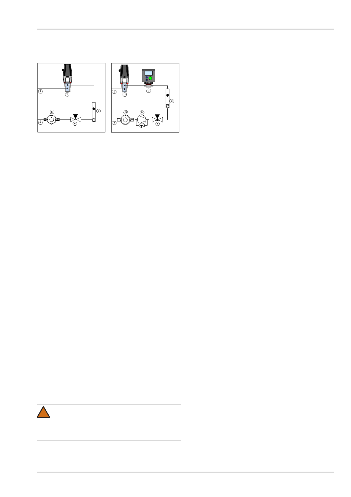
Example arrangements
Dräger SAM 3100 without
gas sampling pump:
1 Dräger PIR 7000 gas transmitter with process adapter
2 Sample gas outlet
3 Flow meter with ring initiator (flow monitoring at 25 to 250 l/h)
4 3/2-way calibrating gas valve
5 Analysis filter (filter element 1 µm PTFE)
6 Sample gas inlet
7 Dräger Polytron 7000 gas transmitter with adapter for
gas exposure
8 Gas sampling pump
Dräger SAM 3200 with gas
sampling pump:
3 Specification
Ambient temperature: +10 to +40 °C
Protection class: IP 20 (standard
Flow meter with ring initiator
Flow monitoring:
Standard: 10–100 l/h
Optional: 6–60 / 25–250 l/h
Material: PVDF
Sample gas lines
Material: Screw connections:
Gas sampling pump (option)
Power supply: 230 V / 50 Hz
Pumping rate: approx. 5.5 l/min.
Ejector (option)
Material: Stainless steel
Compressed air supply: 4 bar to 6 bar
configuration without
housing)
PVDF
Hose: PTFE
4 Settings
4.1 Air quantity
The flow should be set according to the sensor type:
Transmitter with electrochemical sensor ~60 l/h
Transmitter with electrochemical sensor + IR transmitter
in series ~80 l/h
IR transmitter ~180 l/h
The flow should be matched to the circumstances in the system
as a whole.
4.2 Standard system without delivery unit
The sample air leaves the process with excess pressure!
The sample gas flow should be set to 60 l/h at the fine
regulating valve on the flow meter. The top of the ball is the
read mark for the scale.
Notice on handling: see the Instructions for Use for the
flow meter.
4.3 System with ejector unit
To function correctly, the regulating valve needs an input
pressure of 1 bar to 10 bar. The control range of the
regulating valve is 0.2 bar to 10 bar.
Setting the sample gas flow:
Open the fine regulating valve on the flow meter (turn anti-
clockwise to the stop, then 1 turn back).
Set the flow approximately at the regulating valve, then carry
out the fine regulation using the regulating valve on the
flow meter . The top of the ball is the read mark for the scale.
Notice on handling: see the Instructions for Use for the
flow meter and for the regulating valve.
4.4 System with gas sampling pump
The sample gas flow should be set to 60 l/h at the fine
regulating valve on the flow meter. The top of the ball is the
read mark for the scale.
Setting the sample gas flow:
Open the fine regulating valve on the flow meter (turn anti-
clockwise to the stop, then 1 turn back), set the flow
approximately at the bypass valve on the gas sampling
pump, then carry out the fine regulation using the
regulating valve on the flow meter. The top of the ball is the
read mark for the scale.
Notice on handling: see the Instructions for Use for the
flow meter and for the gas sampling pump.
Regulating valve (option)
Input pressure: 1 bar to 10 bar
Control range: 0.2 bar to 10 bar
3/2-way spherical valve (option)
Material: Stainless steel
WARNING
The equipment is only approved for use in potentially
explosive atmospheres when using components
suitable for such areas, complete with test certificate.
Risk of explosion!
Test certificates are included in the equipment documentation.
4.5 Circuit breaker (option)
The circuit breaker is delivered together with the aspirator
system as a separate item. Installation is carried out on site
by the operator in accordance with the assembly
instructions. Information is included in the documentation.
The circuit breaker makes it possible to monitor line breaks
and short circuits. Furthermore, the action of the relay can
be reversed by means of a switch. Settings should be
adjusted in accordance with the operator's requirements
during commissioning. Information is included in
the documentation.
Standard: Auxiliary power 24 V DC
Optional: Auxiliary power 230 V, 50 Hz
Dräger SAM 3100/3200 5
Page 6

Installation
00423944_01.eps
123 4 5
00523944_01.eps
00623944_01.eps
00723944_01.eps
4.6 Motor circuit protector (option)
The motor circuit protector is delivered together with
the aspirator system as a separate item.
Adjustment range 0.25 to 0.4 A.
Using a screwdriver, set the value in accordance with
the rating plate on the motor of the gas sampling pump
(Ex pump 0.3 A, non-Ex pump 0.4 A).
Installation is carried out on site by the operator in
accordance with the assembly instructions. Information is
included in the documentation.
5 Installation
5.1 Mechanical fastening
The Dräger SAM 3100 / 3200 aspirator system is delivered
fully assembled.
The installation of the base plate or housing depends on
the local situation. Ensure that the installation is sufficiently
firm and free of vibration.
Connect the intake side to the hose laid by the customer,
using the compression fitting for a hose of 6 x 1 mm
(see section 5.2 on page 6).
The exhaust line is 6 x 1 mm as standard.
For exhaust lines more than 10 m in length, the cross-
sections should be expanded by the customer from the
outlet of the aspirator system in order to prevent pressure
build-up in the system.
Assembly instructions for PTFE hose connection
1 Screw-in piece 2 Nozzle
3 Clamping ring 4 Lock nut
5Hose
Slide the lock nut and clamping ring over the hose
as illustrated.
Slide the end of the hose over the nozzle to the stop.
5.2 Installing gas lines
The gas lines may only be connected by skilled personnel.
Local legislation and regulations must be observed.
When selecting gas lines (material, length), consider potential
adsorption effects.
When designing the length of the intake line, bear in mind
that a longer line will lengthen the alarm lag time.
Recommended hose material: PTFE (Teflon) or PE,
depending on the chemical resistance to the target gas.
When using other hose materials or diameters, a transition
to 6 x 1 mm PTFE hose must be created.
Cut off hose squarely!
Screw in the lock nut by hand until it is hand-tight.
To open the hose connection, unscrew the union nut and
remove the hose, together with the clamping ring, from the
aspirator system.
For air containing dust, an intake filter (order no. 68 06 743)
should be provided at the intake point to protect the aspirator
system and the line.
Avoid external influences such as splashing water, oil etc.
and the possibility of mechanical damage.
Pay attention to ventilation!
Always locate the intake point in the air flow between
a potential discharge or collection point and points of
potential hazard.
Pay attention to the density of gas!
For gases with a density lower than that of air, the intake
point must be located above any possible leak or at the
highest point at which large concentrations of gas may
occur. For gases and vapours with a density greater than
that of air, the intake point must be located below a possible
leak or at the lowest point at which such gases and vapours
may occur.
Pay attention to the seal of the gas connections, as leaks
can cause significant measuring errors to occur at the gas
transmitter.
When testing the seal, no overpressure or underpressure
should be generated at the sensor!
6 Dräger SAM 3100/3200
Page 7

5.3 Electrical connections
!
CAUTION
The electrics may be laid and connected only by
a specialist and whilst observing the relevant directives.
soldered connection
ring initiator
Installation
– +
– 1 +
5.3.1 Pump
For electrical installation works, the appropriate safety
regulations must be followed.
Before connecting the pump, ensure the electricity supply
is switched off.
The supply voltage should be checked against
the specifications on the rating plate on the gas
sampling pump. The supply voltage may deviate by
a maximum of +/– 10 % from the specifications on the
rating plate.
The earth wire should be connected to the gas
sampling pump. Install the gas sampling pump in such
a way that it is not possible to touch the live parts
(electrical connection).
A device for isolating the gas sampling pump from the
mains supply should be included in the electrical
installation. The electricity supply to the pump motor should
be protected with a fuse. The current consumption can be
found on the rating plate.
For systems with a gas sampling pump, a motor circuit
protector should be provided in the supply voltage cable,
without exception. The protection switch is installed in the
control cabinet. The motor circuit protector should be set to
the nominal motor current for the gas sampling pump
(see rating plate). Please note the manufacturer's technical
information (Instructions for Use are included in
the documentation).
limit value transmitter connection
00823944_en.eps
5.3.5 Connection cable:
The connection cables for the intrinsically safe circuit should
be selected according to the relevant installation standard.
In so doing, the formation of a summation current between
different intrinsically safe circuits of the float-type flow meter
should be prevented. When laying the cables, ensure sufficient
distance between the surfaces of the measuring component
and the connection cable.
5.3.6 Earth connection:
With float-type flow meters, when the flow impacts nonconductive components during operation this can cause
charge separation in the measuring tube. In the case of glass
equipment, it is, in principle, possible for the electrostatic field
generated within the measuring tube to penetrate through to
the outside of the equipment.
earthing
connection
5.3.2 Gas transmitter
Gas transmitters from Dräger are connected to a central
controller, e.g. Dräger REGARD, in accordance with
the specifications in the associated Instructions for Use
(see section 7 on page 8).
5.3.3 Flow meter with ring initiator
The flow meter is supplied provided with a connection
housing.
The cable is connected directly to the circuit breaker in
the control cabinet.
Please note the manufacturer's technical information
(see Instructions for Use for the flow meter).
5.3.4 Wiring diagram:
The electrical connection of the installed, intrinsically safe,
equipment to the + and – terminals is carried out in accordance
with the following illustration and table. A limit sensor is
connected to each terminal block. Pay attention to the
specified polarity.
01823944_en.eps
The float-type flow meter is connected to the installation plate
via the earth connection for the purpose of diverting
electrostatic charge. The earthing should be connected to the
local earth potential by the individual assembling the system as
a whole.
The operator is responsible fo r the uninterrupted earthin g
of the process line.
The connection merely ensures electrostatic earthing of the
equipment and does not meet the requirements for
equipotential bonding. When measuring dust-free gases
or liquids, the flow rate may not exceed 20 times the nominal
flow rate. Note the max. permissible operating pressure PS
printed on the rating plate.
Dräger SAM 3100/3200 7
Page 8

Maintenance
!
6 Maintenance
Dräger SAM 3100/3200 aspirator system:
The aspirator system is designed so as to minimise the need
for servicing.
Directions for maintenance and servicing can be found in
the Instructions for Use for the components used.
Depending on the dust load in the sample gas, the filter
inserts should be replaced when visibly soiled. Spare parts:
see the Instructions for Use for the filter.
In the case of systems with gas sampling pump, it is
recommended that the diaphragm and valve plates of the
pump are replaced at least once a year.
Spare parts: refer to the Instructions for Use for the gas
sampling pump.
The ejectors for delivering sample gas have no mechanical
parts subject to wear, and are therefore maintenance-free.
Gas transmitter
Maintenance and servicing of the gas transmitter should be
carried out according to the enclosed Instructions for Use.
The calibration interval and calibration i nstructions can be
found in the Instructions for Use for the gas transmitter and
for the DrägerSensor.
For aspirator systems with gas sampling pump, the pump
should be switched off during test gas feeding (calibrating).
For models with ejector, the air feed should likewise
be interrupted.
7 Wiring diagrams
CAUTION
Electrical wiring is only to be laid and connected by an
expert, paying attention to the relevant regulations and
laws concerning electrical equipment in potentially
explosive atmospheres as well as the approval
conditions.
Consult the Instructions for Use for installation!
8 Dräger SAM 3100/3200
Page 9

7.1 Wiring diagram for PEX 3000
02023944_en.eps
+24 Volts
0 Volt
Cable screen
contacted within
the cable gland
PEX 3000
Type XTR 0000,
XTR 0001,
XTR 0010
and XTR 0011
Cable screen
contacted within
the cable gland
PEX 3000
Type XTR 0090,
XTR 0091
Sensing head
Polytron SE Ex PR ... DD
Power supply
24 V 20 %,
0.15 A
4 to 20 mA
0 mA
Controller Unit
max. cable length
50 m
100 m
150 m
core cross-section
0.5 mm
2
1.0 mm
2
1.5 mm
2
12
3
12
3
Wiring diagrams
PEX 3000, all types PEX 3000, types XTR 0090 and XTR 0091
Connection to central controller: Connection to sampling head
Connect terminal +24 V to +24 volts Connect terminal br/br to terminal 1
Connect terminal SIG to 4 bis 20 mA input Connect terminal ge/yw to terminal 2
Connect terminal 0 V to 0 volts Connect terminal sw/bk to terminal 3
Dräger SAM 3100/3200 9
Page 10

Wiring diagrams
02423944_en.eps
Non-explosion-hazard areaExplosion-hazard area, zone 0, 1 or Div. 1
Safety barrier
Control unit
Ex i
PA
Earth point
4 ... 20 mA
0 V
+
–
+
4 to 20 mA
+24 V
!
!
02323944_en.eps
Non-explosion-hazard area
without a safety barrier
Control unit
4 ... 20 mA
0 V
+
–
+
4 to 20 mA
+24 V
Explosion-hazard area, zone 2 or non-explosion hazard
7.2 Wiring diagram for Polytron 3000 / Polytron 7000
Installing the transmitter in potentially explosive atmospheres of zone 0 or zone 1
Installing the transmitter in potentially explosive atmospheres of zone 2 or in areas not at risk of explosion.
WARNING
The category 1 classification must be cut out of the rating plate hanger at the location provided. Once the equipment has
been operated in accordance with this installation, it may n o longer be installed in mines in which firedamp may occur,
nor in potentially explosive atmospheres of zone 0 or zone 1 (equipment category 1 or 2). Risk of explosion!
Installing the transmitter in areas not at risk of explosion:
WARNING
The Ex protection classification must be removed from the transmitter. Once the transmitter has been operated in
accordance with this installation, it may no longer be installed in potentially explosive atmospheres.
10 Dräger SAM 3100/3200
Page 11

7.3 Wiring diagram for PIR 7000 / PIR 7200
2123944_en.eps
+
+
–
–
R
S
123456
power supply
red
black
brown
white
green/yellow
central device, e.g.
Dräger REGARD
02223944_en.eps
+
+
–
–
R
S
123456
power supply
red
black
brown
white
green/yellow
central device
Wiring diagram for operation as a 4 to 20 mA current source
(source operation):
Wiring diagram for operation as a 4 to 20 mA current sink
(sink operation):
Wiring diagrams
Dräger SAM 3100/3200 11
Page 12

List of materials
8 List of materials
Name Order no. Manufacturer
Gas transmitter and sensor type According to customer requirements Dräger
Aspirator system SAM 3100 / 3200
– Dräger
for a gas transmitter, comprising:
Base plate, 500 mm x 500 mm, stainless steel – Dräger
Filter, fine filter 1 µm 38.PC1410PVDF-ISW ISW
Flow meter with ring initiator,
monostable, flow monitoring
15. DK 800 PV K 1-MO
6–60 l/h
Krohne
10–100 l/h
25–250 l/h
All system hoses are PTFE, screw connections are PVDF, system is installed on the base plate.
Additional equipment:
Gas sampling pump, not for Ex areas PM21772-87 (N87 TTE) ISW (KNF)
Gas sampling pump, for Ex areas PM21773 -87 (N87 TTE Ex) ISW (KNF)
Protective housing, 500 x 500 x 300 mm,
plastic, filter mounted externally
Protective housing, 500 x 500 x 300 mm,
sheet steel, filter mounted externally
Protective housing, 500 x 500 x 300 mm,
stainless steel, for Ex areas, filter mounted externally
3/2-way spherical valve, stainless steel 02.SS-42 GXS 6 mm Swagelok
Ejector 01.710200.00VA ISW
Regulating valve 70.159.625 Festo
Isolation amplifier 24 V DC 03.160312 Steel
Isolation amplifier 230 V AC 03.160321 Steel
Motor circuit protector 0 to 0.4 A 115.072732 Eaton
KS 1453.600 Rittal
AE 1013.600 Rittal
AE 1013.600 Rittal
12 Dräger SAM 3100/3200
Page 13

Page 14

Page 15

Page 16

Dräger Safety AG & Co. KGaA
Revalstraße 1
23560 Lübeck, Germany
Tel +49 451 882 0
Fax +49 451 882 20 80
www.draeger.com
90 23 944 - GA 4675.790 de
© Dräger Safety AG & Co. KGaA
Edition 02 - September 2013 (Edition 01 - October 2006)
Subject to alteration
 Loading...