

Page 1
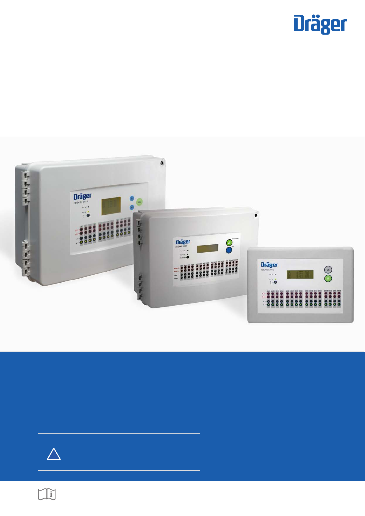
Regard 3900 Series
i
Sixteen Channel Controller
Instructions for Use
WARNING
Strictly follow the Instructions for Use. The user must fully
understand and strictly observe the instructions. Use the
!
product only for the purposes specied in the Intended
Use section of this document.
Dräger. Technology for Life
®
Page 2

This page intentionally left blank
Page 3

Contents
Contents
1 For your safety ................................................................................................................................................................4
1.1 General safety statements ................................................................................................................................................4
1.2 Definitions of alert icons ....................................................................................................................................................4
2 Description ......................................................................................................................................................................5
2.1 Product overview ..............................................................................................................................................................5
2.2 Intended use .....................................................................................................................................................................5
2.3 Limitations on use .............................................................................................................................................................5
2.4 Approvals ..........................................................................................................................................................................5
3 User information .............................................................................................................................................................7
3.1 Display screen ..................................................................................................................................................................7
3.2 Alarm, fault and active LEDs .............................................................................................................................................8
3.3 Power and inhibit LEDs .....................................................................................................................................................8
3.4 Internal sounder ................................................................................................................................................................8
3.5 External warning devices ..................................................................................................................................................9
3.6 Control buttons (and remote reset) ...................................................................................................................................9
3.7 LED and display screen test .............................................................................................................................................9
4 Technical information ...................................................................................................................................................10
4.1 General ...........................................................................................................................................................................10
4.2 Display board ..................................................................................................................................................................10
4.3 Input module ...................................................................................................................................................................11
4.4 Relay module ..................................................................................................................................................................11
4.5 Output module ................................................................................................................................................................12
5 Installation and set up ..................................................................................................................................................13
5.1 General instructions ........................................................................................................................................................13
5.2 Positioning and mounting the controller ..........................................................................................................................13
5.3 Cable entries ...................................................................................................................................................................14
5.4 Cable screen earthing plate ............................................................................................................................................14
5.5 Power supplies ................................................................................................................................................................15
5.6 Installing control modules ...............................................................................................................................................16
5.7 Connecting remote sensor transmitters ..........................................................................................................................20
5.8 Connecting other remote devices ...................................................................................................................................23
6 Conguringandcalibratingthecontroller .................................................................................................................25
7 Troubleshooting
7.1 Polytron remote sensor transmitter faults .......................................................................................................................27
8 Maintenance ..................................................................................................................................................................27
9 Disposal of electrical and electronic equipment .......................................................................................................27
10 Technical data ...............................................................................................................................................................28
10.1 Transfer function .............................................................................................................................................................29
11 Order list ........................................................................................................................................................................30
............................................................................................................................................................26
Annexe
A ConguringandcalibratingaRegard3920controller ..............................................................................................31
A.1 General ...........................................................................................................................................................................31
A.2 Main menu ......................................................................................................................................................................31
A.3 Information menu ............................................................................................................................................................32
A.4 Calibration menu .............................................................................................................................................................33
A.5 Settings menu .................................................................................................................................................................34
3Regard 3900 Series
Page 4
For your safety
1 For your safety
1.1 General safety statements
● Before using this product, carefully read the Instructions for Use.
● Do not dispose of the Instructions for Use. Ensure that they are retained and appropriately used by the product user.
● Only fully trained and competent users are permitted to use this product.
● Comply with all local and national rules and regulations associated with this product.
● Only trained and competent personnel are permitted to inspect, repair and service the product as detailed in these Instructions
for Use (see Section 8 on Page 27). Further maintenance work that is not detailed in these Instructions for Use must only be
carried out by Dräger or personnel qualied by Dräger. Dräger recommends a Dräger service contract for all maintenance
activities.
● Properly trained service personnel must inspect and service this product as detailed in the maintenance section of this
document.
● Use only genuine Dräger spare parts and accessories, or the proper functioning of the product may be impaired.
● Do not use a faulty or incomplete product, and do not modify the product.
● Notify Dräger in the event of any component fault or failure.
1.2 Denitionsofalerticons
Alert icons are used in this document to provide and highlight text that requires a greater awareness by the user. A denition of
the meaning of each icon is as follows:
WARNING
!
Indicates a potentially hazardous situation which, if not avoided, could result in death or serious injury.
CAUTION
!
Indicates a potentially hazardous situation which, if not avoided, could result in physical injury or damage to the product
or environment. It may also be used to alert against unsafe practices.
NOTICE
Indicates additional information on how to use the product.
i
i
4
Regard 3900 Series
Page 5
Description
2 Description
2.1 Product overview
The Dräger Regard 3900 series is a range of controllers that are used to continuously monitor up to sixteen 4–20 mA remote
sensor transmitters in order to warn of potentially dangerous or harmful conditions.
The series includes the Regard 3900, 3910 and 3920. The Regard 3900 and 3920 are sealed control panels, and the Regard
3910 is a modular system intended to be installed in a rack-based system. Other differences are explained in this document
where necessary.
The controller monitors the current signals from the remote sensor transmitters on input channels and provides warnings when
alarm or fault conditions occur. Each of the input channels can provide alarms for up to three gas levels (A1, A2 and A3) and two
fault conditions (F1 and F2). The gas-level alarms are congured to provide an indication of potentially dangerous or harmful gas
levels at the transmitter, and can be set to activate as the monitored gas levels are rising or falling. The faults (F1 and F2) operate
when the transmitter sends the relevant fault signal (F2 is only used when the transmitter provides a second fault signal).
The combination of internal control modules (input modules, relay modules and output modules) and the controller conguration
settings can be altered to meet the gas detection and warning requirements. Additionally the warning devices used with the
controller can be selected and congured as required by the user. The Regard 3900 series controllers are congured using a
Microsoft Windows
2.2 Intended use
Regard 3900 series controllers are used with 4–20 mA transmitters to provide stationary, continuous monitoring of ammable
or toxic gases and vapours, and oxygen deciency or enrichment. The controller is primarily intended for use as a part of a gas
detection system, but can be used with any remote sensor transmitter which uses a 4–20 mA source output (transmitters that
use a 4–20 mA sink output cannot be used). This document describes the Regard 3900 series used as a controller for a gas
detection system.
®
based software program. The Regard 3920 also has a built-in conguration system.
The controller is intended for use in residential, commercial and industrial environments to provide:
● Display of measured gas level.
● Visual and audible alarms at the controller and external warning devices.
2.3 Limitations on use
WARNING
The controller is not designed or approved for use in areas where combustible or explosive gases, vapours or dust mixtures
!
are likely to occur. Do not use the Regard 3900 series controller in areas subject to explosion hazards (“hazardous
areas”) without suitable protection. Contact Dräger for further information.
The controller cannot be used with three-wire transmitters that have a 4–20 mA sink output.
2.4 Approvals
The Regard 3900 series controller is certied according to the directive 94/9/EC (ATEX directive) to be operated with performance
approved 4–20 mA transmitters (EC-type examination certicate TRL 06 ATEX 21099X).
Output modules are not included in the scope of the Regard 3900 ATEX EC-type examination. Output modules shall not be used
for countermeasures against risk of explosion.
SpecialconditionsforsafeuseaccordingtoEC-typeexaminationcerticateTRL06ATEX21099X
1. Only remote sensor transmitters with valid and appropriate ATEX certication for safety and measurement performance shall
be connected to this control equipment. These connections may be via ATEX certied safety interface barriers.
2. Any cable used for interconnection of remote sensor transmitters should be selected to ensure that its resistance does not
have any adverse effects on the operation of the control unit.
Requirements of EN 60079-29-1
If a Regard 3900 series controller is used for ammable gas detection to protect against risk of explosion, at least one gas alarm
relay should be set latching. (See EN 60079-29-1:2007 Explosive atmospheres – Gas detectors – Performance requirements of
detectors for ammable gases.)
CEMarkingandATEXapproval
The Regard 3900 is CE marked to indicate conformity to the following directives:
● ATEX directive 94/9/EC
● EMC directive 2004/108/EC
● Low-voltage directive 2006/95/EC
5Regard 3900 Series
Page 6

Description
NOTICE
Using a power supply unit (PSU) not supplied or installed by Dräger may require reassessment of the compliance of the
i
i
controller with the EMC directive and/or the low-voltage directive.
ATEXMarking
The controller also has the following ATEX marking:
II (2) G
WARNING
This marking does not mean that the unit is “explosion proof”. The Regard 3900 series cannot be used in areas subject
!
to explosion hazards (“hazardous areas”) without suitable protection.
6
Regard 3900 Series
Page 7
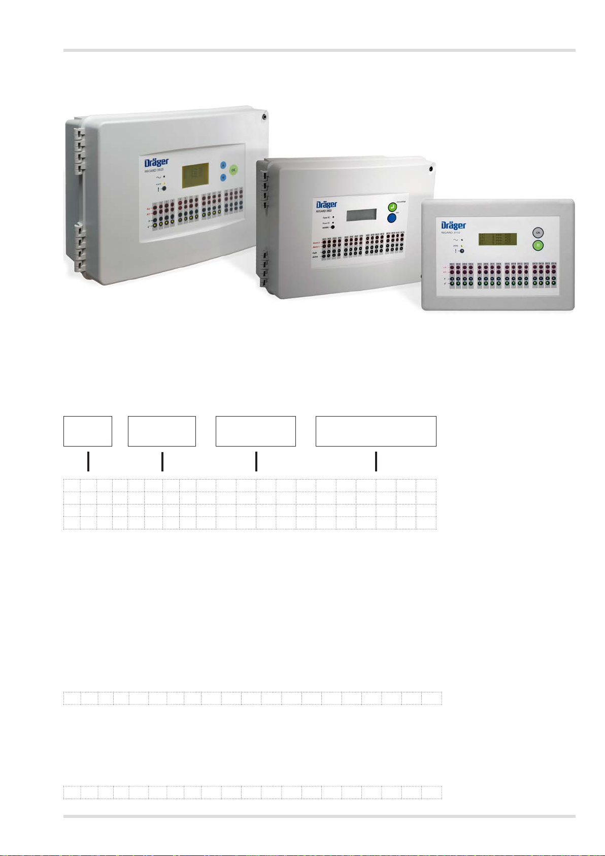
3 User information
Regard 3920
User information
Regard 3900
Regard 3910
3825
3.1 Display screen
The display screen is a multi-line, 20-character, backlit, LCD screen that provides information about the gases that the controller
is monitoring. During the normal gas-level display, the screen shows four lines of text.
Channel
identity
▼
0 1 : 0 % L E L M e t h a n
0 2 : 0 . 0 1 p p m C h l o r i
0 3 : 0 . 1 p p m H 2 S
0 4 : 1 2 3 4 p p b G a s n a m
● Very low gas levels of ± 2% of the measuring range are displayed as zero (this is referred to as the zero clamp).
● The display screen contrast is adjustable. Contact a trained maintenance technician or Dräger if adjustment is required.
3.1.1 Display screen scrolling
The display screen shows the information from up to four channels at a time, and if there are more than four channels installed,
the display screen scrolls to show all channels sequentially.
● Press Hold / II / ▲ for <1 second to freeze the display screen (stop scrolling).
● Press Hold / II / ▲ again for <1 second to unfreeze the display screen (restart scrolling).
Gas level Measurement
▼
units
▼ ▼
Gas name
or measuring range
3.1.2 Gas name or measuring range
The display screen can toggle between the gas name and the measuring range. The default is the gas name.
● Press Hold / II / ▲ for >1 second to show the full-scale deection (FSD) (the example below shows measuring range of 0–2000).
0 2 : 1 2 3 5 p p m ( 2 0 0 0 )
3.1.3 Over-range
Over-range is displayed if the gas level increases above the measuring range (the transmitter signal is above 20 mA). The overrange indication is latching (i.e. it remains on-screen even if the gas level returns into the measuring range).
● Press Acknowledge / OK (or operate the remote reset if available) to clear an over-range indication. If it is pressed when the
gas level is above the measuring range, the indication clears when gas level falls into the measuring range.
0 2 : O v e r - r a n g e
7Regard 3900 Series
Page 8
User information
3.1.4 Under-range
Under-range is displayed when the gas level is below the measuring range (the transmitter signal is below 3.8 mA – but not a
recognized maintenance or fault signal).
0 2 : U n d e r - r a n g e
3.1.5 Maintenance
Maintenance is displayed when transmitter maintenance is due (the transmitter signal is a recognized maintenance signal).
0 2 : M a i n t e n a n c e
3.2 Alarm, fault and active LEDs
WARNING
The alarm levels and the activation modes are congured to meet the requirements of the user. The actions and
!
countermeasures to be taken when any alarm or fault LED activates must be dened by the person responsible for the
gas detection system.
Although there are up to three gas-level alarms (A1 to A3) and two fault alarms (F1 and F2), there are no LEDs on the controller
for alarm A3 or fault F2. Remote warning devices can be congured to provide indications for alarm A3 and fault F2 when
required.
LED Condition
Alarm A1 Flashing
Alarm A2 Flashing
Fault F1 Flashing
Active /
Steady
Off
Steady
Off
Steady
Off
Steady
Blinking (off every 30 sec)
Off
A1 alarm tripped
A1 alarm acknowledged but alarm condition present
No alarm condition
A2 alarm tripped
A2 alarm acknowledged but alarm condition present
No alarm condition
F1 alarm tripped
F1 alarm acknowledged but fault present
Channel healthy
Channel active
Alarms inhibited
Channel inactive
(see also Inhibit / LED in Section 3.3)
3.3 PowerandinhibitLEDs
The power supply to the controller can be from an AC or DC power source or both. When both are used, the DC power source
(usually a battery system) is used as a backup supply in case of AC power supply failure.
Power AC /
It is optional to connect this LED when the controller uses both AC and DC power sources. When the LED is connected, it is
illuminated when the controller is supplied from the (primary) AC supply, and is off when the controller is supplied from the
(backup) DC supply.
Power DC /
Illuminates when there is a 24 Vdc supply to the internal control modules. (Irrespective of the power supply to the controller, the
internal control modules require a 24 Vdc supply.)
Inhibit/ LED
Illuminates to indicate that the alarms are inhibited, and therefore the normal gas-level monitoring and warning functions of
the controller are inactive. When the LED is illuminated, the Active /
30 seconds. Any remote warning device congured to activate when the alarms are inhibited would also activate.
LED
LED
LEDs blink off and the internal sounder beeps every
The alarms are inhibited when an internal inhibit switch is set to the maintenance position: usually for maintenance or repair of
the controller.
3.4 Internal sounder
The internal sounder emits an audible warning tone when A1, A2, A3, or F1 activates (not when F2 activates). The sounder also
beeps every 30 seconds when alarms are inhibited.
● Press Acknowledge / OK (or operate the remote reset if available) to silence the sounder.
8
Regard 3900 Series
Page 9
User information
3.5 External warning devices
External warning devices used with the Regard 3900 series controllers are activated by relays inside the controller, and are
congured to meet the user’s gas detection requirements. The relays can be congured to operate in a number of ways:
● Latching relays remain activated (in the alarm state) when an alarm condition has occurred but is no longer present.
● Non-latching relays deactivate (return to the non-alarm state) when an alarm condition is no longer present.
● Acknowledgeable relays can be manually deactivated (returned to the non-alarm state) when the alarm condition is still
present. This is used to switch off or silence external warning devices when the alarm condition is still present.
● Non-acknowledgeable cannot be deactivated when the alarm condition is present.
● Alarms inhibited relays activate when an internal inhibit switch is set to the maintenance position (see Inhibit / LED in
Section 3.3 on Page 4).
Latching or non-latching
Setting Meaning
Latching The relay requires manual action to reset after alarm activation.
Non-latching The relay automatically returns to the non-alarm state when the
Acknowledgeableornon-acknowledgeable
Press Acknowledge / OK or operate the remote reset:
• If the alarm condition is clear or if the relay is acknowledgeable,
the relay returns to the non-alarm state immediately.
• If the alarm condition is present, the relay returns to the non-
alarm state when the alarm condition clears.
alarm condition clears.
Setting Meaning
Acknowledgeable The relay can be reset manually when the alarm condition is
Non-acknowledgeable Relay cannot be reset manually. The relay automatically returns to
present.
Press Acknowledge / OK or operate the remote reset – the relay
returns to the non-alarm state.
the non-alarm state when the alarm condition clears.
3.6 Controlbuttons(andremotereset)
Acknowledge / OK
Acknowledges activated alarms, faults and display screen messages. When pressed, depending on the associated transmitter
signal and the controller settings:
● Alarm and fault LEDs on the controller extinguish or change to steady.
● The internal sounder is silenced.
● Display screen messages clear (for example: over-range).
● External warning devices remain activated or deactivate depending on the conguration.
Remote reset
A remote reset is a switch that performs the same functions as the Acknowledge / OK button, remotely from the controller.
Hold/II/▲
Controls the scrolling function and toggles between the gas name and the measuring range on the display screen.
● Press Hold / II / ▲ for <1 second to freeze and unfreeze scrolling (when more than four channels are used).
● Press Hold / II / ▲ for >1 second to toggle between the gas name and the measuring range.
Regard 3920 only
The ▲ / ▼ / OK buttons on Regard 3920 are also used to navigate and select settings within the built-in conguration menus
(see Annexe A on Page 30).
3.7 LED and display screen test
Pressing and holding two control buttons simultaneously tests the LEDs, display screen and internal sounder of the controller.
While the buttons are held, all LEDs illuminate (the Power AC /
segments ll and the sounder emits the alarm tone.
● Regard 3900: press Acknowledge and Hold
● Regard 3910: press OK and II
● Regard 3920: press OK and ▲
Use this function as a condence check of controller visual and audible outputs when required.
LED only illuminates if connected), all display screen
9Regard 3900 Series
Page 10
Technical information
4 Technical information
WARNING
!
This section and all subsequent sections contain technical and set-up information for trained maintenance technicians.
The procedures should not be attempted by untrained personnel as it could make the controller or gas detection system
unsafe for use.
4.1 General
The controller has a display board and up to six control modules. The control modules are a combination of input modules,
relay modules and output modules, which is exible within the limitations of the controller. Internally, all control modules and the
display board are connected together using a ribbon cable.
The controller can be supplied from an AC or DC source or both, and irrespective of the power supply to the controller the internal
control modules receive a 24 Vdc supply. The following internal LEDs operate during use:
● A green LED on each of the control modules illuminates to indicate that the internal DC voltage is supplied.
● Two red LEDs on the right-hand side of the display board and each of the control modules icker during normal operation.
● A red LED next to each relay on an input module or relay module illuminates when the relay is energized.
4.2 Displayboard
The display board is tted inside the controller, and houses the display screen and the LEDs that are visible on the front panel.
The display screen and LEDs provide information and warnings in response to the conditions measured at the remote sensor
transmitters. Also on the display board are the inhibit switch and the contrast control.
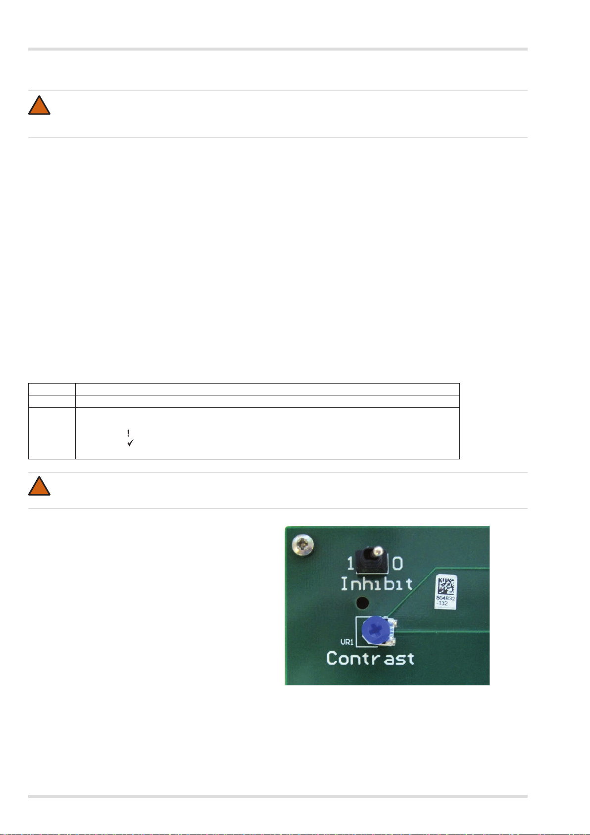
4.2.1 Inhibitswitch
The inhibit switch is used during maintenance or repair of the controller to hold the controller relays in their current state, and
thereby prevent activation of the gas-level warnings. The inhibit switch operates as follows:
Position Effect
0 All relays operate normally
1 Relays congured as “alarms inhibited” energize (associated remote warning devices activate).
!
4.2.2 Contrast control
The display screen contrast can be adjusted using the contrast
control. When required, use a suitable screwdriver to turn
the control to adjust the contrast. Note that LCD screens are
affected by temperature and adjustment may be required to
suit very cold or very hot environments.
All other relays are held in their current state.
The Inhibit /
The Active / LEDs blink off and the internal sounder beeps every 30 seconds.
Output module signals freeze at their current level.
WARNING
Setting the inhibit switch to position 1 holds the controller relays in their current state and prevents activation of gas-level
warnings. Always return the switch to position 0 after the maintenance or repair task.
LED illuminates.
10
3801
Regard 3900 Series
Page 11
Technical information
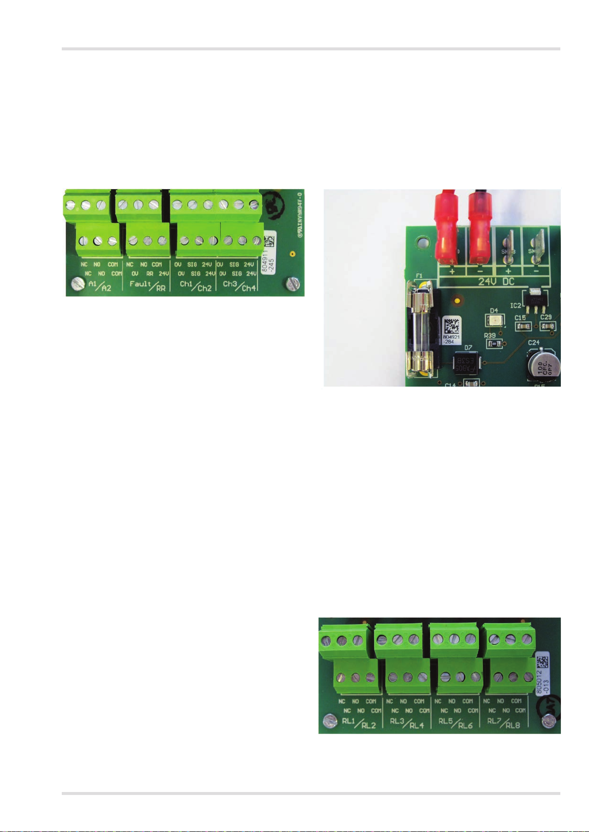
4.3 Input module
An input module has four channels that can each monitor the current signal from a remote sensor transmitter. Each of the
channels can provide alarms for up to three gas levels (A1, A2 and A3) and two fault conditions (F1 and F2). The gas-level
alarms are congured to provide an indication of potentially dangerous or harmful gas levels at the transmitter, and can be set to
activate as the monitored gas levels are rising or falling. The faults (F1 and F2) operate when the transmitter sends the relevant
fault signal (F2 is only used when the transmitter provides a second fault signal).
Each input module has three relays that operate when an F1 (fault 1), A1 (alarm 1) and A2 (alarm 2) signal is received from any of
the channels monitored by the board. The relays are volt-free single-pole changeover type that can be used to activate external
warning devices. The fuse on the input module protects the module against a short circuit on the input channels (Ch1 to Ch4).
3802
3803
The input module terminals are:
● Ch1 to Ch4 are channels for two-wire or three-wire 4–20 mA remote sensor transmitters.
● A1, A2 and Fault (F1) are terminals for the input module relays.
● RR are the remote reset terminals that are used to connect a normally-open switch, remote from the controller, to perform the
same function as the Acknowledge / OK button.
During installation, each input module is congured with a different module number (1–4) in order to set the channel numbers
(1–16) within the controller system (see Section 5.6.2 on Page 17).
Each input module requires a 24 Vdc supply using cables that are supplied with the module (see Section 5.6.3 on Page 18).
4.3.1 Input module relay settings
Input module relays settings are preset or can be set during conguration as follows:
● All input module relays are non-acknowledgeable.
● A1 and A2 relays energize on alarm.
● F1 relay is always (preset) normally energized.
● Each relay can be set latching or non-latching during conguration.
4.4 Relay module
A relay module is used to activate external warning devices
(alarms, ventilators or other safety equipment) when alarm or
fault conditions are sensed at the Regard 3900 series controller.
The module has eight volt-free single-pole changeover relays
of which one is a non-congurable system-fault relay (RL1)
and seven are congurable relays (RL2 to RL8).
RL1 to RL8 are the terminals for the relay module relays.
During installation, each relay module is congured with
a different module number (1 or 2) in order to set the relay
numbers (1–16) within the controller system (see Section 5.6.2
on Page 17).
3804
11Regard 3900 Series
Page 12
Technical information
4.4.1 Relay module relay settings
RL1 is used to indicate that a system-fault has occurred. For example: RL1 will de-energize if the ribbon cable is disconnected
from the relay module, or if an F1 fault signal is received from any remote sensor transmitter in the system. RL1 is preset to:
● Function: common F1
● Normally energized
● Latching
● Non-acknowledgeable
The other seven relays can be set during conguration to:
● Function: see table below
● Normally energized or energize on alarm
● Latching or non-latching
● Acknowledgeable or non-acknowledgeable
Function Relay changes state when
Common A1 A1 trips on any channel
Common A2 A2 trips on any channel
Common A3 A3 trips on any channel
Common F1 F1 trips on any channel
Common F2 F2 trips on any channel
Common A1, A2 or A3 A1 or A2 or A3 trips on any channel
Single A1 A1 trips on one specied channel
Single A2 A2 trips on one specied channel
Single A3 A3 trips on one specied channel
Single F1 F1 trips on one specied channel
Single F2 F2 trips on one specied channel
Voting A1 A1 trips on a specied number of channels in a group
Voting A2 A2 trips on a specied number of channels in a group
Voting A3 A3 trips on a specied number of channels in a group
Voting F1 F1 trips on a specied number of channels in a group
Voting F2 F2 trips on a specied number of channels in a group
Alarms inhibited
The inhibit switch on the display board is moved to position 1
No function Relay does not change state
4.5 Output module
An output module is used to send the current signals that are
received from the remote sensor transmitters to an external
monitoring device or system. The module has eight output
channels (Ch 1–8) that match the signals from the controller
input channels (either Ch 1–8 or Ch 9–16) (see Section 5.6.2
on Page 17).
+ Signal
- 0 V
The signal outputs and 0 V duplicate the input channel signals but are electrically isolated from the input channels. The signal
outputs are current source that will only work when connected to a passive load.
Input channel signal (mA) Display screen reading (0–100 range) Output channel signal (mA)
Below 3.8 Under-range or maintenance Matches input signal
1
3.8 to 4.2 0 4.0 (zero clamp
)
4.3 2 4.3
12 50 12
20 100 20
Above 20 Over-range Matches input signal
Input channel inactive Not applicable 0
Note 1: The zero clamp provides a 4 mA output signal for very low gas levels of ± 2% of the measuring range.
Alarmsinhibit
If the inhibit switch is set to position 1 the output signals freeze at their current level. When the inhibit switch is returned position 0
the output signals return to the normal level.
3805
Output module fault
If the output module has a fault, the output signal on all channels is 1 mA (± 0.3 mA).
12
Regard 3900 Series
Page 13

403 mm (15.9 in.)
305 mm (12.0 in.)
Installation and set up
5 Installation and set up
5.1 General instructions
The following general instructions should be observed for all installation, repair or maintenance tasks on the controller. Refer also
to the remote sensor transmitter operating manual for information about the transmitters and sensors.
WARNING
!
Disconnect or switch off all AC and DC supplies to the controller before attempting installation, repair or maintenance
tasks on the controller. Failure to disconnect the power supply may result in personal injury and/or may damage the
controller, remote sensor transmitter, or wiring.
1. Disconnect or switch off all AC and DC supplies to the controller.
2. Remove the two cover screws (5 mm hexagonal key) and open the front cover.
3. Carry out the necessary installation, repair or maintenance task.
4. Check the sealing ring and close the front cover.
5. Ret and secure the two cover screws.
5.2 Positioning and mounting the controller
WARNING
!
The Regard 3900 series controllers are not “explosion proof” and must not be installed in a hazardous area without
additional Ex-protection.
Observe the following instructions regarding the installation environment:
● Locate the controller where it is accessible, and the display screen and indicators are easily seen.
● Avoid locations where excessive vibration (frequency above 55 Hz or amplitude above 0.15 mm (0.006 in.)) is possible.
● Avoid locations where aggressive or corrosive gases, contaminants or pollutants harmful to electronic equipment are present.
● Temperature conditions: 0 to 55 °C (32 to 131 °F).
● Relative humidity: Regard 3900/3920 – 0 to 100%, non-condensing; Regard 3910 – 0 to 95%, non-condensing.
5.2.1 Regard 3900 and 3920
A A
B
C
B
120 mm (4.7 in.)
210 mm (8.3 in.)
250 mm (9.8 in.)
B B
A
C
A
Mounting template – Dimensions not to scale
A M6 x 10 mm (0.4 in.) threaded hole
B Mounting hole
C Hanger
240 mm (9.4 in.)
300 mm (11.8 in.)
3807
13Regard 3900 Series
Page 14

Installation and set up
CAUTION
!
If the controller is mounted using the mounting holes (B), remove all control modules to prevent damage when drilling the
holes in the panel.
Observe normal precautions if drilling into walls or other structures to avoid damage to existing wiring, gas pipes, water
pipes, etc.
The panel requires a space of at least 50 mm (2 in.) on the left-hand side to allow the front cover to open. Dräger recommend a
space of at least 50 mm (2 in.) around the entire panel.
Mount the panel using the following as required:
● Use the M6 threaded holes (A) or the hangers (C) to maintain the ingress protection rating (IP 65) of the panel.
● Drill through the mounting holes (B) using a 5 mm (3/16 in.) drill bit. Drilling the mounting holes reduces the ingress protection.
● A mounting bracket that maintains the ingress protection rating of the panel is available from Dräger. The bracket is supplied
with the screws and washers required to t the bracket to the threaded holes (A) on the rear of the panel (see Section 11 on
Page 29 for the part number).
5.2.2 Regard 3910
Separate Assembly Instructions are supplied with the Regard 3910 controller.
5.3 Cableentries
CAUTION
Do not attempt to knock out cable entries as it may crack the control panel casing. Take care when cutting the cable
!
entries to avoid damaging internal components and wiring, and remove control modules to prevent damage when drilling
if necessary.
1. Select the cable hole on the top or bottom of the panel casing which is adjacent to the cable termination inside the panel.
2. Use an M20 hole cutter to cut out the pre-marked cable hole.
3. Insert the cable and t an M20 cable gland to seal the cable hole and prevent moisture ingress.
5.4 Cablescreenearthingplate
An earthing plate is available from Dräger to earth cable screen inside the panel of the Regard 3900 and 3920. When used,
connect the plate to an external low-impedance earth using braided cable with a large cross-section. Note that the earthing plate
is not required for the controller to meet the EMC directive.
14
Regard 3900 Series
Page 15

Installation and set up
5.5 Power supplies
The external power supply to the controller can be from an AC or DC power source or both. When both are used the DC power
source is used as a backup supply and can be a 24 Vdc supply or a 24 V battery. The specication and tolerances for AC and
DC power sources is shown in the technical data (Section 10 on Page 28).
5.5.1 AC Supply
NOTICE
i
i
If the internal 24 Vdc power supply unit (PSU) is not provided by Dräger, ensure that it meets the EMC (electromagnetic
compatibility) directive and the LVD (low-voltage directive) requirements. The PSU must also meet the following EMC
standards – immunity: EN 61000-6-2; emissions: EN 61000-6-3 or EN 61000-6-4.
If the AC supply to the controller is from an AC socket, the maximum length of cable between the socket and the controller
is three metres (9.8 feet).
For an AC power supply, use a 24 Vdc PSU connected as shown below. The PSU should be selected depending on the number
of input channels used. Dräger recommend the following:
● 4 channels – 2 A PSU.
● 8 channels – 5 A PSU.
● 12 or 16 channels – 10 A PSU.
AC on
+24 Vdc to
input modules
0 V
+24 V
L
N
E
External
230 Vac
in
Sk2
Display board
5.5.2 DC Supply
To supply the controller from an external DC supply:
● Use a regulated interference-free 24 Vdc supply.
● If the supply could be subject to high levels of conducted RF interference, use a lter to remove the interference.
● If HART (highway addressable remote transducer) diagnostics can be used for the remote sensor transmitters, the supply
must conform to the HART requirements (refer to the remote sensor transmitter operating manual).
AC on
230 Vac 24 Vdc PSU
+24 Vdc to
input modules
0 V
+24 V
3808
External
24 Vdc
in
Sk2
Display board
Fused
terminals
3810
15Regard 3900 Series
Page 16

Installation and set up
5.5.3 AC and DC Supplies
When used together, AC is the primary supply and DC is the backup supply. Diodes and/or relays may be required to switch
between the primary and the backup supplies.
Power AC /
When the controller is supplied with both AC and DC, it is optional to connect the 24 Vdc output from the PSU to the AC on
terminal on Sk2 on the display board. When connected, the Power AC / LED is illuminated when controller is supplied from
the (primary) AC supply, and is off when the controller is supplied from the (backup) DC supply. Note that a diode is required to
prevent current ow from the backup supply falsely indicating a functioning AC supply.
LED
AC on
Optional
0 V
+24 V
L
N
E
External
230 Vac
in
Sk2
Display board
0 V
24 Vdc to
input modules
+24 V
0 V
+24 V
External
24 Vdc or
battery
3811
5.6 Installing control modules
WARNING
Output modules are not included in the scope of the Regard 3900 ATEX EC-type examination. When an output module
!
is tted, the controller cannot be used for control of countermeasures against risk of explosion.
The controller can have up to six control modules using the combinations detailed in Section 5.6.1. When tting control modules
observe the following:
● Use the short pedestal screws for the lower level; use the long pedestal screws for the middle level; and use the long pedestal
screws and the plastic spacers for the upper level. (All of the screws have M3 threads.)
● Do not connect control modules outside the control panel of Regard 3900 and 3920 controllers.
● Refer also to the separate Assembly Instructions supplied for tting control modules to a Regard 3910 controller.
Example showing two input modules and one output module
16
3812
Regard 3900 Series
Page 17

Module Nr.
Installation and set up
5.6.1 Controlmodulecombinations
The combination of control modules must meet the following conditions:
● A maximum of six control modules (input, relay and output modules combined)
● A maximum of four input modules.
● A maximum of two relay modules.
● A maximum of four input modules and relay modules combined.
● A maximum of four output modules.
The table below shows the combinations. Using the highlighted row in the table as an example, the controller could have: three
input modules (up to 12 input channels); a single relay module (up to 8 relays); two, one or no output modules (16, 8 or 0 output
channels).
Input
module
4 0 2
3 1 2
3 0 3
2 2 2
2 1 3
2 0 4
1 2 3
1 1 4
1 0 4
5.6.2 Numberingcontrolmodules
!
Input modules
Place a link on the relevant “Module Nr” terminals on the input module to determine the channel numbers in the Regard 3900
system. When numbering the input module observe the following:
● Each input module within the controller must have a different module number (1 to 4).
● If there is only one module tted, set it as number 1.
● Number modules in sequence or difculty will occur when trying to congure the system.
Relay
module
WARNING
Renumbering an input or relay module (by moving the link on the module) after conguring the controller could prevent
alarms from activating as required. If an input or relay module is renumbered, recongure the controller to ensure that
alarms activate as required.
Maximum
number
of output
modules
1
2
3
4
3813
Link
position
1 1 – 4
2 5 – 8
3 9 – 12
4 13 – 16
Channels
17Regard 3900 Series
Page 18

Installation and set up
Relay modules
Place a link on the relevant “Relays” terminals on the relay module to determine the relay numbers in the Regard 3900 system.
When numbering the relay module observe the following:
● If there is only one relay module tted, place the link on position 1–8.
● If a second relay module is tted, place the link on position 9–16.
1 - 8
2
3
Relays
9 -16
3814
Link
position
1-8
Relay on
module
RL1
RL2
RL3
RL4
RL5
RL6
RL7
RL8
Number
in
system
1
2
3
4
5
6
7
8
Link
position
9-16
Relay on
module
RL1
RL2
RL3
RL4
RL5
RL6
RL7
RL8
Number
in
system
9
10
11
12
13
14
15
16
Output modules
Place a link on the relevant “Channels” terminals on the output module to determine the channel outputs: 1–8 or 9–16. Two or
more output modules can be set to the same channels if required.
1 - 8
2
3
9 -16
Channels
5.6.3 Controlmoduleanddisplayboardwiring
Input module 24 Vdc supply
Connect all input modules to the internal DC supply using the cables supplied with the module. Connect the rst input module
using the long (PSU to module) cables, and connect subsequent input modules in parallel using the short (module to module)
cables as shown.
3815
18
3809
Regard 3900 Series
Page 19

Installation and set up
Ribboncable
Connect the ribbon cable to the display board and to all control modules, using the standard ribbon cable supplied by Dräger.
The display board, relay modules and output modules do not require a separate DC supply.
Note: For Regard 3910 non-standard cable lengths can be supplied by Dräger. The maximum permitted length of the ribbon
cable is 2 metres (6.6 feet).
3816
19Regard 3900 Series
Page 20

Installation and set up
5.7 Connecting remote sensor transmitters
The wiring diagrams in this section show the general wiring layout for remote sensor transmitters. Refer to the remote sensor
transmitter operating manual for the specic details about the remote connections, including terminal marking, colour coding,
lettering, etc.
Observe the following for all transmitter types:
● The cable cross-section for transmitter wiring is a maximum 2.5 mm2 (0.004 in.2) and a minimum 0.5 mm2 (0.0008 in.2).
● Use screened cable if required by the transmitter.
5.7.1 Two-wire 4–20 mA transmitters
Input module
Ch1 Ch2 Ch3 Ch4
0 V SIG 24 V 0 V SIG 24 V 0 V SIG 24 V 0 V SIG 24 V
20
+24 V
4–20 mA signal
Channel 1
+24 V
4–20 mA signal
Channel 2
+24 V
4–20 mA signal
Channel 3
+24 V
4–20 mA signal
Channel 4
3817
Regard 3900 Series
Page 21

Installation and set up
5.7.2 Two-wire4–20mAtransmitterswithsafetybarrier
● Refer also to the instructions for the safety barrier and transmitter for connections between transmitter and barrier, and for
the barrier earth connection.
Hazardous area
Transmitter
+24 V
Signal
Non-hazardous area
Safety barrier
0 V
+24 V
Ex i
0 V
Signal
Input module
RR Ch1
0 V RR 24 V 0 V SIG 24 V
3819
21Regard 3900 Series
Page 22

Installation and set up
5.7.3 Three-wire 4–20 mA transmitters
● Only connect transmitters that have a 4–20 mA source output. Regard 3900 cannot be used with a three-wire transmitter that
has a 4–20 mA sink output (if necessary use a sink-to-source converter).
● The module can supply up to 400 mA to a three-wire transmitter.
● Use a cable where the three cores each have the same resistance.
● To ensure that a short circuit between the 4–20 mA signal output and the 0 V wire at the transmitter causes a fault indication
at the controller, each cable core must not exceed the resistance given by the formula:
R
cable = 250 x Ifault
Itxr
Rcable is the maximum resistance per core from the controller to the transmitter (in Ω).
I
fault is the fault trip level (in mA).
I
txr is the transmitter operating current (in mA).
Example using a transmitter with an operating current of 100 mA and a fault trip level of 3.2 mA.
Rcable = 250 x 3.2 = 8 Ω per core
100
Input module
Ch1 Ch2 Ch3 Ch4
0 V SIG 24 V
0 V SIG 24 V
0 V SIG 24 V
0 V SIG 24 V
22
0 V
4–20 mA signal
Channel 1
+24 V
0 V
4–20 mA signal
Channel 2
+24 V
0 V
4–20 mA signal
Channel 3
+24 V
0 V
4–20 mA signal
Channel 4
Regard 3900 Series
+24 V
3820
Page 23

Installation and set up
5.8 Connecting other remote devices
● The cable cross-section for remote devices is a maximum 2.5 mm2 (0.004 in.2) and a minimum 0.5 mm2 (0.0008 in.2).
5.8.1 Remote reset
A remote reset is a switch that performs the same functions as the Acknowledge / OK button remotely from the controller (see
Section 3.6 on Page 9). When a remote reset is required:
● Connect a normally-open switch to the remote reset (RR) terminals of an input module.
● If more than one input module is installed, it is sufcient to connect the remote reset switch to only one input module.
Input module
RR
0 V RR 24 V
3821
5.8.2 Relay terminals (input and relay modules)
The relay terminals on input modules (A1, A2 and Fault (F1)) and relay modules (RL1 to RL8) can be used to provide a switching
function for remote warning devices such as alarms, ventilators or other safety equipment. When connecting remote devices
observe the following:
● The voltage and current ratings of the relay contacts are shown in the technical data (see Section 10 on Page 28).
● Use screened or unscreened cable for relay outputs.
● When an internal supply is required to drive the external device, use an output from the power supply unit (PSU).
● The gures below show the relay contacts when relays are in the non-alarm or non-fault state.
NC NO COM
NC NO COM
Input or relay module
Energize on alarm
Input or relay module
Normally energized
3822
23Regard 3900 Series
Page 24

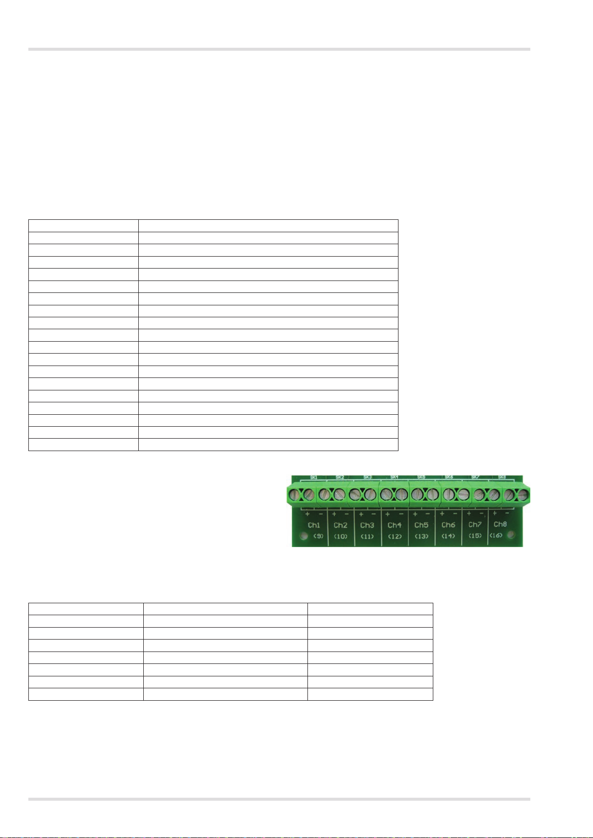
Output module
+ –
Ch1 Ch2 Ch3 Ch4
(9) (10) (11) (12)
Channel 1
+
–
+ –
+ – + –
Channel 2
+
Channel 3
+
Channel 4
+
External device
–
–
–
Installation and set up
5.8.3 Output module terminals
The output module terminals (Ch1 to Ch8) are used to output the corresponding remote sensor transmitter signal to an external
monitoring device or system.
● Each channel output is a current source that will only work when connected to a passive load.
3823
24
Regard 3900 Series
Page 25

Conguring and calibrating the controller
6 Conguringandcalibratingthecontroller
The conguration and calibration tools for Regard 3900 series controllers are used to view and change the conguration of the
controller, including the combination of internal control modules and the settings for the gas detection and warning devices. The
tools also allow zero point and span calibration.
Congure and calibrate the controller for all channels during initial installation and then when required during maintenance or
repair of the controller or gas detection system.
After completing any conguration or calibration, ensure that all alarms and warning devices operate as intended.
Congurationandcalibrationtools
For Regard 3900 and 3910, use the Dräger Regard 3900 Conguration Software. The software is a Microsoft Windows based
program that requires an interface unit (RS-232) and a compatible PC. The software and interface unit are available from Dräger.
See the Instructions for Use supplied with the software for full instructions.
For Regard 3920, use the built-in conguration system (see Annexe A on Page 30). Regard 3920 can also be congured using
the Dräger Regard 3900 Conguration Software if required.
25Regard 3900 Series
Page 26

Troubleshooting
7 Troubleshooting
Symptom Fault Remedy
Display screen blank and all LEDs off No supply to controller Check and repair the external supply
Faulty power supply unit Replace power supply unit
Internal wiring fault Check and repair internal power
Display screen blank No supply to display board Check and reconnect ribbon cable to
Display screen shows: NO INPUTS Ribbon cable fault Repair or replace ribbon cable
Display screen shows:
4–20 BOARD ERROR or
RELAY BOARD ERROR or
OUTPUT BOARD ERROR
LED and display screen test fails Faulty display board Replace display board
Power DC /
display screen on
Display screen shows: Under-range Faulty transmitter connection Check and repair the transmitter wiring
Display screen shows: Over-range Short-circuit remote sensor transmitter
Fault (F) LED illuminated for a single
channel
Fault (F) LED illuminated for a group of
four channels.
Input module tted, but no LEDs
illuminated or data on the display
screen for the module
Controller gas level different to the
level displayed at the remote sensor
transmitter
Fault (F) LED illuminated (steady) or
ashing when channel inactive
Water ingress Faulty seal Check and repair the cover sealing
LED not illuminated, but
Faulty input, relay or output module Replace the faulty module
Controller supply fault Check and repair the external or
Faulty display board Replace display board
Incorrect loop current Recalibrate
Faulty transmitter Replace the transmitter
wiring
Remote sensor transmitter fault Check and repair the transmitter
Transmitter wiring fault Check and repair the transmitter wiring
Incorrect loop current Recalibrate
Faulty transmitter Replace the transmitter
Faulty input module Replace input module
Transmitter wiring fault Check and repair the transmitter wiring
Ribbon cable fault Check and repair/replace ribbon cable
Faulty input module Replace input module
Ribbon cable fault Check and repair/replace ribbon cable
Internal wiring fault Check and repair internal power
Faulty input module Replace input module
Faulty display board Replace display board
Transmitter calibration fault Recalibrate
Input channel calibration fault Recalibrate
Input channel range incorrectly set Set the input channel range the same
Conguration error
and wiring
distribution wiring
display board and all modules
Replace display board
internal 24 Vdc supply
Check and repair the transmitter wiring
distribution wiring
as the transmitter range
Set the inhibit switch to position 1, then
return it to position 0
ring, cable entries and the front cover
information label
Output module faults
No signal from all outputs; green LED
not illuminated
No signal from all or some outputs;
green LED illuminated
Output is constant at 1 ± 0.3 mA. No signal from input modules Check and connect/repair the ribbon
Output constant but gas-level on
display screen changing
Output signal too low or will not reach
20 mA
26
No supply to module Check and connect/repair ribbon cable
Faulty output module Replace output module
Incorrect channels selected on output
module
Faulty output module Replace output module
Alarms inhibited
Load resistance too high Reduce load resistance
to module
Move link to the correct terminals on
the output module
cable
Return inhibit switch to position 0
Regard 3900 Series
Page 27

Troubleshooting
Symptom Fault Remedy
DrägerRegard3900CongurationSoftwarefaults
Unable to transfer conguration to or
from the controller
Calibration failure message on screen Remote sensor transmitter fault Check and repair the transmitter wiring
No supply to controller Check and repair the external supply
and wiring
Interface unit (RS-232) fault Check and repair/replace the interface
unit
and recalibrate
7.1 Polytron remote sensor transmitter faults
Polytron warning signal
The Polytron transmitter warning signal (3 mA for 1s every 10s) will trip the Fault (F1) relay on the input module if the trip level is
set above 2.9 mA. If the fault relay is non-latching, the relay will change state momentarily every 10s in time with warning signal.
Because the duration of the 3 mA signal is short, it may not trip the relay every time. If this occurs, refer to the remote sensor
transmitter operating manual.
Polytron maintenance signal
The maintenance signal on older Polytron transmitters (3~5 mA at 1 Hz) will trip the Fault (F1) relay on the input module if the
trip level is set above 2.9 mA. If the fault relay is non-latching, the fault relay will toggle. If this occurs, refer to the remote sensor
transmitter operating manual.
8 Maintenance
Observe EN 60079-29-2 and any relevant national regulations in the country of use.
There are no specic maintenance tasks for the Regard 3900 controller. Carry out any maintenance or calibration tasks in line
with the instructions and frequency described in the remote sensor transmitter operating manual.
NOTICE
During maintenance the inhibit switch on the display board can be used to hold the controller relays in their current state,
i
i
and thereby prevent activation of the gas-level warnings. See Section 4.2.1 on Page 10 for the inhibit switch operating
instructions.
9 Disposal of electrical and electronic equipment
EU-wide regulations for the disposal of electrical and electronic equipment, which have been dened
in the EU Directive 2002/96/EC and in national laws, are effective from August 2005 and apply to this
device. Common household appliances can be disposed of using special collecting and recycling facilities.
However, as this device has not been registered for household usage it must not be disposed of through
these means. The device can be returned to your national Dräger Safety Sales Organization for disposal.
Please do not hesitate to contact Dräger if you have any further questions about this issue.
27Regard 3900 Series
Page 28

Technical data
10 Technical data
Control panel versions (Regard 3900 and 3920)
Dimensions 415 × 305 ×
Weight Approximately 5 kg (11 lb)
Material ABS – VO
Ingress protection IP65
Cable entries M20 (qty 30)
All versions
Cable cross-section
AC input voltage (to PSU)
AC current consumption Typical Maximum
DC input voltage 18 to 30 Vdc
DC current consumption @ 24 V Input module: 60 mA excluding transmitters
Visual and audible outputs Visible: LEDs and display screen
Storage temperature -25 to 70 °C (-13 to 158 °F)
Operating temperature 0 to 55 °C (32 to 131 °F)
Relative humidity (RH) – operating
and storage
Start-up time
Response time <2 seconds
Accuracy Within 1% of measured value
Module xings M3
Maximum 2.5 mm2 (0.004 in.2)
Minimum 0.5 mm2 (0.0008 in.2)
Typical: 98 to 253 Vac, 50 to 60 Hz
2 A PSU < 0.5 A 0.5 A
5 A PSU 0.5 A 1 A
10 A PSU 1 A 2 A
Relay module: 200 mA
Output module: 300 mA
Display screen: 170 mA
Interface unit (RS-232): 50 mA
Audible: Sounder
Regard 3900/3920: 0 to 100%, non-condensing
Regard 3910: 0 to 95%, non-condensing
<40 seconds
175 mm (16.3 x 12 x 6.9 in.)
Relays (all modules)
Type Volt-free single-pole changeover
Contact material Silver alloy
Nominal switching capacity
Maximum switching power 1250 VA; 150 W
Switching voltage Maximum: 250 Vac; 100 Vdc
Switching current Maximum: 5 A
Output module
Output range
Isolation 50 V
Resolution 0.1 mA
Accuracy Within 1% of input signal (less zero clamp)
Maximum load
Storage temperature -25 to 70 °C (-13 to 158 °F)
5 A 250 Vac; 5 A 30 Vdc
Minimum: 10 V
Minimum: 100 mA
0.1 to 21.7 mA
500 Ω
28
Regard 3900 Series
Page 29

10.1 Transfer function
100
Gas concentration (% LEL)
Input signal Display reading
> 20.0 mA Over-range
4.3 to 20 mA Linear gas reading according to selected range
3.7 to 4.3 mA 0
< 3.7 mA Under-range or maintenance, depending on fault trip level
Gas concentration reading for 0–100 % LEL
80
60
Technical data
40
20
0
4 6 8 10 12 14 16 18 20
Input signal (mA)
3904
29Regard 3900 Series
Page 30

Order list
11 Order list
NOTICE
Regard 3800 series components are not compatible with the Regard 3900 series. Always refer to the relevant Regard
i
i
series order list when ordering parts and accessories.
Description Quantity Order code
Regard 3900 (control panel with display board) 1 4208780
Regard 3910 (bezel assembly with display board) 1 4208830
Regard 3920 (control panel with display board) 1 4208850
Display board (Regard 3900 and 3910) 1 4208781
Display board (Regard 3920) 1 4208856
Input module 1 4208782
Relay module 1 4208784
Output module 1 4208797
Dräger Regard 3900 Conguration Software 1 4208804
Interface unit (RS-232) 1 4208785
Ribbon cable 1 4208750
Power cable long (PSU to module) 1 (pair) 4208792
Power cable short (module to module) 1 (pair) 4208791
Earthing plate 1 4208777
Mounting bracket 1 4208796
Instructions for Use (English) 1 4208800
Instructions for Use (German) 1 4208801
Instructions for Use (French) 1 4208802
Instructions for Use (Spanish) 1 4208803
30
Regard 3900 Series
Page 31

Conguring and calibrating a Regard 3920 controller
A ConguringandcalibratingaRegard3920controller
A.1 General
The built-in conguration system in the Regard 3920 allows the user to view and change the controller conguration, including
the combination of internal control modules and the settings for the gas detection and warning devices. The system also allows
zero point and span calibration.
Entry into the conguration system is password protected and there are two entry levels. The calibration level is used when only
calibration is required, and the settings level is used when altering controller settings and calibration are required. The initial entry
passwords are shown below, and changing passwords is described in the settings menu (see Section A.5 on Page 19).
Calibration: _ _ _ 1
Settings: _ _ _ 2
To enter and use the conguration system:
1. Press ▼ for >1 second and then press OK to open the Enter password screen.
2. Enter the password and then press OK to open the main menu.
01: 20.9 %vol Oxygen
02: 14 ppm H2
03: 0 %LEL CH4
04: 4 ppb H2S
3. Use the ▲ / ▼ / OK buttons to navigate and select settings as shown in table below.
Key Function
OK Accept menu items and characters
▲ Navigate up/back in the menus and character lists
▼ Navigate down/ forward in the menus and character lists
When using the conguration system, note the following:
● Before conguring the controller, ensure that all input, relay and output modules are correctly numbered (see Section 5.6.2
on Page 11).
● Alarms are automatically inhibited when a conguration menu is open.
● Changes made during conguration are saved automatically.
● The display screen automatically returns to the gas-level display if a key is not pressed for 10 minutes.
►
Enter password
_ _ _ 2
↑ Exit
- Language
+ Information
►
+ Calibration
+ Settings
A.2 Main menu
Main menu
Exit
Language
Information
Calibration
Settings
Exit – Returns to the normal gas-level display.
Language – Selects the on-screen language (the settings menu is always in English).
Information
Calibration– Enters the calibration menu (see Section A.4 on Page 32).
Settings – Enters the settings menu (see Section A.5 on Page 33).
– Enters the information menu (see Section A.3 on Page 31).
31Regard 3900 Series
Page 32

Conguring and calibrating a Regard 3920 controller
A.3 Information menu
Information
Test LEDs
Tags
Modules
Test LEDs – Activates the LED and display screen test (see Section 3.7 on Page 9). Press OK to start and stop the test.
Tags – Displays all channel tags (read only).
Modules – Displays all module types and versions (read only).
32
Regard 3900 Series
Page 33

A.4 Calibrationmenu
Calibration
Module 1
Channel 1
Channel 2
Channel 3
Channel 4
Module 2
Conguring and calibrating a Regard 3920 controller
Tag
Zerocalibration
Spancalibration
Gas concentration
Signal mA
Channel 5
.
.
.
Channel 8
Module 3
Module 4
Use the calibration menu to calibrate the controller for all channels during initial installation and then when required during
maintenance or repair of the controller or gas detection system. Refer also to the remote sensor transmitter operating manual
for transmitter calibration instructions.
In the chart above, the Module 1 menu is expanded to show the zero and span calibration menus for Channel 1. Depending
on the number of modules congured as input modules, Channels 5 to 16 would be available on Modules 2, 3 and 4. The chart
shows Module 2 congured as an input module.
Tag – Displays the channel tag (read only).
Zerocalibration–Before calibrating the channel, it is mandatory to calibrate the transmitter to ensure that the transmitter output
signal is 4 mA for a zero gas reading.
1. Select Zerocalibration for the relevant channel.
2. Select Calibratechannel.
○ When the success message appears, exit the menu to save the calibration.
○ If a failure message appears, refer to the troubleshooting information (see Section 7 on Page 26).
Spancalibration–Calibrate the span by either applying calibration gas to the remote sensor transmitter, or by controlling the
transmitter output using the transmitter controls to simulate a gas signal.
Applyingacalibrationgas
1. Use a calibration adaptor to apply calibration gas to the transmitter. Use a concentration between 40% and 90% of the
measuring range, at the ow rate in the transmitter operating manual.
2. Allow the controller display screen reading to settle for 2 to 3 minutes.
3. Navigate to the relevant channel calibration menu.
4. Select Spancalibration and then Gas concentration.
5. Enter the concentration of the calibration gas, and then select Calibratechannel.
○ When the success message appears, exit the menu to save the calibration.
○ If a failure message appears, refer to the troubleshooting information (see Section 7 on Page 26).
Controlling the transmitter output
1. Set the signal output of the transmitter between 10 mA and 20 mA.
2. Navigate to the relevant channel calibration menu.
3. Select Spancalibration and then Signal mA.
4. Enter the transmitter signal, and then select Calibratechannel.
○ When the success message appears, exit the menu to save the calibration.
○ If a failure message appears, refer to the troubleshooting information (see Section 7 on Page 26).
33Regard 3900 Series
Page 34

Conguring and calibrating a Regard 3920 controller
A.5 Settings menu
Settings
Module 1: mA
A1 relay
A2 relay
Fault relay
Channel 1
Channel 2
Channel 3
Channel 4
Module 2:
Module 3: Rly
Module 4: –
Passwords
Date & time
NOTICE
The settings menu and the channel and relay sub-menus always use English language text.
i
i
Use the settings menu and the channel and relay sub-menus to congure the combination of internal control modules and the
settings for the gas detection and warning devices.
Module – Shows the module type (mA = input module Rly = relay module
or none. Module 3 and 4 can be an input module, relay module or none.
–
Relay 1
Relay 2
Relay 3
Relay 8
.
.
.
– = none). Module 1 and 2 can be an input module
A1 relay – Sets the A1 (alarm 1) relay latching or non-latching.
A2 relay – Sets the A2 (alarm 2) relay latching or non-latching.
If a Regard 3900 series controller is used for ammable gas detection to protect against risk of explosion, at least one gas alarm
relay should be set latching. (See EN 60079-29-1:2007 Explosive atmospheres – Gas detectors – Performance requirements of
detectors for ammable gases.)
Fault relay – Sets the F1 (fault 1) relay latching or non-latching.
Channel
Relay – Selects the relay settings (see Section A.5.2 on Page 35).
Passwords – Resets the entry passwords.
Date & time – Sets the controller date and time. The date format is YYYY/MM/DD. The time format is HH:MM:SS (setting the
time resets seconds to zero).
34
– Selects the input (4–20) channel settings (see Section A.5.1 on Page 34).
Regard 3900 Series
Page 35

A.5.1 Channel menu
Channel 1
Active
Tag
Gas name
Gas unit
Range
A1 alarm
A2 alarm
A3 alarm
F1 trip level
F2 trip level
Conguring and calibrating a Regard 3920 controller
Use the channels menu to view or congure the input (4–20) module channels.
The input channels present depend on the combination of internal control modules. For a controller using four input modules
(sixteen input channels), the channel layout would be:
Module 1 – Channels 1–4 Module 3 – Channels 9–12
Module 2 – Channels 5–8 Module 4 – Channels 13–16
Active – Activates (Yes) or deactivates (No) the channel.
WARNING
!
Deactivating an input module channel after it has been allocated to an alarm could prevent the alarm from activating as
required. Do not deactivate an input module channel after it has been allocated to a single or voting alarm.
Tag – Enter a unique channel identication name/number if required (maximum of sixteen characters).
Gas name – Enter the gas name (maximum of six characters).
Gas Unit – Enter the gas units (maximum of four characters).
Range – Choose from the list to select the measuring range (no custom ranges are allowed). When a measuring range is
selected, the A1 and A2 trip levels are automatically set to 20 % and 40 % of the range. The table below shows the measuring
range, resolution (step increment) and decimal places for the A1, A2 and A3 alarm trip levels.
Range Resolution Decimal places Range Resolution Decimal places
0 – 1 0.01 2 0 – 25 0.1 1
0 – 2 0.01 2 0 – 30 0.1 1
0 – 3 0.01 2 0 – 50 0.1 1
0 – 4 0.01 2 0 – 75 0.1 1
0 – 5 0.01 2 0 – 100 1 0
0 – 6 0.01 2 0 – 200 1 0
0 – 7 0.01 2 0 – 250 1 0
0 – 8 0.01 2 0 – 300 1 0
0 – 9 0.01 2 0 – 500 1 0
0 – 10 0.1 1 0 – 1000 5 0
0 – 11 0.1 1 0 – 2000 5 0
0 – 12 0.1 1 0 – 3000 10 0
0 – 15 0.1 1 0 – 5000 10 0
0 – 20 0.1 1 0 – 9999 25 0
A1 / A2 / A3 alarm – Enter an alarm T rip level
the A3 alarm). Also select Rising or Falling to set the alarm to activate for rising or falling gas levels.
F1 / F2 trip level
– Enter a fault alarm trip level between 1 mA and 3.8 mA (setting F2 to zero switches off the F2 alarm).
between 4 % and 100 % of the measuring range (setting A3 to zero switches of f
35Regard 3900 Series
Page 36

Conguring and calibrating a Regard 3920 controller
A.5.2 Relay menu
Relay 2
Function
Channel(s)
Alarm type
Energize mode
Latch
Acknowledge
Use the relay menu to view or congure the relay module relays.
Relays 1 and Relay 9 are preset, non-congurable, system-fault relays, which cannot be congured. Relays 2–8 and 10–16 are
congurable. The relays present depend on the combination of internal control modules. For a controller using two relay modules
(sixteen relays), the relay layout would be:
Module 3 – Relay 1–8
Module 4 – Relay 9–16
Function – Set the relay as:
Channel(s) – Only required for single or voting alarms.
Single – Select the channel from the channel list.
Voting – Enter [number of channels required to satisfy vote] out of [number of channels in voting group]. Then select
the channels from the channel list.
NOTICE
Inactive channels are shown with a dotted tick box.
i
i
If the selected channels do not match the number of channels required or the voting group, an on-screen message
informs the user.
Create a common alarm for a group of N channels by conguring the relay as voting 1 out of N, and specifying the
relevant channels in the voting group.
The following settings are only required for common, single and voting alarms.
Alarm type – Select the alarm or fault required (A1, A2, A3, F1 or F2).
Energize mode – Select energize on alarm or normally energized.
Latch – Select latching or non-latching.
Acknowledge – Select acknowledgeable or non-acknowledgeable.
Common,Single,Voting,Alarmsinhibited or No function.
36
Regard 3900 Series
Page 37

This page intentionally left blank
37Regard 3900 Series
Page 38

Draeger Safety UK Limited
Ullswater Close
Riverside Business Park
Blyth
Northumberland NE24 4RG
Tel +44 1670 352891
Fax +44 1670 544475
www.draeger.com
4208800
© Dräger Safety UK Limited
Edition 04 – April 2013
Subject to alteration
US Distributor: Draeger Safety, Inc.
101 Technology Drive
Pittsburgh, PA15275-1057
USA
Tel +1 412 787 8383
Fax +1 412 787 2207
www.draeger.com
 Loading...