

Page 1
Gebrauchsanweisung
de
3
Instructions for Use
en
13
Notice d’utilisation
fr
23
Instrucciones de uso
es
33
Instruções de utilização
pt
43
Istruzioni per l'uso
it
53
Gebruiksaanwijzing
nl
63
Brugsanvisning
da
73
Käyttöohjeet
fi
83
Bruksanvisning
no
93
Bruksanvisning
sv
103
Kasutusjuhend
et
113
Lietošanas instrukcija
lv
123
Naudojimo instrukcija
lt
133
Instrukcja obsługi
pl
143
Руководство по зксплуатации
ru
153
Upute za uporabu
hr
163
Navodilo za uporabo
sl
173
Návod na použitie
sk
183
Návod k použití
cs
193
Ръководство за работ
bg
203
Instrucţiuni de utilizare
ro
213
Használati útmutató
hu
223
Οδηγίες Χρήσης
el
233
Kullanma talimatları
tr
243
使用说明
zh
253
Dräger Quaestor 5000/7000
Page 2

Page 3

Inhalt
1 Zu Ihrer Sicherheit . . . . . . . . . . . . . . . . . . . . . . . . . .4
1.1 Allgemeine Sicherheitshinweise . . . . . . . . . . . . . . . .4
1.2 Bedeutung der Warnzeichen . . . . . . . . . . . . . . . . . . .4
2 Beschreibung. . . . . . . . . . . . . . . . . . . . . . . . . . . . . .4
2.1 Produktübersicht . . . . . . . . . . . . . . . . . . . . . . . . . . . .4
2.2 Funktionsbeschreibung . . . . . . . . . . . . . . . . . . . . . . .5
2.3 Bestimmungsgemäße Verwendung. . . . . . . . . . . . . .6
2.4 Symbolerklärung . . . . . . . . . . . . . . . . . . . . . . . . . . . .6
3 Inbetriebnahme des Prüfgeräts . . . . . . . . . . . . . . .7
3.1 Hinweise zur Handhabung des Prüfgeräts . . . . . . . .7
3.2 Voraussetzungen für den Gebrauch . . . . . . . . . . . . .7
3.3 Vor dem ersten Gebrauch . . . . . . . . . . . . . . . . . . . . .7
3.4 Vorbereitungen vor jedem Gebrauch. . . . . . . . . . . .10
3.5 Während des Gebrauchs. . . . . . . . . . . . . . . . . . . . .10
3.6 Nach dem Gebrauch . . . . . . . . . . . . . . . . . . . . . . . .10
4 Störungsbeseitigung. . . . . . . . . . . . . . . . . . . . . . .11
5 Wartung . . . . . . . . . . . . . . . . . . . . . . . . . . . . . . . . .11
5.1 Instandhaltungsintervalle . . . . . . . . . . . . . . . . . . . .11
5.2 Reinigung. . . . . . . . . . . . . . . . . . . . . . . . . . . . . . . . .11
5.3 Wartungsarbeiten. . . . . . . . . . . . . . . . . . . . . . . . . . .11
6 Transport . . . . . . . . . . . . . . . . . . . . . . . . . . . . . . . .11
7 Lagerung. . . . . . . . . . . . . . . . . . . . . . . . . . . . . . . . .11
8 Entsorgung. . . . . . . . . . . . . . . . . . . . . . . . . . . . . . .11
9 Technische Daten . . . . . . . . . . . . . . . . . . . . . . . . .12
10 Bestellliste . . . . . . . . . . . . . . . . . . . . . . . . . . . . . . .12
Dräger Quaestor 5000/7000 3
Page 4
Zu Ihrer Sicherheit
!
!
i
i
1 Zu Ihrer Sicherheit
1.1 Allgemeine Sicherheitshinweise
Vor Gebrauch des Produkts diese Gebrauchsanweisung
und die der zugehörigen Produkte aufmerksam lesen.
Gebrauchsanweisung genau beachten. Der Anwender
muss die Anweisungen vollständig verstehen und den
Anweisungen genau Folge leisten. Das Produkt darf nur
entsprechend dem Verwendungszweck verwendet
werden.
Gebrauchsanweisung nicht entsorgen. Aufbewahrung und
ordnungsgemäße Verwendung durch die Nutzer
sicherstellen.
Nur geschultes und fachkundiges Personal darf dieses
Produkt verwenden.
Lokale und nationale Richtlinien, die dieses Produkt
betreffen, befolgen.
Nur geschultes und fachkundiges Personal darf das
Produkt überprüfen, reparieren und instand halten. Dräger
empfiehlt, einen Service-Vertrag mit Dräger abzuschließen
und alle Instandhaltungsarbeiten durch Dräger
durchführen zu lassen.
Für Instandhaltungsarbeiten nur Original-Dräger-Teile und
-Zubehör verwenden. Sonst könnte die korrekte Funktion
des Produkts beeinträchtigt werden.
Fehlerhafte oder unvollständige Produkte nicht
verwenden. Keine Änderungen am Produkt vornehmen.
Dräger bei Fehlern oder Ausfällen vom Produkt oder von
Produktteilen informieren.
1.2 Bedeutung der Warnzeichen
Die folgenden Warnzeichen werden in diesem Dokument verwendet, um die zugehörigen Warntexte zu kennzeichnen und
hervorzuheben, die eine erhöhte Aufmerksamkeit seitens des
Anwenders erfordern. Die Bedeutungen der Warnzeichen sind
wie folgt definiert:
2 Beschreibung
2.1 Produktübersicht
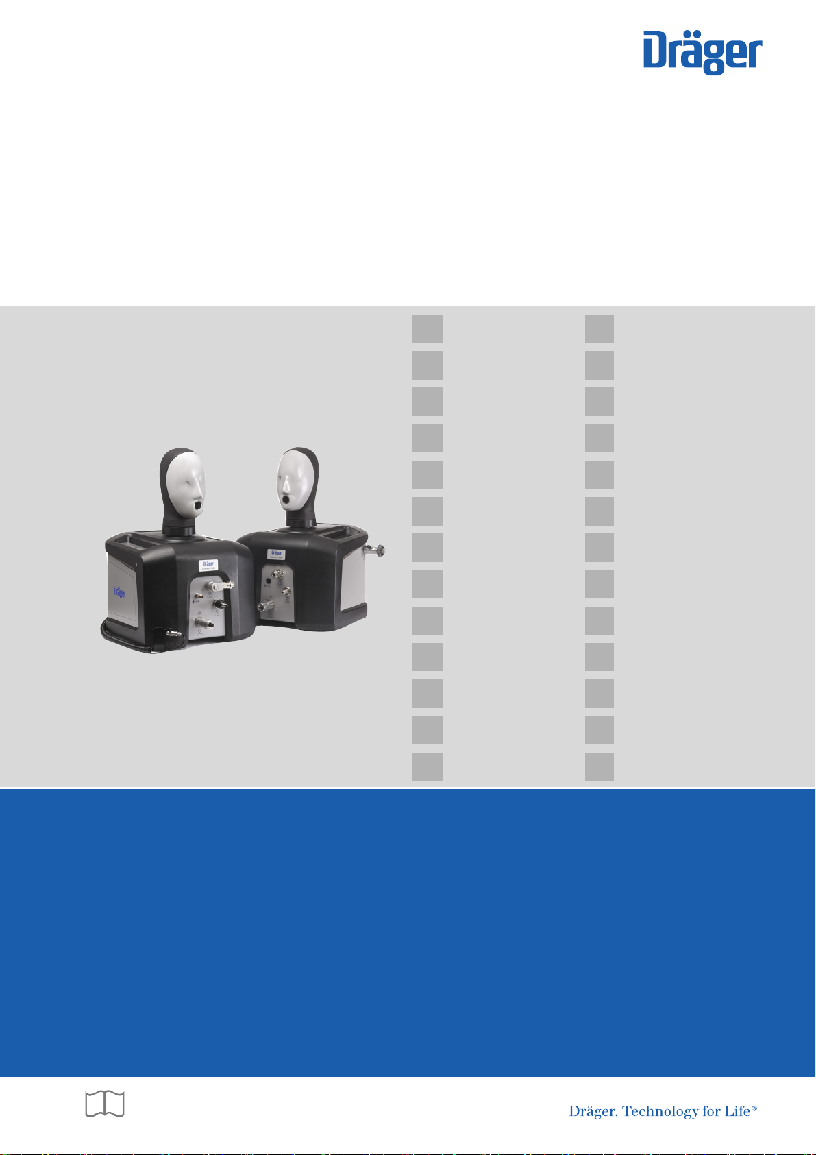
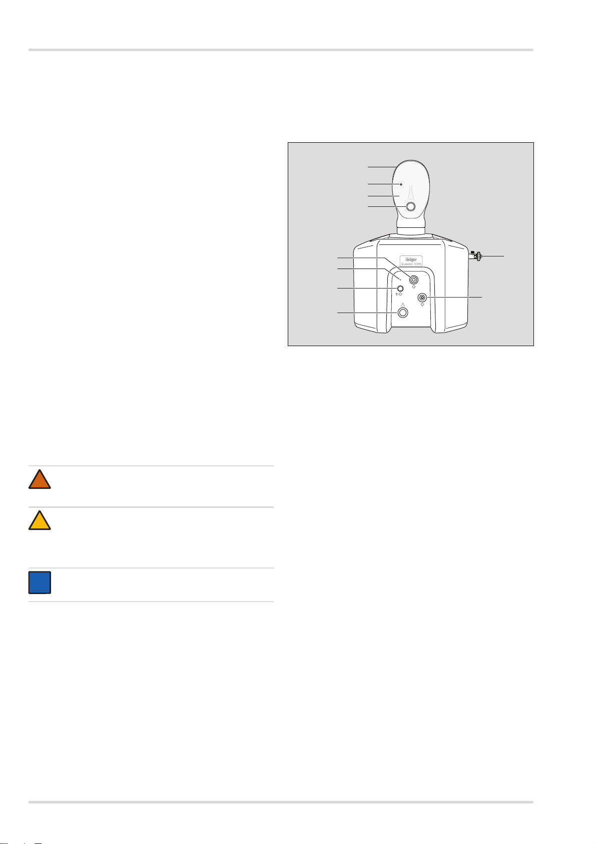
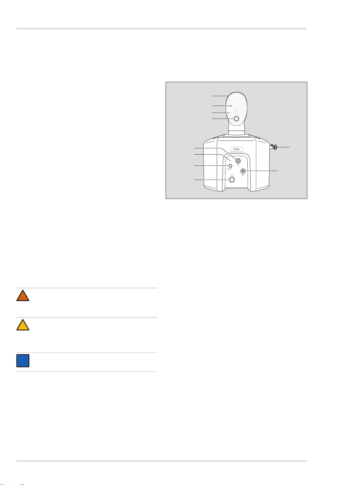
2.1.1 Dräger Quaestor 5000 (Ansicht von vorn)
1
2
3
4
5
6
7
9
8
1Prüfkopf
2 Messpunkt (im Auge)
3 Gelgesicht
4 Anschluss für Veratmungsadapter
5 Anschluss für Lungenautomat/Mitteldruck-Ausgang
6LED
7 Blindstopfen
8 Hochdruck-Ausgang
9 Mitteldruck-Eingang
10 Hochdruck-Eingang
10
00121868.eps
WARNUNG
Hinweis auf eine potenzielle Gefahrensituation.
Wenn diese nicht vermieden wird, können Tod oder
schwere Verletzungen eintreten.
VORSICHT
Hinweis auf eine potenzielle Gefahrensituation. Wenn
diese nicht vermieden wird, können Verletzungen oder
Schädigungen am Produkt oder der Umwelt eintreten.
Kann auch als Warnung vor unsachgemäßem Gebrauch verwendet werden.
HINWEIS
Zusätzliche Information zum Einsatz des Produkts.
4 Dräger Quaestor 5000/7000
Page 5

Beschreibung
02121868.eps
11
12
13
14
20
22
15
21
16
17
19
18
02221868.eps
25
26
27
23
24
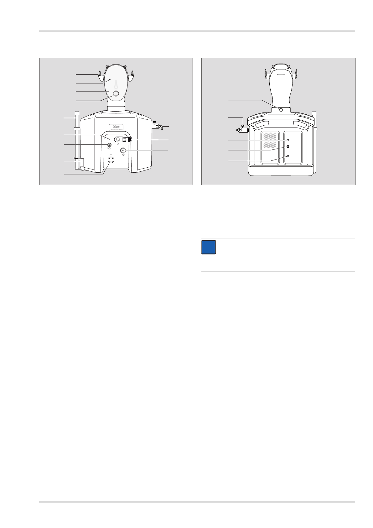
2.1.2 Dräger Quaestor 7000 (Ansicht von vorn)
11 Adapter für Masken/Helm-Kombinationen
12 Messpunkt (im Auge)
13 Gelgesicht
14 Anschluss für Veratmungsadapter
15 Pressluftatmer-Halter (optional, nur der untere Teil ist
dargestellt)
16 LED
17 Anschluss zum Füllen des Chemikalienschutzanzugs
18 Halter für Manometer oder Bodyguard
19 Hochdruck-Ausgang
20 Mitteldruck-Eingang
21 Anschluss für Lungenautomat/Mitteldruck-Ausgang
22 Hochdruck-Eingang
2.1.3 Beide Prüfgeräte (Ansicht von hinten)
23 Hebel zum Arretieren und Abnehmen des Prüfkopfs
24 Entlüftungsschraube
25 Mikrofon-Anschluss (nur Quaestor 7000)
26 USB-Anschluss für die Verbindung zum PC
27 Stromversorgung
HINWEIS
i
i
Um die Funktionssicherheit des Prüfgeräts zu gewährleisten, darf nur Zubehör von Dräger an die Ein- und
Ausgänge angeschlossen werden.
2.2 Funktionsbeschreibung
Mit dem Dräger Quaestor 5000 und dem Dräger
Quaestor 7000 kann die Dichtheit und Funktionsfähigkeit von
verschiedenen Atemschutzprodukten geprüft werden. Der
Dräger Quaestor 5000 ist ein teilautomatisches Prüfgerät, der
Dräger Quaestor 7000 arbeitet vollautomatisch.
Bei beiden Prüfgeräte ermöglicht eine künstliche Lunge die
Atemsimulation bei Veratmungsprüfungen. Der Prüfkopf kann
gedreht werden, sodass der Zugang zum Prüfkopf bei einer
Prüfung einfach ist.
Die Prüfgeräte werden über einen PC bedient. Die mitgelieferte Software gibt alle Prüfschritte vor und protokolliert die Prüfergebnisse. Die Prüfergebnisse können gespeichert und
gedruckt werden. Eine Terminüberwachung stellt sicher, dass
die Prüfintervalle eingehalten werden.
Dräger Quaestor 5000/7000 5
Page 6
Beschreibung
Folgendes Zubehör ist im Lieferumfang des Dräger
Quaestor 7000 enthalten:
Externes Mikrofon
Mit dem Mikrofon kann das Signal der akustischen
Warnpfeife beim Prüfen eines Pressluftatmers oder
Kreislauf-Atemschutzgeräts erfasst werden.
Halter für Manometer oder Bodyguard
Der Halter ist optional für den Dräger Quaestor 5000 erhältlich.
Folgendes Zubehör ist optional sowohl für den Dräger
Quaestor 5000 als auch für den Dräger Quaestor 7000 erhältlich:
200 bar-Option
Wenn das Prüfgerät mit einem Prüfdruck von 200 bar
arbeiten soll, muss die 200 bar-Option angeschlossen
werden. Außerdem darf am Hochdruck-Eingang nur ein
Druck von 200 bar anliegen. Dräger empfiehlt, am
Hochdruckeingang den Druckminderer R 57 584
anzuschließen.
Falls der Druck im Prüfgerät höher als 200 bar ist, strömt
die Luft ab, ohne das Atemschutzprodukt zu beschädigen.
Pressluftatmer-Halter
zum aufrechten Positionieren des Pressluftatmers
während der Prüfung
Adapter für Masken/Helm-Kombinationen
zum Befestigen einer Maske ohne Kopfbänderung auf dem
Prüfkopf
1
QSI
-Box
zur Schallisolierung der Restdruckwarnung von
Manometer oder Bodyguard
Veratmungsadapter
zur positiven Dichtprüfung gemäß vfdb 0804
Haube
für den Schutz des Prüfgeräts vor Staub und Wasser
am Pressluftatmer
Statischer Mitteldruck
Ansteigen des Mitteldrucks
Hochdruck-Dichtprüfung
Manometervergleich
Prüfung des Head-up Displays (manuell)
Ansprechdruck der akustischen Warneinrichtung
Veratmungsprüfung (Prüfung des dynamischen
2
Einatemwiderstands)
am Chemikalien-Schutzanzug
Dichtheit des Schutzanzugs
Dichtheit der Anzugventile
Chemikalienschutzanzüge können mit dem Dräger
Quaestor 7000 vollautomatisch geprüft werden. Mit dem
Dräger Quaestor 5000 können die Messungen über den
Messpunkt im Auge durchgeführt werden, der Schutzanzug
muss aber mit einer Druckluftpistole aufgeblasen werden.
Beide Prüfgeräte können um Module erweitert werden, mit
denen Kreislauf-Atemschutzgeräte und das Sicherheitsventil
von Druckminderern geprüft werden können. Der Dräger
Quaestor 7000 kann zusätzlich um ein Modul erweitert
werden, mit dem Tauchgeräte geprüft werden können.
Die Prüfungen erfolgen gemäß vfdb-Richtlinie 0804 und für die
Pressluftatmer zusätzlich gemäß EN 137.
2.4 Symbolerklärung
Gebrauchsanweisung beachten
Anschluss für Chemikalienschutzanzug
(nur Quaestor 7000)
2.3 Bestimmungsgemäße Verwendung
Mit der Basisvariante des Dräger Quaestor 5000/7000 können
Pressluftatmer, Druckluft-Schlauchgeräte und Vollmasken geprüft werden. Je nach Gerätevariante können folgende Prüfungen durchgeführt werden:
an der Vollmaske:
Dichtprüfung bei Überdruck
Dichtprüfung bei Unterdruck
Öffnungsdruck des Ausatemventils
Prüfung des Head-up Displays (manuell)
am Lungenautomat:
Dichtheit im Überdruck
Dichtheit im Unterdruck
Öffnungsdruck
Schaltdruck
Statischer Überdruck
Prüfung Dosierventil
Veratmungsprüfung (Prüfung des dynamischen
Einatemwiderstands)
1 QSI = Quaestor Sound Isolation
2 nur, wenn eine Pressluftatmerprüfung durchgeführt wird
2
Vorsicht! Hochdruck-Anschluss
Eingang
Ausgang
6 Dräger Quaestor 5000/7000
Page 7
Inbetriebnahme des Prüfgeräts
i
i
i
i
00621868.eps
3 Inbetriebnahme des Prüfgeräts
3.1 Hinweise zur Handhabung des
Prüfgeräts
Um sicheres und unfallfreies Arbeiten mit dem Prüfgerät zu gewährleisten, folgende Punkte beim Arbeiten mit dem Prüfgerät
beachten:
Das Prüfgerät darf nur mit dem mitgelieferten Netzteil an
die Stromversorgung angeschlossen werden.
Das Prüfgerät muss vor der Inbetriebnahme mit der
Tischbefestigung am Arbeitsplatz befestigt werden.
Das Prüfgerät unbedingt gegen das Eindringen von
Wasser oder Feuchtigkeit schützen. In das Innere des
Prüfgeräts darf keine Feuchtigkeit durch Leck- oder
Spritzwasser gelangen.
Das Gehäuse darf nur von geschultem Dräger-Personal
geöffnet werden.
Das Prüfgerät muss einmal jährlich an Dräger zur
Inspektion eingeschickt werden. Die mitgelieferte
Verpackung für den Versand aufbewahren.
3.2 Voraussetzungen für den Gebrauch
Die Bedienung der Prüf-Software setzt Kenntnisse in der
Handhabung eines PCs mit MS-Windows voraus.
Der PC, auf dem die Prüf-Software installiert werden soll,
muss folgende Mindestanforderungen erfüllen:
Prozessor: 1,6 GHz oder höher
Arbeitsspeicher: 2 GB oder größer
freier Festplattenplatz: >500 MB
Betriebssystem: Windows 7 oder Windows 8
1 freier USB-Anschluss
Die Auflösung des Monitors sollte auf 1024*768 eingestellt
sein.
3.3 Vor dem ersten Gebrauch
Bevor das Prüfgerät in Betrieb genommen werden kann, müssen folgende Schritte durchgeführt werden:
1. Prüf-Software auf dem PC installieren und Daten anlegen
(siehe Kap. 3.3.1 auf Seite 7).
2. Falls vorhanden, Zubehör am Prüfgerät montieren (siehe
Kap. 3.3.2 auf Seite 7).
3. Prüfgerät aufstellen (siehe Kap. 3.3.3 auf Seite 9).
3.3.1 Prüf-Software auf dem PC installieren und Daten
anlegen
3. Die Hinweise beachten, die bei der Installation angezeigt
werden.
4. Den PC neu starten und anmelden.
HINWEIS
Bei der Auslieferung der Prüf-Software stehen folgende Benutzer zur Verfügung:
Der Benutzer "Chief" mit dem Kennwort
"Createdata"
Der Benutzer "admin" mit dem Kennwort "admin"
Informationen zur Prüf-Software sind auf den HilfeSeiten enthalten.
5. Die gewünschten Gerätedaten mit den Prüfeinstellungen
vom USB-Stick importieren. Folgende Datensätze stehen
zur Verfügung:
für die Datenbank EU im Verzeichnis EU:
- mask_EU.zip (Gerätedaten für Vollmasken)
- LDV_EU.zip (Gerätedaten für Lungenautomaten)
- reducer_EU.zip (Gerätedaten für Druckminderer)
- SCBA_EU.zip (Gerätedaten für Pressluftatmer)
- BG4_EU.zip (Gerätedaten für Kreislaufatemschutzgeräte)
- CPS_EU.zip (Gerätedaten für Chemikalienschutzanzüge)
- SCUBA_EU.zip (Gerätedaten für Tauchgeräte)
- Saver_EU.zip (Gerätedaten für Saver PP)
- Colt-Micro-ASV_EU.zip (Gerätedaten für Colt/
Micro/ASV)
Für die Datenbank NAFTA im Verzeichnis US:
- mask_US.zip (Gerätedaten für Vollmasken)
- LDV_US.zip (Gerätedaten für Lungenautomaten)
- reducer_US.zip (Gerätedaten für Druckminderer)
- SCBA_US.zip (Gerätedaten für Pressluftatmer)
- BG4_US.zip (Gerätedaten für Kreislaufatemschutzgeräte)
- CPS_US.zip (Gerätedaten für Chemikalienschutzanzüge)
In der Prüf-Software ggf. weitere Benutzer sowie
Atemschutzprodukte, Kunden und Standorte anlegen
(siehe "Erste Schritte" in den Hilfeseiten).
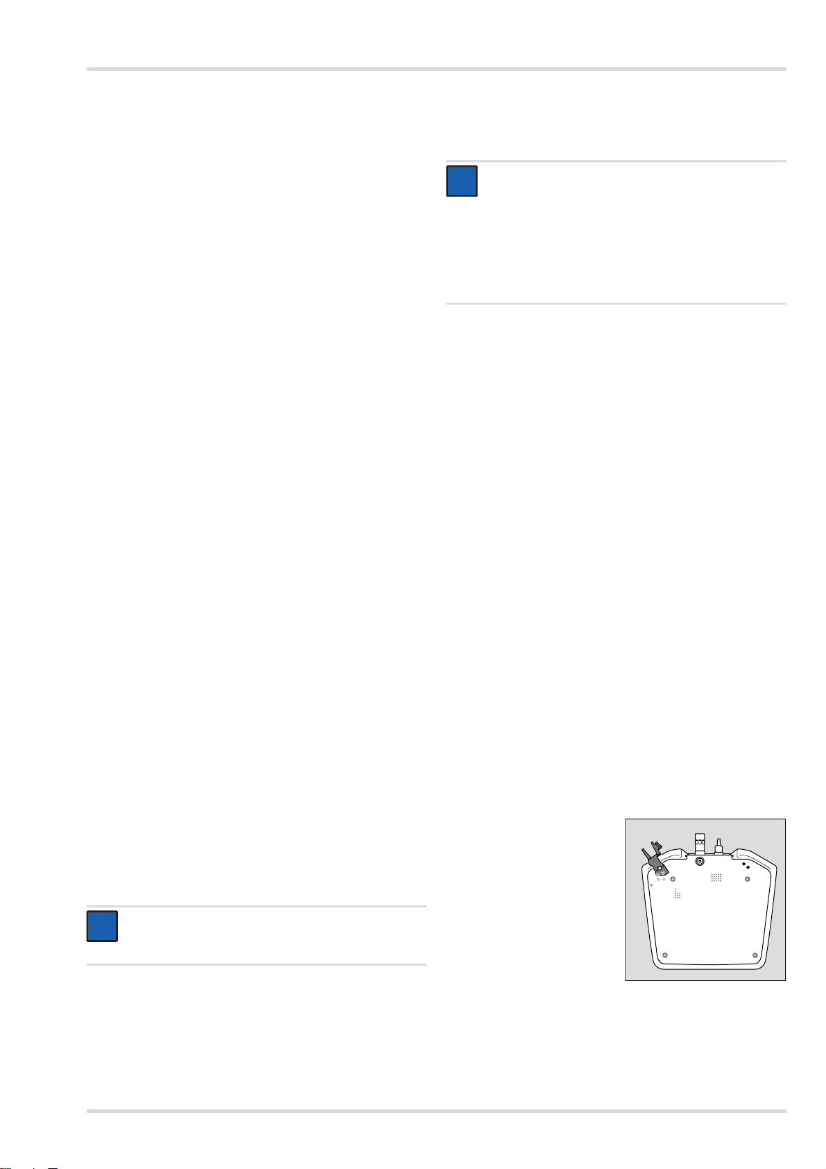
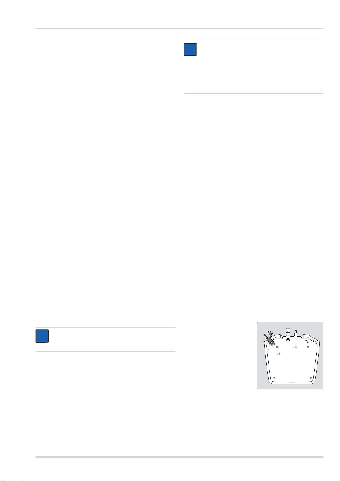
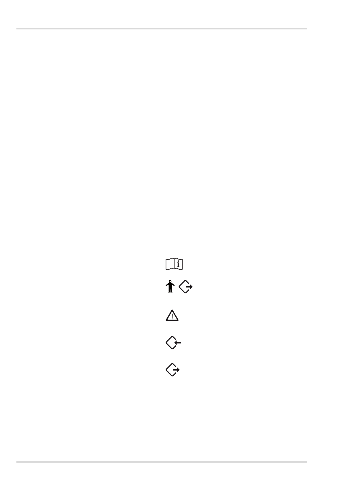
3.3.2 Zubehör montieren
Halter für Manometer oder Bodyguard montieren (nur
Dräger Quaestor 7000)
Den Halter rechts oder
links unter dem Prüfgerät
mit den 2 mitgelieferten
Schrauben festschrauben.
HINWEIS
Für die Installation muss der Benutzer AdministratorRechte für den PC haben.
1. Die Datei "Protector.exe" vom USB-Stick starten.
2. Den Anweisungen des Setup-Programms folgen.
Die erforderlichen Programmbestandteile werden in das
gewählte Verzeichnis installiert und im Startmenü wird ein
Eintrag erstellt.
Dräger Quaestor 5000/7000 7
Page 8
Inbetriebnahme des Prüfgeräts
i
i
00721868.eps
00821868.eps
i
i
00921868.eps
01021868.eps
12
01121868.eps
34
01221868.eps
5
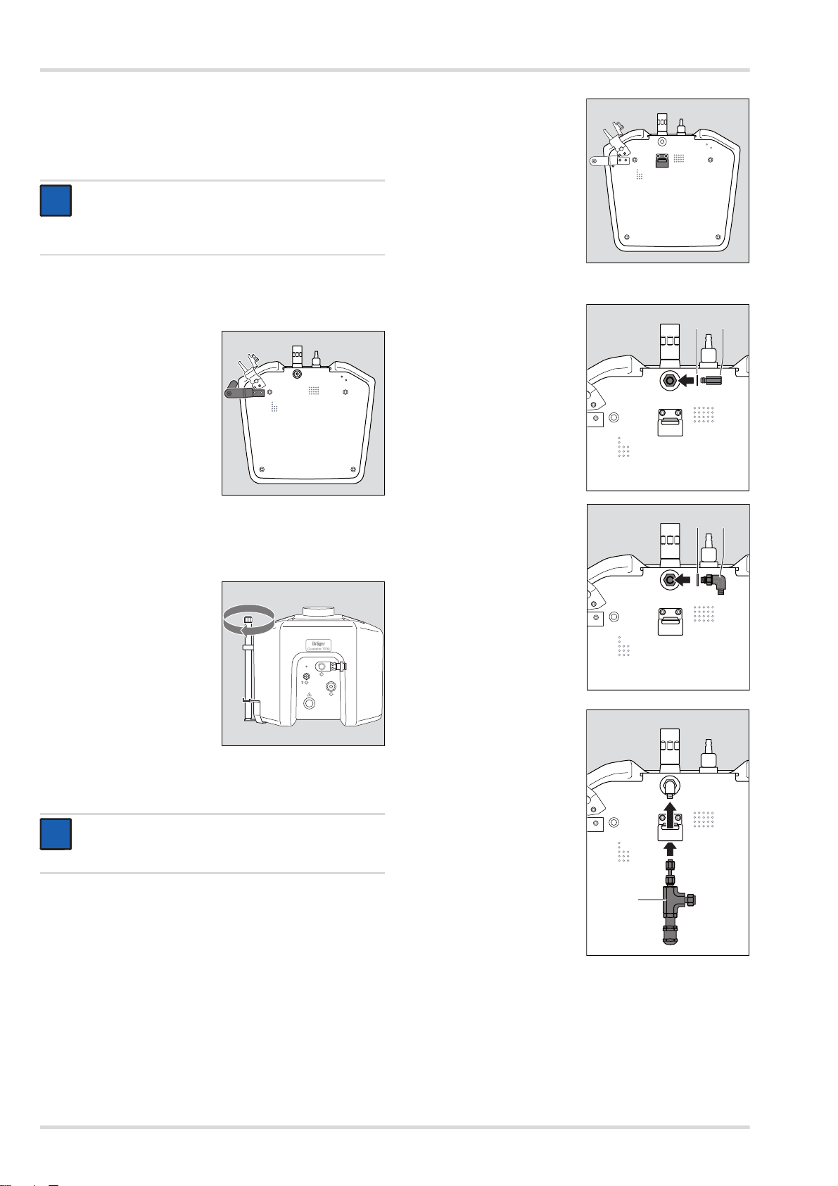
Mikrofon anschließen (nur Dräger Quaestor 7000)
1. Die rote Markierung am Mikrofon-Stecker und am
Prüfgerät aufeinander ausrichten und den MikrofonStecker in das Prüfgerät einstecken.
HINWEIS
Zum Lösen des Steckers die Buchse ca. 1 mm vom
Prüfgerät wegziehen. Dadurch wird die Verriegelung
gelöst und der Stecker kann vom Prüfgerät abgezogen
werden.
2. Das Mikrofon am Manometerhalter befestigen oder mit der
Klammer an einer beliebigen Stelle festklammern.
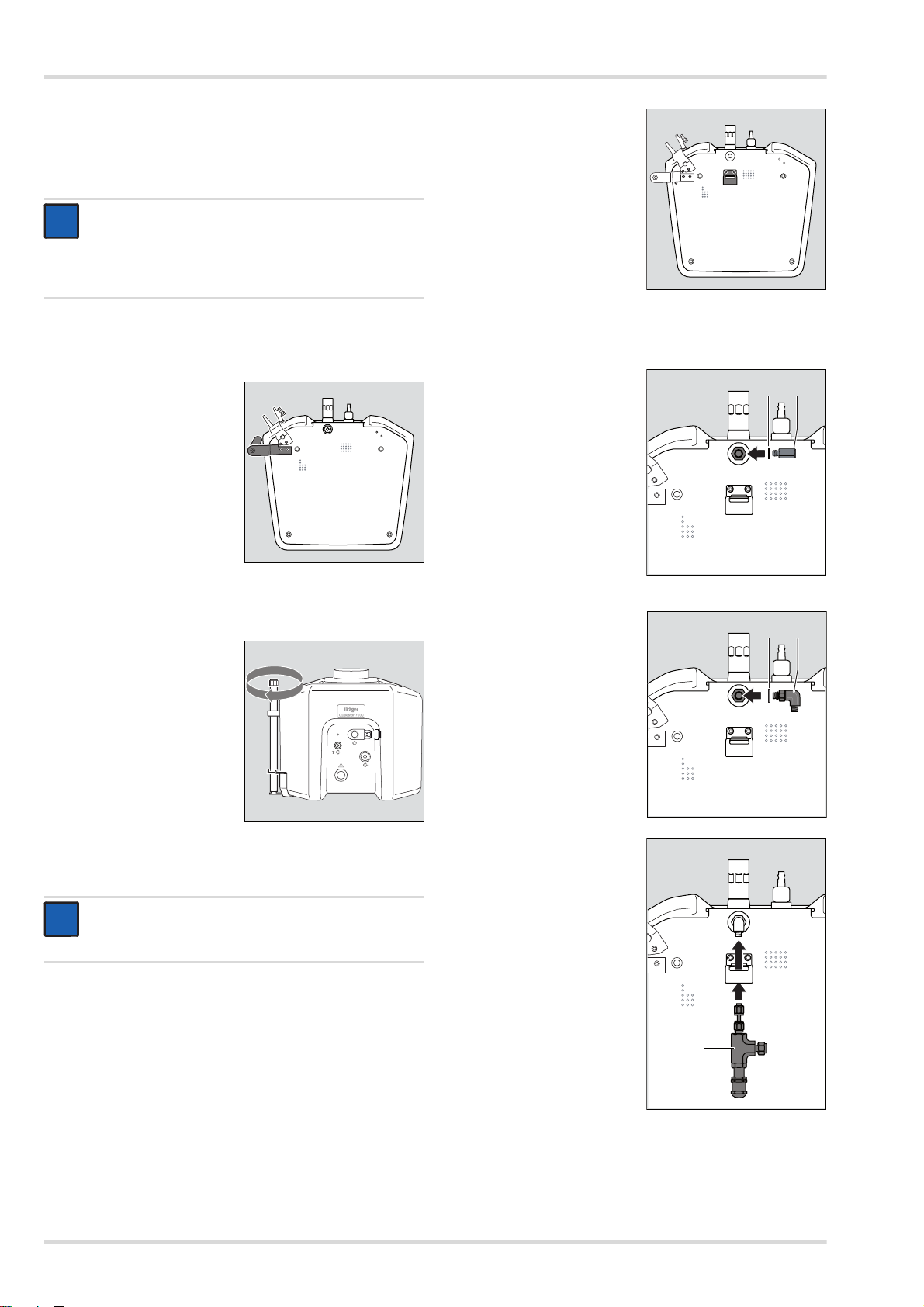
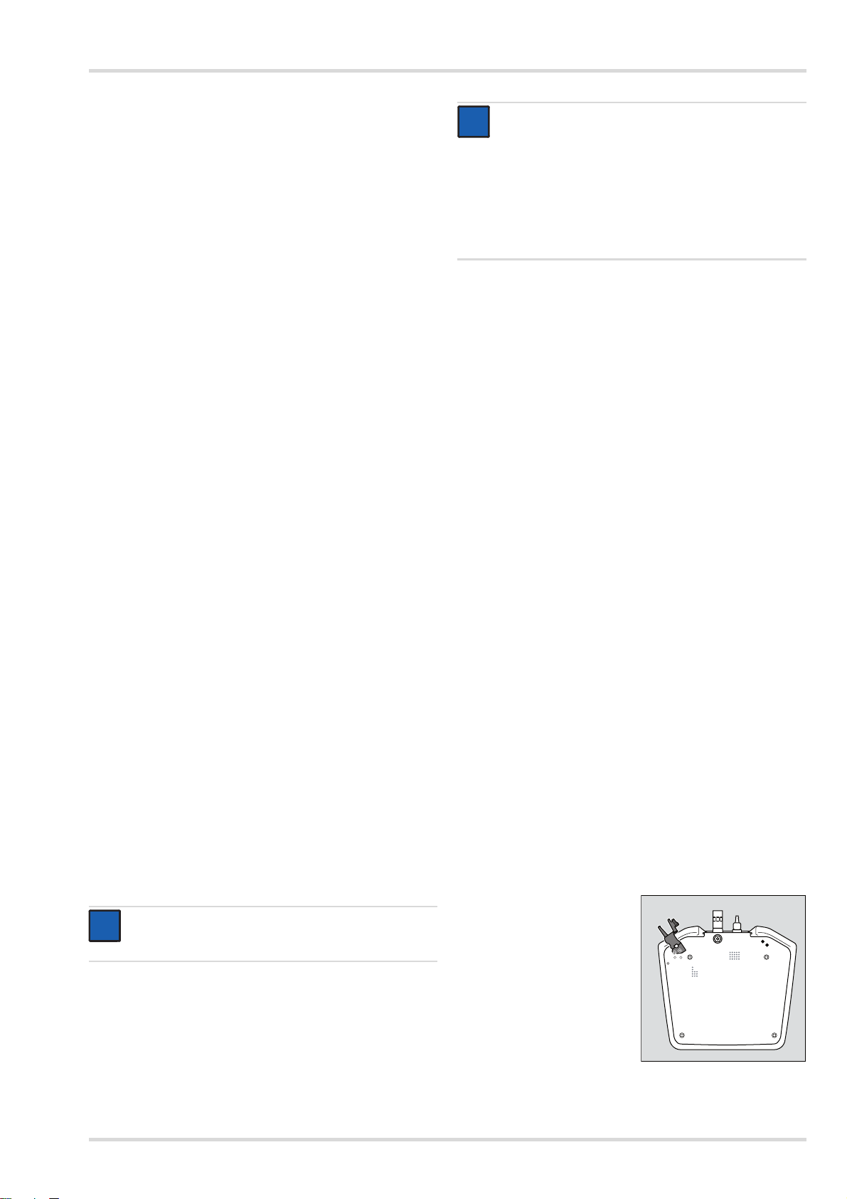
Pressluftatmer-Halter montieren
1. Den Pressluftatmer-Halter
links unter dem Prüfgerät
mit den 2 mitgelieferten
Schrauben festschrauben.
3. Die 2 Schrauben, mit
denen die 200 bar-Option
befestigt werden soll,
lösen.
4. Sicherungsringe auf die
Schrauben stecken. Die
Schrauben mit Loctite 221
benetzen und die
Halterung der 200 barOption an der gleichen
Stelle fixieren. Die
Schrauben nicht
festziehen.
5. Das Hochdruck-Anschlussstück von der 200 bar-Option
abschrauben.
6. Die Dichtung (1) auf das
HochdruckAnschlussstück (2)
aufsetzen.
7. Das HochdruckAnschlussstück mit einem
Steckschlüssel (19 mm)
im Prüfgerät
festschrauben.
2. Die Schelle des Pressluftatmer-Halters mit der Schraube
am Prüfgerät befestigen.
3. Die Rändelschraube
lösen.
4. Das Rohr einsetzen und
die Höhe des Tragarms so
einstellen, dass ein
Pressluftatmer an dem
Hochdruck-Ausgang des
Prüfgeräts angeschlossen
werden kann.
200 bar-Option montieren
HINWEIS
Bei der Montage die Sicherungsringe gut festhalten.
Die Sicherungsringe fallen leicht in das Prüfgerät.
1. Sicherstellen, dass das Prüfgerät stromlos ist.
2. Das Prüfgerät auf die Rückseite legen.
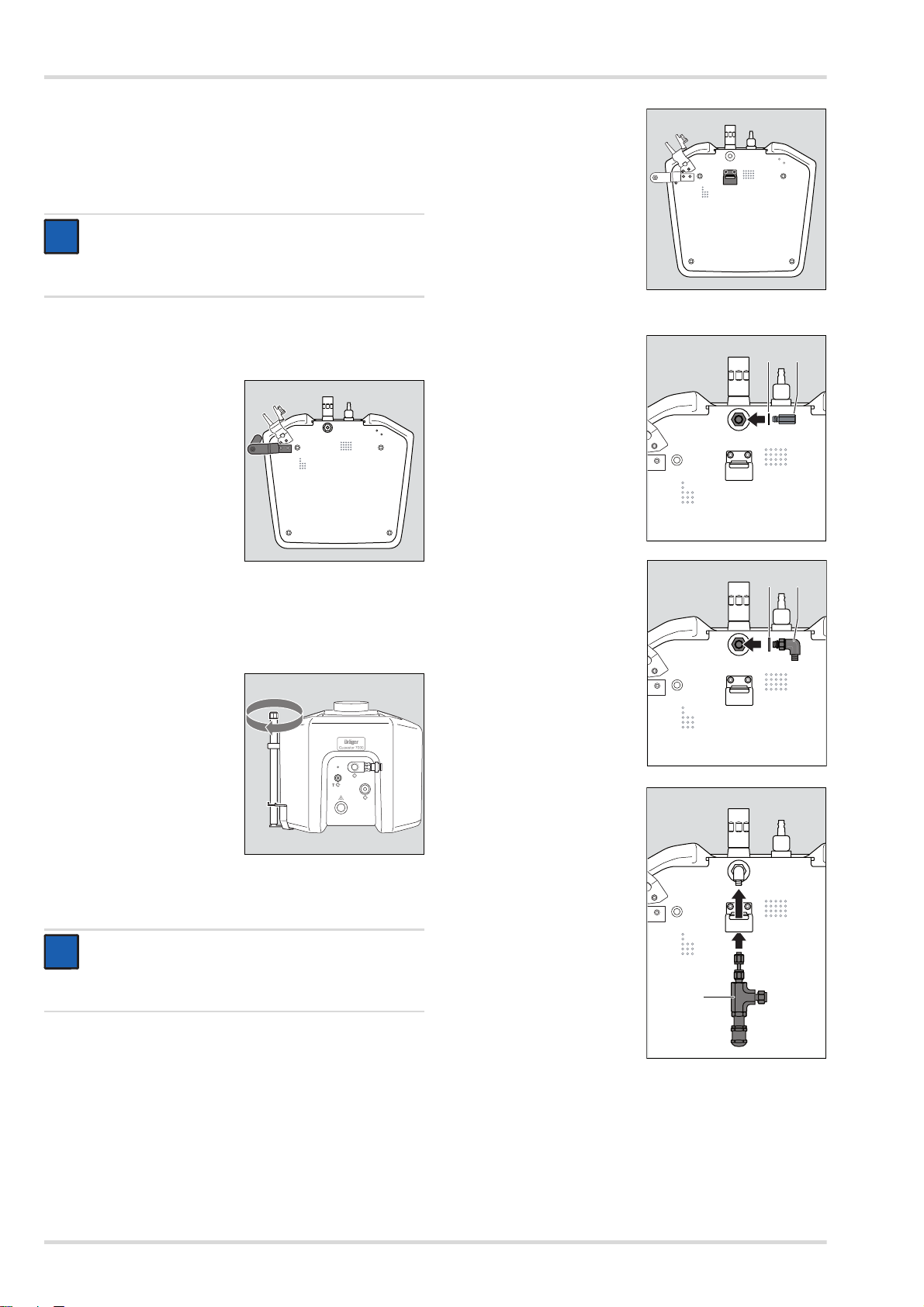
8. Die Scheibe (3) über den
O-Ring des L-Stücks (4)
streifen.
9. Das L-Stück mit der Hand
in das HochdruckAnschlussstück
schrauben. Der Ausgang
muss nach unten zeigen.
10. Die 200 bar-Baugruppe (5)
von unten durch die
Halterung schieben und
handfest in das L-Stück
einschrauben.
Darauf achten, dass die
Verbindung nicht
verkantet.
Ggf. das L-Stück
nachstellen, damit die
200 bar-Baugruppe auf
der gleichen Höhe wie der
Anschluss des L-Stücks
ist.
8 Dräger Quaestor 5000/7000
Page 9
Inbetriebnahme des Prüfgeräts
01321868.eps
6
7
i
i
i
i
02321868.eps
i
i
01521868.eps
12 cm
01621868.eps
1
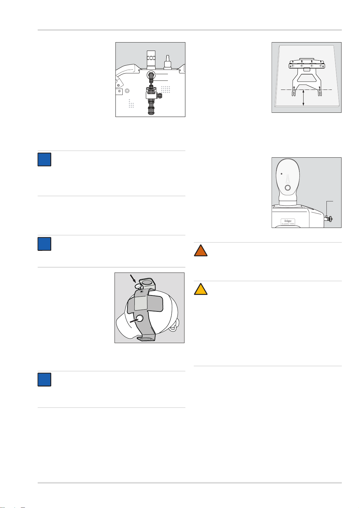
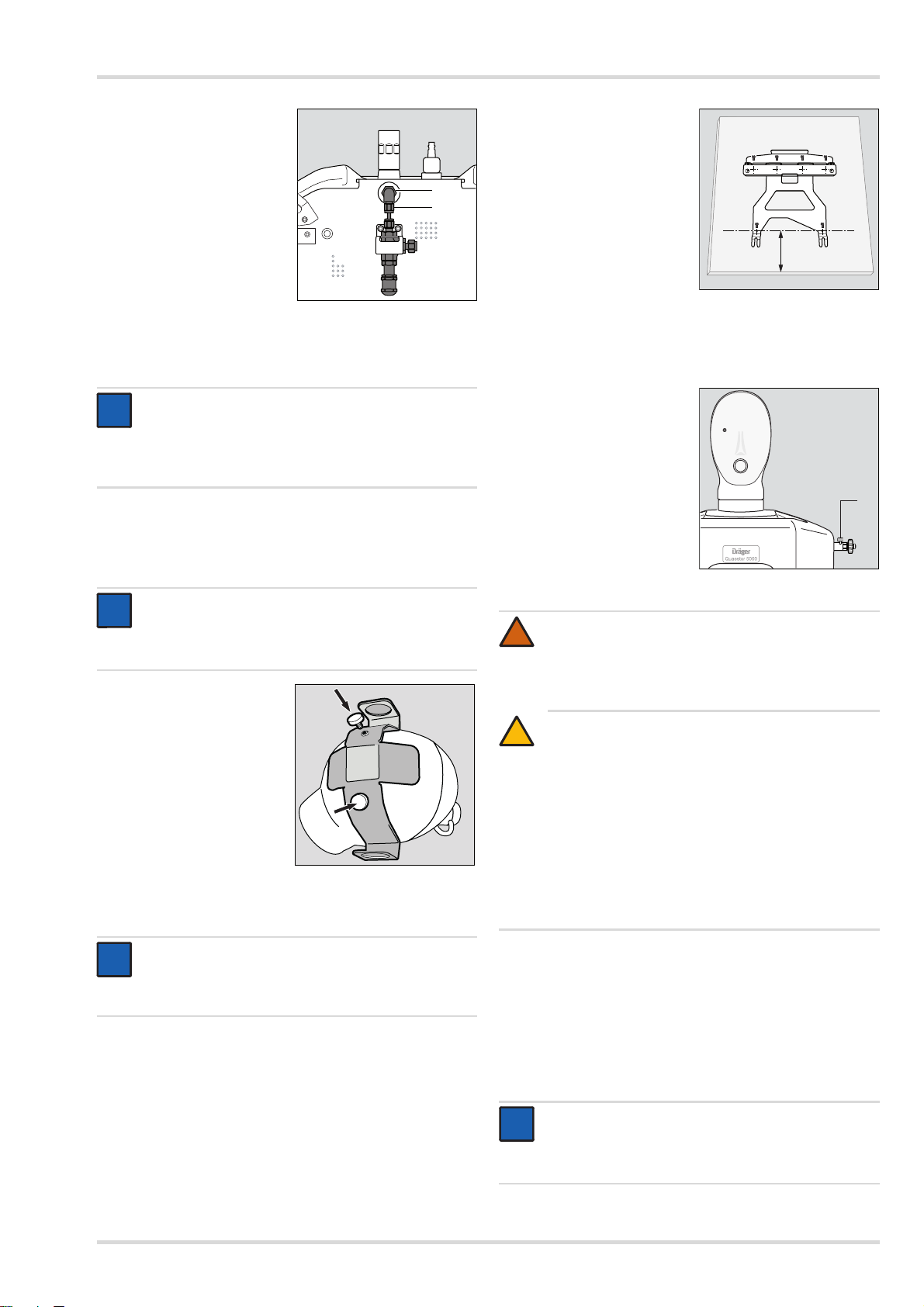
11. Die Schraubverbindung
Hochdruckausgang/LStück (6) mit einem
Sechskantschlüssel
(SW 14) festziehen.
12. Die Schraubverbindung LStück/200 bar-Baugruppe
(7) mit einem
Sechskantschlüssel
(SW 14) festziehen.
13. Alle Schraubverbindungen
an der 200 bar-Option
nachziehen.
14. Die 2 Schrauben der
Halterung festziehen.
HINWEIS
Dräger empfiehlt, außerdem den Druckminderer
R 57 584 an den Hochdruck-Eingang anzuschließen.
Damit kann sichergestellt werden, dass die Luft nur mit
einem Druck von 200 bar in das Prüfgerät eingespeist
wird.
Adapter für Masken/Helm-Kombinationen montieren
1. An den markierten Stellen des Prüfkopfs mit dem
mitgelieferten Bohrer jeweils ein Loch bohren.
1. Tischbefestigung parallel
zur Tischkante ausrichten.
Der Abstand zwischen
Tischkante und vorderen
Löchern der
Tischbefestigung muss
12 cm betragen.
2. Die Tischbefestigung mit
den mitgelieferten
Schrauben am Tisch
befestigen.
3. Das Prüfgerät hinten etwas anheben.
4. Die vorderen Füße des Prüfgeräts auf die Schlitze in der
Tischbefestigung ausrichten und das Prüfgerät nach
hinten in die Tischbefestigung schieben. Die hinteren Füße
müssen in die Tischbefestigung einrasten.
5. Sicherstellen, dass die
Entlüftungsschraube (1)
am Hochdruckeingang
geschlossen ist.
HINWEIS
Die "Schädeldecke" des Prüfkopfs ist ca. 5 mm dick,
der Prüfkopf ist innen hohl. Das Innere des Prüfkopfs
kann beim Bohren nicht beschädigt werden.
2. Den Adapter ausrichten
und mit den beiden
Schrauben fest
schrauben.
3.3.3 Prüfgerät aufstellen
HINWEIS
Prüfgerät auf einem Tisch oder einer Werkbank aufstellen.
Der PC sollte neben dem Prüfgerät platziert sein, damit dieser in Reichweite des Bedieners steht.
WARNUNG
!
Druckluft-Verrohrungen dürfen nur von geschultem
Personal angeschlossen werden.
Wird diese Warnung nicht beachtet, kann dies zu
schweren Körperverletzungen oder zum Tod führen.
VORSICHT
!
Für das Prüfgerät darf nur Atemluft gemäß EN 12 021
aus einem stationären Druckluft-Netz oder aus einer
Druckluftflasche verwendet werden. Wenn das Prüfgerät mit reinem Sauerstoff beaufschlagt wird, besteht
Brandgefahr.
Der maximal zulässige Hochdruck beträgt 300 bar
(4500 psi). Der maximal zulässige Mitteldruck beträgt
20 bar (58 psi). Bei höheren Drücken kann sowohl das
Prüfgerät als auch das Atemschutzprodukt beschädigt
werden.
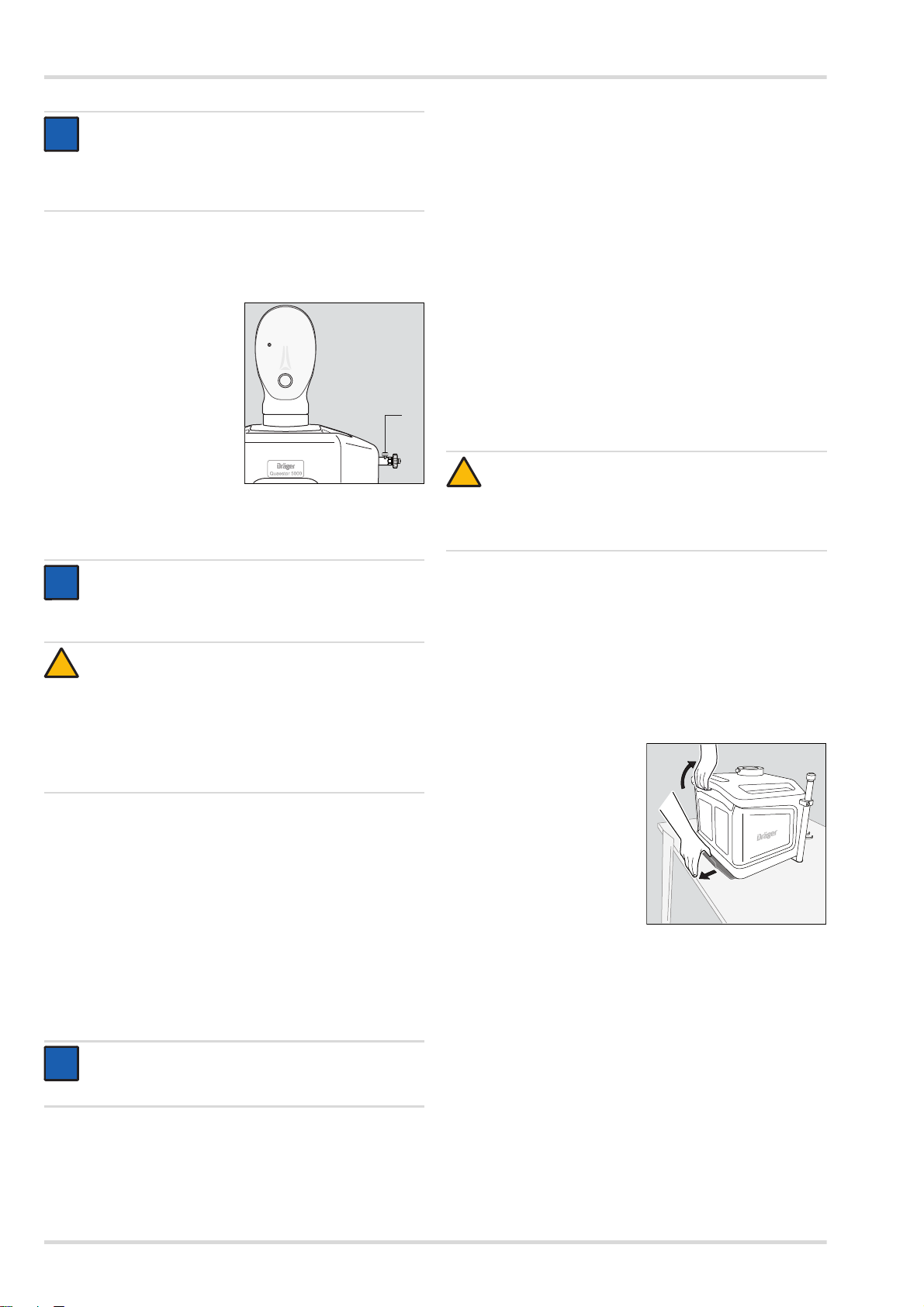
6. Druckluftflasche oder Druckluft-Verrohrung an den
Hochdruckeingang anschließen.
7. Prüfgerät mit dem USB-Kabel an den PC anschließen.
8. Prüfgerät an die Stromversorgung anschließen:
Die rote Markierung am Netzteil-Stecker und am Prüfgerät
aufeinander ausrichten und den Netzteil-Stecker in das
Prüfgerät einstecken.
Das Netzteil an die Stromversorgung anschließen.
Dräger Quaestor 5000/7000 9
Page 10
Inbetriebnahme des Prüfgeräts
i
i
01621868.eps
1
i
i
!
i
i
01721868.eps
1
2
HINWEIS
Zum Lösen des Steckers die Buchse ca. 1 mm vom
Prüfgerät wegziehen. Dadurch wird die Verriegelung
gelöst und der Stecker kann vom Prüfgerät abgezogen
werden.
3.4 Vorbereitungen vor jedem Gebrauch
3.4.1 Prüfgerät vorbereiten
1. Sicherstellen, dass die
Entlüftungsschraube (1)
am Hochdruckeingang
geschlossen ist.
2. Druckluftversorgung
öffnen.
3.4.2 Prüf-Software auf dem PC starten
Ein Nullabgleich aller Sensoren wird durchgeführt. Die
Anschlüsse müssen zu diesem Zeitpunkt drucklos sein.
Die künstliche Lunge wird positioniert.
Wenn eine Prüfung aufgerufen wird und Strom am Prüfgerät
anliegt, leuchtet die LED am Prüfgerät schwach. Wenn das
Prüfgerät mit dem PC kommuniziert, leuchtet die LED stark.
Wenn das Prüfgerät nicht funktionsfähig ist, wird eine Fehlermeldung am PC angezeigt.
3.5 Während des Gebrauchs
Der Prüfablauf wird in der Prüfsoftware beschrieben.
3.6 Nach dem Gebrauch
3.6.1 Arbeiten nach dem Prüfen
1. Vom System abmelden.
2. Die Druckluftversorgung schließen.
VORSICHT
!
Verletzungsgefahr beim Öffnen der Entlüftungsschraube!
Sicherstellen, dass die Entlüftungsschraube nicht auf
die Hände oder den Kopf gerichtet ist.
HINWEIS
Wenn eine Prüfung in der Prüf-Software aufgerufen
wird, wird das Prüfgerät automatisch eingeschaltet. Es
gibt keinen Ein-/Aus-Schalter am Prüfgerät.
VORSICHT
Kein Atemschutzprodukt an das Prüfgerät anschließen, bevor die Software aufgerufen wird. Beim Start
des Prüfgeräts muss das System drucklos sein, damit
sich die Drucksensoren gegen den aktuellen Umgebungsdruck abgleichen können. Sonst kann keine
Prüfung durchgeführt werden. In diesem Fall wird eine
Fehlermeldung angezeigt.
1. Die Prüf-Software aus dem Startmenü oder über die
Verknüpfung auf dem Desktop aufrufen.
Der Startbildschirm erscheint. Die Programmbestandteile
werden geladen. Wenn ein Systemfehler erkannt wird, wird
eine Fehlermeldung ausgegeben.
Ein Ladebalken mit Status-Information gibt Auskunft über
den Fortschritt des Startprozesses.
2. Wenn der Anmeldebildschirm erscheint, Namen und
Kennwort eingeben.
Nach dem Programmstart und der erfolgreichen Anmeldung
werden im Funktionsbereich die Registerkarten "Terminliste"
und "Prüfung" angezeigt.
3. Das Prüfgerät entlüften. Dazu die Entlüftungsschraube am
Hochdruckeingang öffnen. Die Druckluftflasche oder die
Verbindung zur stationären Druckluftversorgung vom
Prüfgerät demontieren.
4. Den Prüfaufbau demontieren.
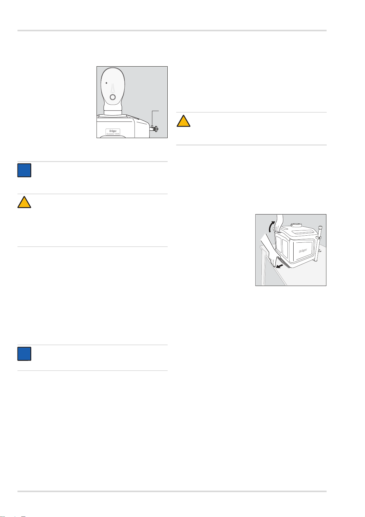
3.6.2 Prüfgerät demontieren
1. Um den Prüfkopf vom Prüfgerät abnehmen zu können, die
Verriegelung mit dem Hebel lösen und den Prüfkopf
abnehmen.
2. Den Riegel der
Tischbefestigung (1) nach
hinten ziehen.
3. Das Prüfgerät hinten am
Griff anheben (2) und nach
vorne aus der
Tischbefestigung ziehen.
HINWEIS
Dräger empfiehlt, vor Arbeiten mit dem Prüfgerät die
Software-Einstellungen zu überprüfen.
Wenn eine Prüfung in der Prüf-Software aufgerufen wird, wird
das Prüfgerät automatisch für den Gebrauch vorbereitet:
10 Dräger Quaestor 5000/7000
Page 11
Störungsbeseitigung
4 Störungsbeseitigung
Fehler Ursache Abhilfe
Das Prüfgerät
zischt beim Einschalten.
Die LED am Prüfgerät leuchtet
nicht, obwohl das
Prüfgerät an die
Stromversorgung
angeschlossen ist
und eine Prüfung
aufgerufen wurde.
Die LED am Netzteil leuchtet nicht.
Es ist keine Kommunikation mit der
PC-Software möglich (das Prüfgerät
wird nicht erkannt).
Prüfgerät defekt
Prüfgerät defekt
Netzteil defekt
USB-Kabel defekt
Prüfgerät defekt
Servicetechniker
verständigen
Servicetechniker
verständigen
Servicetechniker
verständigen
neues Kabel verwenden
Servicetechniker
verständigen
5 Wartung
5.1 Instandhaltungsintervalle
5.3 Wartungsarbeiten
5.3.1 Gelgesicht austauschen
1. Das alte Gelgesicht vom Prüfkopf abziehen.
2. Die Innenseite des neuen Gelgesichts mit Wasser
anfeuchten.
3. Um das neue Gelgesicht auf den Prüfkopf aufzusetzen,
zuerst das Auge mit dem Messpunkt aufsetzen und dann
das andere Auge am Prüfkopf positionieren. Das
Gelgesicht an den Prüfkopf anlegen.
4. Sicherstellen, dass der Rand des Gelgesichts rundherum
am Prüfkopf anliegt.
5. Dräger empfiehlt, eine Vollmaske auf dem Prüfkopf zu
montieren, bis die Feuchtigkeit zwischen Prüfkopf und
Gelgesicht verdunstet ist (z. B. über Nacht) und dann mit
der Prüfung zu beginnen.
6 Transport
Das Prüfgerät nur im ausgeschalteten Zustand transportieren.
Während des Transports in einem Fahrzeug darf das Prüfgerät nicht benutzt werden.
7 Lagerung
Das Prüfgerät trocken lagern. Direkte Sonneneinstrahlung und
Temperaturen über 60 °C vermeiden.
Durchzuführende Arbeiten
nach dem Gebrauch
jährlich
alle 6 Jahre
Gelgesicht prüfen X
Inspektion durchführen
Grundüberholung durchführen
1 Nur durch geschultes Fachpersonal
2 Um die Verfügbarkeit von Prüfgeräten sicherzustellen und somit
den Arbeitsfluss in Atemschutzwerkstätten zu unterstützen,
werden Grundüberholungen an Prüfgeräten seitens Dräger
vorgesehen. Aufgrund der unterschiedlichen Nutzung der
Prüfgeräte unterliegen Prüfgeräte zwar einem unterschiedlichen
Verschleiß, aber grundsätzlich empfiehlt Dräger eine
Grundüberholung nach spätestens sechs Jahren vornehmen zu
lassen.
1
2
X
X
5.2 Reinigung
Das Prüfgerät bei Bedarf mit einem feuchten Lederlappen
reinigen und trocknen.
8Entsorgung
Dieses Produkt darf nicht als Siedlungsabfall entsorgt
werden. Es ist daher mit dem nebenstehenden Symbol
gekennzeichnet.
Dräger nimmt dieses Produkt kostenlos zurück. Infor-
mationen dazu geben die nationalen Vertriebsorganisationen und Dräger.
Dräger Quaestor 5000/7000 11
Page 12

Technische Daten
9 Technische Daten 10 Bestellliste
Abmessungen mit Prüfkopf 50 x 55 x 65 cm
Gewicht (Vollausstattung,
incl. Prüfkopf)
Dräger Quaestor 5000 21 kg
Dräger Quaestor 7000 25 kg
Betriebstemperatur 0 °C ... +40 °C
Lagertemperatur -30 °C ... +60 °C
zulässige Feuchtigkeit 0 bis 90% rel. Feuchte,
nicht kondensierend
zulässiger Umgebungsdruck 800 ... 1200 hPa
Eingangsspannung 24 V DC
180 VA über externes
Netzteil (100-240 V,
50-60 Hz,
Bestellnummer R57466)
Druckluftversorgung Druckluftflasche oder
Edelstahl-Verrohrung für
300 bar
Genauigkeit der Drucksensoren Klasse <1.0 nach
DIN EN 837
Messbereiche
Hochdrucksensor 0 ... 350 bar
Mitteldrucksensor 0 ... 25 bar
Niederdrucksensor -40 ... +30 mbar
Niederdruck für Prüfungen
von Tauchgeräten
Atemfrequenz der
künstlichen Lunge
Hubvolumen max. 3,4 l
-70 ... +30 mbar
5 ... 40 Hübe/min
Benennung und Beschreibung Bestellnummer
Gelgesicht R57447
Schutzhaube für das Prüfgerät R57938
optionales Zubehör
QSI-Box R58382
Pressluftatmer-Halter R57420
Adapter für Masken/Helm-
Kombinationen
Halter für Manometer oder Bodyguard R58025
Hochdruck-Eingang, Standard, USA,
2216 psi
Hochdruck-Eingang, Schnellkupplung,
USA, 4500 psi
Hochdruck-Eingang, Schnellkupplung,
USA, 2216 psi
Hochdruck-Eingang, Schnellkupplung,
Deutschland, 300 bar
Hochdruck-Ausgang, 2216 psi R57953
2216 psi-Modul mit Ausgang R58368
2216 psi Ausgang R57593
200 bar-Option mit Ausgang R58367
Veratmungsadapter AG02535
Druckminderer R57584
Hochdruckschlauch (G5/8) R61899
Mitteldruck-Verlängerungsschlauch
(1 m)
Testkit für Saver/Colt/Micro/ASV R59337
Zubehör für CSA-Prüfung
Quaestor 5000, 2 Ventile am CSA R61886
Quaestor 5000, 1 Ventil am CSA R61887
Quaestor 7000, 2 Ventile am CSA R61888
Quaestor 7000, 1 Ventil am CSA R61889
R58116
R57620
R57618
R57617
R57619
R61898
12 Dräger Quaestor 5000/7000
Page 13

Contents
1 For your safety . . . . . . . . . . . . . . . . . . . . . . . . . . . .14
1.1 General safety instructions . . . . . . . . . . . . . . . . . . .14
1.2 Definitions of alert icons. . . . . . . . . . . . . . . . . . . . . .14
2 Description . . . . . . . . . . . . . . . . . . . . . . . . . . . . . . .14
2.1 Product overview . . . . . . . . . . . . . . . . . . . . . . . . . . .14
2.2 Functional description . . . . . . . . . . . . . . . . . . . . . . .15
2.3 Intended use . . . . . . . . . . . . . . . . . . . . . . . . . . . . . .16
2.4 Explanation of symbols . . . . . . . . . . . . . . . . . . . . . .16
3 Commissioning the test device . . . . . . . . . . . . . .17
3.1 Instructions on using the test device . . . . . . . . . . . .17
3.2 Preconditions for use . . . . . . . . . . . . . . . . . . . . . . . .17
3.3 Prior to first use . . . . . . . . . . . . . . . . . . . . . . . . . . . .17
3.4 Preparations before every use. . . . . . . . . . . . . . . . .20
3.5 During use . . . . . . . . . . . . . . . . . . . . . . . . . . . . . . . .20
3.6 After use. . . . . . . . . . . . . . . . . . . . . . . . . . . . . . . . . .20
4 Troubleshooting. . . . . . . . . . . . . . . . . . . . . . . . . . .21
5 Maintenance . . . . . . . . . . . . . . . . . . . . . . . . . . . . . .21
5.1 Maintenance intervals . . . . . . . . . . . . . . . . . . . . . . .21
5.2 Cleaning. . . . . . . . . . . . . . . . . . . . . . . . . . . . . . . . . .21
5.3 Maintenance work . . . . . . . . . . . . . . . . . . . . . . . . . .21
6 Transportation . . . . . . . . . . . . . . . . . . . . . . . . . . . .21
7 Storage . . . . . . . . . . . . . . . . . . . . . . . . . . . . . . . . . .21
8 Disposal . . . . . . . . . . . . . . . . . . . . . . . . . . . . . . . . .21
9 Technical data . . . . . . . . . . . . . . . . . . . . . . . . . . . .22
10 Order List . . . . . . . . . . . . . . . . . . . . . . . . . . . . . . . .22
Dräger Quaestor 5000/7000 13
Page 14
For your safety
!
!
i
i
1 For your safety
1.1 General safety instructions
Before using this product, carefully read the instructions for
use and the instructions for use of the associated products.
Strictly follow the instructions for use. The user must
understand and strictly observe the complete instructions.
Use the product only for the purposes specified in the
Intended use section of this document.
Do not dispose of the instructions for use. Ensure that they
are retained and appropriately used by the user.
Only fully trained and competent persons are permitted to
use this product.
Comply with all local and national rules and regulations
associated with this product.
Only trained and competent personnel are permitted to use
inspect, repair and service the product. Dräger
recommends a Dräger service contract for all maintenance
activities and that all repairs are carried out by Dräger.
Use only authentic Dräger spare parts and accessories.
Otherwise the proper functioning of the product may be
impaired.
Do not use a faulty or incomplete product. Do not modify
the product.
Notify Dräger in the event of any component faults or
failure.
1.2 Definitions of alert icons
The following alert icons are used in this document to identify
and highlight the associated alert texts and to emphasise
where users need to be particularly alert. The alert icons are
defined as follows:
WARNING
Indicates a potentially hazardous situation which, if not
avoided, could result in death or serious injury.
CAUTION
Indicates a potentially hazardous situation which, if not
avoided, could result in physical injury, or damage to
the product or environment. It may also be used as an
alert against unsafe practices.
NOTICE
Additional information on how to use the product.
2 Description
2.1 Product overview
2.1.1 Dräger Quaestor 5000 (viewed from front)
1
2
3
4
5
6
7
8
1 Test head
2 Measuring point (in the eye)
3Gel face
4 Connector for breathing adapter
5 Connector for lung demand valve/medium pressure outlet
6LED
7 Blind plug
8 High pressure outlet
9 Medium pressure inlet
10 High pressure inlet
10
9
00121868.eps
14 Dräger Quaestor 5000/7000
Page 15

Description
02121868.eps
11
12
13
14
20
22
15
21
16
17
19
18
02221868.eps
25
26
27
23
24
2.1.2 Dräger Quaestor 7000 (viewed from front)
11 Adapter for mask/helmet combinations
12 Measuring point (in the eye)
13 Gel face
14 Connector for breathing adapter
15 Compressed air breathing apparatus bracket (optional,
only the lower section is shown)
16 LED
17 Connector for filling the chemical protection suit
18 Bracket for gauge or Bodyguard
19 High pressure outlet
20 Medium pressure inlet
21 Connector for lung demand valve/medium pressure outlet
22 High pressure inlet
2.1.3 Both test devices (view from rear)
23 Lever for locking and removing the test head
24 Vent screw
25 Microphone connector (Quaestor 7000 only)
26 USB port for connection to a PC
27 Power supply
NOTICE
i
i
To ensure functional safety of the test device, it is only
permitted to connect accessories from Dräger to the
inputs and outputs.
2.2 Functional description
The Dräger Quaestor 5000 and Dräger Quaestor 7000 can be
used to perform leak testing and function testing of various
breathing safety products. The Dräger Quaestor 5000 is
a semi-automatic test device, the Dräger Quaestor 7000 is
fully automatic.
In both test devices, an artificial lung permits breathing
simulation with breathing tests. The test head can be rotated
so that the access to the test head is simple during a test.
The test devices are operated via a PC. The software included
with the device guides the user through the test steps and logs
the test results. The test results can be saved and printed.
Test date monitoring ensures that the inspection intervals are
observed.
Dräger Quaestor 5000/7000 15
Page 16

Description
The following accessories are included with the Dräger
Quaestor 7000:
External microphone
The microphone registers the signal of the acoustic whistle
when inspecting a compressed air breathing apparatus or
rebreathing apparatus.
Bracket for gauge or Bodyguard
The bracket is available as an option for the Dräger
Quaestor 5000.
The following accessories are available as options both for the
Dräger Quaestor 5000 and for the Dräger Quaestor 7000:
200 bar-Option
If the test device is to be operated at a test pressure of
200 bar, the 200 bar option must be connected. In addition,
it is only permitted for there to be a pressure of 200 bar on
the high pressure inlet. Dräger recommends connecting
pressure reducer R 57 584 to the high pressure inlet.
If the pressure in the test device is higher than 200 bar,
the air is released without damaging the respiratory
protective device.
Compressed air breathing apparatus bracket
for the upright positioning of the apparatus during the test
Adapter for mask/helmet combinations
for mounting the mask onto the test head without head
harness
1
QSI
-Box
for sound isolation of the residual pressure warning from
gauge or Bodyguard
Breathing adapter
for positive leak test conforming to vfdb 0804
Hood
to protect the test device against dust and water
2.3 Intended use
The basic version of the Dräger Quaestor 5000/7000 can be
used to test compressed air breathing apparatus, compressed
air hose breathing respirators and full face masks. Depending
on the device version, the tests can be performed on the
following components:
Full face mask:
Positive pressure leak test
Negative pressure leak test
Opening pressure of the exhalation valve
Head-up display test (manual)
On the lung demand valve:
Positive pressure leak test
Negative pressure leak test
Opening pressure
Switching pressure
Static positive pressure
Metering valve test
Breathing test (test of the dynamic breathing resistance)
2
On the compressed air breathing apparatus
Static medium pressure
Increase in the medium pressure
High pressure leak test
Comparative test for pressure gauge
Head-up display test (manual)
Response pressure of the acoustic warning device
Breathing test (test of the dynamic breathing
2
resistance)
On the chemical protection suit
Leak tightness of the chemical protection suit
Leak tightness of suit valves
Chemical protection suits can be tested in a fully automated
way using the Dräger Quaestor 7000. The Dräger
Quaestor 5000 can be used to perform the measurements via
the measuring point in the eye, however the protection suit
must be inflated using a compressed air gun.
Both test devices can be expanded using modules that can be
used to test closed-circuit breathing apparatus and the safety
valve on pressure reducers. The Dräger Quaestor 7000 can
also have a module added that can be used to test diving
apparatus.
The tests are conducted in accordance with the VFDB
Directive 0804 and for the compressed air breathing apparatus
also in accordance with EN 137.
2.4 Explanation of symbols
Strictly follow the instructions for use
Connection for chemical protection suit
(Quaestor 7000 only)
Caution! High pressure connection
Inlet
Outlet
1 QSI = Quaestor Sound Isolation
2 Only if a compressed air breathing apparatus test is being
performed
16 Dräger Quaestor 5000/7000
Page 17
Commissioning the test device
i
i
00621868.eps
3 Commissioning the test device
3.1 Instructions on using the test device
To ensure safe and accident-free work with the test device,
observe the following points when working with the test device:
The test device must only be connected to the power
supply using the power pack supplied.
Before commissioning, the test device must be attached to
the workstation using the table mount.
The test device must be protected against ingress of water
and moisture. Ensure that no moisture from splash water or
leaking water can ingress into the test device.
The housing may only be opened by trained Dräger personnel.
The test device must be sent to Dräger for inspection once
per year. Keep the packaging supplied for future shipping.
3.2 Preconditions for use
The use of the test software requires proficiency in MS Windows.
The PC on which the test software is to be installed must meet
the following minimum requirements:
Processor: 1.6 GHz or higher
RAM: 2 GB or more
Free disk space: >500 MB
Operating system: Windows 7 or Windows 8
1 free USB port
The monitor resolution should be set to 1024 x 768.
3.3 Prior to first use
Before the test device can be put into operation, the following
steps must be carried out:
1. Install the test software on the PC and create the data
(see chap. 3.3.1 on page 17).
2. If applicable, mount accessories onto the test device
(see chap. 3.3.2 on page 17).
3. Set up the test device (see chap. 3.3.3 on page 19).
NOTICE
i
i
On delivery, the test software includes the following
users:
The user "Chief" with the password "Createdata"
The user "admin" with the password "admin"
Information on the test software is also provided on the
help pages.
5. Import the required device data with the test settings from
the USB stick. The following data sets are available:
For the EU database in the EU directory:
- mask_EU.zip (apparatus data for full face masks)
- LDV_EU.zip (apparatus data for lung demand valves)
- reducer_EU.zip (apparatus data for pressure
reducers)
- SCBA_EU.zip (apparatus data for compressed air
breathing apparatus)
- BG4_EU.zip (apparatus data for closed-circuit
breathing apparatus)
- CPS_EU.zip (apparatus data for chemical
protection suits)
- SCUBA_EU.zip (apparatus data for diving equipment)
- Saver_EU.zip (apparatus data for Saver PP)
- Colt-Micro-ASV_EU.zip (apparatus data for Colt/
Micro/ASV)
For the NAFTA database in the US directory:
- mask_US.zip (apparatus data for full face masks)
- LDV_US.zip (apparatus data for lung demand valves)
- reducer_US.zip (apparatus data for pressure
reducers)
- SCBA_US.zip (apparatus data for compressed air
breathing apparatus)
- BG4_US.zip (apparatus data for closed-circuit
breathing apparatus)
- CPS_US.zip (apparatus data for chemical
protection suits)
In the test software, create additional users as well as
respiratory protection products, customers and locations
as required (see "First steps" in the help pages).
3.3.2 Fitting accessories
3.3.1 Installing the test software on the PC and creating
the data
NOTICE
For installation, the user must have administrator
rights for the PC.
Fitting brackets for gauge or Bodyguard (Dräger
Quaestor 7000 only)
Screw the holder on the
right and left underneath
the test device using the
2 bolts supplied.
1. Start "Protector.exe" from the USB flash drive.
2. Follow the instructions in the setup program.
The required program components will be installed in the
selected folder and an entry created in the start menu.
3. Observe the information displayed during installation.
4. Re-start the PC and log in.
Dräger Quaestor 5000/7000 17
Page 18
Commissioning the test device
i
i
00721868.eps
00821868.eps
i
i
00921868.eps
01021868.eps
12
01121868.eps
34
01221868.eps
5
Connecting the microphone (Dräger Quaestor 7000 only)
1. Align the red marking on the microphone plug and on the
test device with one another, and insert the microphone
plug into the test device.
NOTICE
To disconnect the plug, move the socket approx. 1 mm
away from the test device. This releases the lock, and
the plug can be removed from the test device.
2. Attach the microphone to the pressure gauge bracket or
attach it anywhere using the clip.
Fitting the compressed air breathing apparatus bracket
1. Screw the compressed air
breathing apparatus bracket
on the right and left
underneath the test device
using the 2 bolts supplied.
2. Fasten the clip on the compressed air breathing apparatus
bracket using the screw on the test device.
3. Unfasten the knurled
screw.
4. Insert the tube and adjust
the height of the support
arm so that compressed
air breathing apparatus
can be connected to the
high pressure outlet of the
test device.
Fitting the 200 bar option
NOTICE
Hold securely when fitting the locking rings. The locking
rings drop easily into the test device.
3. Unfasten the 2 screws
used to secure the 200 bar
option.
4. Place the locking rings onto
the screws. Place a small
amount of Loctite 221 on
the screws and fix the
200 bar option bracket at
the same position. Do not
tighten the screws.
5. Unscrew the highpressure connector from
the 200 bar option.
6. Place the seal (1) on the
high-pressure connector (2).
7. Screw the high-pressure
connector into the test
device using a socket
wrench (19 mm).
8. Move the washer (3) over
the O-ring on the L-piece
(4).
9. Screw the L-piece into the
high-pressure connector
by hand. The outlet must
point downwards.
10. Move the 200 bar module
(5) downwards through the
bracket and screw handtight into the L-piece.
Ensure that the connection
is not tilted.
Where necessary, adjust
the L-piece so that the
200 bar module is at the
same height as the L-piece
connection.
1. Ensure that the test device is without power.
2. Place the test device on its back.
18 Dräger Quaestor 5000/7000
Page 19
Commissioning the test device
01321868.eps
6
7
i
i
i
i
02321868.eps
i
i
01521868.eps
12 cm
01621868.eps
1
!
11. Tighten the high-pressure
outlet/L-piece screw
connection (6) using
a hexagon socket (wrench
size 14).
12. Tighten the L-piece/
200 bar module screw
connection (7) using a
hexagon socket (wrench
size 14).
13. Tighten all screw
connections on the
200 bar option.
14. Tighten the 2 screws on
the bracket.
NOTICE
Dräger also recommends connecting pressure
reducer R 57 584 to the high pressure input.
This makes it possible to ensure that the air is only fed
into the test device with a pressure of 200 bar.
Fitting the adapter for mask/helmet combinations
1. Use the drill supplied to drill a hole at each of the points
marked on the test head.
1. Align the table mount
parallel with the table edge.
The distance between the
table edge and the front
holes on the table mount
must be 12 cm.
2. Fasten the table mount to
the table using the screws
supplied.
3. Raise the test device
slightly at the back.
4. Align the front feet on the test device with the slots in the
table mount and move the test device backwards in the
table mount. The back feet must engage with the table
mount.
5. Ensure that the vent
screw (1) on the high
pressure inlet is closed.
NOTICE
The "top" of the test head is approx. 5 mm thick,
the test head is hollow inside. The interior of the test
head cannot be damaged by the drilling.
2. Align the adapter and
fasten with the two screws.
3.3.3 Setting up the test device
NOTICE
Position the test device on a table or workbench.
The PC should be positioned next to the test device so
that it is within the operator's reach.
WARNING
!
Compressed air pipework may only be connected by
trained personnel.
Failure to follow this warning could lead to death or serious injury.
CAUTION
For the test device, only breathing air according to
EN 12 021 from a stationary compressed air network
supply or from a compressed air cylinder may be used.
If the test device is inflated with oxygen, there is a risk
of fire.
The maximum permissible high pressure is 300 bar
(4500 psi). The maximum permissible medium
pressure is 20 bar (58 psi). At higher pressures,
both the test device and the breathing safety product
may be damaged.
6. Connect the compressed air pipework or the compressed
air hose to the high pressure inlet.
7. Connect the test device to the PC using the USB cable.
8. Connect the test device to the power supply:
Align the red marking on the power pack plug and on the
test device with one another, and insert the power pack
plug into the test device.
Connect the power supply unit to the mains.
NOTICE
i
i
To disconnect the plug, move the socket approx. 1 mm
away from the test device. This releases the lock,
and the plug can be removed from the test device.
Dräger Quaestor 5000/7000 19
Page 20
Commissioning the test device
01621868.eps
1
i
i
!
i
i
01721868.eps
1
2
3.4 Preparations before every use
3.4.1 Preparing the test device
1. Ensure that the vent
screw (1) on the high
pressure inlet is closed.
2. Open the compressed air
supply.
3.4.2 Starting the test software on the PC
NOTICE
When a test is called up on the test software, the test
device is switched on automatically. There is no on/off
switch on the test device.
CAUTION
Do not connect any respiratory protection product to the
test device before launching the software. When starting
the test device, the system must be depressurised so that
the pressure sensors can be synchronised with the
current ambient pressure. Otherwise, no tests can be
conducted. In this case, an error message is displayed.
1. Access the test software via the Start menu or the desktop
shortcut.
The startup screen appears. The program components are
loaded. If a system error is detected, this is indicated by an
error message.
A load bar with status information provides information on
the progress of the startup process.
2. When the login screen appears, enter the user name and
password.
After starting the program and successfully logging on,
the "Test due list" and "Test" tabs are displayed in the function
area.
3.5 During use
The test sequence is written to the test software.
3.6 After use
3.6.1 Work after testing
1. Log off from the system.
2. Close the compressed air supply.
CAUTION
!
Risk of injury when opening the vent screw!
Make sure that the vent screw is not pointed at the
hands or the head.
3. Vent the test device. To do this, open the vent screw on the
high pressure inlet. Remove the compressed air cylinder or
the connection on the stationary compressed air supply
from the test device.
4. Disassemble the test setup.
3.6.2 Disassembling the test device
1. To remove the test head from the test device, unfasten the
lock using the lever and remove the test head.
2. Pull the latch of the table
mount (1) backwards.
3. Lift the test device
backwards on the handle (2)
and pull out forwards from
the table mount.
NOTICE
Dräger recommends checking the software settings
before starting work with the test device.
When a test is called up on the test software, the test device is
switched on automatically for usage:
A zero adjustment of all sensors is performed.
The connections must be depressurised at that time.
The artificial lung is positioned.
If a test has been started and there is current being supplied to
the test device, the LED on the test device will be on weakly.
When the test device is communicating with the PC, the LED
will be on strongly. If the test device is not functional, an error
message is displayed on the PC.
20 Dräger Quaestor 5000/7000
Page 21
Troubleshooting
4 Troubleshooting
Fault Cause Remedy
The test device
makes a hissing
sound when it is
switched on.
The LED on the
test device does
not light up, even
though the test
device is
connected to
power supply and
a test has been
opened.
The LED on the
power supply unit
does not light up.
No communication
with the PC
software is possible
(the test device is
not recognised).
Test device faulty
Test device faulty
Power pack faulty
USB cable faulty Use a new cable
Test device faulty
Contact service
personnel
Contact service
personnel
Contact service
personnel
Contact service
personnel
5.3 Maintenance work
5.3.1 Replacing the gel face
1. Remove the old gel face from the test head.
2. Moisten the inside of the new gel face with water.
3. To place the new gel face onto the test head, first position
the eye with the measuring point on the test head, and then
position the other eye. Press the gel face against the
test head.
4. Ensure that the edge of the gel face is flush around the
entire test head.
5. Dräger recommends mounting a full face mask to the test
head until the moisture between the test head and the gel face
has evaporated (e. g. over night) and then commencing
the test.
6 Transport
Only transport the test device when it is switched off. The test
device may not be used during transport in a vehicle.
7 Storage
Store the test device in a dry place. Avoid direct sunlight and
temperatures above 60 °C.
5 Maintenance
5.1 Maintenance intervals
Work to do
After use
Annually
Every 6 years
Test the gel face X
Conduct inspection
Conduct a major overhaul
1 Only by trained specialist personnel.
2 To ensure the availability of test devices and thus support the
workflow in respiratory protection workshops, major overhauls on
test devices should be carried out as required by Dräger. Based on
the various uses for the test devices, test devices are subject to
different types of wear, but essentially Dräger recommends having
a major overhaul conducted at least every six years.
1
2
5.2 Cleaning
If required, clean the test device with a moist leather cloth
and dry it.
X
X
8 Disposal
This product is not permitted to be disposed of as
domestic waste. It is therefore marked with the
adjacent icon.
Dräger will accept the return of this product free
of charge. For information contact the national sales
organisations and Dräger.
Dräger Quaestor 5000/7000 21
Page 22

Technical data
9 Technical data 10 Order List
Dimensions with test head 50 x 55 x 65 cm
Weight (full equipment,
incl. test head)
Dräger Quaestor 5000 21 kg
Dräger Quaestor 7000 25 kg
Operating temperature 0 °C ... +40 °C
Storage temperature –30 °C ... +60 °C
Permissible humidity 0 to 90 % rel. humidity,
non-condensing
Permissible ambient pressure 800 ... 1200 hPa
Input voltage 24 V DC
180 VA via external
power pack (100-240 V,
50-60 Hz,
order number
Compressed air supply Compressed air cylinder
or stainless steel
pipework for 300 bar
Precision of the pressure sensors Class <1.0 conforming to
DIN EN 837
Measurement ranges
High pressure sensor 0 ... 350 bar
Medium pressure sensor 0 ... 25 bar
Low pressure sensor –40 ... +30 mbar
Low pressure for tests
on test devices
Breathing frequency of the
artificial lung
Stroke volume max. 3.4 l
–70 ... +30 mbar
5 ... 40 strokes/min
Name and description Order number
Gel face R57447
Safety hood for the test device R57938
Optional accessories
QSI box R58382
Compressed air breathing apparatus
bracket
Adapter for mask/helmet combinations R58116
Bracket for gauge or Bodyguard R58025
High pressure inlet, standard, USA,
2216 psi
High pressure inlet, quick-release
coupling, USA, 4500 psi
High pressure inlet, quick-release
coupling, USA, 2216 psi
High pressure inlet, quick-release
coupling, Germany, 300 bar
High pressure outlet, 2216 psi R57953
2216 psi module with output R58368
2216 psi output R57593
200 bar option with outlet R58367
Breathing adapter AG02535
Pressure reducer R57584
High-pressure hose (G5/8) R61899
Medium-pressure connection hose (1 m) R61898
Test kit for Saver/Colt/Micro/ASV R59337
Accessories for CPS test
Quaestor 5000, 2 valves on CPS R61886
Quaestor 5000, 1 valve on CPS R61887
Quaestor 7000, 2 valves on CPS R61888
Quaestor 7000, 1 valve on CPS R61889
R57420
R57620
R57618
R57617
R57619
22 Dräger Quaestor 5000/7000
Page 23

Sommaire
1 Pour votre sécurité . . . . . . . . . . . . . . . . . . . . . . . .24
1.1 Informations générales relatives à la sécurité . . . . .24
1.2 Signification des avertissements . . . . . . . . . . . . . . .24
2 Description . . . . . . . . . . . . . . . . . . . . . . . . . . . . . . .24
2.1 Aperçu du produit. . . . . . . . . . . . . . . . . . . . . . . . . . .24
2.2 Description du fonctionnement . . . . . . . . . . . . . . . .25
2.3 Utilisation conforme . . . . . . . . . . . . . . . . . . . . . . . . .26
2.4 Explication des symboles. . . . . . . . . . . . . . . . . . . . .26
3 Mise en service du dispositif de test . . . . . . . . . .27
3.1 Remarques concernant la manipulation du
dispositif de test . . . . . . . . . . . . . . . . . . . . . . . . . . . .27
3.2 Conditions d'utilisation . . . . . . . . . . . . . . . . . . . . . . .27
3.3 Avant la première utilisation. . . . . . . . . . . . . . . . . . .27
3.4 Préparatifs avant chaque utilisation . . . . . . . . . . . . .30
3.5 Pendant l'utilisation . . . . . . . . . . . . . . . . . . . . . . . . .30
3.6 Après l'utilisation . . . . . . . . . . . . . . . . . . . . . . . . . . .30
4 Élimination des pannes. . . . . . . . . . . . . . . . . . . . .31
5 Maintenance . . . . . . . . . . . . . . . . . . . . . . . . . . . . . .31
5.1 Intervalles de maintenance . . . . . . . . . . . . . . . . . . .31
5.2 Nettoyage. . . . . . . . . . . . . . . . . . . . . . . . . . . . . . . . .31
5.3 Travaux de maintenance . . . . . . . . . . . . . . . . . . . . .31
6 Transport . . . . . . . . . . . . . . . . . . . . . . . . . . . . . . . .31
7 Stockage . . . . . . . . . . . . . . . . . . . . . . . . . . . . . . . . .31
8 Élimination de l'appareil . . . . . . . . . . . . . . . . . . . .31
9 Caractéristiques techniques. . . . . . . . . . . . . . . . .32
10 Liste de commande . . . . . . . . . . . . . . . . . . . . . . . .32
Dräger Quaestor 5000/7000 23
Page 24
Pour votre sécurité
!
!
i
i
1 Pour votre sécurité
1.1 Informations générales relatives à la sécurité
Avant d'utiliser le produit, veuillez lire attentivement la notice
d'utilisation qui y est jointe et celle des produits rattachés.
Veuillez respecter étroitement les consignes de la notice
d'utilisation. L'utilisateur doit comprendre les instructions
dans leur totalité et respecter exactement la marche
à suivre. Le produit ne doit être utilisé que pour les
opérations stipulées dans le domaine d'application.
Ne pas jeter la notice d'utilisation. Vérifier que les utilisateurs
la conservent et l'emploient de manière appropriée.
Seul le personnel qualifié et ayant suivi une formation
spéciale, est autorisé à utiliser ce produit.
Respecter les directives nationales et locales concernant
ce produit.
Seul le personnel qualifié et ayant suivi une formation
spéciale, est autorisé à réparer et à effectuer l'entretien de
l'appareil. Dräger recommande de conclure un contrat de
service avec Dräger et de faire effectuer toutes les
réparations par Dräger.
Pour les réparations, n'utiliser que des pièces originales et
des accessoires Dräger. Sans quoi, le fonctionnement
correct de l'appareil pourrait être compromis.
Ne pas utiliser les produits erronés ou incomplets. Ne pas
modifier le produit.
Informer Dräger en cas de défaut ou de panne sur le
produit ou sur des parties du produit.
1.2 Signification des avertissements
Les avertissements suivants sont utilisés dans ce document
pour caractériser et mettre en relief les textes qui s'y
rapportent et demandent une attention accrue de la part de
l'utilisateur. Les avertissements sont définis comme suit :
2 Description
2.1 Aperçu du produit
2.1.1 Dräger Quaestor 5000 (vue frontale)
1
2
3
4
5
6
7
8
1 Tête de contrôle
2 Point de mesure (dans l'œil)
3 Visage en gel
4 Connexion pour adaptateur de débit respiratoire
5 Connexion pour soupape à la demande/sortie moyenne
pression
6LED
7 Bouchon borgne
8 Sortie haute pression
9 Entrée pression moyenne
10 Entrée haute pression
10
9
00121868.eps
AVERTISSEMENT
Signale une situation potentiellement dangereuse
qui, si elle n'est pas évitée, peut constituer un danger
de mort ou d'accident grave.
ATTE NTIO N
Signale une situation potentiellement dangereuse qui,
si elle n'est pas évitée, peut constituer un risque de
blessure ou endommager le produit ou l'environnement.
Peut avertir d'une utilisation non adéquate.
REMARQUE
Informations complémentaires sur l'utilisation du produit.
24 Dräger Quaestor 5000/7000
Page 25
Description
02121868.eps
11
12
13
14
20
22
15
21
16
17
19
18
02221868.eps
25
26
27
23
24
2.1.2 Dräger Quaestor 7000 (vue frontale)
11 Adaptateur pour combinaisons masque/casque
12 Point de mesure (dans l'œil)
13 Visage en gel
14 Connexion pour adaptateur de débit respiratoire
15 Support appareil respiratoire isolant (option, seule la partie
inférieure est représentée)
16 LED
17 Connexion pour le remplissage de la combinaison de
protection chimique
18 Support pour manomètre ou Bodyguard
19 Sortie haute pression
20 Entrée pression moyenne
21 Connexion pour soupape à la demande/sortie moyenne
pression
22 Entrée haute pression
2.1.3 Les deux appareils de test (vus de l'arrière)
23 Levier de blocage et de retrait de la tête de contrôle
24 Vis de purge
25 Connexion microphone (Quaestor 7000 uniquement)
26 Raccord USB pour la connexion au PC
27 Alimentation électrique
REMARQUE
i
i
Pour assurer le fonctionnement de l'appareil de
contrôle, ne connecter que des accessoires Dräger
aux entrées et aux sorties.
2.2 Description du fonctionnement
Les appareils Dräger Quaestor 5000 et Dräger Quaestor 7000
permettent de contrôler l'étanchéité et le fonctionnement de
différents produits de protection respiratoire. Dräger
Quaestor 5000 est un appareil de contrôle semi-automatique,
Dräger Quaestor 7000 fonctionne entièrement automatiquement.
Sur les deux appareils de contrôle, un poumon artificiel permet
la simulation respiratoire lors des contrôles respiratoires.
La tête de contrôle peut être tournée de sorte à pouvoir
y accéder facilement lors d'un test.
Les appareils de contrôle sont commandés via un PC.
Le logiciel fourni indique toutes les étapes de test et enregistre
les résultats. Ces derniers peuvent être enregistrés et
imprimés. Un système de surveillance temporel garantit le
respect des intervalles de test.
Dräger Quaestor 5000/7000 25
Page 26
Description
Les accessoires suivants sont compris dans la livraison de
Dräger Quaestor 7000 :
Microphone externe
Le microphone permet d'enregistrer le signal des avertisseurs
sonores lors du test d'un appareil respiratoire isolant ou d'un
appareil de protection respiratoire à circuit fermé.
Support pour manomètre ou Bodyguard
Ce support est disponible en option pour Dräger Quaestor 5000.
Les accessoires suivants sont disponibles en option pour
Dräger Quaestor 5000 et Dräger Quaestor 7000 :
200 Option 200 bar
Si le dispositif de test doit fonctionner avec une pression de
test de 200 bar, l'option 200 bar est nécessaire. Par ailleurs,
la valeur mesurée à l'entrée haute pression ne doit pas
dépasser 200 bar. Dräger recommande le raccordement d'un
détendeur R 57 584 à l'entrée haute pression.
Si la pression mesurée sur le dispositif de test est
supérieure à 200 bar, l'air sera évacuée sans endommager
l'appareil de protection respiratoire.
Fixation pour appareil respiratoire isolant
Pour positionner l'appareil respiratoire isolant à la verticale
lors du test
Adaptateur pour combinaisons masque/casque
Pour fixer un masque sur la tête de contrôle sans bandage
de tête
Boîte QSI
1
Pour l'insonorisation de l'alarme de pression de réserve du
manomètre ou du Bodyguard
Adaptateur respiratoire
Pour le contrôle d'étanchéité en pression positive selon
vfdb 0804
Capot
Pour protéger le dispositif de test de la poussière et de l'eau
Au niveau de l'appareil respiratoire isolant à bouteille d'air
comprimé
Moyenne pression statique
Augmentation de la moyenne pression
Contrôle d'étanchéité haute pression
Comparaison manomètre
Contrôle du Head-up display (manuel)
Pression de déclenchement du dispositif d'avertissement
2
sonore
Test de ventilation (contrôle de la résistance inspiratoire
en dynamique)
Au niveau de la combinaison de protection chimique
Étanchéité de la combinaison de protection
Étanchéité des soupapes de la combinaison
Les combinaisons de protection chimique peuvent être
contrôlées entièrement automatiquement à l'aide du Dräger
Quaestor 7000. Dräger Quaestor 5000 permet de réaliser des
mesures via le point de mesure dans l'œil, la combinaison de
protection devant cependant pour cela être gonflée à l'aide
d'un pistolet à air.
Des modules permettant de contrôler les appareils de
protection respiratoire à circuit fermé et la soupape de sûreté
des détendeurs peuvent être rajoutés aux appareils de test.
L'appareil Dräger Quaestor 7000 peut également être équipé
d'un module supplémentaire permettant de contrôler les
appareils destinés à la plongée.
Les tests sont réalisés selon la directive vfdb 0804 ainsi que
EN 137 pour les appareils respiratoires isolants.
2.4 Explication des symboles
Observer la notice d'utilisation
2.3 Utilisation conforme
La variante de base du Dräger Quaestor 5000/7000 permet de
contrôler les appareils respiratoires isolants, les appareils à
adduction d'air comprimé et les masques faciaux. Les contrôles
suivants peuvent être réalisés en fonction de la variante
d'appareil :
Au niveau du masque facial :
Contrôle d'étanchéité en surpression
Contrôle d'étanchéité en dépression
Pression d'ouverture de la soupape expiratoire
Contrôle du Head Up Display (manuel)
Au niveau de la soupape à la demande :
Étanchéité en surpression
Étanchéité en dépression
Pression d'ouverture
Pression de commutation
Surpression statique
Contrôle valve de débit
Test de ventilation (contrôle de la résistance inspiratoire
en dynamique)
1 QSI = Quaestor Sound Isolation
2 uniquement en cas de test de l'appareil respiratoire isolant
2
Raccord pour combinaison de protection
chimique
(réservé au Quaestor 7000)
Attention ! Raccord haute pression
Entrée
Sortie
26 Dräger Quaestor 5000/7000
Page 27
Mise en service du dispositif de test
i
i
i
i
00621868.eps
3 Mise en service du dispositif de test
3.1 Remarques concernant la manipulation
du dispositif de test
Pour garantir un fonctionnement sûr et sans perturbations du
dispositif de test, tenir compte des points suivants :
Le dispositif doit uniquement être raccordé à l'alimentation
électrique avec le bloc d'alimentation fourni.
Avant la mise en service, le dispositif de test doit être fixé
au poste de travail à l'aide de la fixation pour table.
Le dispositif de test doit impérativement être protégé des
infiltrations d'eau et d'humidité. L'humidité provenant de
projections ou de fuites d'eau ne doit en aucun cas parvenir
à l'intérieur de l'appareil.
Le boîtier peut uniquement être ouvert par le personnel
Dräger.
Le dispositif de test devra être expédié une fois par an à
Dräger en vue de son inspection. Conserver l'emballage
fourni pour le renvoi du dispositif.
3.2 Conditions d'utilisation
L'utilisation du logiciel de test suppose des connaissances quant
à la manipulation d'un ordinateur équipé de MS-Windows.
La configuration minimale de l'ordinateur sur lequel le logiciel
de test doit être installé est la suivante :
Processeur : 1,6 GHz ou plus
Mémoire de travail : 2 Go ou plus
Espace libre disque dur : >500 Mo
Système d'exploitation : Windows 7 ou Windows 8
1 port USB libre
La résolution du moniteur devrait être réglée sur 1024*768.
3.3 Avant la première utilisation
Effectuer les opérations suivantes avant de mettre le dispositif
en service :
1. Installer le logiciel de test sur le PC et créer les données
(voir le chap. 3.3.1 à la page 27).
2. Le cas échéant, installer les accessoires sur l'appareil de
test (voir le chap. 3.3.2 à la page 27).
3. Mettre le dispositif de test en place (voir le chap. 3.3.3 à la
page 29).
REMARQUE
À la livraison, le logiciel de test est prévu pour les
utilisateurs suivants :
L'utilisateur « Chief » disposant du mot de passe
« Createdata »
L'utilisateur «admin» disposant du mot de passe
«admin»
Les pages d'aide contiennent également des
informations sur le logiciel de test.
5. Importer les données du dispositif désirées avec les réglages
du contrôle qui se trouvent sur la clé USB. Les articles
suivants sont disponibles :
Pour la base de données EU du répertoire EU :
- mask_EU.zip (données de l'appareil pour les
masques complets)
- LDV_EU.zip (données des soupapes à la demande)
- reducer_EU.zip (données du détendeur)
- SCBA_EU.zip (données de l'appareil respiratoire
isolant)
- BG4_EU.zip (données de l'appareil de protection
respiratoire isolant à circuit fermé)
- CPS_EU.zip (données des combinaisons de
protection chimique)
- SCUBA_EU.zip (données des appareils de plongée)
- Saver_EU.zip (données de l'appareil pour le
Saver PP)
- Colt-Micro-ASV_EU.zip (données de l'appareil pour
les Colt/Micro/ASV)
Pour la base de données NAFTA, répertoire US :
- mask_US.zip (données de l'appareil pour les
masques complets)
- LDV_US.zip (données de l'appareil pour les
soupapes à la demande)
- reducer_US.zip (données de l'appareil pour les
détendeurs)
- SCBA_US.zip (données de l'appareil respiratoire
isolant)
- BG4_US.zip (données de l'appareil de protection
respiratoire isolant à circuit fermé)
- CPS_US.zip (données des combinaisons de
protection chimique)
Créer éventuellement des utilisateurs, des produits de
protection respiratoire, des clients et des sites
supplémentaires dans le logiciel de test (voir « Premiers
pas » des pages d'aide).
3.3.2 Monter les accessoires
3.3.1 Installer le logiciel de test sur le PC et créer des
données
REMARQUE
Pour l'installation, l'utilisateur doit disposer des droits
d'administrateur pour l'ordinateur.
Monter le support du manomètre ou du Bodyguard
(Dräger Quaestor 7000 uniquement)
Visser le support à droite
ou à gauche sous le
dispositif de test à l'aide
des 2 vis comprises dans
la fourniture.
1. Démarrer le fichier « Protector.exe » à partir de la clé USB.
2. Suivre les instructions du programme de configuration.
Les éléments du programme nécessaires sont installés
dans le répertoire choisi et une entrée est créée dans le
menu de démarrage.
3. Respecter les consignes affichées lors de l'installation.
4. Redémarrer le PC et se connecter.
Dräger Quaestor 5000/7000 27
Page 28
Mise en service du dispositif de test
i
i
00721868.eps
00821868.eps
i
i
00921868.eps
01021868.eps
12
01121868.eps
34
01221868.eps
5
Connecter le microphone (Dräger Quaestor 7000
uniquement)
1. Aligner le repère rouge de la fiche du microphone et du
dispositif de test et brancher la fiche du microphone dans
le dispositif.
REMARQUE
Pour débrancher la fiche, éloigner la douille d'1 mm de
l'appareil. Le verrouillage est alors débloqué et la fiche
peut être débranchée du dispositif.
2. Fixer le microphone sur le support du manomètre ou le
bloquer à l'endroit souhaité à l'aide de la bride.
Monter le support pour appareil respiratoire isolant
1. Visser le support pour
appareil respiratoire isolant
à gauche sous le dispositif
de test à l'aide des 2 vis
comprises dans la
fourniture.
3. Desserrer les 2 vis avec
lesquelles l'option 200 bar
doit être fixée.
4. Enficher les bagues de
sécurité sur les vis. Mettre
un peu de Loctite 221 sur
les vis et fixer le support de
l'option 200 bar au même
endroit. Ne pas serrer
les vis.
5. Dévisser la pièce de
raccordement haute
pression de l'option 200 bar.
6. Installer le joint (1) sur la
pièce de raccordement
haute pression (2).
7. Serrer la pièce de raccordement haute pression
dans le dispositif à l'aide
d'une clé à douille
(19 mm).
2. Fixer le collier du support pour l'appareil respiratoire isolant
à l'appareil de test avec la vis.
3. Desserrer la vis moletée.
4. Installer le tube et régler la
hauteur du bras support de
sorte qu'un appareil
respiratoire isolant soit
raccordé au niveau de la
sortie haute pression du
dispositif de test.
Monter l'option 200 bar
REMARQUE
Lors du montage, maintenir soigneusement les
bagues de sécurité. Ces dernières peuvent facilement
tomber dans l'appareil.
8. Glisser la rondelle (3) sur
le joint torique de la pièce
en L (4).
9. A la main, visser la pièce
en L dans la pièce de raccordement haute pression.
La sortie doit être dirigée
vers le bas.
10. Pousser le module
200 bar (5) par le bas dans
le support et serrer à la
main dans la pièce en L.
Veiller à ce que la liaison
ne soit pas en travers.
Ajuster la pièce en L si
nécessaire, de sorte que le
module 200 bar se trouve
à la même hauteur que le
raccord de la pièce en L.
1. Vérifier que le dispositif de test n'est pas sous tension.
2. Coucher le dispositif sur sa face arrière.
28 Dräger Quaestor 5000/7000
Page 29
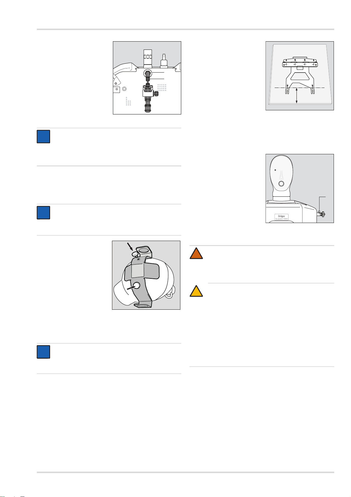
Mise en service du dispositif de test
01321868.eps
6
7
i
i
i
i
02321868.eps
i
i
01521868.eps
12 cm
01621868.eps
1
!
11. Serrer le vissage sortie
haute pression/pièce en
L (6) à l'aide d'une clé
à fourche (SW 14).
12. Serrer le vissage pièce
en L/élément 200 bar (7)
à l'aide d'une clé à fourche
(SW 14).
13. Serrer tous les
assemblages vissés au
niveau de l'option 200 bar.
14. Serrer les 2 vis du support.
REMARQUE
Dräger recommande également de raccorder le
détendeur R 57 584 à l'entrée haute pression. Ceci
permet de faire en sorte que l'air arrivant dans le
dispositif de test n'ait qu'une pression de 200 bar.
Monter l'adaptateur pour combinaison masque/casque
1. Percer un trou sur les emplacements marqués de la tête de
contrôle à l'aide du foret fourni.
REMARQUE
Le haut de la tête de contrôle a une épaisseur de 5 mm
env., la tête est creuse. L'intérieur de la tête ne peut
pas être endommagé lors du perçage.
1. Aligner la fixation de la
table parallèlement au
bord de la table. L'écart
entre le bord de la table et
les trous avant de la
fixation de la table doit être
de 12 cm.
2. Fixer la fixation de la table
à la table à l'aide des vis
fournies.
3. Soulevez légèrement la partie arrière du dispositif de test.
4. Aligner les pieds avant du dispositif sur les encoches de la
fixation de la table et le faire glisser vers l'arrière dans la
fixation de la table. Les pieds arrière doivent s'enclencher
dans la fixation de la table.
5. Veiller à ce que la vis de
purge (1) soit fermée au
niveau de l'entrée haute
pression.
2. Positionner l'adaptateur et
serrer avec les deux vis.
3.3.3 Installer le dispositif de test
REMARQUE
Poser le dispositif de test sur une table ou un établi.
Le PC devra se trouver à côté du dispositif afin d'être
bien accessible à l'utilisateur.
AVERTISSEMENT
Les tuyauteries d'air comprimé doivent être impérativement raccordées par un personnel formé.
Le non-respect de cet avertissement peut entraîner la
mort ou de graves blessures.
ATT ENTIO N
!
Pour le dispositif de test, seul de l'air respirable
conforme à EN 12 021 et provenant d'un réseau fixe
d'air comprimé ou d'une bouteille d'air comprimé peut
être utilisé. Risque d'incendie lorsque le dispositif de
test est alimenté avec de l'oxygène pur.
La haute pression maximale autorisée est de 300 bar
(4500 psi). La pression moyenne maximale autorisée
est de 20 bar (58 psi). En présence de pressions plus
élevées, le dispositif de test et l'équipement de
protection respiratoire risquent d'être endommagés.
6. Raccorder la bouteille d'air comprimé ou la tuyauterie de
l'air comprimé à l'entrée haute pression.
7. Raccorder le dispositif au PC à l'aide du câble USB.
8. Raccorder le dispositif de test à l'alimentation électrique :
Aligner le repère rouge de la fiche du bloc d'alimentation et
du dispositif et brancher la fiche du bloc d'alimentation
dans le dispositif de test.
Raccorder le bloc d'alimentation à l'alimentation électrique.
Dräger Quaestor 5000/7000 29
Page 30
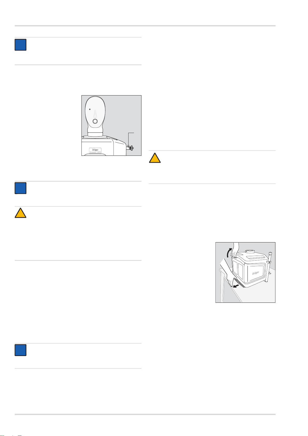
Mise en service du dispositif de test
i
i
01621868.eps
1
i
i
!
i
i
01721868.eps
1
2
REMARQUE
Pour débrancher la fiche, éloigner la douille d'1 mm de
l'appareil. Le verrouillage est alors débloqué et la fiche
peut être débranchée du dispositif.
3.4 Préparatifs avant chaque utilisation
3.4.1 Préparer le dispositif de test
1. Veiller à ce que la vis de
purge (1) soit fermée au
niveau de l'entrée haute
pression.
2. Ouvrir l'alimentation en air
comprimé.
3.4.2 Démarrer le logiciel de test sur le PC
REMARQUE
Lorsqu'un test est activé dans le logiciel de test,
le dispositif de test est automatiquement activé.
Le dispositif n'a pas de commutateur marche/arrêt.
ATTE NTIO N
Ne pas raccorder d'équipement de protection
respiratoire au dispositif avant d'activer le logiciel.
Lors du démarrage du dispositif de test, le système ne
doit pas être sous pression de sorte que les capteurs
de pression puissent s'équilibrer en fonction de la
pression ambiante existante. Dans le cas contraire,
aucun test ne peut être réalisé. Un message d'erreur
s'affiche alors.
1. Activer le logiciel de test depuis le menu de démarrage ou
à l'aide du raccourci sur le bureau.
L'écran de démarrage est affiché. Les éléments du
programme sont chargés. Dès qu'une erreur sur système
est identifié, ce dernier lance un message.
Une barre de chargement accompagnée du statut indique
la progression du démarrage.
2. Lorsque l'écran d'inscription s'affiche, entrer le nom et le
mot de passe.
Suite au démarrage du programme et à l'inscription réussie,
les onglets « Liste des dates de tests échus » et « Test »
s'affichent.
Un réglage du zéro de tous les capteurs est réalisé. Pour
cela, les raccords ne doivent pas être sous pression.
Le poumon artificiel est mis en place.
Si un test est activé et si le dispositif de test est alimenté en
courant, la LED du dispositif émet un signal faible. Lorsque le
dispositif de test communique avec le PC, la LED s'allume
avec une forte intensité. Si le dispositif de test n'est pas
opérationnel, un message d'erreur s'affiche sur le PC.
3.5 Pendant l'utilisation
Le déroulement du test est décrit dans le logiciel de test.
3.6 Après l'utilisation
3.6.1 Travaux à réaliser après le test
1. Se déconnecter du système.
2. Fermer l'alimentation en air comprimé.
ATTE NTIO N
!
Risque de blessure lors de l’ouverture de la vis d’évacuation d’air !
Veuillez vous assurer que la vis d’évacuation d’air
n’est pas dirigée vers les mains et la tête.
3. Purger le dispositif de test. Pour ce faire, ouvrir la vis de
purge à l'entrée haute pression. Démonter la bouteille d'air
comprimé ou le raccord à l'alimentation fixe en air
comprimé du dispositif de test.
4. Démonter l'assemblage pour le test.
3.6.2 Démonter le dispositif de test
1. Pour pouvoir retirer la tête de contrôle du dispositif de test,
débloquer le verrouillage avec le levier et retirer la tête.
2. Tirer le verrou de la fixation
de la table (1) vers l'arrière.
3. Soulever l'arrière du
dispositif de test à l'aide de
la poignée (2) et le tirer
vers l'avant hors de la
fixation de la table.
REMARQUE
Avant de commencer à travailler avec le dispositif
de test, Dräger recommande de contrôler les réglages
du logiciel.
Lorsqu'un contrôle est activé dans le logiciel de test, l'appareil de
contrôle est automatiquement préparé en vue de son utilisation.
30 Dräger Quaestor 5000/7000
Page 31

Élimination des pannes
4 Élimination des pannes
Erreur Cause Solution
Le dispositif de test
grésille lors de la
connexion.
La LED du
dispositif de test ne
s'allume pas bien
que ce dernier soit
alimenté en
courant et qu'un
test ait été activé.
La LED du bloc
d'alimentation ne
s'affiche pas.
Aucune
communication
possible avec le
logiciel PC
(le dispositif de
test n'est pas
reconnu).
Dispositif de test
défectueux
Dispositif de test
défectueux
Bloc d'alimentation
défectueux
Câble USB
défectueux
Dispositif de test
défectueux
Contacter le
technicien de
service
Contacter le
technicien de
service
Contacter le
technicien de
service
Utiliser un
nouveau câble
Contacter le
technicien de
service
5 Maintenance
5.3 Travaux de maintenance
5.3.1 Remplacer le visage en gel
1. Retirer l'ancien visage en gel de la tête de contrôle.
2. Humidifier l'intérieur du nouveau visage en gel avec de l'eau.
3. Pour installer le nouveau visage en gel sur la tête de
contrôle, placer d'abord l'œil avec le point de mesure puis
l'autre œil sur la tête de contrôle. Installer ensuite le visage
en gel sur la tête de contrôle.
4. Vérifier que le bord du visage en gel repose bien sur la tête
de contrôle.
5. Dräger conseille de monter un masque complet sur la tête
de contrôle jusqu'à ce que l'humidité entre la tête et le
visage en gel se soit évaporée (pendant la nuit p. ex.) et ne
commencer le test qu'ensuite.
6 Transport
Ne transporter le dispositif de test que lorsqu'il est à l'arrêt.
Le dispositif de test ne doit pas être utilisé pendant le transport
dans un véhicule.
7 Stockage
Stocker le de test dans un endroit sec. Eviter l'ensoleillement
direct et les températures supérieures à 60 °C.
5.1 Intervalles de maintenance
Opérations à effectuer
Après l'utilisation
Une fois par an
Tous les 6ans
Contrôler le visage en gel X
Effectuer une inspection
Effectuer une révision générale
1 Réservé au personnel muni de la formation adéquate.
2 Pour assurer la disponibilité des dispositifs et donc soutenir le
travail des ateliers de protection respiratoire, Dräger se chargera
des révisions générales des dispositifs de test. En raison des
diverses utilisations, les dispositifs de test s'usent différemment.
Néanmoins, Dräger recommande d'effectuer une révision
générale au moins tous les six ans.
1
2
X
X
5.2 Nettoyage
Si cela est nécessaire, nettoyer le dispositif de test avec un
chiffon en cuir humide puis sécher.
8 Élimination de l'appareil
Il est interdit d'éliminer le produit avec les déchets
domestiques. C'est pourquoi, il comprend le symbole
suivant.
Dräger reprend gratuitement ce produit. Pour de
plus amples informations à ce sujet, consulter les
distributeurs nationaux et Dräger.
Dräger Quaestor 5000/7000 31
Page 32

Caractéristiques techniques
9 Caractéristiques techniques 10 Liste de commande
Dimensions avec tête de contrôle 50 x 55 x 65 cm
Poids (équipement complet,
avec. tête de contrôle)
Dräger Quaestor 5000 21 kg
Dräger Quaestor 7000 25 kg
Température de service 0 °C ... +40 °C
Température de stockage –30 °C ... +60 °C
Humidité autorisée 0 à 90 % HR, sans
condensation
Pression ambiante autorisée 800 ... 1200 hPa
Tension d'entrée 24 V CC
180 VA via bloc
d'alimentation externe
(100-240 V,
50-60 Hz,
numéro de commande
R57466)
Alimentation air comprimé Bouteille d'air comprimé
ou tuyauterie en acier
spécial pour 300 bar
Précision des capteurs de
pression
Plages de mesure
Capteur haute pression 0 ... 350 mbar
Capteur de pression moyenne 0 ... 25 mbar
Capteur de basse pression –40 ... +30 mbar
Basse pression pour tests des
appareils de plongée
Fréquence respiratoire du
poumon artificiel
Volume par course max. 3,4 l
Classe <1.0 selon
DIN EN 837
–70 ... +30 mbar
5 ... 40 courses/min
Désignation et description
Visage en gel R57447
Capot de protection pour dispositif
de test
Accessoires en option
Boîtier QSI R58382
Support pour appareil respiratoire isolant R57420
Adaptateur pour combinaisons
masque/casque
Support pour manomètre ou Bodyguard R58025
Entrée haute pression, standard, USA,
2216 psi
Entrée haute pression, raccord rapide,
USA, 4500 psi
Entrée haute pression, raccord rapide,
USA, 2216 psi
Entrée haute pression, raccord rapide,
Allemagne, 300 bar
Sortie haute pression, 2216 psi R57953
2216 Module psi avec sortie R58368
2216 psi en sortie R57593
200Option 200 bar avec sortie R58367
Adaptateur de débit respiratoire AG02535
Détendeur R57584
Tuyau haute pression (G5/8) R61899
Rallonge à pression moyenne (1 m) R61898
Kit de test pour Saver/Colt/Micro/ASV R59337
Accessoire pour test VPC
Quaestor 5000, 2 soupapes sur
combinaison de protection chimique
Quaestor 5000, 1 soupape sur
combinaison de protection chimique
Quaestor 7000, 2 soupapes sur
combinaison de protection chimique
Quaestor 7000, 1 soupape sur
combinaison de protection chimique
Numéro de
commande
R57938
R58116
R57620
R57618
R57617
R57619
R61886
R61887
R61888
R61889
32 Dräger Quaestor 5000/7000
Page 33

Índice
1 Para su seguridad . . . . . . . . . . . . . . . . . . . . . . . . .34
1.1 Indicaciones generales de seguridad . . . . . . . . . . .34
1.2 Significado de las señales de advertencia . . . . . . . .34
2 Descripción . . . . . . . . . . . . . . . . . . . . . . . . . . . . . .34
2.1 Elementos del producto . . . . . . . . . . . . . . . . . . . . . .34
2.2 Descripción . . . . . . . . . . . . . . . . . . . . . . . . . . . . . . .35
2.3 Uso conforme a los fines previstos . . . . . . . . . . . . .36
2.4 Explicación de los símbolos. . . . . . . . . . . . . . . . . . .36
3 Puesta en servicio del equipo de
comprobación . . . . . . . . . . . . . . . . . . . . . . . . . . . .37
3.1 Indicaciones para el manejo del equipo de
comprobación . . . . . . . . . . . . . . . . . . . . . . . . . . . . .37
3.2 Condiciones para el uso . . . . . . . . . . . . . . . . . . . . .37
3.3 Antes del primer uso . . . . . . . . . . . . . . . . . . . . . . . .37
3.4 Preparativos antes de cada uso . . . . . . . . . . . . . . .40
3.5 Durante el uso . . . . . . . . . . . . . . . . . . . . . . . . . . . . .40
3.6 Después del uso . . . . . . . . . . . . . . . . . . . . . . . . . . .40
4 Resolución de fallos . . . . . . . . . . . . . . . . . . . . . . .41
5 Mantenimiento . . . . . . . . . . . . . . . . . . . . . . . . . . . .41
5.1 Intervalos de mantenimiento . . . . . . . . . . . . . . . . . .41
5.2 Limpieza. . . . . . . . . . . . . . . . . . . . . . . . . . . . . . . . . .41
5.3 Trabajos de mantenimiento . . . . . . . . . . . . . . . . . . .41
6 Transporte . . . . . . . . . . . . . . . . . . . . . . . . . . . . . . .41
7 Almacenamiento . . . . . . . . . . . . . . . . . . . . . . . . . .41
8 Eliminación. . . . . . . . . . . . . . . . . . . . . . . . . . . . . . .41
9 Características técnicas . . . . . . . . . . . . . . . . . . . .42
10 Lista de referencias . . . . . . . . . . . . . . . . . . . . . . . .42
Dräger Quaestor 5000/7000 33
Page 34

Para su seguridad
!
!
i
i
1 Para su seguridad
1.1 Indicaciones generales de seguridad
Antes de utilizar el producto se deben leer detenidamente las
instrucciones de uso y las de los productos correspondientes.
Las instrucciones de uso se han de respetar
minuciosamente. El usuario debe entender la totalidad
de las indicaciones, así como obedecerlas sin excepción
alguna. El producto únicamente se debe utilizar de
conformidad con el uso previsto.
No desechar las instrucciones de uso. El usuario debe
garantizar su conservación y el uso adecuado de las mismas.
Este producto únicamente debe ser utilizado por personal
formado y competente.
Se han de observar las directrices locales y nacionales que
afectan a este producto.
El producto únicamente debe ser comprobado, reparado
y mantenido por personal formado y competente. Dräger
recomienda contratar un servicio de mantenimiento con
Dräger y que todos los trabajos de reparación sean
realizados por Dräger.
Para los trabajos de mantenimiento se han de emplear
únicamente piezas y accesorios originales Dräger. De lo
contrario puede verse afectado el correcto funcionamiento
del producto.
No utilizar productos defectuosos o incompletos. No realizar
modificaciones en el producto.
Informar a Dräger en caso de fallos o averías en el
producto o en piezas del mismo.
1.2 Significado de las señales de advertencia
Las siguientes señales de advertencia se utilizan en este
documento para identificar y realzar los correspondientes
textos de advertencia que requieren una mayor atención por
parte del usuario. El significado de las señales de advertencia
se define de la siguiente manera:
2 Descripción
2.1 Elementos del producto
2.1.1 Dräger Quaestor 5000 (vista frontal)
1
2
3
4
5
6
7
8
1 Cabeza de prueba
2 Punto de medición (en el ojo)
3 Cara de gel
4 Conexión para el adaptador respiratorio
5 Conexión para pulmoautomático/salida de presión media
6LED
7 Tapón ciego
8 Salida de alta presión
9 Entrada de presión media
10 Entrada de alta presión
10
9
00121868.eps
ADVERTENCIA
Advertencia de una situación potencialmente
peligrosa.
En caso de no evitarse, pueden producirse lesiones
graves e incluso letales.
ATEN CIÓ N
Hace referencia a una posible situación de peligro.
Si dicha situación no se evita podrían producirse
lesiones o daños en el producto o en el medio
ambiente. Se puede utilizar también como advertencia
contra un uso indebido.
NOTA
Información adicional sobre el uso del producto.
34 Dräger Quaestor 5000/7000
Page 35

Descripción
02121868.eps
11
12
13
14
20
22
15
21
16
17
19
18
02221868.eps
25
26
27
23
24
2.1.2 Dräger Quaestor 7000 (vista frontal)
11 Adaptador para las combinaciones de máscara /casco
12 Punto de medición (en el ojo)
13 Cara de gel
14 Conexión para el adaptador respiratorio
15 Soporte para el equipo autónomo de aire comprimido
(opcional, sólo se representa la parte inferior)
16 LED
17 Conexión para el llenado del traje protector contra
productos químicos
18 Soporte para manómetro o Bodyguard
19 Salida de alta presión
20 Entrada de presión media
21 Conexión para pulmoautomático/salida de presión media
22 Entrada de alta presión
2.1.3 Ambos equipos de comprobación (vista posterior)
23 Palanca para fijar y retirar la cabeza de prueba
24 Tornillo de purga
25 Conexión para micrófono (sólo Quaestor 7000)
26 Conexión USB para la conexión al PC
27 Alimentación de corriente
NOTA
i
i
A fin de garantizar la seguridad del equipo de
comprobación, en las entradas y salidas únicamente
se pueden conectar accesorios Dräger.
2.2 Descripción
Con el Dräger Quaestor 5000 y el Dräger Quaestor 7000
pueden comprobarse la estanqueidad y la funcionalidad de
diferentes productos de protección respiratoria. El Dräger
Quaestor 5000 es un equipo de comprobación parcialmente
automático y el Dräger Quaestor 7000 funciona de un modo
totalmente automático.
En ambos equipos de comprobación un pulmón artificial
permite la simulación de la respiración en pruebas de
respiración. La cabeza de prueba puede girarse para facilitar
el acceso a la misma durante la prueba.
Los equipos de comprobación pueden manejarse a través de un
PC. El software suministrado indica todos los pasos de prueba
y realiza un protocolo de los resultados de la prueba.
Los resultados de la prueba pueden memorizarse e imprimirse.
Una supervisión de plazos garantiza el cumplimiento de los
intervalos de prueba.
Dräger Quaestor 5000/7000 35
Page 36

Descripción
El volumen de suministro del Dräger Quaestor 7000 incluye
los siguientes accesorios:
Micrófono externo
Con el micrófono puede registrarse la señal de los avisos
acústicos de alarma al comprobar un equipo autónomo de
aire comprimido o un equipo de protección respiratoria de
circuito cerrado.
Soporte para manómetro o Bodyguard
El soporte está disponible de forma opcional para el Dräger
Quaestor 5000.
Los siguientes accesorios están disponibles de forma opcional
tanto para el Dräger Quaestor 5000 como para el Dräger
Quaestor 7000:
Opción de 200 bar
Si el equipo de comprobación debe trabajar con una presión
de prueba de 200 bar, es preciso conectar la opción de
200 bar. Además, en la entrada de alta presión solo puede
haber una presión de 200 bar. Dräger recomienda conectar
un reductor de presión R 57 584 en la entrada de alta presión.
En el caso de que la presión en el equipo de comprobación
sea superior a 200 bar, el aire sale sin dañar el equipo de
protección respiratoria.
Soporte para el equipo autónomo de aire comprimido
para el posicionamiento vertical del equipo autónomo de
aire comprimido durante la prueba
Adaptador para combinaciones de máscara/casco
para fijar una máscara sin atalaje a la cabeza de prueba
Caja
1
QSI
para el aislamiento acústico del aviso de presión residual
emitido por el manómetro o el Bodyguard
Adaptador respiratorio
para la prueba de estanqueidad positiva de conformidad
con vfdb 0804
Capucha
para la protección del equipo de comprobación contra el
polvo y el agua
2.3 Uso conforme a los fines previstos
Con la versión básica del Dräger Quaestor 5000/7000 pueden
comprobarse equipos autónomos de aire comprimido, equipos
semiautónomos de aire comprimido y máscaras. En función de la
versión del equipo, pueden efectuarse las siguientes pruebas:
En la máscara:
Prueba de estanqueidad con presión positiva
Prueba de estanqueidad con presión negativa
Presión de apertura de la válvula de exhalación
Prueba del HUD (manual)
En el pulmoautomático:
Estanqueidad con presión positiva
Estanqueidad con presión negativa
Presión de apertura
Variación de presión
Presión positiva estática
Prueba de caudal
Prueba de respiración (prueba de la resistencia
dinámica de inhalación)
1 QSI = Quaestor Sound Isolation
2 Sólo en el caso de efectuar la prueba de un equipo autónomo de
aire comprimido
2
En el equipo autónomo de aire comprimido
Presión media estática
Aumento de la presión media
Prueba de estanqueidad con alta presión
Comparación del manómetro
Prueba del Display (manual)
Presión de activación del sistema de alarma
Prueba de respiración (prueba de la resistencia
2
dinámica de inhalación)
En el traje protector contra productos químicos
Estanqueidad del traje de protección
Estanqueidad de las válvulas del traje
Los trajes protectores contra productos químicos pueden
comprobarse con el Dräger Quaestor 7000 de un modo
completamente automático. Con el Dräger Quaestor 5000, las
mediciones pueden efectuarse a través del punto de medición
del ojo pero el traje protector debe inflarse con una pistola de
aire comprimido.
Ambos equipos de comprobación pueden ampliarse por
medio de módulos con los que es posible comprobar equipos
de protección respiratoria de circuito cerrado y la válvula de
seguridad de reductores de presión. Adicionalmente, el
Dräger Quaestor 7000 puede ampliarse por medio de un
módulo con el que es posible comprobar equipos de buceo.
Las pruebas se efectúan conforme a la directriz vfdb 0804 y,
para los equipos autónomos de aire comprimido,
adicionalmente según la norma EN 137.
2.4 Explicación de los símbolos
Observar las instrucciones de uso
Conexión para traje protector contra productos
químicos
(solo Quaestor 7000)
¡Atención! Conexión de alta presión
Entrada
Salida
36 Dräger Quaestor 5000/7000
Page 37

Puesta en servicio del equipo de comprobación
i
i
i
i
00621868.eps
3 Puesta en servicio del equipo de
comprobación
3.1 Indicaciones para el manejo del equipo de comprobación
Con el fin de garantizar un trabajo seguro y exento de
accidentes con el equipo de comprobación, observar los
siguientes puntos al trabajar con el equipo de comprobación:
El equipo de comprobación debe conectarse a la
alimentación de corriente únicamente con la fuente de
alimentación suministrada.
Antes de la puesta en servicio, el equipo de protección debe
fijarse al puesto de trabajo con la fijación para sobremesa.
Es imprescindible proteger el equipo de comprobación
para evitar que penetre agua o humedad en él. Impedir que
accedan agua de fuga o salpicaduras de agua al interior
del equipo de comprobación.
La carcasa debe abrirse únicamente por personal formado
de Dräger.
El equipo de comprobación debe enviarse una vez al año
a Dräger para su inspección. Guardar el embalaje
suministrado para el envío del equipo.
3.2 Condiciones para el uso
El uso del software de comprobación requiere conocimientos
sobre el manejo de un ordenador con MS Windows.
El ordenador en el que se desee instalar el software de
comprobación debe cumplir los siguientes requisitos mínimos:
Procesador: 1,6 GHz o superior
Memoria de trabajo: 2 GB o superior
Espacio libre en disco duro: >500 MB
Sistema operativo: Windows 7 o Windows 8
1 conexión USB libre
La resolución del monitor deberá estar ajustada a 1024*768.
3.3 Antes del primer uso
Antes de poder poner en servicio el equipo de comprobación,
deben efectuarse los siguientes pasos:
1. Instalar el software de comprobación en el ordenador
y crear los datos (véase el cap. 3.3.1 en la página 37).
2. En caso de estar disponibles, montar los accesorios en el
equipo de comprobación (véase el cap. 3.3.2 en la
página 37).
3. Emplazar el equipo de comprobación (véase el cap. 3.3.3
en la página 39).
3.3.1 Instalar el software de comprobación en el
ordenador y crear los datos
NOTA
Para realizar la instalación, el usuario debe contar con
derechos de administrador para el ordenador.
4. Reiniciar el PC y registrarse.
NOTA
El software de comprobación se suministra con los
siguientes usuarios:
El usuario "Chief" con la contraseña "Createdata"
El usuario "admin" con la contraseña "admin"
Puede encontrarse información sobre el software de
comprobación en las páginas de ayuda.
5. Importar los datos deseados del equipo con los ajustes de
comprobación desde la memoria USB. Están disponibles
los siguientes juegos de datos:
Para la base de datos EU en el directorio EU:
- mask_EU.zip (datos del aparato para máscaras)
- LDV_EU.zip (datos del aparato para
pulmoautomáticos)
- reducer_EU.zip (datos del aparato para reductores
de presión)
- SCBA_EU.zip (datos del aparato para equipos
autónomos de aire comprimido)
- BG4_EU.zip (datos del aparato para equipos de
protección respiratoria de circuito cerrado)
- CPS_EU.zip (datos del aparato para trajes
protectores contra productos químicos)
- SCUBA_EU.zip (datos del aparato para equipos
de buceo)
- Saver_EU.zip (datos del aparato para Saver PP)
- Colt-Micro-ASV_EU.zip (datos del aparato para
Colt/Micro/ASV)
Para la base de datos NAFTA en el directorio US:
- mask_US.zip (datos del aparato para máscaras)
- LDV_US.zip (datos del aparato para
pulmoautomáticos)
- reducer_US.zip (datos del aparato para reductores
de presión)
- SCBA_US.zip (datos del aparato para equipos
autónomos de aire comprimido)
- BG4_US.zip (datos del aparato para equipos de
protección respiratoria de circuito cerrado)
- CPS_US.zip (datos del aparato para trajes
protectores contra productos químicos)
Dado el caso, crear en el software de comprobación más
usuarios, productos de protección respiratoria, clientes y ubicaciones (véase "Primeros pasos" en las páginas de ayuda).
3.3.2 Montar los accesorios
Montar el soporte para el manómetro o Bodyguard (sólo
Dräger Quaestor 7000)
Atornillar el soporte a la
derecha o la izquierda
debajo del equipo de
comprobación, utilizando
los 2 tornillos
suministrados.
1. Ejecutar el archivo "Protector.exe" desde la memoria USB.
2. Seguir las instrucciones del programa de instalación.
Los componentes del programa necesarios se instalan en
el directorio seleccionado y en el menú de inicio se crea
una entrada.
3. Observar las indicaciones mostradas durante la instalación.
Dräger Quaestor 5000/7000 37
Page 38

Puesta en servicio del equipo de comprobación
i
i
00721868.eps
00821868.eps
i
i
00921868.eps
01021868.eps
12
01121868.eps
34
01221868.eps
5
Conectar el micrófono (sólo Quaestor 7000)
1. Alinear entre sí la marca roja del conector del micrófono
y del equipo de comprobación y enchufar el conector del
micrófono al equipo de comprobación.
NOTA
Para soltar el conector, extraer el casquillo aprox.
1 mm del equipo de comprobación. De esta forma se
suelta el mecanismo de bloqueo y es posible
desenchufar el conector del equipo de comprobación.
2. Fijar el micrófono al soporte del manómetro o a la posición
deseada utilizando una abrazadera.
Montar el soporte para equipo autónomo de aire comprimido
1. Atornillar el soporte
para equipo autónomo de
aire comprimido izquierdo
debajo del equipo de
comprobación, utilizando
los 2 tornillos suministrados.
2. Fijar con el tornillo la abrazadera del soporte para el equipo
autónomo de aire comprimido al equipo de comprobación.
3. Soltar el tornillo moleteado.
4. Colocar el tubo y ajustar
la altura del brazo de
soporte de tal forma que el
equipo autónomo de aire
comprimido pueda
conectarse a la salida de
alta presión del equipo de
comprobación.
Montar la opción de 200 bar
NOTA
Al realizar el montaje, sujetar firmemente los anillos
de seguridad. Los anillos de seguridad pueden caer
fácilmente en el interior del equipo de comprobación.
3. Soltar los 2 tornillos con
los que se vaya a fijar la
opción de 200 bar.
4. Acoplar los anillos de
seguridad en los tornillos.
Aplicar a los tornillos
Loctite 221 y fijar el soporte
de la opción de 200 bar en
la misma posición.
No apretar los tornillos.
5. Enroscar el conector de
alta presión de la opción
de 200 bar.
6. Colocar la junta (1) sobre
el conector de alta
presión (2).
7. Enroscar el conector de
alta presión al equipo de
comprobación con una
llave de vaso (19 mm).
8. Colocar la arandela (3)
sobre la junta tórica de la
pieza en L (4).
9. Enroscar con la mano la
pieza en L al conector de
alta presión. La salida
debe quedar orientada
hacia abajo.
10. Introducir el grupo de
200 bar (5) desde abajo en
el soporte y enroscarlo con
la mano a la pieza en L.
Procurar no ladear la
conexión.
Dado el caso, reajustar el
pieza en L para que el
grupo de 200 bar quede
a la misma altura que la
conexión de la pieza en L.
1. Asegurarse de que el equipo de comprobación no tiene
corriente.
2. Apoyar el equipo de comprobación sobre la parte posterior.
38 Dräger Quaestor 5000/7000
Page 39

Puesta en servicio del equipo de comprobación
01321868.eps
6
7
i
i
i
i
02321868.eps
i
i
01521868.eps
12 cm
01621868.eps
1
11. Apretar la unión atornillada
de la salida de alta
presión/pieza en L (6) con
una llave hexagonal
(anchura 14).
12. Apretar la unión atornillada
de la pieza en L/grupo de
200 bar (7) con una llave
hexagonal (anchura 14).
13. Apretar de nuevo todas las
uniones atornilladas de la
opción de 200 bar.
14. Apretar los 2 tornillos del
soporte.
NOTA
Dräger también recomienda conectar un reductor
R 57 584 a la entrada de alta presión para garantizar
que el aire solo se suministre al equipo de
comprobación con una presión de 200 bar.
Montar el adaptador para las combinaciones de máscara /
casco
1. Realizar un taladro en cada punto marcado de la cabeza
de prueba utilizando la broca suministrada.
1. Alinear la fijación para sobremesa en paralelo con el
borde de la mesa. La distancia entre el borde de la mesa
y los orificios delanteros de
la fijación para sobremesa
debe ser de 12 cm.
2. Sujetar a la mesa la fijación
para sobremesa con los
tornillos suministrados.
3. Levantar ligeramente el
equipo de comprobación por la parte posterior.
4. Alinear las patas delanteras del equipo de comprobación
en las ranuras de la fijación para sobremesa e introducir el
equipo de comprobación en la fijación para sobremesa
desplazándolo hacia atrás. Las patas traseras deben
quedar encajadas en la fijación para sobremesa.
5. Comprobar que el tornillo
de purga (1) de la entrada
de alta presión está
cerrado.
NOTA
La "tapa del cráneo" de la cabeza de prueba tiene un
espesor de aprox. 5 mm y la cabeza de prueba está
hueca. Al realizar los taladros no se corre el riesgo de
dañar el interior de la cabeza de prueba.
2. Alinear el adaptador
y atornillarlo firmemente
con los dos tornillos.
3.3.3 Emplazar el equipo de comprobación
NOTA
Emplazar el equipo de comprobación sobre una mesa
o un banco de trabajo.
El PC debe estar situado junto al equipo de
comprobación para que se encuentre al alcance del
usuario.
ADVERTENCIA
!
Sólo personal debidamente formado debe realizar las
conexiones de las tuberías de aire comprimido.
El incumplimiento de esta advertencia puede causar
graves lesiones corporales o la muerte.
ATE NCIÓ N
!
Para el equipo de comprobación debe emplearse
exclusivamente aire respirable según EN 12 021
suministrado desde una red estacionaria de aire
comprimido o una botella de aire comprimido. Si el
equipo de comprobación se alimenta con oxígeno
puro, existe el riesgo de que se produzca un incendio.
La presión alta máxima permitida es de 300 bar
(4500 psi). La presión media máxima permitida es de
20 bar (58 psi). En el caso de presiones superiores,
tanto el equipo de comprobación como el producto de
protección respiratoria podrían resultar dañados.
6. Conectar la botella de aire comprimido o el tubo de aire
comprimido a la entrada de alta presión.
7. Conectar el equipo de comprobación al PC con el cable USB.
8. Conectar el equipo de comprobación a la alimentación de
corriente:
Alinear entre sí la marca roja del conector de la fuente de alimentación y del equipo de comprobación y enchufar el conector de la fuente de alimentación al equipo de comprobación.
Conectar la fuente de alimentación a la alimentación de
corriente.
Dräger Quaestor 5000/7000 39
Page 40

Puesta en servicio del equipo de comprobación
i
i
01621868.eps
1
i
i
!
i
i
01721868.eps
1
2
NOTA
Para soltar el conector, extraer el casquillo aprox.
1 mm del equipo de comprobación. De esta forma se
suelta el mecanismo de bloqueo y es posible
desenchufar el conector del equipo de comprobación.
3.4 Preparativos antes de cada uso
3.4.1 Preparar el equipo de comprobación
1. Comprobar que el tornillo
de purga (1) de la entrada
de alta presión está
cerrado.
2. Abrir la alimentación de
aire comprimido.
3.4.2 Arrancar el software de comprobación en el PC
NOTA
Si se activa una prueba en el software de
comprobación, el equipo de comprobación se conecta
automáticamente. El equipo de comprobación no
cuenta con un interruptor de conexión/desconexión.
ATEN CIÓ N
No conectar ningún producto de protección respiratoria
al equipo de comprobación antes de haber arrancado el
software. Al iniciar el equipo de comprobación, el sistema
debe estar despresurizado para que los sensores de
presión puedan compensarse con la presión atmosférica
actual. De lo contrario no se podrá efectuar una prueba.
En este caso se muestra un aviso de fallo.
1. Abrir el software de comprobación desde el menú de inicio
o a través del acceso del escritorio.
Aparece la pantalla de inicio. Se cargan los componentes
del programa. Si se detecta un fallo del sistema, se emitirá
un aviso de fallo.
Una barra de carga con información sobre el estado indica
el progreso del proceso de inicio.
2. Cuando aparezca la pantalla de registro, introducir el
nombre y la contraseña.
Una vez arrancado el programa y después de haberse
registrado correctamente, en la zona de funciones se
muestran las pestañas "Lista de fechas" y "Prueba".
Se efectúa una compensación de cero para todos los
sensores. En este momento, las conexiones deben estar
despresurizadas.
Se posiciona el pulmón artificial.
Si se activa una prueba y el equipo de comprobación está bajo
corriente, el LED del equipo de comprobación se ilumina
levemente. Cuando el equipo de comprobación se comunica
con el PC, el LED se ilumina intensamente. Si el equipo de
comprobación no está operativo, en el PC se muestra un aviso
de fallo.
3.5 Durante el uso
La secuencia de prueba se describe en el software de
comprobación.
3.6 Después del uso
3.6.1 Trabajos después de la prueba
1. Salir del sistema.
2. Cerrar la alimentación de aire comprimido.
ATEN CIÓ N
!
¡Peligro de lesión al abrir el tornillo de purga!
Asegurarse de que el tornillo de purga no señale en
dirección de las manos o de la cabeza.
3. Purgar el equipo de comprobación. Para ello, abrir el
tornillo de purga de la entrada de alta presión. Desmontar
del equipo la botella de aire comprimido o la conexión a la
alimentación estacionaria de aire comprimido.
4. Desmontar el equipo de comprobación.
3.6.2 Desmontar el equipo de comprobación
1. Para poder retirar la cabeza de prueba del equipo de
comprobación, soltar el mecanismo de bloqueo con la
palanca y retirar la cabeza de prueba.
2. Tirar del bloqueo de la
fijación para sobremesa (1)
hacia atrás.
3. Levantar el equipo de
comprobación por la parte
posterior a través del
asa (2) y tirar de él hacia
delante extrayéndolo de la
fijación para sobremesa.
NOTA
Dräger recomienda comprobar los ajustes del software
antes de trabajar con el equipo de comprobación.
Si se activa una prueba en el software de comprobación, el equipo
de comprobación se prepara automáticamente para el uso:
40 Dräger Quaestor 5000/7000
Page 41

Resolución de fallos
4 Resolución de fallos
Fallo Causa Solución
El equipo de
comprobación pita
al conectarse.
El LED del equipo
de comprobación
no se ilumina a
pesar de que el
equipo de
comprobación
está conectado
a la alimentación
de corriente y de
que se ha activado
una prueba.
El LED de la fuente
de alimentación no
se ilumina.
No es posible la
comunicación con
el software de PC
(no se reconoce
del equipo de
comprobación).
Equipo de
comprobación
defectuoso
Equipo de
comprobación
defectuoso
Fuente de
alimentación
defectuosa
Cable USB
defectuoso
Equipo de
comprobación
defectuoso
Informar al técnico
de servicio
Informar al técnico
de servicio
Informar al técnico
de servicio
Utilizar un cable
nuevo
Informar al técnico
de servicio
5 Mantenimiento
5.1 Intervalos de mantenimiento
Trabajos necesarios
5.3 Trabajos de mantenimiento
5.3.1 Sustituir la cara de gel
1. Retirar la cara de gel antigua de la cabeza de prueba.
2. Humedecer el interior de la nueva cara de gel con agua.
3. Para colocar la nueva cara de gel en la cabeza de prueba,
posicionar en primer lugar el ojo con el punto de medición
y, a continuación, colocar el otro ojo en la cabeza
de prueba. Colocar la cara de gel en la cabeza de prueba.
4. Comprobar que el borde de la cara de gel esté apoyado en
la cabeza de prueba en todo el contorno.
5. Dräger recomienda montar en la cabeza de prueba una
máscara hasta que se haya evaporado la humedad entre
la cabeza de prueba y la cara de gel (p. ej. durante la
noche) y, seguidamente, comenzar con la prueba.
6 Transporte
Transportar el equipo de comprobación exclusivamente
desmontado. Durante el transporte en un vehículo, el equipo
de comprobación no debe utilizarse.
7 Almacenamiento
Almacenar el equipo de comprobación seco. Evitar la exposición
a la radiación solar directa y a temperaturas superiores a 60 °C.
8 Eliminación
Este producto no puede desecharse como residuo
urbano. Por consiguiente, está identificado con el
símbolo que aparece al margen.
Dräger retira este producto sin coste alguno.
La información al respecto es ofrecida por las
delegaciones de venta nacionales y por Dräger.
Después del uso
Anualmente
Cada 6 años
Comprobar la cara de gel X
Realizar una inspección
Realizar una revisión global
1 Solo por personal técnico formado.
2 Con el fin de garantizar la disponibilidad de los equipos de
comprobación y así apoyar el flujo de trabajo en los talleres de
protección respiratoria, están previstas revisiones globales en los
equipos de comprobación por parte de Dräger. Debido al diferente
uso de los equipos de comprobación y aunque estos están
expuestos a un diferente desgaste, Dräger recomienda de forma
general realizar una revisión global a más tardar después de
seis años.
1
2
X
X
5.2 Limpieza
En caso necesario, limpiar el equipo de comprobación con
un trapo húmedo y, seguidamente, secarlo.
Dräger Quaestor 5000/7000 41
Page 42

Características técnicas
9 Características técnicas 10 Lista de referencias
Dimensiones de la cabeza
de prueba
Peso (equipamiento completo,
incluida cabeza de prueba)
Dräger Quaestor 5000 21 kg
Dräger Quaestor 7000 25 kg
Temperatura de servicio 0 °C ... +40 °C
Temperatura de almacenamiento –30 °C ... +60 °C
Humedad permitida Del 0 al 90 % de
Presión atmosférica permitida 800 ... 1200 hPa
Tensión de entrada 24 V CC
Suministro de aire comprimido Botella de aire
Precisión de los sensores de
presión
Rangos de medición
Sensor de alta presión 0 ... 350 bar
Sensor de media presión 0 ... 25 bar
Sensor de baja presión –40 ... +30 mbar
Baja presión para pruebas
de equipos de buceo
Frecuencia respiratoria del
pulmón artificial
Embolada Máx. 3,4 l
50 x 55 x 65 cm
humedad rel., sin
condensación
180 VA a través de
fuente de alimentación
externa (100-240 V,
50-60 Hz,
referencia R57466)
comprimido o tubo de
acero inoxidable para
300 bar
Clase <1.0 según
DIN EN 837
–70 ... +30 mbar
5 ... 40 golpes
(emboladas)/min
Denominación y descripción Referencia
Cara de gel R57447
Capucha de protección para el equipo de
comprobación
Accesorios opcionales
Caja QSI R58382
Soporte para equipo autónomo de aire
comprimido
Adaptador para las combinaciones de
máscara/casco
Soporte para manómetro o Bodyguard R58025
Entrada de alta presión, estándar,
EE.UU., 2216 psi
Entrada de alta presión, acoplamiento
rápido, EE.UU., 4500 psi
Entrada de alta presión, acoplamiento
rápido, EE.UU., 2216 psi
Entrada de alta presión, acoplamiento
rápido, Alemania, 300 bar
Salida de alta presión, 2216 psi R57953
Módulo de 2216 psi con salida R58368
Salida de 2216 psi R57593
Opción de 200 bar con salida R58367
Adaptador respiratorio AG02535
Reductor de presión R57584
Tubo flexible de alta presión (G5/8) R61899
Tubo flexible de prolongación de media
presión (1 m)
Kit de prueba para Saver/Colt/Micro/ASV R59337
Accesorios para prueba CSA
Quaestor 5000, 2 válvulas en el CPS R61886
Quaestor 5000, 1 válvula en el CPS R61887
Quaestor 7000, 2 válvulas en el CPS R61888
Quaestor 7000, 1 válvula en el CPS R61889
R57938
R57420
R58116
R57620
R57618
R57617
R57619
R61898
42 Dräger Quaestor 5000/7000
Page 43

Índice
1 Para sua segurança. . . . . . . . . . . . . . . . . . . . . . . .44
1.1 Instruções de segurança gerais. . . . . . . . . . . . . . . .44
1.2 Significado dos sinais de aviso . . . . . . . . . . . . . . . .44
2 Descrição . . . . . . . . . . . . . . . . . . . . . . . . . . . . . . . .44
2.1 Resumo de produtos . . . . . . . . . . . . . . . . . . . . . . . .44
2.2 Especificação de funções . . . . . . . . . . . . . . . . . . . .45
2.3 Utilização de acordo com a finalidade . . . . . . . . . . .46
2.4 Explicação dos símbolos . . . . . . . . . . . . . . . . . . . . .46
3 Colocação em funcionamento
do equipamento de teste. . . . . . . . . . . . . . . . . . . .47
3.1 Indicações para a utilização do equipamento
de teste . . . . . . . . . . . . . . . . . . . . . . . . . . . . . . . . . .47
3.2 Condições de utilização. . . . . . . . . . . . . . . . . . . . . .47
3.3 Antes da primeira utilização. . . . . . . . . . . . . . . . . . .47
3.4 Trabalhos de preparação antes de cada
utilização . . . . . . . . . . . . . . . . . . . . . . . . . . . . . . . . .50
3.5 Durante a utilização . . . . . . . . . . . . . . . . . . . . . . . . .50
3.6 Após a utilização . . . . . . . . . . . . . . . . . . . . . . . . . . .50
4 Resolução de problemas . . . . . . . . . . . . . . . . . . .51
5 Manutenção . . . . . . . . . . . . . . . . . . . . . . . . . . . . . .51
5.1 Intervalos de manutenção . . . . . . . . . . . . . . . . . . . .51
5.2 Limpeza . . . . . . . . . . . . . . . . . . . . . . . . . . . . . . . . . .51
5.3 Trabalhos de manutenção . . . . . . . . . . . . . . . . . . . .51
6 Transporte . . . . . . . . . . . . . . . . . . . . . . . . . . . . . . .51
7 Armazenagem . . . . . . . . . . . . . . . . . . . . . . . . . . . .51
8 Reciclagem. . . . . . . . . . . . . . . . . . . . . . . . . . . . . . .51
9 Dados técnicos . . . . . . . . . . . . . . . . . . . . . . . . . . .52
10 Lista de encomendas . . . . . . . . . . . . . . . . . . . . . .52
Dräger Quaestor 5000/7000 43
Page 44

Para sua segurança
!
!
i
i
1 Para sua segurança
1.1 Instruções de segurança gerais
Antes da utilização do produto, leia atentamente estas
instruções de utilização e as dos respectivos produtos.
Observe rigorosamente as instruções de utilização.
O utilizador tem de compreender totalmente as instruções
e respeitá-las na íntegra. O produto apenas pode ser
utilizado de acordo com a finalidade de aplicação.
Não deite fora as instruções de utilização. Garanta
a manutenção e utilização adequada pelos utilizadores.
Apenas pessoal formado e especializado pode utilizar
este produto.
Siga as directivas locais e nacionais relativamente a este
produto.
Apenas pessoal formado e especializado pode verificar,
reparar e realizar a manutenção do produto. A Dräger
recomenda que seja estabelecido um contrato de assistência
técnica com a Dräger para que todos os serviços de
manutenção e reparação sejam realizados pela Dräger.
Nos trabalhos dos serviços de manutenção apenas devem
ser utilizadas peças originais Dräger. De outra forma,
o funcionamento correcto do produto pode ser comprometido.
Não utilize produtos defeituosos ou incompletos.
Não efectue quaisquer alterações ao produto.
Informe a Dräger em caso de erros ou avarias do produto
ou de peças do produto.
1.2 Significado dos sinais de aviso
Os seguintes sinais de aviso são utilizados neste documento,
para identificar e destacar os textos de aviso correspondentes,
que exigem uma atenção redobrada por parte do utilizador.
Os significados dos sinais de aviso estão definidos da
seguinte forma:
2 Descrição
2.1 Resumo de produtos
2.1.1 Dräger Quaestor 5000 (vista frontal)
1
2
3
4
5
6
7
8
1 Cabeça de teste
2 Ponto de medição (no olho)
3 Face de gel
4 Ligação para o adaptador respiratório
5 Ligação para a válvula reguladora/saída de média pressão
6LED
7 Tampão cego
8 Saída de alta pressão
9 Entrada de média pressão
10 Entrada de alta pressão
10
9
00121868.eps
ATENÇÃO
Indica uma potencial situação de perigo.
Se esta situação não for evitada, pode resultar em
ferimentos graves ou morte.
CUIDADO
Aviso para uma situação potencialmente perigosa.
Se esta situação não for evitada, podem ocorrer
ferimentos ou danos ao produto ou ao meio ambiente.
Também pode ser utilizado como aviso para
a utilização indevida.
NOTA
Informação adicional acerca da utilização do produto.
44 Dräger Quaestor 5000/7000
Page 45

Descrição
02121868.eps
11
12
13
14
20
22
15
21
16
17
19
18
02221868.eps
25
26
27
23
24
2.1.2 Dräger Quaestor 7000 (vista frontal)
11 Adaptador para combinações máscara/capacete
12 Ponto de medição (no olho)
13 Face de gel
14 Ligação para o adaptador respiratório
15 Suporte para o aparelho respiratório de ar comprimido
(opcional, apenas está representada a parte inferior)
16 LED
17 Ligação para encher o fato de protecção contra produtos
químicos
18 Suporte para o manómetro ou Bodyguard
19 Saída de alta pressão
20 Entrada de média pressão
21 Ligação para a válvula reguladora/saída de média pressão
22 Entrada de alta pressão
2.1.3 Ambos os equipamentos de teste (vista de trás)
23 Alavanca para bloquear e remover a cabeça de teste
24 Parafuso de purga de ar
25 Ligação para microfone (apenas no Quaestor 7000)
26 Ligação USB para a conexão ao computador
27 Alimentação eléctrica
NOTA
i
i
Para garantir um funcionamento seguro do
equipamento, só podem ser ligados acessórios da
Dräger às entradas e saídas.
2.2 Especificação de funções
Com o Dräger Quaestor 5000 e o Dräger Quaestor 7000 pode
testar a estanquicidade e funcionalidade de diferentes produtos
de protecção respiratória. O Dräger Quaestor 5000 é um
equipamento de teste semi-automático, enquanto o Dräger
Quaestor 7000 funciona de forma totalmente automática.
Ambos os equipamentos de teste integram um pulmão
artificial que permite simular a respiração em ensaios.
A cabeça de teste pode ser rodada, de modo a facilitar
o acesso durante um teste.
Os equipamentos de teste são controlados através de um
computador. O software fornecido especifica todos os passos
do teste e regista os resultados. Os resultados dos testes
podem ser armazenados e imprimidos. A monitorização dos
prazos garante o cumprimento dos intervalos de teste.
Dräger Quaestor 5000/7000 45
Page 46

Descrição
Os seguintes acessórios são fornecidos com o Dräger
Quaestor 7000:
Microfone externo
Com o microfone é possível captar o sinal acústico de aviso
durante um teste a um aparelho respiratório de ar comprimido
ou um aparelho de protecção respiratória de circuito fechado.
Suporte para o manómetro ou Bodyguard
O suporte está opcionalmente disponível para o Dräger
Quaestor 5000.
Os seguintes acessórios estão opcionalmente disponíveis
para o Dräger Quaestor 5000 e o Dräger Quaestor 7000:
Opção de 200 bar
Se o equipamento de teste deve trabalhar com uma pressão
de teste de 200 bar, deve ser conectada a opção de 200 bar.
Além disso, só é permitido ligar uma pressão de 200 bar na
entrada da alta pressão. A Dräger recomenda a ligação de
um redutor de pressão R 57 584 na entrada da alta pressão.
Se a pressão do equipamento de teste exceder 200 bar, o ar
é expelido sem danificar o produto de proteção respiratória.
Suporte do aparelho respiratório de ar comprimido
para o posicionamento vertical do aparelho respiratório de
ar comprimido durante o teste
Adaptador para combinações máscara/capacete
para fixação de uma máscara sem arnês de cabeça na
cabeça de teste
1
Box
QSI
para o isolamento acústico do aviso de pressão residual do
manómetro ou Bodyguard
Adaptador respiratório
para o teste positivo de fugas, de acordo com a diretiva
vfdb 0804
Capuz
para proteger o equipamento de teste de poeiras e água
2.3 Utilização de acordo com a finalidade
Com a versão de base do Dräger Quaestor 5000/7000
é possível testar aparelhos e mangueiras respiratórios de ar
comprimido e máscaras integrais. Dependendo da versão do
equipamento, podem ser realizados os seguintes testes:
Na máscara integral:
Teste de fugas em caso de sobrepressão
Teste de fugas em caso de pressão negativa
Pressão de abertura da válvula de exalação
Teste ao Head-up Display (manual)
Na válvula reguladora:
Teste de fugas em sobrepressão
Teste de fugas em pressão negativa
Pressão de abertura
Pressão de comutação
Sobrepressão estática
Teste à válvula doseadora
Teste de respiração (teste da resistência dinâmica
à inalação)
2
No aparelho respiratório de ar comprimido
Média pressão estática
Aumento da média pressão
Teste de fugas de alta pressão
Comparação dos manómetros
Teste ao Head-up Display (manual)
Pressão de arranque do dispositivo de alarme sonoro
Teste de respiração (teste da resistência dinâmica
2
à inalação)
No fato de protecção contra produtos químicos
Estanquicidade do fato de protecção
Estanquicidade das válvulas do fato
É possível testar fatos de protecção contra produtos químicos
com o Dräger Quaestor 7000, de modo totalmente automático.
Com o Dräger Quaestor 5000 é possível realizar medições
através do ponto de medição no olho, desde que o fato de
protecção seja insuflado com uma pistola de ar comprimido.
Ambos os equipamentos de teste estão preparados para
receber módulos para testar aparelhos de protecção
respiratória de circuito fechado e a válvula de segurança de
redutores de pressão. O Dräger Quaestor 7000 está ainda
preparado para receber um módulo para testar equipamento
de mergulho.
Os testes são realizados de acordo com a directiva vfdb 0804,
e relativamente ao aparelho respiratório de ar comprimido,
também de acordo com a norma EN 137.
2.4 Explicação dos símbolos
Observe as Instruções de utilização
Ligação para o fato de protecção contra
produtos químicos
(apenas Quaestor 7000)
Cuidado! Ligação de alta pressão
Entrada
Saída
1 QSI = Quaestor Sound Isolation
2 só em caso de realização de um teste ao aparelho respiratório de
ar comprimido
46 Dräger Quaestor 5000/7000
Page 47

Colocação em funcionamento do equipamento de teste
i
i
00621868.eps
3 Colocação em funcionamento do
equipamento de teste
3.1 Indicações para a utilização do
equipamento de teste
Para garantir o manuseamento do equipamento de teste sem
acidentes, observe os seguintes pontos:
O equipamento de teste apenas pode ser conectado
à alimentação eléctrica com o adaptador fornecido.
Antes da colocação em funcionamento, o equipamento de
teste deve ser fixado no posto de trabalho com os dispositivos
de fixação na mesa.
Proteger obrigatoriamente o equipamento de teste de
infiltrações de água ou humidade. O interior do equipamento
de teste não pode ser exposto a humidade, nem por fugas de
água nem salpicos.
A caixa apenas pode ser aberta por pessoal especializado
da Dräger.
O equipamento de teste deve ser enviado para a Dräger
uma vez por ano, para ser inspeccionado. Conservar
a embalagem fornecida para o envio.
3.2 Condições de utilização
O controlo do software de teste pressupõe conhecimentos
informáticos ao nível do MS-Windows.
O computador onde deve ser instalado o software de teste
deve respeitar os seguintes requisitos mínimos:
Processador: 1,6 GHz ou mais
Memória RAM: 2 GB ou mais
Espaço livre em disco: >500 MB
Sistema operativo: Windows 7 ou Windows 8
1 porta USB livre
A resolução do monitor deve ser configurada para 1024*768.
3.3 Antes da primeira utilização
Antes de colocar o equipamento de teste em funcionamento
devem ser realizados os seguintes passos:
1. Instalar o software de teste no computador e introduzir os
dados (ver cap. 3.3.1 na página 47).
2. Se existentes, montar os acessórios no equipamento de
teste (ver cap. 3.3.2 na página 47).
3. Colocar o equipamento de teste (ver cap. 3.3.3 na página 49).
3.3.1 Instalar o software de teste no computador
e introduzir os dados
NOTA
O utilizador deve ter privilégios de administrador para
efectuar a instalação no computador.
1. Inicie o ficheiro "Protector.exe" a partir do stick USB.
2. Seguir as instruções do assistente de instalação.
Os componentes do programa são instalados no arquivo
seleccionado e é criado um ícone no menu Iniciar.
3. Observar as instruções exibidas durante a instalação.
4. Reinicializar o computador e iniciar sessão.
NOTA
i
i
Ao entregar o Software de teste, estão disponíveis os
seguintes utilizadores:
O utilizador "Chief" com a palavra-passe "Createdata"
O utilizador "admin" com a palavra-passe "admin"
Informações sobre o software de teste estão contidas
nas páginas da Ajuda.
5. Importe do stick USB os dados do equipamento
pretendidos com os ajustes de teste. Estão disponíveis os
seguintes conjuntos de dados:
Para a base de dados EU no arquivo EU:
- mask_EU.zip (dados do equipamento para
máscaras integrais)
- LDV_EU.zip (dados do equipamento para válvulas
reguladoras)
- reducer_EU.zip (dados do equipamento para
redutores de pressão)
- SCBA_EU.zip (dados do equipamento para
aparelhos respiratórios de ar comprimido)
- BG4_EU.zip (dados do equipamento para aparelhos
de proteção respiratória de circuito fechado)
- CPS_EU.zip (dados do equipamento para fatos de
proteção contra produtos químicos)
- SCUBA_EU.zip (dados do equipamento para
equipamentos de mergulho)
- Saver_EU.zip (dados do equipamento para Saver PP)
- Colt-Micro-ASV_EU.zip (dados do equipamento
para Colt/Micro/ASV)
Para a base de dados NAFTA no arquivo US:
- mask_US.zip (dados do equipamento para
máscaras integrais)
- LDV_US.zip (dados do equipamento para válvulas
reguladoras)
- reducer_US.zip (dados do equipamento para
redutores de pressão)
- SCBA_US.zip (dados do equipamento para
aparelhos respiratórios de ar comprimido)
- BG4_US.zip (dados do equipamento para aparelhos
de protecção respiratória de circuito fechado)
- CPS_US.zip (dados do equipamento para fatos de
proteção contra produtos químicos)
No software de teste, criar eventualmente outros utilizadores,
assim como produtos de proteção respiratória, clientes
e locais (ver "Primeiros passos" nas páginas da Ajuda).
3.3.2 Montar os acessórios
Montar o suporte para o manómetro ou Bodyguard
(apenas para o Dräger Quaestor 7000)
Aparafusar o suporte do
lado direito ou do lado
esquerdo, por baixo do
equipamento de teste com
os dois parafusos
fornecidos.
Dräger Quaestor 5000/7000 47
Page 48

Colocação em funcionamento do equipamento de teste
i
i
00721868.eps
00821868.eps
i
i
00921868.eps
01021868.eps
12
01121868.eps
34
01221868.eps
5
Ligar o microfone (apenas para o Dräger Quaestor 7000)
1. Ajustar a marcação a vermelho na ficha do microfone e no
equipamento de teste e conectar.
NOTA
Para tirar a ficha, afastar o conector aprox. 1 mm do
equipamento de teste. Assim, o fecho é desbloqueado
e a ficha pode ser retirada do equipamento de teste.
2. Fixar o microfone no suporte do manómetro ou prendê-lo
com a mola em qualquer sítio.
Montar o suporte para o aparelho respiratório de ar
comprimido
1. Aparafusar o suporte do
aparelho respiratório de ar
comprimido, do lado
esquerdo, por baixo do
equipamento de teste com
os dois parafusos
fornecidos.
3. Desapertar os 2 parafusos
para fixar a opção de
200 bar.
4. Colocar os anéis de
segurança nos parafusos.
Lubrificar os parafusos
com Loctite 221 e fixar
o suporte da opção de
200 bar no mesmo sítio.
Não apertar os parafusos.
5. Desapertar a peça de
ligação de alta pressão da
opção de 200 bar.
6. Colocar o vedante (1) na
peça de ligação de alta
pressão (2).
7. Aparafusar a peça de
ligação de alta pressão
com uma chave de caixa
(19 mm) no equipamento
de teste.
2. Fixar a braçadeira do suporte para o aparelho respiratório de
ar comprimido com o parafuso no equipamento de teste.
3. Desapertar o parafuso de
cabeça estriada.
4. Inserir o tubo e ajustar
a altura do braço de
suporte de modo a que
possa ser ligado um
aparelho respiratório de ar
comprimido à saída de alta
pressão do equipamento
de teste.
Montar a opção de 200 bar
NOTA
Segurar bem os anéis de segurança durante
a montagem. Os anéis de segurança podem facilmente
cair para dentro do equipamento de teste.
1. Assegurar que o equipamento de teste está sem corrente.
2. Colocar o equipamento de teste sobre a parte de trás.
8. Roçar a anilha (3) através
do O-Ring da peça em L (4).
9. Aparafusar manualmente
a peça em L na peça de
ligação de alta pressão.
A saída deve apontar para
baixo.
10. Enfiar o componente
de 200 bar (5) por baixo,
pelo suporte, e apertar
manualmente na peça
em L.
Cuidado para não danificar
a união.
Se aplicável, corrigir a peça
em L, para o componente
de 200 bar ficar à mesma
altura que a ligação da peça
em L.
48 Dräger Quaestor 5000/7000
Page 49

Colocação em funcionamento do equipamento de teste
01321868.eps
6
7
i
i
i
i
02321868.eps
i
i
01521868.eps
12 cm
01621868.eps
1
11. Apertar a união roscada da
saída de alta pressão/peça
em L (6) com uma chave
sextavada (SW 14).
12. Apertar a união roscada
da peça em L/componente
de 200 bar (7) com uma
chave sextavada (SW 14).
13. Voltar a apertar todas as
uniões roscadas da opção
de 200 bar.
14. Apertar os 2 parafusos do
suporte.
NOTA
A Dräger recomenda ainda a ligação de um redutor de
pressão R 57 584 na entrada da alta pressão. Desta
forma se garante que o ar com que o equipamento de
teste é alimentado tem uma pressão de apenas
200 bar.
Montar o adaptador para combinações máscara/capacete
1. Perfurar as zonas assinaladas da cabeça de teste com a
broca fornecida.
1. Ajustar os dispositivos
de fixação na mesa
paralelamente ao canto da
mesa. A distância entre
o canto da mesa e os
orifícios frontais dos
dispositivos de fixação na
mesa deve ser de 12 cm.
2. Fixar os dispositivos de
fixação na mesa com os
parafusos fornecidos.
3. Levantar o equipamento de teste ligeiramente pela parte
de trás.
4. Alinhar os pés dianteiros do equipamento de teste com as
ranhuras dos dispositivos de fixação na mesa e empurrar
o equipamento de teste para trás, para dentro dos
dispositivos de fixação na mesa. Os pés traseiros devem
engatar nos dispositivos de fixação na mesa.
5. Assegurar que o parafuso
de purga de ar (1) na
entrada de alta pressão
está apertado.
NOTA
A "tampa do crânio" da cabeça de teste tem uma
espessura de aprox. 5 mm e a cabeça de teste é oca
por dentro. Não é possível danificar o interior da
cabeça de teste durante as perfurações.
2. Ajuste o adaptador
e aparafuse-o com ambos
os parafusos.
3.3.3 Colocar o equipamento de teste
NOTA
Colocar o equipamento de teste sobre uma mesa ou
uma bancada de trabalho.
O computador deve ser colocado ao lado do
equipamento de teste para que este esteja ao alcance
do operador.
ATENÇÃO
!
As tubuladuras de ar comprimido apenas podem ser
conectadas por pessoal treinado.
A não observância deste alerta pode causar lesões
graves ou até a morte.
CUIDADO
!
Para o equipamento de teste apenas pode ser
utilizado ar nos termos da norma EN 12 021,
proveniente de uma rede ou de uma botija de ar
comprimido. Se utilizar oxigénio puro para
o equipamento de teste, existe perigo de incêndio.
A alta pressão máxima admitida é de 300 bar (4500 psi).
A média pressão máxima admitida é de 20 bar (58 psi).
No caso de pressão superior podem verificar-se danos
no equipamento de teste, bem como no produto de
protecção respiratória.
6. Conectar a botija ou tubagem de ar comprimido à entrada
de alta pressão.
7. Conectar o equipamento de teste ao computador com
o cabo USB.
8. Conectar o equipamento de teste à alimentação elétrica:
Ajustar a marcação a vermelho na ficha do adaptador e no
equipamento de teste e conectar.
Conectar o adaptador à alimentação eléctrica.
Dräger Quaestor 5000/7000 49
Page 50

Colocação em funcionamento do equipamento de teste
i
i
01621868.eps
1
i
i
!
i
i
01721868.eps
1
2
NOTA
Para tirar a ficha, afastar o conector aprox. 1 mm do
equipamento de teste. Assim, o fecho é desbloqueado
e a ficha pode ser retirada do equipamento de teste.
3.4 Trabalhos de preparação antes de cada utilização
3.4.1 Preparar o equipamento de teste
1. Assegurar que o parafuso
de purga de ar (1) na
entrada de alta pressão
está apertado.
2. Abrir o fornecimento de ar
comprimido.
3.4.2 Iniciar o software de teste no computador
NOTA
Sempre que é acionado um teste no software de teste,
o equipamento de teste é ligado automaticamente.
O equipamento de teste não possui um interruptor
Ligar/Desligar.
CUIDADO
Não conectar qualquer produto de protecção
respiratória ao equipamento de teste antes de iniciar
o software. No arranque do sistema, o equipamento
de teste deve estar despressurizado, para que os
sensores de pressão possam compensar a actual
pressão ambiente. Caso contrário, a realização de
qualquer teste é impossível. Nesse caso, é exibida
uma mensagem de erro.
1. Iniciar o software de teste a partir do Menu Iniciar ou do
atalho no ambiente de trabalho.
Surge a janela de arranque. Os componentes do programa
são carregados. Se for detectado um erro do sistema,
é emitida uma mensagem de erro.
Uma barra de carregamento com informação sobre
o estado mostra o progresso do processo de arranque.
2. Quando surgir a janela de início de sessão, introduza
o nome e a palavra-passe.
Depois do arranque do programa e de iniciar a sessão com
sucesso, são exibidos os separadores "Lista de prazos"
e "Teste" na área de funções.
Sempre que é accionado um teste no software de teste,
o equipamento de teste prepara-se automaticamente.
Todos os sensores são repostos a zero. As ligações
devem estar despressurizadas.
É posicionado o pulmão artificial.
Quando é iniciado um teste e o equipamento de teste está sob
corrente, o LED do equipamento de teste acende com uma
luz fraca. Quando o equipamento de teste comunica com
o computador, o LED brilha de forma mais intensa.
Se o equipamento de teste não estiver operacional é exibida
uma mensagem de erro no computador.
3.5 Durante a utilização
A sequência de teste é descrira no software de teste.
3.6 Após a utilização
3.6.1 Trabalhos depois do teste
1. Terminar sessão no sistema.
2. Fechar o fornecimento de ar comprimido.
CUIDADO
!
Perigo de lesões na abertura do parafuso de purga!
Assegurar que o parafuso de purga não está orientado
para as mãos ou cabeça.
3. Purgar o equipamento de teste. Para tal, abrir o parafuso
de purga de ar na entrada de alta pressão. Desmontar
a botija de ar comprimido ou a ligação ao fornecimento de
ar comprimido do equipamento de teste.
4. Desmontar os componentes de teste.
3.6.2 Desmontar o equipamento de teste
1. Para poder remover a cabeça de teste do equipamento
de teste, desbloquear o fecho com a alavanca e remover
a cabeça de teste.
2. Puxar o bloqueio do
dispositivo de fixação na
mesa (1) para trás.
3. Levantar o equipamento
de teste pela parte de trás,
no punho (2), e puxá-lo
para a frente, para fora do
dispositivo de fixação na
mesa.
NOTA
A Dräger recomenda que sejam verificados os ajustes
de software antes dos trabalhos com o equipamento
de teste.
50 Dräger Quaestor 5000/7000
Page 51

Resolução de problemas
4 Resolução de problemas
Falha Causa Ação corretiva
O equipamento
de teste faz um
barulho sibilante
ao ligar.
O LED do
equipamento de
teste não acende,
apesar de estar
ligado à
alimentação
eléctrica e ter sido
accionado um teste.
O LED do
adaptador não
acende.
Não é possível
comunicar com
o software
informático
(não reconhece
o equipamento
de teste).
Equipamento de
teste defeituoso
Equipamento de
teste defeituoso
Adaptador
defeituoso
Cabo USB
defeituoso
Equipamento de
teste defeituoso
Informar
a assistência
técnica
Informar
a assistência
técnica
Informar
a assistência
técnica
Utilizar cabo novo
Informar
a assistência
técnica
5.3 Trabalhos de manutenção
5.3.1 Substituir face de gel
1. Remover a antiga face de gel da cabeça de teste.
2. Humedecer a parte interior da face de gel com água.
3. Para colocar a nova face de gel na cabeça de teste,
colocar primeiro o olho com o ponto de medição e depois,
posicionar o outro olho na cabeça de teste. Encostar a face
de gel na cabeça de teste.
4. Assegurar que o rebordo da face de gel está bem aplicado
em toda a volta da cabeça de teste.
5. A Dräger recomenda montar uma máscara integral na
cabeça de teste, até que a humidade entre a cabeça de
teste e a face de gel tenha secado (p. ex. durante a noite),
começando, depois, o teste.
6 Transporte
Transportar o equipamento de teste apenas quando este se
encontrar completamente desligado. O equipamento de teste
não deve ser utilizado durante o transporte, dentro de um
veículo.
7 Armazenagem
Armazenar o equipamento de teste em local seco. Evitar a luz
do sol directa e temperaturas superiores a 60 ºC.
5 Manutenção
5.1 Intervalos de manutenção
Trabalhos a executar
Após a utilização
Anualmente
Verificar a face de gel X
Realizar a inspeção
Realizar uma revisão completa
1 Apenas pessoal técnico formado.
2 Para assegurar a disponibilidade dos equipamentos de teste
e melhorar o fluxo de trabalho nas oficinas de equipamentos de
proteção respiratória, estão planeadas revisões completas dos
equipamentos de teste por parte da Dräger. Em razão de sua
variedade de utilização, os equipamentos de teste estão sujeitos
a graus diferentes de desgaste; no entanto, a Dräger recomenda
basicamente providenciar uma revisão completa, no mais tardar,
após seis anos.
1
2
5.2 Limpeza
Se necessário, limpar o equipamento de teste com um
pano húmido e secar.
X
8 Reciclagem
Este produto não pode ser eliminado como lixo
urbano. Por essa razão, está marcado com o símbolo
indicado ao lado.
A Dräger aceita a devolução deste produto
gratuitamente. Pode obter informações junto das
organizações distribuidoras nacionais e da Dräger.
A cada seis anos
X
Dräger Quaestor 5000/7000 51
Page 52

Dados técnicos
9 Dados técnicos 10 Lista de encomendas
Dimensões com a cabeça de teste 50 x 55 x 65 cm
Peso (equipamento completo,
incl. cabeça de teste)
Dräger Quaestor 5000 21 kg
Dräger Quaestor 7000 25 kg
Temperatura de funcionamento 0 °C ... +40 °C
Temperatura de armazenagem –30 °C ... +60 °C
Humidade admissível 0 a 90 % de humidade
relativa, sem condensação
Pressão ambiente admissível 800 ... 1200 hPa
Tensão de entrada 24 V CC
180 VA através do
adaptador externo
(100-240 V,
50-60 Hz,
número de encomenda
R57466)
Fornecimento de ar comprimido Botija de ar comprimido
ou tubagem em aço
inoxidável para 300 bar
Precisão dos sensores de pressão Classe <1.0 de acordo
com a norma DIN EN 837
Escala de medição
Sensor da alta pressão 0 ... 350 bar
Sensor da média pressão 0 ... 25 bar
Sensor da baixa pressão –40 ... +30 mbar
Baixa pressão para testes
em equipamentos de mergulho
Frequência respiratória do
pulmão artificial
Volume de cursos máx. 3,4 l
–70 ... +30 mbar
5 ... 40 cursos/min
Designação e descrição Cód. de artigo
Face de gel R57447
Capuz de proteção para o equipamento
de teste
Acessórios opcionais
Box QSI R58382
Suporte para o aparelho respiratório de
ar comprimido
Adaptador para combinações de
máscara/capacete
Suporte para o manómetro ou Bodyguard R58025
Entrada de alta pressão, normalizado,
EUA, 2216 psi
Entrada de alta pressão, acoplamento
rápido, EUA, 4500 psi
Entrada de alta pressão, acoplamento
rápido, EUA, 2216 psi
Entrada de alta pressão, acoplamento
rápido, Alemanha, 300 bar
Saída de alta pressão, 2216 psi R57953
2216 Módulo psi com saída R58368
2216 Saída psi R57593
Opção de 200 bar com saída R58367
Adaptador respiratório AG02535
Redutor de pressão R57584
Mangueira de alta pressão (G5/8) R61899
Mangueira de extensão de média
pressão (1 m)
Kit de teste para Saver/Colt/Micro/ASV R59337
Acessórios para o teste do fato de protecção contra
produtos químicos
Quaestor 5000, 2 válvulas no CSA R61886
Quaestor 5000, 1 válvula no CSA R61887
Quaestor 7000, 2 válvulas no CSA R61888
Quaestor 7000, 1 válvula no CSA R61889
R57938
R57420
R58116
R57620
R57618
R57617
R57619
R61898
52 Dräger Quaestor 5000/7000
Page 53

Indice
1 Per la vostra sicurezza . . . . . . . . . . . . . . . . . . . . .54
1.1 Indicazioni di sicurezza generali . . . . . . . . . . . . . . .54
1.2 Significato dei simboli di pericolo . . . . . . . . . . . . . . .54
2 Descrizione. . . . . . . . . . . . . . . . . . . . . . . . . . . . . . .54
2.1 Vista d'insieme del prodotto. . . . . . . . . . . . . . . . . . .54
2.2 Descrizione del funzionamento . . . . . . . . . . . . . . . .55
2.3 Utilizzo conforme a destinazione . . . . . . . . . . . . . . .56
2.4 Spiegazione dei simboli . . . . . . . . . . . . . . . . . . . . . .56
3 Messa in funzione dell'apparecchio. . . . . . . . . . .57
3.1 Note sull'uso dell'apparecchio . . . . . . . . . . . . . . . . .57
3.2 Requisiti per l’utilizzo . . . . . . . . . . . . . . . . . . . . . . . .57
3.3 Prima del primo uso. . . . . . . . . . . . . . . . . . . . . . . . .57
3.4 Operazioni preliminari ad ogni impiego . . . . . . . . . .60
3.5 Durante l'uso . . . . . . . . . . . . . . . . . . . . . . . . . . . . . .60
3.6 Dopo ogni uso . . . . . . . . . . . . . . . . . . . . . . . . . . . . .60
4 Eliminazione dei guasti . . . . . . . . . . . . . . . . . . . . .61
5 Manutenzione . . . . . . . . . . . . . . . . . . . . . . . . . . . . .61
5.1 Intervalli di manutenzione . . . . . . . . . . . . . . . . . . . .61
5.2 Pulizia . . . . . . . . . . . . . . . . . . . . . . . . . . . . . . . . . . .61
5.3 Operazioni di manutenzione . . . . . . . . . . . . . . . . . .61
6 Trasporto . . . . . . . . . . . . . . . . . . . . . . . . . . . . . . . .61
7 Stoccaggio . . . . . . . . . . . . . . . . . . . . . . . . . . . . . . .61
8 Smaltimento . . . . . . . . . . . . . . . . . . . . . . . . . . . . . .61
9 Dati tecnici . . . . . . . . . . . . . . . . . . . . . . . . . . . . . . .62
10 Lista d'ordine . . . . . . . . . . . . . . . . . . . . . . . . . . . . .62
Dräger Quaestor 5000/7000 53
Page 54

Per la vostra sicurezza
!
!
i
i
1 Per la vostra sicurezza
1.1 Indicazioni di sicurezza generali
Prima di usare il prodotto leggere attentamente queste
istruzioni per l'uso e quelle dei prodotti corrispettivi.
Attenersi esattamente alle istruzioni per l'uso. L'utente
deve capire perfettamente le istruzioni e seguirle
esattamente. È consentito utilizzare il prodotto solo
secondo il relativo scopo d'uso.
Non disfarsi delle istruzioni per l'uso. Assicurarsi della
conservazione e dell'utilizzo adeguato da parte degli utenti.
Solo personale esperto e competente può usare questo
prodotto.
Rispettare le direttive locali e nazionali che riguardano
questo prodotto.
Solo personale esperto e competente può controllare,
riparare ed eseguire la manutenzione su questo prodotto.
Si consiglia di stipulare un contratto di assistenza con Dräger
e di far eseguire tutte i lavori di manutenzione da Dräger.
Per la manutenzione utilizzare solo ricambi e accessori
Dräger originali. Altrimenti la corretta funzione del prodotto
potrebbe venire limitata.
Non usare prodotti difettosi o incompleti. Non apportare
modifiche sul prodotto.
Informare Dräger in caso di anomalie o avarie del prodotto
o di pezzi del prodotto.
1.2 Significato dei simboli di pericolo
In questo documento si usano i simboli di pericolo seguenti per
contrassegnare e mettere in evidenza i testi di avvertenza
corrispondenti che richiedono una maggiore attenzione da
parte dell'utente. Di seguito la definizione del significato dei
simboli di pericolo:
AVVERTENZA
Segnalazione di una situazione di pericolo potenziale.
Se non viene evitata, può essere causa di morte o di
gravi lesioni personali.
ATTENZIONE
Indicazione di una potenziale situazione pericolosa.
Se questa non viene evitata, possono verificarsi
ferimenti o danni sul prodotto o all'ambiente. Si può
usare anche come avvertenza per l'utilizzo non
idoneo.
NOTA
Informazioni addizionali relative all'impiego del prodotto.
2 Descrizione
2.1 Vista d'insieme del prodotto
2.1.1 Dräger Quaestor 5000 (vista dal davanti)
1
2
3
4
5
6
7
8
1 Testa di prova
2 Punto di misurazione (nell'occhio)
3 Faccia ricoperta da pellicola gel
4 Attacco per adattatore di respirazione
5 Attacco per erogatore/uscita media pressione
6LED
7 Tappo cieco
8 Uscita alta pressione
9 Ingresso media pressione
10 Ingresso alta pressione
10
9
00121868.eps
54 Dräger Quaestor 5000/7000
Page 55

Descrizione
02121868.eps
11
12
13
14
20
22
15
21
16
17
19
18
02221868.eps
25
26
27
23
24
2.1.2 Dräger Quaestor 7000 (vista dal davanti)
11 Adattatore per combinazioni maschera/elmetto
12 Punto di misurazione (nell'occhio)
13 Faccia ricoperta da pellicola gel
14 Attacco per adattatore di respirazione
15 Supporto per respiratore (opzionale; nell'illustrazione
è raffigurata solo la parte inferiore)
16 LED
17 Attacco di gonfiaggio tuta di protezione da sostanze chimiche
18 Supporto per manometro o Bodyguard
19 Uscita alta pressione
20 Ingresso media pressione
21 Attacco per erogatore/uscita media pressione
22 Ingresso alta pressione
2.1.3 Ambedue gli apparecchi (vista dal retro)
23 Leva di bloccaggio e rimozione della testa di prova
24 Vite di sfiato
25 Connessione microfono (solo Quaestor 7000)
26 Connessione USB per il collegamento con il PC
27 Alimentazione elettrica
NOTA
i
i
Per garantire la sicurezza di funzionamento
dell'apparecchio di prova possono essere collegati alle
uscite e agli ingressi solo accessori Dräger.
2.2 Descrizione del funzionamento
Con Dräger Quaestor 5000 e Dräger Quaestor 7000 è possibile
controllare l'ermeticità e l'idoneità al funzionamento di differenti
prodotti per la protezione delle vie respiratorie. Dräger
Quaestor 5000 è un apparecchio di prova semiautomatico;
Dräger Quaestor 7000 è completamente automatico.
In ambedue gli apparecchi un polmone artificiale rende
possibile la simulazione respiratoria durante le prove di
respirazione. La testa di prova può essere ruotata in modo da
facilitare l'accesso alla stessa durante una prova.
Gli apparecchi vengono comandati tramite PC. Il software
accluso in fornitura indica tutte la fasi della prova e archivia
i risultati della medesima. I risultati della prova possono essere
salvati e stampati. Un monitoraggio delle scadenze temporali
garantisce l'osservanza degli intervalli di prova.
Dräger Quaestor 5000/7000 55
Page 56

Descrizione
La dotazione di Dräger Quaestor 7000 comprende i seguenti
accessori:
Microfono esterno
Con il microfono è possibile rilevare il segnale degli allarmi
acustici durante la prova di un respiratore o di un
apparecchio di protezione circolatorio-respiratoria.
Supporto per manometro o Bodyguard
Il supporto è disponibile opzionalmente per Dräger
Quaestor 5000.
I seguenti accessori sono disponibili opzionalmente sia per
Dräger Quaestor 5000 che per Dräger Quaestor 7000:
Accessorio per 200 bar
Se l'apparecchio di prova deve funzionare con una
pressione di prova di 200 bar, deve essere collegato
l'accessorio per 200 bar. Inoltre all'ingresso alta pressione
deve applicarsi esclusivamente una pressione di 200 bar.
Dräger consiglia di collegare all'ingresso alta pressione un
riduttore di pressione R 57 584.
Se la pressione nell'apparecchio di prova è superiore ai
200 bar, l'aria defluisce senza danneggiare il prodotto di
protezione respiratoria.
Supporto per autorespiratore
Per il posizionamento corretto dell'autorespiratore durante
la prova
Adattatore per combinazioni maschera/elmetto
Per il fissaggio sulla testa di prova di una maschera senza
bardatura
Box QSI
1
Per l'isolamento acustico della segnalazione di pressione
residua di manometro e Bodyguard
Adattatore di respirazione
Per la prova di tenuta positiva secondo vfdb 0804
Copertura di protezione
Per la protezione dell'apparecchio da polveri e acqua
2.3 Utilizzo conforme a destinazione
Con la versione di base di Dräger Quaestor 5000/7000 è possibile
sottoporre a prova autorespiratori, respiratori ad aria compressa
e maschere a pieno facciale. A seconda della variante di
apparecchio possono essere eseguite le seguenti prove:
Per la maschera a pieno facciale:
Ermeticità in sovrappressione
Ermeticità in sottopressione
Pressione di apertura della valvola di espirazione
Dispositivo HUD display (manuale)
Per l'erogatore:
Ermeticità in sovrappressione
Ermeticità in sottopressione
Pressione di apertura
Pressione di commutazione
Sovrappressione statica
Valvola di dosaggio
Respirazione (prova della resistenza respiratoria
dinamica)
2
Per l'autorespiratore:
Media pressione statica
Aumento della media pressione
Ermeticità in alta pressione
Confronto manometro
Dispositivo HUD display (manuale)
Pressione di attivazione del dispositivo di segnalazione
Respirazione (prova della resistenza respiratoria
2
dinamica)
Per la tuta di protezione da sostanze chimiche:
Ermeticità della tuta di protezione
Ermeticità delle valvole della tuta
Le tute di protezione da sostanze chimiche possono essere
testate, in maniera completamente automatica, con Dräger
Quaestor 7000. Con Dräger Quaestor 5000 è possibile
eseguire le misurazioni mediante il punto di misurazione
nell'occhio, la tuta di protezione, però, deve essere gonfiata
mediante pistola ad aria compressa.
Ad ambedue gli apparecchi possono essere aggiunti dei
moduli al fine di poter verificare gli apparecchi di protezione
circolatorio-respiratoria e la valvola di sicurezza dei riduttori di
pressione. Inoltre a Dräger Quaestor 7000 può essere
aggiunto un modulo al fine di poter testare autorespiratori per
uso subacqueo.
Le prove avvengono secondo la normativa vfdb 0804; per
l'autorespiratore in aggiunta secondo EN 137.
2.4 Spiegazione dei simboli
Osservare le istruzioni per l'uso
Attacco per tuta di protezione da sostanze
chimiche
(solo Quaestor 7000)
Attenzione! Attacco alta pressione
Ingresso
Uscita
1 QSI = Quaestor Sound Isolation
2 Solo se viene eseguita la prova dell'autorespiratore
56 Dräger Quaestor 5000/7000
Page 57

Messa in funzione dell'apparecchio
i
i
00621868.eps
3 Messa in funzione dell'apparecchio
3.1 Note sull'uso dell'apparecchio
Per garantire il funzionamento sicuro e senza infortuni
dell'apparecchio di prova, nell'utilizzarlo attenersi a quanto segue:
Collegare l'apparecchio di prova all'alimentazione elettrica
utilizzando solo l'alimentatore di rete accluso in fornitura.
Prima di mettere in funzione l'apparecchio di prova,
bloccarlo con il fissaggio da tavolo sul posto di lavoro.
Proteggere assolutamente l'apparecchio di prova contro
infiltrazioni di acqua e umidità. All'interno dell'apparecchio
di prova non deve penetrare umidità attraverso falle
e spruzzi d'acqua.
Solo il personale Dräger addestrato è autorizzato ad aprire
l'apparecchio di prova.
L'apparecchio di prova deve essere inviato a Dräger,
a scopo di ispezione, una volta all'anno. Conservare
l'imballaggio originale per futura spedizione.
3.2 Requisiti per l’utilizzo
L'utilizzo del software presuppone conoscenze operative
relative all'impiego di un PC con MS Windows.
Il PC, sul quale va installato il software per apparecchi di prova,
deve soddisfare almeno i seguenti requisiti minimi:
Processore: 1,6 GHz o superiore
Memoria RAM: 2 GB o superiore
Spazio disponibile su disco fisso: >500 MB
Sistema operativo: Windows 7 o Windows 8
1 porta USB libera
Si raccomanda di impostare la risoluzione del monitor su
1024*768.
NOTA
i
i
Alla consegna del software di prova sono disponibili i
seguenti utenti:
L'utente "Chief" con la password "Createdata"
L'utente "admin" con la password "admin"
Per informazioni sul software per apparecchi di prova
consultare le pagine della guida.
5. Importare dalla penna USB i dati desiderati dell'apparecchio
con le impostazioni di prova. Sono a disposizione i seguenti
set di dati:
Per la banca dati EU nella lista EU:
- mask_EU.zip (dati per maschere a pieno facciale)
- LDV_EU.zip (dati per erogatori)
- reducer_EU.zip (dati per riduttori di pressione)
- SCBA_EU.zip (dati per autorespiratori)
- BG4_EU.zip (dati per apparecchi di protezione
circolatorio-respiratoria)
- CPS_EU.zip (dati per tute di protezione da
sostanze chimiche)
- SCUBA_EU.zip (dati per attrezzature subacquee)
- Saver_EU.zip (dati per Saver PP)
- Colt-Micro-ASV_EU.zip (dati per Colt/Micro/ASV)
Per la banca dati NAFTA nella lista US:
- mask_EU.zip (dati per maschere a pieno facciale)
- LDV_EU.zip (dati per erogatori)
- reducer_EU.zip (dati per riduttori di pressione)
- SCBA_EU.zip (dati per autorespiratori)
- BG4_ EU.zip (dati per apparecchi di protezione
circolatorio-respiratoria)
- CPS_US.zip (dati per tute di protezione da
sostanze chimiche)
Se necessario creare altri utenti, prodotti, clienti e posizioni
nel software per apparecchi di prova (si veda "Primi passi"
nelle pagine della guida).
3.3 Prima del primo uso
Prima di usare l'apparecchio di prova per la prima volta,
procedere come segue:
1. Installare sul PC il software per apparecchi di prova
e creare i dati (si veda capitolo 3.3.1 a pagina 57).
2. Se disponibili, installare gli accessori sull'apparecchio di
prova (si veda capitolo 3.3.2 a pagina 57).
3. Posizionare l'apparecchio di prova (si veda capitolo 3.3.3 a
pagina 59).
3.3.1 Installazione sul PC del software e creazione dati
NOTA
Per poter effettuare l'installazione è necessario
possedere i diritti di amministratore per il PC.
1. Avviare il file "Protector.exe" dalla penna USB.
2. Seguire le istruzioni del programma di setup.
I componenti di programma necessari vengono installati
nella directory scelta e nel menu di avvio viene creato un
collegamento.
3. Attenersi alle istruzioni visualizzate durante l'installazione.
4. Riavviare il PC ed eseguire l'accesso.
3.3.2 Installazione degli accessori
Installazione del supporto per manometro o Bodyguard
(solo Dräger Quaestor 7000)
Avvitare saldamente
mediante le 2 viti accluse il
supporto a destra o a
sinistra sotto l'apparecchio
di prova.
Dräger Quaestor 5000/7000 57
Page 58

Messa in funzione dell'apparecchio
i
i
00721868.eps
00821868.eps
i
i
00921868.eps
01021868.eps
12
01121868.eps
34
01221868.eps
5
Collegamento del microfono (solo Quaestor 7000)
1. Allineare il contrassegno rosso del connettore maschio del
microfono con quello dell'apparecchio di prova e quindi
collegare il connettore maschio all'apparecchio.
NOTA
Per togliere il connettore maschio sfilare di circa 1 mm
il connettore femmina dall'apparecchio. In tal modo si
disimpegna il bloccaggio e il connettore maschio può
essere sfilato dall'apparecchio di prova.
2. Fissare il microfono sul supporto per manometro e fissarlo
con la clip in una posizione a piacere.
Installazione del supporto per autorespiratore
1. Avvitare saldamente
mediante le 2 viti accluse il
supporto per autorespiratore
a sinistra sotto l'apparecchio
di prova.
3. Allentare le 2 viti che
serviranno per fissare
l'accessorio per 200 bar.
4. Applicare gli anelli di
sicurezza alle viti.
Lubrificare le viti con
Loctite 221 e fissare il
supporto dell'accessorio
per 200 bar nella
medesima posizione. Non
stringere le viti.
5. Svitare il raccordo alta
pressione dell'accessorio per 200 bar.
6. Applicare la guarnizione (1)
al raccordo alta
pressione (2).
7. Avvitare il raccordo alta
pressione all'apparecchio
di prova per mezzo di una
chiave dinamometrica
(19 mm).
2. Fissare all'apparecchio di prova la fascetta del supporto
per autorespirazione con la vite.
3. Allentare la vite zigrinata.
4. Applicare il tubo e regolare
l'altezza del braccio in
modo tale da consentire il
collegamento di un
autorespiratore all'uscita
alta pressione
dell'apparecchio di prova.
Montare l'accessorio per 200 bar
NOTA
Durante l'installazione afferrare saldamente gli anelli
di sicurezza. Essi cadono facilmente all'interno
dell'apparecchio di prova.
1. Accertarsi che l'apparecchio di prova non sia sotto corrente.
2. Posizionare l'apparecchio di prova sul suo lato posteriore.
8. Far sfilare la rondella
sopra l'o-ring del pezzo a
gomito (4).
9. Avvitare manualmente il
pezzo a gomito al raccordo
alta pressione. L'uscita
deve essere rivolta verso il
basso.
10. Spingere l'accessorio per
200 bar (5) dal basso
attraverso il supporto
e avvitarlo saldamente al
pezzo a gomito.
Prestare attenzione a non
inclinare il collegamento.
All'occorrenza aggiustare il
pezzo a gomito affinché
l'accessorio per 200 bar si
trovi alla stessa altezza
dell'attacco del pezzo
a gomito.
58 Dräger Quaestor 5000/7000
Page 59

Messa in funzione dell'apparecchio
01321868.eps
6
7
iii
i
02321868.eps
i
i
01521868.eps
12 cm
01621868.eps
1
11. Stringere l'accoppiamento
a vite uscita alta pressione/
pezzo a gomito (6) per
mezzo di una chiave
esagonale (SW 14).
12. Stringere l'accoppiamento
a vite pezzo a gomito /
accessorio per 200 bar (7)
per mezzo di una chiave
esagonale (SW 14).
13. Stringere tutti gli
accoppiamenti a vite
dell'accessorio per 200 bar.
14. Stringere le 2 viti del
supporto.
NOTA
Dräger consiglia inoltre di collegare il riduttore di
pressione R 57 584 all'ingresso alta pressione. In tal
modo può essere garantito che l'aria venga immessa
nell'apparecchio di prova solo con una pressione di
200 bar.
Installazione dell'adattatore per combinazioni maschera/
elmetto
1. Con il trapano accluso eseguire un foro all'altezza di ogni
punto contrassegnato sulla testa di prova.
1. Allineare il fissaggio da
tavolo parallelamente al
bordo del tavolo. La
distanza tra il bordo del
tavolo e i fori anteriori del
fissaggio da tavolo deve
essere di 12 cm.
2. Per mezzo delle viti
accluse in fornitura fissare
al tavolo.
3. Sollevare leggermente
l'apparecchio di prova sul retro.
4. Allineare i piedini anteriori dell'apparecchio di prova con le
asole del fissaggio da tavolo e spingere l'apparecchio di
prova all'indietro dentro il fissaggio. I piedini posteriori
devono scattare in sede nel fissaggio da tavolo.
5. Accertarsi che la vite di
sfiato (1) dell'ingresso alta
pressione sia chiusa.
NOTA
Il "cranio" della testa di prova ha uno spessore di circa
5 mm; la testa di prova è vuota all'interno. L'interno
della testa di prova non può subire danni durante le
operazioni di trapanatura.
2. Allineare l'adattatore
e fissare bene con
entrambe la viti.
3.3.3 Posizionamento dell'apparecchio di prova
NOTA
Posizionare l'apparecchio di prova su un tavolo o un
banco di lavoro.
Il PC va collocato accanto all'apparecchio, così da
essere a portata di mano dell'operatore.
AVVERTENZA
!
I tubi pressurizzati possono essere collegati solo da
personale qualificato appositamente addestrato.
La mancata osservanza di questa avvertenza può
comportare gravi lesioni o il decesso.
ATTENZIONE
!
Con l'apparecchio deve essere utilizzata solo aria
respirabile conforme alla norma EN 12 021 proveniente
da una rete di aria compressa stazionaria o da una
bombola di aria compressa. Se l'apparecchio viene
alimentato ad ossigeno puro esiste il pericolo di incendio.
La massima pressione ammessa è di 300 bar (4500 psi).
La media pressione massima ammessa è di 20 bar
(58 psi). In presenza di pressioni più alte si rischia di
danneggiare l'apparecchio di prova e il prodotto
sottoposto a prova.
6. Collegare la bombola di aria compressa o la tubazione
dell'aria compressa all'ingresso alta pressione.
7. Collegare l'apparecchio di prova al PC per mezzo del cavo
USB.
8. Collegare l'apparecchio di prova all'alimentazione elettrica:
Allineare il contrassegno rosso del connettore
dell'alimentatore di rete con quello dell'apparecchio di prova e
quindi collegare il connettore di rete all'apparecchio di prova.
Collegare l'alimentatore di rete all'alimentazione elettrica.
Dräger Quaestor 5000/7000 59
Page 60

Messa in funzione dell'apparecchio
i
i
01621868.eps
1
i
i
!
i
i
01721868.eps
1
2
NOTA
Per togliere il connettore maschio sfilare di circa 1 mm
il connettore femmina dall'apparecchio. In tal modo si
disimpegna il bloccaggio e il connettore maschio può
essere sfilato dall'apparecchio di prova.
3.4 Operazioni preliminari ad ogni impiego
3.4.1 Preparazione dell'apparecchio di prova
1. Accertarsi che la vite di
sfiato (1) dell'ingresso alta
pressione sia chiusa.
2. Aprire l'alimentazione di
aria compressa.
3.4.2 Avvio del software sul PC
NOTA
Quando nel software di prova viene richiamata una prova
l'apparecchio si accende automaticamente. Esso non
è dotato di un interruttore di accensione/spegnimento.
ATTENZIONE
Collegare un prodotto di protezione respiratoria
all'apparecchio di prova solo dopo che il software
è stato avviato. All'avvio dell'apparecchio di prova il
sistema deve essere senza pressione, affinché i
sensori di pressione possano calibrarsi in base alla
pressione ambiente attuale. Altrimenti non è possibile
eseguire alcuna prova. In questo caso viene
visualizzato un messaggio di errore.
1. Avviare il software dal menu Start o tramite il link situato sul
desktop.
Appare la schermata iniziale. Vengono caricati i componenti
di programma. Quando viene riconosciuto un errore di
sistema appare un messaggio di errore.
Una barra di avanzamento con le informazioni sullo stato
informa sul progresso del processo di avvio.
2. Quando appare la schermata di accesso, immettere il
nome e la password.
Dopo l'avvio del programma e ad accesso avvenuto, nella
barra delle applicazioni vengono visualizzate le schede
"Elenco scadenze" e "Prova".
Viene eseguito un azzeramento di tutti i sensori. In questo
momento gli attacchi devono essere senza pressione.
Viene posizionato il polmone artificiale.
Quando viene richiamata una prova e l'apparecchio di prova
è alimentato con corrente, il LED dell'apparecchio di prova si
accende di luce debole. Quando l'apparecchio di prova comunica
con il PC, il LED si accende di luce forte. Se l'apparecchio non
è operativo appare un messaggio di errore sul PC.
3.5 Durante l'uso
La sequenza di prova viene descritta nel software.
3.6 Dopo ogni uso
3.6.1 Dopo ogni prova
1. Uscire dal sistema.
2. Chiudere l'alimentazione di aria compressa.
ATTENZIONE
!
Pericolo di lesioni in caso di apertura della vite di
sfiato!
Accertarsi che la vite di sfiato non sia rivolta verso le
mani o la testa.
3. Sfiatare l'apparecchio di prova. A tale scopo, aprire la vite
di sfiato dell'ingresso alta pressione. Rimuovere la
bombola di aria compressa o staccare l'alimentazione
stazionaria di aria compressa dall'apparecchio di prova.
4. Smontare l'apparecchiatura di prova.
3.6.2 Smontaggio dell'apparecchio di prova
1. Per poter rimuovere la testa di prova dall'apparecchio di
prova, togliere il bloccaggio mediante la leva e quindi
rimuovere la testa di prova.
2. Spingere all'indietro il
fermo del fissaggio da
tavolo (1).
3. Sollevare l'apparecchio
di prova afferrando la
maniglia (2) sul retro e,
spingendolo in avanti,
estrarlo dal fissaggio da
tavolo.
NOTA
Dräger raccomanda, prima di utilizzare l'apparecchio
di prova, di verificare le impostazioni del software.
Quando nel software viene richiamata una prova l'apparecchio
viene preparato all'uso automaticamente:
60 Dräger Quaestor 5000/7000
Page 61

Eliminazione dei guasti
4 Eliminazione dei guasti
Guasto Causa Soluzione
L'apparecchio di
prova sibila
all'accensione.
Il LED
dell'apparecchio
di prova non si
accende, anche se
l'apparecchio
è collegato alla
corrente ed è stata
richiamata una
prova.
Il LED
dell'alimentatore
non si accende.
Impossibile la
comunicazione
con il software PC
(apparecchio di
prova non
riconosciuto).
Apparecchio di
prova difettoso
Apparecchio di
prova difettoso
Alimentatore
difettoso
Cavo USB
difettoso
Apparecchio di
prova difettoso
Informare
l'assistenza
tecnica
Informare
l'assistenza
tecnica
Informare
l'assistenza
tecnica
Utilizzare un cavo
nuovo
Informare
l'assistenza
tecnica
5.3 Operazioni di manutenzione
5.3.1 Sostituire la faccia ricoperta da pellicola gel
1. Rimuovere dalla testa la faccia da sostituire.
2. Inumidire con acqua la parte interna della nuova faccia.
3. Per applicare la nuova faccia alla testa di prova, applicare
alla testa dapprima l'occhio con il punto di misurazione e
quindi l'altro occhio. Applicare la faccia alla testa di prova.
4. Assicurarsi che il bordo della faccia aderisca perfettamente
alla testa di prova.
5. Dräger raccomanda di applicare alla testa di prova una
maschera a pieno facciale fin quando l'umidità tra la testa
e la faccia ricoperta da pellicola gel non sia evaporata
(p. es. per una notte), e quindi iniziare la prova.
6Trasporto
Trasportare l'apparecchio di prova solo quando è spento.
Durante il trasporto in un veicolo l'apparecchio di prova non
può essere utilizzato.
7 Stoccaggio
Immagazzinare l'apparecchio di prova in un luogo asciutto.
Evitare l'esposizione diretta ai raggi solari e temperature
superiori a 60 °C.
5 Manutenzione
5.1 Intervalli di manutenzione
Operazioni da eseguire
Dopo ogni uso
Ogni anno
Ogni 6 anni
Controllare la faccia ricoperta da
pellicola gel
Far ispezionare
Far eseguire una revisione generale
1 Solo da personale specializzato e addestrato.
2 Per garantire la disponibilità degli apparecchi di prova e supportare
così il flusso di lavoro nei reparti dedicati alla protezione respiratoria,
sono previste revisioni generali degli apparecchi da parte di Dräger.
Per via degli usi diversi, gli apparecchi di prova sono soggetti a tipi di
usura differenti; in linea di massima, tuttavia, Dräger consiglia di far
eseguire una revisione generale al più tardi ogni sei anni.
1
2
5.2 Pulizia
Se necessario pulire l'apparecchio di prova con un panno
di pelle scamosciata inumidito e asciugarlo.
X
X
X
8 Smaltimento
Questo prodotto non può essere smaltito come rifiuto
urbano. Per questa ragione è contrassegnato con il
simbolo qui accanto.
Dräger si riprende indietro questo prodotto senza
spese aggiuntive. Associazioni nazionali di categoria
e Dräger mettono a disposizione informazioni in
proposito.
Dräger Quaestor 5000/7000 61
Page 62

Dati tecnici
9 Dati tecnici 10 Lista d'ordine
Dimensioni con testa di prova 50 x 55 x 65 cm
Peso (dotazione completa,
inclusa testa di prova)
Dräger Quaestor 5000 21 kg
Dräger Quaestor 7000 25 kg
Temperatura di esercizio 0 °C ... +40 °C
Temperatura di stoccaggio –30 °C ... +60 °C
Umidità ammessa Da 0 a 90 % di umidità
relativa, senza condensa
Pressione ambiente ammessa 800 ... 1200 hPa
Tensione di ingresso 24 V CC
180 VA tramite
alimentatore esterno
(100-240 V,
50-60 Hz,
codice articolo R57466)
Alimentazione aria compressa Bombola di aria
compressa o tubazione
inox per 300 bar
Precisione dei sensori di pressione Classe <1.0 secondo
DIN EN 837
Campi di misurazione
Sensore alta pressione 0 ... 350 bar
Sensore media pressione 0 ... 25 bar
Sensore bassa pressione –40 ... +30 mbar
Bassa pressione per prove
di attrezzature subacquee
Frequenza respiratoria
del polmone artificiale
Volume per corsa max. 3,4 l
–70 ... +30 mbar
5 ... 40 corse/min
Denominazione e descrizione Codice articolo
Faccia ricoperta da pellicola gel R57447
Copertura di protezione per
l'apparecchio di prova
Accessori opzionali
Box QSI R58382
Supporto per autorespiratore R57420
Adattatore per combinazioni
maschera/elmetto
Supporto per manometro o Bodyguard R58025
Ingresso alta pressione, standard, USA,
2216 psi
Ingresso alta pressione, attacco rapido,
USA, 4500 psi
Ingresso alta pressione, attacco rapido,
USA, 2216 psi
Ingresso alta pressione, attacco rapido,
Germania, 300 bar
Uscita alta pressione, 2216 psi R57953
2216 modulo psi con uscita R58368
2216 Uscita psi R57593
200Accessorio per 200 bar con uscita R58367
Adattatore di respirazione AG02535
Riduttore di pressione R57584
Tubo alta pressione (G5/8) R61899
Tubo di prolungamento media pressione
(1 m)
Kit test per Saver/Colt/Micro/ASV R59337
Accessori per prova CSA
Quaestor 5000, 2 valvole su CPS R61886
Quaestor 5000, 1 valvola su CPS R61887
Quaestor 7000, 2 valvole su CPS R61888
Quaestor 7000, 1 valvola su CPS R61889
R57938
R58116
R57620
R57618
R57617
R57619
R61898
62 Dräger Quaestor 5000/7000
Page 63

Inhoud
1 Voor uw veiligheid . . . . . . . . . . . . . . . . . . . . . . . . .64
1.1 Algemene veiligheidsaanwijzingen . . . . . . . . . . . . .64
1.2 Betekenis van de waarschuwingstekens . . . . . . . . .64
2 Beschrijving . . . . . . . . . . . . . . . . . . . . . . . . . . . . . .64
2.1 Productoverzicht . . . . . . . . . . . . . . . . . . . . . . . . . . .64
2.2 Werkingsbeschrijving. . . . . . . . . . . . . . . . . . . . . . . .65
2.3 Gebruik volgens de voorschriften . . . . . . . . . . . . . .66
2.4 Verklaring van de symbolen. . . . . . . . . . . . . . . . . . .66
3 Ingebruikneming van het testtoestel . . . . . . . . . .67
3.1 Aanwijzingen voor hantering van het testtoestel . . .67
3.2 Voorwaarden voor het gebruik. . . . . . . . . . . . . . . . .67
3.3 Vóór het eerste gebruik . . . . . . . . . . . . . . . . . . . . . .67
3.4 Voorbereidingen voor elk gebruik . . . . . . . . . . . . . .70
3.5 Tijdens het gebruik. . . . . . . . . . . . . . . . . . . . . . . . . .70
3.6 Na het gebruik . . . . . . . . . . . . . . . . . . . . . . . . . . . . .70
4 Verhelpen van storingen. . . . . . . . . . . . . . . . . . . .71
5 Onderhoud . . . . . . . . . . . . . . . . . . . . . . . . . . . . . . .71
5.1 Onderhoudsintervallen . . . . . . . . . . . . . . . . . . . . . .71
5.2 Reiniging . . . . . . . . . . . . . . . . . . . . . . . . . . . . . . . . .71
5.3 Onderhoudswerkzaamheden. . . . . . . . . . . . . . . . . .71
6 Transport . . . . . . . . . . . . . . . . . . . . . . . . . . . . . . . .71
7 Opslag. . . . . . . . . . . . . . . . . . . . . . . . . . . . . . . . . . .71
8 Afvoeren . . . . . . . . . . . . . . . . . . . . . . . . . . . . . . . . .71
9 Technische gegevens . . . . . . . . . . . . . . . . . . . . . .72
10 Bestellijst . . . . . . . . . . . . . . . . . . . . . . . . . . . . . . . .72
Dräger Quaestor 5000/7000 63
Page 64

Voor uw veiligheid
!
!
i
i
1 Voor uw veiligheid
1.1 Algemene veiligheidsaanwijzingen
Lees deze gebruiksaanwijzing en de gebruiksaanwijzingen
van de bijbehorende producten zorgvuldig door voordat
u het product gaat gebruiken.
Volg de gebruiksaanwijzing nauwgezet op. De gebruiker
dient de instructies volledig te begrijpen en nauwkeurig op
te volgen. Het product mag uitsluitend voor het beoogde
doel worden gebruikt.
Gooi de gebruiksaanwijzing niet weg. Zorg ervoor dat de
gebruiker de gebruiksaanwijzing bewaart en correct toepast.
Uitsluitend geschoold en vakkundig personeel mag dit
product gebruiken.
Houdt u zich aan de lokale en nationale richtlijnen die
gelden voor dit product.
Uitsluitend geschoold en vakkundig personeel mag het
product controleren, repareren en onderhouden. Dräger
adviseert u om een servicecontract met Dräger af te sluiten
en alle onderhoudswerkzaamheden door Dräger te laten
uitvoeren.
Gebruik bij onderhoudswerkzaamheden uitsluitend originele
onderdelen en toebehoren van Dräger. Anders kan de
correcte werking van het product worden beperkt.
Gebruik geen defecte of onvolledige producten. Breng
geen wijzigingen aan het product aan.
Informeer Dräger over storingen aan het product of als het
product uitvalt.
1.2 Betekenis van de waarschuwingstekens
De volgende waarschuwingstekens worden in dit document
gebruikt, om de bijbehorende waarschuwingsteksten, waarop
de gebruiker bijzonder goed moet letten, te kenmerken en te
accentueren. De betekenissen van de waarschuwingstekens
zijn als volgt gedefinieerd:
2 Beschrijving
2.1 Productoverzicht
2.1.1 Dräger Quaestor 5000 (vooraanzicht)
1
2
3
4
5
6
7
9
8
1Testkop
2 Meetpunt (in oog)
3 Gel-gezicht
4 Aansluiting voor verademingsadapter
5 Aansluiting voor ademautomaat/middendrukuitgang
6LED
7 Dichtstop
8 Hogedrukuitgang
9 Middendrukingang
10 Hogedrukingang
10
00121868.eps
WAARSCHUWING
Wijst op een potentieel gevaarlijke situatie.
Wanneer deze niet wordt voorkomen kan dit leiden dit
tot de dood of ernstig letsel.
VOORZICHTIG
Wijst op een mogelijk gevaarlijke situatie. Als deze
situatie niet wordt vermeden kan dat leiden tot letsel of
schade aan het product of het milieu. Kan ook als
waarschuwing voor onjuist gebruik worden gebruikt.
AANWIJZING
Extra informatie over het gebruik van het product.
64 Dräger Quaestor 5000/7000
Page 65

Beschrijving
02121868.eps
11
12
13
14
20
22
15
21
16
17
19
18
02221868.eps
25
26
27
23
24
2.1.2 Dräger Quaestor 7000 (vooraanzicht)
11 Adapter voor gelaatstuk met helmadapters
12 Meetpunt (in oog)
13 Gel-gezicht
14 Aansluiting voor verademingsadapter
15 Houder voor ademluchttoestel (optie, alleen het onderste
deel is afgebeeld)
16 LED
17 Aansluiting voor vullen van gaspak
18 Houder voor manometer of bodyguard
19 Hogedrukuitgang
20 Middendrukingang
21 Aansluiting voor ademautomaat/middendrukuitgang
22 Hogedrukingang
2.1.3 Beide testtoestellen (achteraanzicht)
23 Hendel voor vergrendelen en verwijderen van testkop
24 Ontluchtingsventiel
25 Microfoonaansluiting (alleen Quaestor 7000)
26 USB interface voor verbinding naar PC
27 Stroomvoorziening
AANWIJZING
i
i
Om de bedrijfsveiligheid van het testtoestel te
garanderen, mogen uitsluitend hulpstukken van
Dräger aan de in- en uitgangen worden aangesloten.
2.2 Werkingsbeschrijving
Met de Dräger Quaestor 5000 en de Dräger Quaestor 7000
kan de dichtheid en het functioneren van verschillende
adembeschermende middelen worden getest. De Dräger
Quaestor 5000 is een halfautomatisch testtoestel, de Dräger
Quaestor 7000 werkt volautomatisch.
Bij beide testtoestellen maakt een kunstlong de ademsimulatie bij
verademingstests mogelijk. De testkop kan worden gedraaid,
zodat de toegang tot de testkop bij een test eenvoudig is.
De testtoestellen worden via een PC bediend. De meegeleverde
software bepaalt alle teststappen en maakt een rapport van de
testresultaten. De testresultaten kunnen worden opgeslagen en
afgedrukt. Een termijnbewaking zorgt ervoor dat de
testintervallen worden aangehouden.
Dräger Quaestor 5000/7000 65
Page 66

Beschrijving
Het volgende toebehoren is bij de levering van de Dräger
Quaestor 7000 inbegrepen:
Externe microfoon
Met de microfoon kan het signaal van het akoestische
waarschuwingssignaal bij het testen van ademluchttoestellen
of een kringloop ademluchttoestel worden opgevangen.
Houder voor manometer of bodyguard
De houder is als optie voor de Dräger Quaestor 5000 verkrijgbaar.
Het volgende toebehoren is als optie zowel voor de Dräger
Quaestor 5000 als voor de Dräger Quaestor 7000 verkrijgbaar:
200 bar-optie
Als het testtoestel met een testdruk van 200 bar moet werken,
moet de 200 bar-optie worden aangesloten. Tevens mag op
de hogedrukingang uitsluitend een druk van 200 bar bestaan.
Dräger adviseert om aan de hogedrukingang de drukregelaar
R 57 584 aan te sluiten.
Als de druk in het testtoestel hoger is dan 200 bar, stroomt
de lucht weg zonder het ademluchttoestel te beschadigen.
Houder ademluchttoestel
om het ademluchttoestel tijdens het testen rechtop te plaatsen
Adapter voor gelaatstuk met helmadapters
om een gelaatstuk zonder hoofdband op de testkop te
bevestigen
1
QSI
-box
voor geluidsisolatie van de restdrukwaarschuwing van
manometer of bodyguard
Verademingsadapter
voor positieve lekdichtheidstest conform Duitse richtlijn
vfdb 0804
Kap
voor bescherming van het testtoestel tegen stof en water
2.3 Gebruik volgens de voorschriften
Met de basisvariant van de Dräger Quaestor 5000/7000
kunnen ademluchttoestellen, ademlucht-slangtoestellen en
volgelaatsmaskers worden getest. Afhankelijk van
toestelvariant kunnen de volgende tests worden uitgevoerd:
Bij het volgelaatsmasker:
Lekdichtheidstest bij overdruk
Lekdichtheidstest bij onderdruk
Openingsdruk van het uitademventiel
Test van Head-up Display (handmatig)
Bij de ademautomaat:
Dichtheid in overdruk
Dichtheid in onderdruk
Openingsdruk
Schakeldruk
Statische overdruk
Test doseerventiel
Verademingstest (test van dynamische
inademweerstand)
2
Bij ademluchttoestellen:
Statische middendruk
Nastijgen van de middendruk
Hogedruklekdichtheidstest
Manometervergelijking
Test van Head-up Display (handmatig)
Aanspreekdruk van akoestische waarschuwingsinrichting
Verademingstest (test van dynamische
2
inademweerstand)
Bij gaspakken
Dichtheid van het beschermende pak
Dichtheid van de pakventielen
Gaspakken kunnen met de Dräger Quaestor 7000
volautomatisch worden getest. Met de Dräger Quaestor 5000
kunnen de metingen via het meetpunt in het oog worden
uitgevoerd, het beschermende pak moet echter met een
ademluchtpistool worden opgeblazen.
Beide testtoestellen kunnen worden uitgebreid met modules
waarmee kringloop ademluchttoestellen en het
veiligheidsventiel van drukregelaars kunnen worden getest.
De Dräger Quaestor 7000 kan bovendien worden uitgebreid
met een module waarmee duikapparatuur kan worden getest.
De tests geschieden conform vfdb-richtlijn 0804 en voor de
ademluchttoestellen bovendien conform EN 137.
2.4 Verklaring van de symbolen
Gebruiksaanwijzing in acht nemen
Aansluiting voor gaspak
(alleen Quaestor 7000)
Voorzichtig! Hogedrukaansluiting
Ingang
Uitgang
1 QSI = Quaestor Sound Isolation
2 alleen als ademluchttoestellen worden getest
66 Dräger Quaestor 5000/7000
Page 67

Ingebruikneming van het testtoestel
i
i
00621868.eps
3 Ingebruikneming van het testtoestel
3.1 Aanwijzingen voor hantering van het
testtoestel
Om veilig en zonder ongelukken met het testtoestel te kunnen
werken, moet bij het werken met het testtoestel op de
volgende punten worden gelet:
Het testtoestel mag uitsluitend met het meegeleverde
voedingsapparaat op de stroomvoorziening worden
aangesloten.
Het testtoestel moet vóór ingebruikneming met de
tafelbevestiging op de werkplek worden bevestigd.
Het testtoestel moet absoluut tegen het binnendringen van
water of vocht worden beschermd. Binnenin het testtoestel
mag geen vocht komen door lek- of spatwater.
De behuizing mag alleen door geschoold Dräger-
personeel worden geopend.
Het testtoestel moet één keer per jaar voor inspectie
worden opgestuurd naar Dräger. Bewaar de meegeleverde
verpakking voor de verzending.
3.2 Voorwaarden voor het gebruik
Voor het bedienen van de testsoftware is kennis in de omgang
met een PC met MS-Windows een voorwaarde.
De PC waarop de testsoftware moet worden geïnstalleerd,
moet voldoen aan de volgende minimumvereisten:
Processor: 1,6 GHz of hoger
Werkgeheugen: 2 GB of groter
Vrije geheugenruimte: >500 MB
Besturingssysteem: Windows 7 of Windows 8
1 vrije USB aansluiting
De resolutie van de monitor moet zijn ingesteld op 1024*768.
3.3 Vóór het eerste gebruik
Voordat het testtoestel in gebruik kan worden genomen,
moeten de volgende stappen worden uitgevoerd:
1. Testsoftware op de PC installeren en gegevens aanleggen
(zie hoofdstuk 3.3.1 op pagina 67).
2. Indien aanwezig, toebehoren op testtoestel monteren (zie
hoofdstuk 3.3.2 op pagina 67).
3. Testtoestel plaatsen (zie hoofdstuk 3.3.3 op pagina 69).
3.3.1 Testsoftware op de PC installeren en gegevens
aanleggen
AANWIJZING
Voor de installatie moet de gebruiker administratorrechten voor de PC hebben.
4. Start de pc opnieuw en meldt u aan.
AANWIJZING
i
i
Bij het levering van de testsoftware staan de volgende
gebruikers ter beschikking:
De gebruiker "Chief" met het wachtwoord
"Createdata"
De gebruiker "admin" met het wachtwoord "admin"
Informatie over de testsoftware vindt u op de
helppagina's.
5. Importeer de gewenste toestelgegevens met de
testinstellingen van de USB-stick. De volgende records zijn
beschikbaar:
Voor de databank EU in de map EU:
- mask_EU.zip (toestelgegevens voor
volgelaatsmaskers)
- LDV_EU.zip (toestelgegevens voor ademautomaten)
- reducer_EU.zip (toestelgegevens voor drukregelaars)
- SCBA_EU.zip (toestelgegevens voor
ademluchttoestellen)
- BG4_EU.zip (toestelgegevens voor kringloopademluchttoestellen)
- CPS_EU.zip (toestelgegevens voor gaspakken)
- SCUBA_EU.zip (toestelgegevens voor
duikapparatuur)
- Saver_EU.zip (toestelgegevens voor Saver PP)
- Colt-Micro-ASV_EU.zip (toestelgegevens voor
Colt/Micro/ASV)
Voor de databank NAFTA in de map US:
- mask_US.zip (toestelgegevens voor
volgelaatsmaskers)
- LDV_US.zip (toestelgegevens voor ademautomaten)
- reducer_US.zip (toestelgegevens voor drukregelaars)
- SCBA_US.zip (toestelgegevens voor
ademluchttoestellen)
- BG4_ US.zip (toestelgegevens voor kringloopademluchttoestellen)
- CPS_US.zip (toestelgegevens voor gaspakken)
Indien nodig maakt u in de testsoftware meer gebruikers en
ademluchttoestellen, klanten en plaatsen aan (zie "Eerste
stappen" in de helppagina's).
3.3.2 Toebehoren monteren
Houder voor manometer of bodyguard monteren
(alleen Dräger Quaestor 7000)
Schroef de houder rechts
of links onder het
testtoestel vast met de
2 bijgeleverde schroeven.
1. Start het bestand "Protector.exe" vanaf de USB-stick.
2. Volg de instructies van het setup-programma.
De noodzakelijke programmabestanddelen worden in de
gekozen map geïnstalleerd en in het startmenu wordt een
item aangemaakt.
3. Let op de aanwijzingen die bij de installatie worden getoond.
Dräger Quaestor 5000/7000 67
Page 68

Ingebruikneming van het testtoestel
i
i
00721868.eps
00821868.eps
i
i
00921868.eps
01021868.eps
12
01121868.eps
34
01221868.eps
5
Microfoon aansluiten (alleen Dräger Quaestor 7000)
1. Lijn de rode markering op de microfoonstekker en op het
testtoestel op elkaar uit en steek de microfoonstekker in
het testtoestel.
AANWIJZING
Trek voor het losmaken van de stekker de bus ca.
1 mm van het testtoestel weg. Daardoor wordt de
vergrendeling losgemaakt en kan de stekker van het
testtoestel worden afgetrokken.
2. Bevestig de microfoon op de manometerhouder of klem
deze met de klem op een willekeurige plek vast.
Houder voor ademluchttoestel monteren
1. Schroef de houder voor
het ademluchttoestel links
onder het testtoestel vast
met de 2 bijgeleverde
schroeven.
2. Bevestig de klem van de houder voor ademluchttoestellen
met de schroef op het testtoestel.
3. Draai de kartelschroef los.
4. Plaats de pijp erin en stel
de hoogte van de
draagarm zodanig in dat
een ademluchttoestel kan
worden aangesloten op de
hogedrukuitgang van het
testtoestel.
200 bar optie monteren
AANWIJZING
Houd bij de montage de borgringen goed vast.
De borgringen kunnen gemakkelijk in het testtoestel
vallen.
3. Draai de 2 schroeven
waarmee de 200 bar optie
moet worden bevestigd, los.
4. Steek borgringen op de
schroeven. Breng
Loctite 221 op de schroeven aan en zet de houder
van de 200 bar optie op
dezelfde plek vast. Draai
de schroeven niet vast.
5. Schroef het hogedrukaansluitstuk van de 200 bar
optie eraf.
6. Plaats de afdichting (1)
op het hogedrukaansluitstuk (2).
7. Schroef het
hogedrukaansluitstuk met
een steeksleutel (19 mm)
in het testtoestel vast.
8. Het drukplaatje (3) over de
O-ring van het L-stuk (4)
drukken.
9. Schroef het L-stuk met
de hand in het
hogedrukaansluitstuk.
De uitgang moet omlaag
wijzen.
10. Schuif de 200 bar
module (5) van onderaf door
de houder en schroef deze
handvast in het L-stuk.
Let erop dat de verbinding
niet kantelt.
Stel evt. het L-stuk bij, zodat
de 200 bar module zich op
dezelfde hoogte als de
aansluiting van het L-stuk
bevindt.
1. Verzeker u ervan dat het testtoestel stroomloos is.
2. Leg het testtoestel op zijn achterkant.
68 Dräger Quaestor 5000/7000
Page 69

Ingebruikneming van het testtoestel
01321868.eps
6
7
i
i
i
i
02321868.eps
i
i
01521868.eps
12 cm
01621868.eps
1
!
11. Draai de schroefverbinding
hogedrukuitgang/L-stuk (6)
met een zeskantsleutel
(SW 14) vast.
12. Draai de schroefverbinding
L-stuk/200 bar module (7)
met een zeskantsleutel
(SW 14) vast.
13. Draai alle schroefverbindingen op de 200 bar optie
vaster aan.
14. Draai de 2 schroeven van
de houder vast.
AANWIJZING
Dräger adviseert om tevens de drukregelaar R 57 584
op de hogedrukingang aan te sluiten. Hiermee kan
worden gegarandeerd dat de lucht uitsluitend met een
druk van 200 bar in het testtoestel wordt gevoerd.
Adapter voor gelaatstuk met helmadapters monteren
1. Boor met de meegeleverde boor op de gemarkeerde
punten van de testkop overal een gat.
1. Lijn de tafelbevestiging
parallel met de tafelrand
uit. De afstand tussen
tafelrand en voorste gaten
van de tafelbevestiging
moet 12 cm bedragen.
2. Bevestig de tafelbevestiging
met de meegeleverde
schroeven aan de tafel.
3. Til het testtoestel achter
iets op.
4. Lijn de voorste voeten van het testtoestel uit op de sleuven
in de tafelbevestiging en schuif het testtoestel naar achter
in de tafelbevestiging. De achterste voeten moeten in de
tafelbevestiging vastklikken.
5. Verzeker u ervan dat het
ontluchtingsventiel (1) op
de hogedrukingang
gesloten is.
AANWIJZING
Het "schedeldak" van de testkop is ca. 5 mm dik, de
testkop is van binnen hol. Het binnenste van de
testkop kan bij het boren niet worden beschadigd.
2. De adapter uitlijnen en met
de beide schroeven stevig
vastschroeven.
3.3.3 Testtoestel plaatsen
AANWIJZING
Plaats het testtoestel op een tafel of een werkbank.
De pc moet naast het testtoestel zijn geplaatst, zodat
deze binnen bereik van de bediener staat.
WAARSCHUWING
!
Drukluchtleidingen mogen uitsluitend door geschoold
personeel worden aangesloten.
Indien deze waarschuwing niet in acht wordt genomen, kan dit leiden tot ernstig lichamelijk letsel of tot de
dood.
VOORZICHTIG
Voor het testtoestel mag uitsluitend ademlucht
conform EN 12 021 uit een stationair persluchtnet of
uit een ademluchtcilinder worden gebruikt. Als het
testtoestel met zuiver zuurstof wordt gebruikt,
bestaat brandgevaar.
De maximaal toelaatbare hoge druk bedraagt 300 bar
(4500 psi). De maximaal toelaatbare middendruk
bedraagt 20 bar (58 psi). Bij hogere drukken kan zowel
het testtoestel als het ademluchttoestel worden
beschadigd.
6. Sluit de ademluchtcilinder of ademluchtleidingen op de
hogedrukingang aan.
7. Sluit het testtoestel met de USB kabel op de PC aan.
8. Sluit het testtoestel op de stroomvoorziening aan:
Lijn de rode markering op de stekker van het
voedingsapparaat en op het testtoestel op elkaar uit en steek
de stekker van het voedingsapparaat in het testtoestel.
Sluit het voedingsapparaat op de stroomvoorziening aan.
Dräger Quaestor 5000/7000 69
Page 70

Ingebruikneming van het testtoestel
i
i
01621868.eps
1
i
i
!
i
i
01721868.eps
1
2
AANWIJZING
Trek voor het losmaken van de stekker de bus ca.
1 mm van het testtoestel weg. Daardoor wordt de
vergrendeling losgemaakt en kan de stekker van het
testtoestel worden afgetrokken.
3.4 Voorbereidingen voor elk gebruik
3.4.1 Testtoestel voorbereiden
1. Verzeker u ervan dat het
ontluchtingsventiel (1) op de
hogedrukingang gesloten
is.
2. Open de ademluchtvoorziening.
3.4.2 Testsoftware op de pc starten
AANWIJZING
Als een test in de testsoftware wordt opgeroepen,
wordt het testtoestel automatisch ingeschakeld. Er zit
geen aan/uit-schakelaar op het testtoestel.
VOORZICHTIG
Sluit geen ademluchttoestel op het testtoestel aan,
voordat de software wordt opgeroepen. Bij de start van
het testtoestel moet het systeem drukloos zijn, zodat
de druksensors zich tegen de actuele omgevingsdruk
kunnen afstellen. Anders kan geen test worden
uitgevoerd. In dit geval verschijnt een foutmelding.
1. Roep de testsoftware vanuit het startmenu of via de
snelkoppeling op het bureaublad op.
Het startscherm verschijnt. De programmabestanddelen
worden geladen. Als een systeemfout wordt herkend,
verschijnt een foutmelding.
Een laadbalk met statusinformatie geeft inlichtingen over
de voortgang van het startproces.
2. Als het aanmeldscherm verschijnt, voert u naam en
wachtwoord in.
Na de start van het programma en de succesvolle aanmelding
worden in het functiebereik de tabbladen "Afsprakenlijst" en
"Test" getoond.
De kunstlong wordt op zijn plaats gezet.
Als een test wordt opgeroepen en het testtoestel van stroom
wordt voorzien, brandt de LED op het testtoestel zwak. Als het
testtoestel met de PC communiceert, brandt de LED sterk.
Als het testtoestel niet meer functioneert, verschijnt een
foutmelding op de PC.
3.5 Tijdens het gebruik
De testprocedure wordt beschreven in de testsoftware.
3.6 Na het gebruik
3.6.1 Werkzaamheden na het testen
1. Afmelden bij het systeem.
2. Sluit de ademluchtvoorziening.
VOORZICHTIG
!
Gevaar van letsel bij het openen van de ontluchtingsschroef!
Erop toezien dat de ontluchtingsschroef niet op de
handen of het hoofd staat gericht.
3. Ontlucht het testtoestel. Open daarvoor de
ontluchtingsschroef aan de hogedrukingang. Koppel de
ademluchtcilinder of de verbinding naar de stationaire
ademluchtvoorziening los van het testtoestel.
4. Demonteer de testopstelling.
3.6.2 Testtoestel demonteren
1. Om de testkop van het testtoestel te kunnen verwijderen,
maakt u de vergrendeling los met de hendel en neemt u de
testkop eraf.
2. Trek de grendel van de
tafelbevestiging (1) naar
achter.
3. Til het testtoestel achter
aan de handgreep (2) op
en trek dit naar voren uit de
tafelbevestiging.
AANWIJZING
Dräger adviseert om vóór het werken met het
testtoestel de software-instellingen te controleren.
Als een test in de testsoftware wordt opgeroepen, wordt het
testtoestel automatisch voor het gebruik voorbereid:
Er wordt een nulafstelling van alle sensors uitgevoerd.
De aansluitingen moeten op dit moment drukloos zijn.
70 Dräger Quaestor 5000/7000
Page 71

Verhelpen van storingen
4 Verhelpen van storingen
Storing Oorzaak Oplossing
Het testtoestel sist
bij inschakelen.
De LED op het
testtoestel brandt
niet, hoewel het
testtoestel is
aangesloten op de
stroomvoorziening
en een test werd
opgeroepen.
De LED op het
voedingsapparaat
brandt niet.
Er is geen
communicatie met
de PC software
mogelijk (het
testtoestel wordt
niet herkend).
Testtoestel defect
Testtoestel defect
Voedingsapparaat
defect
USB kabel defect
Testtoestel defect
Servicemonteur
inlichten
Servicemonteur
inlichten
Servicemonteur
inlichten
Nieuwe kabel
gebruiken
Servicemonteur
inlichten
5 Onderhoud
5.1 Onderhoudsintervallen
5.3 Onderhoudswerkzaamheden
5.3.1 Gel-gezicht vervangen
1. Trek het oude gel-gezicht van de testkop af.
2. Bevochtig de binnenzijde van het nieuwe gel-gezicht
met water.
3. Om het nieuwe gel-gezicht op de testkop te zetten, moet
u eerst het oog met het meetpunt aanbrengen en daarna
het andere oog op de testkop op de juiste plek plaatsen.
Leg het gel-gezicht tegen de testkop aan.
4. Zorg ervoor dat de rand van het gel-gezicht helemaal
rondom tegen de testkop aanligt.
5. Dräger adviseert een volgelaatsmasker op de testkop te
monteren tot het vocht tussen testkop en gel-gezicht is
verdampt (bijv. gedurende een nacht) en daarna te
beginnen met de test.
6 Transport
Transporteer het testtoestel alleen als dit uitgeschakeld is.
Tijdens het transport in een voertuig mag het testtoestel niet
worden gebruikt.
7Opslag
Bewaar het testtoestel op een droge plek. Vermijd directe
bestraling door de zon en temperaturen boven 60 °C.
Uit te voeren werkzaamheden
Na gebruik
Jaarlijks
Om de 6 jaar
Gel-gezicht controleren X
Inspectie uitvoeren
Servicebeurt uitvoeren
1 Uitsluitend door geschoold vakpersoneel.
2 Om ervoor te zorgen dat de testtoestellen beschikbaar zijn en zo
de werkprocessen in de ademhalingsbeschermingswerkplaatsen te
ondersteunen, worden door Dräger servicebeurten voor de
testtoestellen uitgevoerd. Op grond van verschillen in het gebruik van
de testtoestellen slijten de testtoestellen weliswaar verschillend;
Dräger adviseert echter een servicebeurt uiterlijk na zes jaar te laten
uitvoeren.
1
2
X
X
5.2 Reiniging
Reinig het testtoestel indien nodig met een vochtige zeem
en droog dit.
8 Afvoeren
Dit product mag niet met het huishoudelijke afval
worden afgevoerd. Daarom is het product gekenmerkt
met het symbool hiernaast.
Dräger neemt dit product kosteloos terug. Informatie
hierover krijgt u bij de nationale verkooporganisaties
en Dräger.
Dräger Quaestor 5000/7000 71
Page 72

Technische gegevens
9 Technische gegevens 10 Bestellijst
Afmetingen met testkop 50 x 55 x 65 cm
Gewicht (volledige uitrusting,
incl. testkop)
Dräger Quaestor 5000 21 kg
Dräger Quaestor 7000 25 kg
Bedrijfstemperatuur 0 °C ... +40 °C
Opslagtemperatuur –30 °C ... +60 °C
Toelaatbare luchtvochtigheid 0 tot 90 % rel.
luchtvochtigheid,
niet condenserend
Toelaatbare omgevingsdruk 800 ... 1200 hPa
Ingangsspanning 24 V DC
180 VA via extern
voedingsapparaat
(100-240 V,
50-60 Hz,
bestelnummer R57466)
Ademluchtvoorziening Ademluchtcilinder of rvs-
leidingen voor 300 bar
Precisie van de druksensoren Klasse <1.0 vlgs.
DIN EN 837
Meetbereiken
Hoge druksensor 0 ... 350 bar
Middendruksensor 0 ... 25 bar
Lagedruksensor –40 ... +30 mbar
Lage druk voor testen
van duikapparatuur
Ademfrequentie van
kunstlong
Slagvolume max. 3,4 l
–70 ... +30 mbar
5 ... 40 slagen/min
Benaming en beschrijving Bestelnummer
Gel-gezicht R57447
Beschermkap voor het testtoestel R57938
Optionele toebehoren
QSI-box R58382
Houder ademluchttoestel R57420
Adapter voor gelaatstuk met
helmadapters
Houder voor manometer of bodyguard R58025
Hogedrukingang, standaard, VS,
2216 psi
Hogedrukingang, snelkoppeling, VS,
4500 psi
Hogedrukingang, snelkoppeling, VS,
2216 psi
Hogedrukingang, snelkoppeling,
Duitsland, 300 bar
Hogedrukuitgang, 2216 psi R57953
2216 psi-module met uitgang R58368
2216 psi-uitgang R57593
200 bar optie met uitgang R58367
Verademingsadapter AG02535
Drukregelaar R57584
Hogedrukslang (G5/8) R61899
Middendruk-verlengslang (1 m) R61898
Testkit voor Saver/Colt/Micro/ASV R59337
Toebehoren voor CSA-test
Quaestor 5000, 2 ventielen aan CPS R61886
Quaestor 5000, 1 ventiel aan CPS R61887
Quaestor 7000, 2 ventielen aan CPS R61888
Quaestor 7000, 1 ventiel aan CPS R61889
R58116
R57620
R57618
R57617
R57619
72 Dräger Quaestor 5000/7000
Page 73

Indhold
1 For din sikkerhed . . . . . . . . . . . . . . . . . . . . . . . . . .74
1.1 Generelle sikkerhedsanvisninger. . . . . . . . . . . . . . .74
1.2 Advarselssymbolernes betydning . . . . . . . . . . . . . .74
2 Beskrivelse . . . . . . . . . . . . . . . . . . . . . . . . . . . . . . .74
2.1 Produktoversigt . . . . . . . . . . . . . . . . . . . . . . . . . . . .74
2.2 Beskrivelse af funktionen. . . . . . . . . . . . . . . . . . . . .75
2.3 Bestemmelsesmæssig anvendelse . . . . . . . . . . . . .76
2.4 Symbolforklaring . . . . . . . . . . . . . . . . . . . . . . . . . . .76
3 Ibrugtagning af prøvningsapparatet . . . . . . . . . .77
3.1 Anvisninger om håndtering af
prøvningsapparatet . . . . . . . . . . . . . . . . . . . . . . . . .77
3.2 Forudsætninger for brugen . . . . . . . . . . . . . . . . . . .77
3.3 Før første brug. . . . . . . . . . . . . . . . . . . . . . . . . . . . .77
3.4 Forberedelser før hver brug . . . . . . . . . . . . . . . . . . .80
3.5 Under brugen . . . . . . . . . . . . . . . . . . . . . . . . . . . . . .80
3.6 Efter brug . . . . . . . . . . . . . . . . . . . . . . . . . . . . . . . . .80
4 Afhjælpning af fejl . . . . . . . . . . . . . . . . . . . . . . . . .81
5 Vedligeholdelse . . . . . . . . . . . . . . . . . . . . . . . . . . .81
5.1 Vedligeholdelsesintervaller . . . . . . . . . . . . . . . . . . .81
5.2 Rengøring . . . . . . . . . . . . . . . . . . . . . . . . . . . . . . . .81
5.3 Vedligeholdelsesarbejder. . . . . . . . . . . . . . . . . . . . .81
6 Transport . . . . . . . . . . . . . . . . . . . . . . . . . . . . . . . .81
7 Opbevaring. . . . . . . . . . . . . . . . . . . . . . . . . . . . . . .81
8 Bortskaffelse . . . . . . . . . . . . . . . . . . . . . . . . . . . . .81
9 Tekniske data . . . . . . . . . . . . . . . . . . . . . . . . . . . . .82
10 Bestillingsliste . . . . . . . . . . . . . . . . . . . . . . . . . . . .82
Dräger Quaestor 5000/7000 73
Page 74

For din sikkerhed
!
!
i
i
1 For din sikkerhed
1.1 Generelle sikkerhedsanvisninger
Læs denne brugsanvisning og brugsanvisningen til de
tilhørende produkter omhyggeligt inden brug af produktet.
Overhold brugsanvisningen nøje. Brugeren skal have
forstået anvisningerne helt og følge anvisningerne
i rækkefølge. Produktet må kun anvendes i henhold
anvendelsesformålet.
Brugsanvisningen må ikke smides ud. Sørg for, at den
opbevares og anvendes korrekt af brugerne.
Dette produkt må kun anvendes af uddannet, fagkyndigt
personale.
Følg de lokale og nationale direktiver, der gælder for dette
produkt.
Dette produkt må kun kontrolleres, repareres og
vedligeholdes af uddannet, fagkyndigt personale.
Dräger anbefaler at indgå en servicekontrakt med Dräger
og at lade alt vedligeholdelsesarbejde udføre af Dräger.
Der må kun anvendes originale Dräger-dele og -tilbehør
ved vedligeholdelsesarbejde. Ellers kan det medføre,
at produktets ikke længere fungerer korrekt.
Fejlbehæftede eller ufuldstændige produkter må ikke
anvendes. Der må ikke foretages ændringer på produktet.
Dräger skal informeres, hvis der opstår fejl eller svigt på
produktet eller produktdele.
1.2 Advarselssymbolernes betydning
Følgende advarselssymboler anvendes i dette dokument til
at markere for fremhæve de tilhørende advarselstekster,
der kræver øget opmærksomhed fra brugerens side.
Advarselssymbolernes betydning er defineret som følger:
ADVARSEL
Henviser til en potentiel faresituation, som kan
medføre dødsfald eller alvorlige kvæstelser, hvis
denne fare ikke undgås.
FORSIGTIG
Henvisning til en potentiel faresituation. Der kan opstå
kvæstelser eller skader på produktet eller miljøet,
hvis denne situation ikke bliver undgået. Kan også
anvendes som advarsel mod forkert brug.
BEMÆRK
Yderligere information vedrørende brugen af produktet.
2 Beskrivelse
2.1 Produktoversigt
2.1.1 Dräger Quaestor 5000 (set forfra)
1
2
3
4
5
6
7
9
8
1 Kontrolhoved
2 Målepunkt (i øjet)
3 Gelansigt
4 Tilslutning til åndingsadapter
5 Tilslutning til lungeautomats-/mellemtryksindgang
6LED
7 Blændprop
8 Højtryksudgang
9 Mellemtryksindgang
10 Højtryksindgang
10
00121868.eps
74 Dräger Quaestor 5000/7000
Page 75

Beskrivelse
02121868.eps
11
12
13
14
20
22
15
21
16
17
19
18
02221868.eps
25
26
27
23
24
2.1.2 Dräger Quaestor 7000 (set forfra)
11 Adapter til maske-/hjelmkombination
12 Målepunkt (i øjet)
13 Gelansigt
14 Tilslutning til åndingsadapter
15 Holder til trykflaskeapparat (valgfri, kun den nedre del er vist)
16 LED
17 Tilslutning til fyldning af kemikaliebeskyttelsesdragten
18 Holder til manometer eller bodyguard
19 Højtryksudgang
20 Mellemtryksindgang
21 Tilslutning til lungeautomats-/mellemtryksindgang
22 Højtryksindgang
2.1.3 Begge prøvningsapparater (set bagfra)
23 Arm til arretering og afmontering af kontrolhovedet
24 Ventilationsskrue
25 Mikrofontilslutning (kun Quaestor 7000)
26 Usb-tilslutning til pc-forbindelse
27 Strømforsyning
BEMÆRK
i
i
For at garantere prøvningsapparatets funktionssikkerhed
må der kun tilsluttes tilbehør fra Dräger på ind- og
udgangene.
2.2 Beskrivelse af funktionen
Med Dräger Quaestor 5000 og Dräger Quaestor 7000 kan
tætheden og funktionsdygtigheden af forskellige
åndedrætsprodukter kontrolleres. Dräger Quaestor 5000 er et
semiautomatisk prøvningsapparat, Dräger Quaestor 7000 er
fuldautomatisk.
Begge prøvningsapparater simulerer åndedræt ved hjælp af
en kunstig lunge i forbindelse med åndedrætskontroller.
Prøvehovedet kan drejes, så der er nem tilgang til
prøvehovedet under en kontrol.
Prøvningsapparatet betjenes via pc. Den medfølgende software
angiver alle kontroltrin og logger prøvningsresultaterne.
Prøvningsresultaterne kan gemmes og skrives ud.
Terminovervågningen sikrer, at alle kontrolintervaller overholdes.
Dräger Quaestor 5000/7000 75
Page 76

Beskrivelse
Følgende tilbehør er omfattet af leveringsomfanget til Dräger
Quaestor 7000:
Ekstern mikrofon
Ved hjælp af mikrofonen kan det akustiske advarselssignal
høres ved kontrol af et trykflaskeapparat eller
kredsløbsapparat.
Holder til manometer eller bodyguard
Holderen kan bestilles som ekstraudstyr til Dräger Quaestor 5000.
Følgende tilbehør kan valgfrit bestilles til både Dräger
Quaestor 5000 og til Dräger Quaestor 7000:
200 bar-funktion
Hvis prøvningsapparatet skal arbejde med et prøvetryk på
200 bar, skal 200 bar-funktionen være slået til. Derudover
må der kun være et tryk på 200 bar på højtryksindgangen.
Dräger anbefaler, at der tilsluttes en trykreduktionsventil
R 57 584 på højtryksindgangen.
Hvis trykket i prøvningsapparatet er højere end 200 bar,
strømme luften væk uden at beskadige åndedrætsproduktet.
Holder til trykflaskeapparat
til opretstående positionering af trykflaskeapparatet under
kontrollen
Adapter til maske-/hjelmkombination
til fastgørelse af en maske uden hovedbånd på kontrolhovedet
1
QSI
-boks
til lydisolering af resttrykadvarslen for manometret eller
bodyguarden
Åndingsadapter
til overtryks- tæthedskontrol iht. vfdb 0804
Hætte
til beskyttelse af prøvningsapparatet mod støv og vand
2.3 Bestemmelsesmæssig anvendelse
Med basisvarianten af Dräger Quaestor 5000/7000 kan
trykflaskeapparatet, trykluftslangeapparatet og helmasken
kontrolleres. Alt efter apparatvariant kan følgende kontroller
gennemføres:
Ved helmasken:
Tæthedskontrol ved overtryk
Tæthedskontrol ved undertryk
Udåndingsventilens åbningstryk
Kontrol af head-up-displayet (manuel)
Ved lungeautomaten:
Tæthed ved overtryk
Tæthed ved undertryk
Åbningstryk
Skiftetryk
Statisk overtryk
Kontrol af doseringsventil
Åndedrætskontrol (kontrol af den dynamiske
indåndingsmodstand)
2
Ved trykflaskeapparatet
Statisk middeltryk
Stigning i middeltrykket
Højtrykstæthedskontrol
Manometersammenligning
Kontrol af head-up-displayet (manuel)
Det akustiske advarselsapparats reaktionstryk
Åndedrætskontrol (kontrol af den dynamiske
2
indåndingsmodstand)
Ved kemikaliebeskyttelsesdragten
Beskyttelsesdragtens tæthed
Dragtventilernes tæthed
Kemikaliebeskyttelsesdragter kan kontrolleres fuldautomatisk
med Dräger Quaestor 7000. Med Dräger Quaestor 5000 kan
målingerne gennemføres via målepunktet i øjet,
beskyttelsesdragten skal dog blæses op med en trykluftpistol.
Begge prøvningsapparater kan udvides med moduler, med hvilke
kredsløbsapparater og sikkerhedsventilen til reduktionsventiler
kan kontrolleres. Dräger Quaestor 7000 kan desuden også
udvides med et modul, som kan bruges til kontrol af
dykkerapparater.
Kontrollerne skal ske iht. vfdb-direktiv 0804 og for
trykflaskeapparatet desuden også iht. EN 137.
2.4 Symbolforklaring
Overhold brugsanvisningen
Tilslutning til kemikaliebeskyttelsesdragten
(kun Quaestor 7000)
Forsigtig! Højtrykstilslutning
Indgang
Udgang
1 QSI = Quaestor Sound Isolation
2 kun, hvis der gennemføres en kontrol af trykflaskeapparatet
76 Dräger Quaestor 5000/7000
Page 77

Ibrugtagning af prøvningsapparatet
i
i
00621868.eps
3 Ibrugtagning af prøvningsapparatet
3.1 Anvisninger om håndtering af prøvningsapparatet
For at sikre ulykkesfri arbejde med prøvningsapparatet
skal følgende punkter overholdes under arbejdet med
prøvningsapparatet:
Prøvningsapparatet må kun tilsluttes strømforsyningen
med den medfølgende netdel.
Før ibrugtagning skal prøvningsapparatet fastgøres til
arbejdspladsens bordmodul.
Prøvningsapparatet skal sikres med indtrængning af vand og
fugt. Der må ikke kunne komme fugt ind i prøvningsapparatets
indre på grund af vand eller vandstænk.
Kabinettet må kun åbnes af uddannet Dräger-personale.
Prøvningsapparatet skal sendes til inspektion hos Dräger
en gang om året. Den medfølgende emballage skal
opbevares og bruges til forsendelsen.
3.2 Forudsætninger for brugen
Betjeningen af kontrolsoftwaren forudsætter kendskab til brug
af en pc med MS Windows.
Pc'en, som kontrolsoftwaren skal installeres på, skal opfylde
følgende minimumkrav:
Processor: 1,6 GHz eller højere
Hukommelse: 2 GB eller mere
Ledig diskplads: >500 MB
Styresystem: Windows 7 eller Windows 8
1 ledig usb-port
Skærmopløsningen skal være indstillet til 1024*768.
3.3 Før første brug
Før ibrugtagning af prøvningsapparatet skal følgende trin
gennemføres:
1. Softwaren skal installeres på pc'en, og data anlægges
(se kap. 3.3.1 på side 77)
2. Eventuelt tilbehør monteres på prøvningsapparatet
(se kap. 3.3.2 på side 77)
3. Prøvningsapparatet stilles op (se kap. 3.3.3 på side 79)
BEMÆRK
i
i
Ved udleveringen af softwaren er følgende brugere til
rådighed:
Brugeren "Chief" med adgangskoden "Createdata"
Brugeren "admin" med adgangskoden "admin"
Oplysninger om softwaren findes på hjælpesiderne.
5. Importer de ønskede apparatdata med kontrolindstillingerne
fra USB-nøglen. Følgende datasæt er til rådighed:
Til databasen EU i mappen EU:
- mask_EU.zip (apparatdata til helmasker)
- LDV_EU.zip (apparatdata til lungeautomater)
- reducer_EU.zip (apparatdata til trykreduktionsventil)
- SCBA_EU.zip (apparatdata til trykflaskeapparat)
- BG4_EU.zip (apparatdata til kredsløbsapparater)
- CPS_EU.zip (apparatdata til kemikaliebeskyttelsesdragter)
- SCUBA_EU.zip (apparatdata til dykkerapparater)
- Saver_EU.zip (apparatdata til Saver PP)
- Colt-Micro-ASV_EU.zip (apparatdata til Colt/Micro/
ASV)
Til databasen NAFTA i mappen US:
- mask_US.zip (apparatdata til helmasker)
- LDV_US.zip (apparatdata til lungeautomater)
- reducer_US.zip (apparatdata til trykreduktionsventil)
- SCBA_US.zip (apparatdata til trykflaskeapparat)
- BG4_US.zip (apparatdata til kredsløbsapparater)
- CPS_US.zip (apparatdata til kemikaliebeskyttelsesdragter)
Opret om nødvendigt yderligere brugere og
åndedrætsprodukter, kunder og steder i softwaren
(se under "Første trin" i hjælpesiderne).
3.3.2 Monter tilbehør
Monter holder til manometer eller bodyguard (kun Dräger
Quaestor 7000)
Skru holderen fast til højre
eller venstre under
prøvningsapparatet med
de 2 medfølgende skruer.
3.3.1 Softwaren skal installeres på pc'en, og data oprettes
BEMÆRK
Brugeren skal have administratorrettigheder for at
kunne installere softwaren på pc'en.
1. Kør filen "Protector.exe" fra USB-nøglen.
2. Følg anvisningerne i installationsprogrammet
De nødvendige programdata installeres i den valgte
mappe, og programmet tilføjes startmenuen.
3. Vær opmærksom på henvisningerne, som vises under
installationen.
4. Genstart pc'en, og log på.
Dräger Quaestor 5000/7000 77
Page 78

Ibrugtagning af prøvningsapparatet
i
i
00721868.eps
00821868.eps
i
i
00921868.eps
01021868.eps
12
01121868.eps
34
01221868.eps
5
Tilslut mikrofon (kun Dräger Quaestor 7000)
1. Den røde markering ved mikrofonstikket og ved
prøvningsapparatet rettes mod hinanden, og mikrofonstikket
stikkes i prøvningsapparatet.
BEMÆRK
Træk bøsningen ca. 1 mm fra prøvningsapparatet for
at løsne stikket. Derved løsnes låsen, og stikket kan
trækkes ud af prøvningsapparatet.
2. Mikrofonen fastgøres ved manometerholderen eller sættes
fast med klemmen på det ønskede sted.
Monter holder til trykflaskeapparatet
1. Skru holderen til
trykflaskeapparatet fast
til venstre under
prøvningsapparatet med
de 2 medfølgende skruer.
2. Skru spændebåndet til trykflaskeapparatets holder fast til
prøvningsapparatet med skruen.
3. Løsn fingerskruen.
4. Røret sættes i,
og bærearmens højde
indstilles således, at der
kan tilsluttes et
trykflaskeapparat ved
højtrykudgangen på
prøvningsapparatet.
200 bar-funktionen monteres
BEMÆRK
Hold godt fat i sikringsringene under monteringen.
Sikringsringene falder nemt ned i prøvningsapparatet.
3. Løsn de 2 skruer, med
hvilke 200 bar-funktionen
skal fastgøres.
4. Sikringsringene stikkes på
skruerne. Kom Loctite 221
på skruerne, og fikser
holderen til 200 barfunktionen på samme sted.
Spænd ikke skruerne fast.
5. Skru højtryktilslutningsstykket af 200 bar-funktionen.
6. Sæt tætningen (1) på
højtryktilslutningsstykket (2).
7. Skru højtryktilslutningsstykket fast på prøvningsapparatet med en topnøgle
(19 mm).
8. Træk skiven (3) over
O-ringen på L-stykket (4).
9. L-stykket skrues i højtryktilslutningsstykket med
hånden. Udgangen skal
pege nedad.
10. Skub 200 bar-modulet (5)
ind i holderen nedefra,
og skru den håndfast ind
i L-stykket.
Pas på, at forbindelsen
ikke kipper.
I givet fald justeres L-stykket
således, at 200 bar-modulet
er i samme højde som
L stykkets tilslutning.
1. Kontroller, at der ikke er sat strøm til prøvningsapparatet.
2. Læg prøvningsapparatet på ryggen.
78 Dräger Quaestor 5000/7000
Page 79

Ibrugtagning af prøvningsapparatet
01321868.eps
6
7
i
i
i
i
02321868.eps
i
i
01521868.eps
12 cm
01621868.eps
1
!
11. Skru skrueforbindelsen
højtrykudgang/L-stykke (6)
fast med en sekskantnøgle
(SW 14).
12. Skru skrueforbindelsen
L-stykke/200 bar-modul (7)
fast med en sekskantnøgle
(SW 14).
13. Spænd alle
skrueforbindelser ved
200 bar-funktionen efter.
14. Skru holderens 2 skruer
fast.
BEMÆRK
Dräger anbefaler desuden, at der tilsluttes en
trykreduktionsventil R 57 584 på højtryksindgangen.
Dermed kan det sikres, at luften kun indføres i
prøvningsapparatet med et tryk på 200 bar.
Monter adapter til maske-/hjelmkombination
1. Bor huller ved de markerede steder på kontrolhovedet vha.
det medfølgende bor.
1. Juster bordmodulet således,
at det løber parallel med
bordkanten. Der skal være
en afstand på 12 cm mellem
bordkanten og de forreste
huller på bordmodulet.
2. Fastgør bordmodulet til
bordet med de medfølgende
skruer.
3. Løft prøvningsapparatet
lidt op i bagenden.
4. Juster prøvningsapparatets forreste fod, så den passer
i bordmodulets riller, og skub prøvningsapparatet bagud
ind i bordmodulet. De bagerste fødder skal falde i hak
i bordmodulet.
5. Sørg for, at udluftningsskruen (1) ved højtryksindgangen er lukket.
BEMÆRK
Prøvehovedets øverste del har en tykkelse på ca.
5 mm, kontrolhovedet er hult indvendigt. Den
indvendige del af kontrolhovedet bliver ikke
beskadiget ved boringen.
2. Ret adapteren til, og skru
den fast med de to skruer.
3.3.3 Stil prøvningsapparatet op
BEMÆRK
Stil prøvningsapparatet på et bord eller en
arbejdsbænk.
Pc'en skal placeres ved siden af prøvningsapparatet,
så den er inden for operatørens rækkevidde.
ADVARSEL
!
Trykluft-rørsystemer må kun tilsluttes af trænet personale.
Hvis denne advarsel ikke iagttages, kan det medføre
alvorlige kvæstelser eller dødsfald.
FORSIGTIG
Til prøvningsapparatet må der kun anvendes luft iht.
EN 12 021 fra et stationært trykluftnet eller fra en
trykluftflaske. Hvis prøvningsapparatet kun påvirkes
med ren ilt, er der risiko for brand.
Det maksimalt tilladte højtryk er 300 bar (4500 psi).
Det maksimalt tilladte middeltryk er 20 bar (58 psi).
Ved højere tryk kan både prøvningsapparatet og
åndedrætsproduktet blive beskadiget.
6. Slut trykluftflasken eller trykluftrørføringen til højtrykindgangen.
7. Slut prøvningsapparatet til pc'en med usb-kablet.
8. Slut prøvningsapparatet til strømforsyningen:
Den røde markering ved netdelstikket og ved
prøvningsapparatet rettes mod hinanden, og netdelstikket
stikkes i prøvningsapparatet.
Slut netdelen til strømforsyningen.
BEMÆRK
i
i
Træk bøsningen ca. 1 mm fra prøvningsapparatet for
at løsne stikket. Derved løsnes låsen, og stikket kan
trækkes ud af prøvningsapparatet.
Dräger Quaestor 5000/7000 79
Page 80

Ibrugtagning af prøvningsapparatet
01621868.eps
1
i
i
!
i
i
01721868.eps
1
2
3.4 Forberedelser før hver brug
3.4.1 Forberedelse af prøvningsapparatet
1. Sørg for, at
udlufttningsskruen (1)
ved højtryksindgangen
er lukket.
2. Åbn for trykluftforsyningen.
3.4.2 Start softwaren på pc'en
BEMÆRK
Når en kontrol kaldes frem i softwaren, startes
prøvningsapparatet automatisk. Der findes ingen knap
til tænk/sluk på prøvningsapparatet.
FORSIGTIG
Der må ikke tilsluttes et åndedrætsprodukt til
prøvningsapparatet, før softwaren er blevet startet.
Systemet skal være uden tryk, når prøvningsapparatet
startes, så tryksensorerne kan udligne omgivelsernes
aktuelle tryk. I modsat fald kan en kontrol ikke
gennemføres. I så fald vises en fejlmelding.
1. Kontrolsoftwaren kaldes frem fra startmenuen eller via
genvejen på skrivebordet.
Startskærmen kommer til syne. Programdata indlæses.
Hvis der opstår en systemfejl, vil der blive vist en fejlmelding.
En indlæsningsbjælke med statusinformation giver
oplysninger om startprocessens fremskridt.
2. Når boksen til pålogning kommer til syne, skal navn og
adgangskode indtastes.
Efter programstart og vellykket pålogning vises fanebladene
"Aftaleliste" og "Test" i funktionsområdet.
3.5 Under brugen
Kontrolforløbet beskrives i kontrolsoftwaren.
3.6 Efter brug
3.6.1 Arbejder efter kontrollen
1. Aflogning af systemet.
2. Luk for trykluftforsyningen.
FORSIGTIG
!
Fare for kvæstelser ved åbning af udluftningsskruen!
Kontroller, at udluftningsskruen ikke er rettet mod
hænderne eller hovedet.
3. Udluft prøvningsapparatet. Det gøres ved at åbne
udluftningsskruen ved højtryksindgangen. Afmonter
trykluftflasken eller forbindelsen til den stationære
trykluftforsyning fra prøvningsapparatet.
4. Afmonter kontrolopstillingen.
3.6.2 Afmonter prøvningsapparatet.
1. For at kunne tage kontrolhovedet af prøvningsapparatet
skal låsen løsnes ved hjælp af håndtaget, hvorefter
kontrolhovedet tages af.
2. Bordmodulets rigel (1)
trækkes bagud.
3. Prøvningsapparatet løftes
lidt op ved hjælp af
grebet (2) og trækkes frem
og af bordmodulet.
BEMÆRK
Dräger anbefaler, at softwareindstillingerne kontrolleres,
før der arbejdes med prøvningsapparatet.
Når en kontrol kaldes frem i softwaren, forberedes
prøvningsapparatet automatisk hertil.
En nulstilling af alle sensorer gennemføres. Tilslutninger
skal på dette tidspunkt være uden tryk.
Den kunstige lunge positioneres.
Når en kontrol kaldes frem, og der er strøm til
prøvningsapparatet, begynder LED'en ved prøvningsapparatet at
lyse svagt. Når prøvningsapparatet kommunikerer med pc'en,
begynder LED'en at lyse kraftigt. Hvis prøvningsapparatet ikke er
funktionsdygtigt, vises en fejlmelding på pc-skærmen.
80 Dräger Quaestor 5000/7000
Page 81

Afhjælpning af fejl
4 Afhjælpning af fejl
Fejl Årsag Afhjælpning
Prøvningsapparatet hyler ved start.
LED'en ved prøvningsapparatet
lyser ikke, selvom
prøvningsapparatet er tilsluttet
strømforsyningen,
og en kontrol er
kaldt frem.
LED'en ved
netdelen lyser
ikke.
Kommunikationen
med pc-softwaren
er ikke mulig
(prøvningsapparatet kunne ikke
genkendes).
Prøvningsapparatet er defekt
Prøvningsapparatet er defekt
Netdelen er defekt
USB-kablet er
defekt
Prøvningsapparatet er defekt
Kontakt en
servicetekniker
Kontakt en
servicetekniker
Kontakt en
servicetekniker
brug et nyt kabel
Kontakt en
servicetekniker
5 Vedligeholdelse
5.3 Vedligeholdelsesarbejder
5.3.1 Udskift gelansigt
1. Træk det gamle gelansigt af kontrolhovedet.
2. Fugt indersiden af det nye gelansigt med vand.
3. Når det nye gelansigt skal sættes på kontrolhovedet,
så skal øjet med målepunktet sættes på først, hvorefter det
andet øje positioneres på kontrolhovedet. Læg gelansigtet
på kontrolhovedet.
4. Kontrollér, at gelansigtets kant slutter tæt hele vejen rundt
om prøvningshovedet.
5. Dräger anbefaler, at der monteres en helmaske på
kontrolhovedet, indtil fugten mellem kontrolhovedet og
gelansigtet er fordampet (f x natten over), hvorefter
kontrollen påbegyndes.
6 Transport
Prøvningsapparatet må kun transporteres i slukket tilstand.
Prøvningsapparatet må ikke benyttes under transport i et
køretøj.
7 Opbevaring
Prøvningsapparatet opbevares et tørt sted. Undgå direkte sol
og temperaturer over 60 °C.
5.1 Vedligeholdelsesintervaller
Arbejder, der skal udføres
Efter brug
Årligt
Kontroller gelansigt X
Gennemfør inspektion
Gennemfør basiseftersyn
1 Kun af uddannede fagfolk.
2 Basiseftersyn gennemføres af Dräger for at sikre, at
prøvningsapparaterne er til rådighed, og dermed støtte
arbejdsgangen i værksteder til åndedrætsværn. Eftersom
prøvningsapparaterne anvendes forskelligt, udsættes de også for
slitage i forskellig grad, men Dräger anbefaler grundlægggende at
få foretaget et basiseftersyn senest efter seks år.
1
2
X
5.2 Rengøring
Prøvningsapparatet skal efter behov rengøres med en
fugtig skindklud og tørres.
8 Bortskaffelse
Dette produkt må ikke bortskaffes som
husholdningsaffald. Det er derfor mærket med
Hvert 6. år
X
omstående symbol.
Dräger tager produktet retur uden omkostninger.
Informationer i den forbindelse fås hos den nationale
salgsorganisation og Dräger.
Dräger Quaestor 5000/7000 81
Page 82

Tekniske data
9 Tekniske data 10 Bestillingsliste
Dimensioner med kontrolhoved 50 x 55 x 65 cm
Vægt (fuld udrustning,
inkl. kontrolhoved
Dräger Quaestor 5000 21 kg
Dräger Quaestor 7000 25 kg
Driftstemperatur 0 °C ... +40 °C
Opbevaringstemperatur –30 °C ... +60 °C
Tilladt fugtighed 0 til 90 % relativ fugtighed,
ikke-kondenserende
Tilladt omgivelsestryk 800 ... 1200 hPa
Indgangsspænding 24 V DC
180 VA via ekstern
netdel (100-240 V,
50-60 Hz,
bestillingsnummer
R57466)
Trykluftforsyning Trykluftflaske eller
rørføring i rustfrit stål til
300 bar
Tryksensorernes nøjagtighed Klasse <1.0 iht.
DIN EN 837
Måleområder
Højtrykssensor 0 ... 350 bar
Middeltryksensor 0 ... 25 bar
Lavtryksensor –40 ... +30 mbar
Lavtryk til kontroller
af undervandsapparater
Den kunstige lunges
åndedrætsfrekvens
Indåndingsvolumen maks. 3,4 l
–70 ... +30 mbar
5 ... 40 indåndinger/min
Betegnelse og beskrivelse
Gelansigt R57447
Beskyttelseshætte til prøvningsapparatet R57938
Optionelt tilbehør
QSI-boks R58382
Holder til trykflaskeapparat R57420
Adapter til maske-/hjelm-
kombination
Holder til manometer eller bodyguard R58025
Højtrykindgang, standard, USA, 2216 psi R57620
Højtrykindgang, lynkobling, USA,
4500 psi
Højtrykindgang, lynkobling, USA,
2216 psi
Højtrykindgang, lynkobling, Tyskland,
300 psi
Højtrykudgang, 2216 psi R57953
2216 psi-modul med udgang R58368
2216 psi-udgang R57593
200 bar-funktion med udgang R58367
Åndingsadapter AG02535
Trykreduktionsventil R57584
Højtryksslange (G5/8) R61899
Mellemtryks-forlængerslange (1 m) R61898
Testkit til Saver/Colt/Micro/ASV R59337
Tilbehør til dragt-kontrol
Quaestor 5000, 2 ventiler på CPS R61886
Quaestor 5000, 1 ventil på CPS R61887
Quaestor 7000, 2 ventiler på CPS R61888
Quaestor 7000, 1 ventil på CPS R61889
Bestillingsnummer
R58116
R57618
R57617
R57619
82 Dräger Quaestor 5000/7000
Page 83

Sisältö
1 Turvallisuusohjeita . . . . . . . . . . . . . . . . . . . . . . . .84
1.1 Yleisiä turvallisuusohjeita. . . . . . . . . . . . . . . . . . . . .84
1.2 Varoitusmerkkien merkitys. . . . . . . . . . . . . . . . . . . .84
2 Kuvaus . . . . . . . . . . . . . . . . . . . . . . . . . . . . . . . . . .84
2.1 Yleiskuva tuotteesta. . . . . . . . . . . . . . . . . . . . . . . . .84
2.2 Toiminnan kuvaus . . . . . . . . . . . . . . . . . . . . . . . . . .85
2.3 Määräysten mukainen käyttö . . . . . . . . . . . . . . . . . .86
2.4 Symbolien selitys . . . . . . . . . . . . . . . . . . . . . . . . . . .86
3 Testauslaitteen käyttöönotto . . . . . . . . . . . . . . . .87
3.1 Testauslaitteen käsittelyohjeita . . . . . . . . . . . . . . . .87
3.2 Käytön edellytykset . . . . . . . . . . . . . . . . . . . . . . . . .87
3.3 Ennen ensimmäistä käyttökertaa. . . . . . . . . . . . . . .87
3.4 Valmistelut ennen jokaista käyttökertaa. . . . . . . . . .90
3.5 Käytön aikana . . . . . . . . . . . . . . . . . . . . . . . . . . . . .90
3.6 Käytön jälkeen . . . . . . . . . . . . . . . . . . . . . . . . . . . . .90
4 Vianmääritys. . . . . . . . . . . . . . . . . . . . . . . . . . . . . .91
5 Huolto . . . . . . . . . . . . . . . . . . . . . . . . . . . . . . . . . . .91
5.1 Huoltovälit . . . . . . . . . . . . . . . . . . . . . . . . . . . . . . . .91
5.2 Puhdistus . . . . . . . . . . . . . . . . . . . . . . . . . . . . . . . . .91
5.3 Huoltotyöt. . . . . . . . . . . . . . . . . . . . . . . . . . . . . . . . .91
6 Kuljetus. . . . . . . . . . . . . . . . . . . . . . . . . . . . . . . . . .91
7 Säilytys . . . . . . . . . . . . . . . . . . . . . . . . . . . . . . . . . .91
8 Hävittäminen . . . . . . . . . . . . . . . . . . . . . . . . . . . . .91
9 Tekniset tiedot . . . . . . . . . . . . . . . . . . . . . . . . . . . .92
10 Tilausluettelo . . . . . . . . . . . . . . . . . . . . . . . . . . . . .92
Dräger Quaestor 5000/7000 83
Page 84

Turvallisuusohjeita
!
!
i
i
1 Turvallisuusohjeita
1.1 Yleisiä turvallisuusohjeita
Ennen tuotteen käyttöä on tämä käyttöohje sekä muiden
tuotteeseen kuuluvien tuotteiden käyttöohjeet huolellisesti
luettava.
Käyttöohjetta on tarkoin noudatettava. Käyttäjän täytyy
täydellisesti ymmärtää nämä ohjeet ja noudattaa niitä tarkoin.
Tuotetta saa käyttää vain sen käyttötarkoituksen mukaisesti.
Käyttöohjetta ei saa hävittää. Käyttäjien on
varmistettava käyttöohjeen säilyttäminen ja sen
asianmukainen käyttäminen.
Tätä tuotetta saa käyttää vain koulutettu ja
ammattitaitoinen henkilökunta.
Tätä tuotetta koskevia paikallisia ja maakohtaisia
määräyksiä on noudatettava.
Tämän tuotteen saa tarkastaa, korjata ja pitää kunnossa
vain koulutettu ja ammattitaitoinen henkilökunta. Dräger
suosittelee huoltosopimuksen solmimista Dräger-huollon
kanssa ja kaikkien kunnossapitotöiden antamista sen
tehtäväksi.
Kunnossapitotöissä saa käyttää vain alkuperäisiä Dräger-
osia ja lisätarvikkeita. Muussa tapauksessa tuotteen oikea
toiminta saattaa häiriintyä.
Virheellisiä tai epätäydellisiä tuotteita ei saa käyttää.
Tuotteeseen ei saa tehdä mitään muutoksia.
Dräger-yhtiölle on ilmoitettava tuotteen tai sen osien
virheistä tai toimintahäiriöistä.
1.2 Varoitusmerkkien merkitys
Seuraavia varoitusmerkkejä käytetään tässä dokumentissa
viittaamaan niihin kuuluviin varoitusteksteihin ja korostamaan
sitä, että ne vaativat käyttäjän erityistä huomiota.
Varoitusmerkkien merkitykset on määritelty seuraavasti:
2Kuvaus
2.1 Yleiskuva tuotteesta
2.1.1 Dräger Quaestor 5000 (etupuoli)
1
2
3
4
5
6
7
9
8
1 Testipää
2 Mittauspiste (silmä)
3 Geelipinta
4 Liitäntä hengitysadapterille
5 Liitäntä hengitysventtiilille / toisiopaineen ulostulo
6LED
7Peitetulppa
8 Korkeapaineen ulostulo
9 Toisiopaineen syöttö
10 Korkeapaineen syöttö
10
00121868.eps
VAROITUS
Viittaa mahdolliseen vaaratilanteeseen.
Jos sitä ei vältetä, seurauksena voi olla kuolema tai
vakavia vammoja.
HUOMIO
Viittaa mahdolliseen vaaratilanteeseen. Jos sitä ei
vältetä, seurauksena voi olla vammoja tai vahinkoja
tuotteelle tai ympäristölle. Voidaan käyttää myös
varoituksena epäasianmukaisesta käytöstä.
OHJE
Lisätietoja tuotteen käytöstä.
84 Dräger Quaestor 5000/7000
Page 85

Kuvaus
02121868.eps
11
12
13
14
20
22
15
21
16
17
19
18
02221868.eps
25
26
27
23
24
2.1.2 Dräger Quaestor 7000 (etupuoli)
11 Adapteri kasvo-osa/kypäräyhdistelmille
12 Mittauspiste (silmä)
13 Geelipinta
14 Liitäntä hengitysadapterille
15 Paineilmahengityslaitteen pidike (lisävaruste, kuvassa
vain alaosa)
16 LED
17 Kemikaalisuojapuvun täyttöliitäntä
18 Pidike painemittarille tai Bodyguardille
19 Korkeapaineen ulostulo
20 Toisiopaineen syöttö
21 Liitäntä hengitysventtiilille / toisiopaineen ulostulo
22 Korkeapaineen syöttö
2.1.3 Molemmat testauslaitteet (taustapuoli)
23 Testipään lukitus- ja irrotusvipu
24 Kevennysventtiili
25 Mikrofoniliitäntä (vain Quaestor 7000)
26 USB-liitäntä tietokonetta varten
27 Virransyöttö
OHJE
i
i
Testauslaitteen toimintavarmuuden takaamiseksi
syöttöihin ja lähtöihin saa liittää vain Drägerin
lisätarvikkeita.
2.2 Toiminnan kuvaus
Dräger Quaestor 5000 ja Dräger Quaestor 7000 -testauslaitteita
käytetään erilaisten hengityksen suojalaitteiden tiiviyden ja
toiminnan tarkastukseen. Dräger Quaestor 5000 on osittain
automaattinen testauslaite, Dräger Quaestor 7000 toimii täysin
automaattisesti.
Molemmissa testauslaitteissa keinokeuhko mahdollistaa
hengityksen simuloinnin hengitystesteissä. Testipäätä voidaan
kääntää, joten sen käyttö on helppoa testauksen yhteydessä.
Testauslaitteita ohjataan tietokoneen avulla. Testausvaiheiden
kulku ja tulosten kirjaus tapahtuu laitteen mukana tulleen
ohjelman avulla. Testitulokset voidaan tallentaa ja tulostaa.
Määräaikojen valvonta varmistaa, että testausvälejä
noudatetaan.
Dräger Quaestor 5000/7000 85
Page 86

Kuvaus
Seuraavat lisävarusteet sisältyvät Dräger Quaestor 7000:n
toimitukseen:
Ulkoinen mikrofoni
Mikrofonin avulla voidaan tulkita akustisten äänimerkkien
signaali paineilmahengityslaitetta tai happihengityslaitetta
testattaessa.
Pidike painemittarille tai Bodyguardille
Pidike on saatavana lisävarusteena Dräger Quaestor 5000 malliin.
Seuraavat lisävarusteet ovat saatavilla sekä Dräger
Quaestor 5000- että Dräger Quaestor 7000 -malliin:
200 baarin optio
Jos testauslaitteen on toimittava 200 baarin
koestuspaineella, siihen on liitettävä 200 baarin optio.
Korkeapaineen syötössä saa olla vain 200 baarin paine.
Dräger suosittelee liittämään korkeapaineen syöttöön
paineenalentimen R 57 584.
Jos paine ylittää testauslaitteessa 200 baaria, ilma virtaa
ulos testattavaa laitetta vaurioittamatta.
Paineilmahengityslaitteen pidike
testattavan laitteen asettamiseksi pystyasentoon.
Adapteri kasvo-osa/kypäräyhdistelmille
kasvo-osan kiinnittämiseksi testipäähän ilman päähihnastoa
1
QSI
-kotelo
painemittarin tai Bodyguardin antaman
jäännöspainevaroituksen äänieristykseen
Hengitysadapteri
vfdb-normin 0804 mukaiseen tiiviystarkastukseen ylipaineella
Huppu
testauslaitteen suojaamiseen pölyltä ja vedeltä
2.3 Määräysten mukainen käyttö
Dräger Quaestor 5000/7000 -peruslaitteet soveltuvat
paineilmahengityslaitteiden, paineilmaletkulaitteiden ja kasvoosien testaukseen. Laiteversiosta riippuen voidaan suorittaa
seuraavia testejä:
Kasvo-osa:
Tiiviystarkastus ylipaineella
Tiiviystarkastus alipaineella
Uloshengitysventtiilin avautumispaine
Head-up Display -näytön testaus (manuaalinen)
Hengitysventtiili:
Tiiviys ylipaineella
Tiiviys alipaineella
Avautumispaine
Kytkeytymispaine
Staattinen ylipaine
Annosteluventtiilin koestus
Hengitystesti (dynaamisen hengitysvastuksen testaus)
2
Paineilmahengityslaite
Staattinen toisiopaine
Toisiopaineen nousu
Korkeapaine-tiiviystarkastus
Painemittarin vertailu
Head-up Display -näytön testaus (manuaalinen)
Akustisen varoittimen kytkeytymispaine
Hengitystesti (dynaamisen hengitysvastuksen testaus)
Kemikaalisuojapuku
Suojapuvun tiiviys
Puvun venttiilien tiiviys
2
Kemikaalisuojapuvut voidaan testata Dräger Quaestor 7000:lla
täysin automaattisesti. Dräger Quaestor 5000:lla mittaukset
voidaan tehdä silmän kohdalla olevan mittauspisteen kautta,
mutta suojapuku on täytettävä paineilmapistoolilla.
Molemmat testauslaitteet voidaan laajentaa moduulein, jotka
mahdollistavat myös happihengityslaitteiden ja paineenalentimen
varoventtiilin testauksen. Lisäksi Dräger Quaestor 7000 voidaan
laajentaa moduulilla vesisukelluslaitteiden testaukseen.
Testaukset tapahtuvat vfdb-normin 0804 ja
paineilmahengityslaitteiden testaukset lisäksi standardin
EN 137 mukaan.
2.4 Symbolien selitys
Noudata käyttöohjetta
Kemikaalisuojapuvun liitäntä
(vain Quaestor 7000)
Huomio! Korkeapaineliitäntä
Syöttö
Ulostulo
1 QSI = Quaestor Sound Isolation
2 vain paineilmahengityslaitteen testauksen yhteydessä.
86 Dräger Quaestor 5000/7000
Page 87

Testauslaitteen käyttöönotto
i
i
00621868.eps
3 Testauslaitteen käyttöönotto
3.1 Testauslaitteen käsittelyohjeita
Turvallisen työskentelyn takaamiseksi ja onnettomuuksien
välttämiseksi on huomioitava seuraavat seikat testauslaitteella
työskenneltäessä:
Testauslaitteen saa kytkeä sähköverkkoon ainoastaan
mukana tulleella verkkolaitteella.
Testauslaite on ennen käyttöönottoa kiinnitettävä
työpisteeseen pöytäkiinnikkeellä.
Estä ehdottomasti veden ja kosteuden pääsy
testauslaitteen sisään. Testauslaitteen sisään ei saa
päästä kosteutta vuoto- tai roiskevesistä.
Kotelon saa avata ainoastaan Drägerin koulutettu
henkilökunta.
Testauslaite on lähetettävä kerran vuodessa Drägerin
tarkastettavaksi. Säilytä tuotteen mukana tullut pakkaus
lähetystä varten.
3.2 Käytön edellytykset
Testausohjelman käyttö edellyttää MS Windows -järjestelmällä
varustetun tietokoneen käyttötaitoa.
Tietokoneen, johon testausohjelma asennetaan, on täytettävä
seuraavat vähimmäisvaatimukset:
Suoritin: 1,6 GHz tai tehokkaampi
Keskusmuisti: 2 GB tai suurempi
Vapaa kiintolevytila: >500 Mt
Käyttöjärjestelmä: Windows 7 tai Windows 8
1 vapaa USB-liitäntä
Näytön tarkkuudeksi tulee asettaa 1024*768.
3.3 Ennen ensimmäistä käyttökertaa
Ennen kuin testauslaitteen voi ottaa käyttöön, on suoritettava
seuraavat toimenpiteet:
1. Asenna testausohjelma tietokoneeseen ja määritä tiedot
(katso luku 3.3.1 sivulla 87).
2. Jos käytössä on lisävarusteita, asenna ne testauslaitteeseen
(katso luku 3.3.2 sivulla 87).
3. Asenna testauslaite (katso luku 3.3.3 sivulla 89).
OHJE
i
i
Testausohjelmiston toimituksen yhteydessä käytettävissä
ovat seuraavat käyttäjät:
Käyttäjä "Chief" salasanalla "Createdata"
Käyttäjä "admin" salasanalla "admin"
Testiohjelmiston tiedot ovat ohjesivuilla.
5. Tuo halutut laitetiedot ja testiasetukset USB-tikulta.
Seuraavat tietueet ovat käytettävissä:
EU-tietokantaa varten EU-hakemistossa:
- mask_EU.zip (kasvo-osien laitetiedot)
- LDV_EU.zip (hengitysventtiilien laitetiedot)
- reducer_EU.zip (paineenalentimien laitetiedot)
- SCBA_EU.zip (paineilmahengityslaitteiden laitetiedot)
- BG4_EU.zip (happihengityslaitteiden laitetiedot)
- CPS_EU.zip (kemikaalisuojapukujen laitetiedot)
- SCUBA_EU.zip (vesisukelluslaitteiden laitetiedot)
- Saver_EU.zip (laitetiedot Saver PP)
- Colt-Micro-ASV_EU.zip (laitetiedot Colt/Micro/ASV)
NAFTA-tietokantaa varten US-hakemistossa:
- mask_US.zip (kasvo-osien laitetiedot)
- LDV_US.zip (hengitysventtiilien laitetiedot)
- reducer_US.zip (paineenalentimien laitetiedot)
- SCBA_US.zip (paineilmahengityslaitteiden laitetiedot)
- BG4_US.zip (happihengityslaitteiden laitetiedot)
- CPS_US.zip (kemikaalisuojapukujen laitetiedot)
Määritä testausohjelmistossa tarvittaessa muita käyttäjiä
sekä hengityssuojatuotteita, asiakkaita ja sijainteja
(katso "Ensimmäiset vaiheet" ohjesivuilla).
3.3.2 Lisävarusteiden asentaminen
Painemittarin tai Bodyguardin pidikkeen asentaminen
(vain Dräger Quaestor 7000)
Ruuvaa pidike kiinni
oikealle tai vasemmalle
puolelle testauslaitteen
alle kahdella laitteen
mukana toimitetulla
ruuvilla.
3.3.1 Testausohjelman asentaminen tietokoneeseen ja
tietojen määrittäminen
OHJE
Asennusta varten käyttäjällä on oltava tietokoneeseen
pääkäyttäjän oikeudet.
1. Käynnistä tiedosto "Protector.exe" USB-muistitikulta.
2. Noudata asennusohjelman ohjeita.
Tarvittavat ohjelman osat asennetaan valittuun kansioon ja
ohjelma lisätään käynnistysvalikkoon.
3. Noudata asennuksen yhteydessä näytölle tulevia ohjeita.
4. Käynnistä tietokone uudelleen ja kirjaudu.
Dräger Quaestor 5000/7000 87
Page 88

Testauslaitteen käyttöönotto
i
i
00721868.eps
00821868.eps
i
i
00921868.eps
01021868.eps
12
01121868.eps
34
01221868.eps
5
Mikrofonin kytkeminen (vain Dräger Quaestor 7000)
1. Aseta punaiset merkit mikrofonin pistokkeessa ja
testauslaitteessa toistensa kohdalle ja kytke mikrofonin
pistoke testauslaitteeseen.
OHJE
Irrota pistoke vetämällä liitintä n. 1 mm irti
testauslaitteesta. Näin lukitus avautuu ja pistokkeen
voi irrottaa testauslaitteesta.
2. Kiinnitä mikrofoni painemittarin pidikkeeseen tai pidikkeellä
haluamaasi kohtaan.
Paineilmahengityslaitteen pidikkeen asentaminen
1. Ruuvaa paineilmahengityslaitteen pidike kiinni
vasemmalle puolelle testauslaitteen alle kahdella
laitteen mukana toimitetulla ruuvilla.
2. Kiinnitä paineilmahengityslaitteen pidikkeen kiristysvanne
testauslaitteeseen ruuvilla.
3. Löysää pykäläruuvia.
4. Aseta putki paikalleen ja
säädä tukivarren korkeus
siten, että paineilmahengityslaitteen saa kytkettyä
testauslaitteeseen.
3. Löysää 2 ruuvia, joilla
200 baarin optio tulee
kiinnittää.
4. Aseta lukitusrenkaat
ruuvien päälle. Kostuta
ruuvit Loctite 221:lla ja
kiinnitä 200 baarin option
pidike samaan kohtaan.
Älä kiristä ruuveja.
5. Kierrä korkeapaineliitäntäkappale irti 200 baarin
optiosta.
6. Aseta tiiviste (1) korkeapaineliitäntäkappaleen (2)
päälle.
7. Kierrä korkeapaineliitäntäkappale kiintoavaimella
(19 mm) kiinni testauslaitteeseen.
8. Paina laatta (3) L-kappaleen (4) O-renkaan päälle.
9. Ruuvaa L-kappale käsin
korkeapaineliitäntäkappal
eeseen. Ulostulon on
osoitettava alaspäin.
200 baarin option asennus
OHJE
Kiinnitä asennuksen yhteydessä lukitusrenkaat
huolellisesti. Lukitusrenkaat putoavat helposti
testauslaitteen sisään.
1. Varmista, että testauslaite on virraton.
2. Aseta testauslaite takasivunsa varaan.
10. Työnnä 200 baarin asennussarja (5) alaspäin pidikkeen läpi ja kiristä se käsin
kiertämällä L-kappaleeseen.
Varmista, ettei liitäntä poikkea paikaltaan.
Säädä L-kappaletta tarvittaessa, jotta 200 baarin
asennussarja on samalla
korkeudella kuin L-kappaleen liitäntä.
88 Dräger Quaestor 5000/7000
Page 89

Testauslaitteen käyttöönotto
01321868.eps
6
7
i
i
i
i
02321868.eps
i
i
01521868.eps
12 cm
01621868.eps
1
11. Kiristä ruuviliitäntä
korkeapainelähdön ja
L-kappaleen (6) väliltä
kiintoavaimella (SW 14).
12. Kiristä ruuviliitäntä Lkappaleen ja 200 bar
asennussarjan (7) väliltä
kiintoavaimella (SW 14).
13. Kiristä kaikki 200 baarin
option ruuviliitännät.
14. Kiristä pidikkeen 2 ruuvia.
OHJE
Dräger suosittelee sen lisäksi liittämään
korkeapaineen syöttöön paineenalentimen R 57 584.
Sen ansiosta voidaan varmistaa, että ilmaa syötetään
testauslaitteeseen vain 200 baarin paineella.
Adapterin asentaminen kasvo-osalle/kypäräyhdistelmille
1. Poraa mukana tulleella terällä reiät testipäähän
merkittyihin kohtiin.
OHJE
Testipään "pääsuojus" on n. 5 mm paksu, testipää on
sisältä ontto. Testipään sisäosa ei saa vaurioitua
porattaessa.
2. Kohdista adapteri ja
kiinnitä se molemmilla
ruuveilla tiukasti kiinni.
1. Aseta pöytäkiinnike pöydän reunan suuntaisesti.
Pöydän reunan ja pöytäkiinnikkeen etummaisten
reikien etäisyyden on
oltava vähintään 12 cm.
2. Kiinnitä pöytäkiinnike
pöytään mukana tulleilla
ruuveilla.
3. Kohota testauslaitetta
hieman takaa.
4. Aseta testauslaitteen etummaiset jalat pöytäkiinnikkeen uraan
ja työnnä testauslaite taaksepäin pöytäkiinnikkeeseen.
Takimmaisten jalkojen on lukituttava pöytäkiinnikkeeseen.
5. Varmista, että korkeapainesyötön kevennysventtiili
(1) on kiinni.
VAROITUS
!
Paineilmaputkiston saa liittää vain koulutettu henkilöstö.
Jos tätä varoitusta ei noudateta, seurauksena voi olla
vakava vamma tai kuolema.
HUOMIO
!
Testauslaitteeseen saa käyttää ainoastaan standardin
EN 12 021 mukaista hengitysilmaa kiinteästä
paineilmaverkosta tai paineilmasäiliöstä.
Testauslaitteen täyttäminen puhtaalla hapella
aiheuttaa syttymisvaaran.
Suurin sallittu korkeapaine on 300 baaria (4500 psi).
Suurin sallittu toisiopaine on 20 baaria (58 psi).
3.3.3 Testauslaitteen asentaminen
OHJE
Aseta testauslaite pöydälle tai työpenkille.
Tietokone tulisi sijoittaa testauslaitteen viereen,
jotta se olisi aina käyttäjän ulottuvissa.
6. Liitä paineilmasäiliö tai paineilmaputkisto korkeapaineen
7. Kytke testauslaite USB-kaapelilla tietokoneeseen.
8. Kytke testauslaite virtalähteeseen:
Suuremmilla paineilla sekä testauslaite että
hengityssuojatuote voivat vaurioitua.
syöttöön.
Aseta punaiset merkit verkkolaitteen pistokkeessa ja
testauslaitteessa kohdakkain ja kytke verkkolaitteen
pistoke testauslaitteeseen.
Kytke verkkolaite virtalähteeseen.
OHJE
i
i
Irrota pistoke vetämällä liitintä n. 1 mm irti
testauslaitteesta. Näin lukitus avautuu ja pistokkeen voi
irrottaa testauslaitteesta.
Dräger Quaestor 5000/7000 89
Page 90

Testauslaitteen käyttöönotto
01621868.eps
1
i
i
!
i
i
01721868.eps
1
2
3.4 Valmistelut ennen jokaista käyttökertaa
3.4.1 Testauslaitteen valmistelu
1. Varmista, että korkeapainesyötön kevennysventtiili
(1) on kiinni.
2. Avaa paineilman syöttö.
3.4.2 Testausohjelman käynnistäminen tietokoneella
OHJE
Kun testausohjelmasta valitaan testaus, testauslaite
käynnistyy automaattisesti. Testauslaitteessa ei ole
virtakatkaisinta.
HUOMIO
Älä kytke testauslaitteeseen hengityssuojatuotetta
ennen ohjelman käynnistystä. Testauslaitetta
käynnistettäessä järjestelmän on oltava paineeton,
jotta paineanturit saadaan tasattua kulloistakin
ympäristön painetta vastaavalle tasolle. Muuten
testaus ei onnistu ja näytölle tulee vikailmoitus.
3.5 Käytön aikana
Testiprosessi kuvaillaan testausohjelmistossa.
3.6 Käytön jälkeen
3.6.1 Työskentely testauksen jälkeen
1. Kirjaudu ulos järjestelmästä.
2. Sulje paineilman syöttö.
HUOMIO
!
Loukkaantumisvaara ilmausruuvia avatessa!
Varmista, että ilmausruuvi ei osoita käsiin tai päähän
päin.
3. Poista testauslaitteesta ilma. Avaa sitä varten korkeapaineen
syötön kevennysventtiili. Irrota paineilmasäiliö tai kiinteän
paineilmasyötön liitäntä testauslaitteesta.
4. Pura testauskokoonpano.
3.6.2 Testauslaitteen irrottaminen
1. Jotta saisit irrotettua testipään testauslaitteesta, irrota
lukitus vivulla ja irrota testipää.
2. Vedä pöytäkiinnikkeen (1)
salpa taakse.
3. Nosta testauslaitetta takaa
kahvasta (2) ja vedä
eteenpäin irti pöytäkiinnikkeestä.
1. Avaa testausohjelma joko käynnistysvalikosta tai
työpöydällä olevan linkin kautta.
Näytölle tulee aloitusikkuna. Ohjelman osat latautuvat.
Mahdollisesta järjestelmäviasta tulee vikailmoitus.
Latauspalkki tilatietoineen kertoo käynnistysprosessin
etenemisestä.
2. Kun kirjautumisruutu tulee näyttöön, syötä siihen nimesi ja
salasanasi.
Kun ohjelma on käynnistynyt ja kirjautuminen onnistunut,
toimintoalueelle ilmestyvät välilehdet "Huoltoluettelo" ja
"Testaus".
OHJE
Dräger suosittelee ohjelma-asetusten tarkistamista
ennen testauslaitteella työskentelyä.
Kun testausohjelmasta valitaan testaus, testauslaitteen
valmistelu käyttöä varten tapahtuu automaattisesti:
Kaikille antureille tehdään nollatasaus. Liitäntöjen on tällöin
oltava paineettomia.
Keinokeuhko asetetaan paikalleen.
Kun testaus käynnistetään ja testauslaitteessa on virta,
testauslaitteen LED-valo palaa himmeänä. Kun testauslaite
kommunikoi tietokoneen kanssa, LED-valo palaa kirkkaana.
Jos testauslaite ei ole toimintakunnossa, tietokoneessa
näytetään vikailmoitus.
90 Dräger Quaestor 5000/7000
Page 91

Vianmääritys
4 Vianmääritys
Vika Syy Korjaus
Testauslaite
sihisee, kun siihen
kytketään virta.
Testauslaitteen
LED-valo ei pala,
vaikka testauslaite
on kytketty virtalähteeseen ja testi
on aktivoitu.
Verkkolaitteen
LED-valo ei pala.
Kommunikointi tietokoneohjelmiston
kanssa ei onnistu
(testauslaitetta ei
tunnisteta).
Testauslaite
viallinen
Testauslaite
viallinen
Verkkolaite
viallinen
USB-kaapeli
viallinen
Testauslaite
viallinen
Ilmoita
huoltoteknikolle
Ilmoita
huoltoteknikolle
Ilmoita
huoltoteknikolle
Käytä uutta
kaapelia
Ilmoita
huoltoteknikolle
5Huolto
5.1 Huoltovälit
5.3 Huoltotyöt
5.3.1 Geelipinnan vaihtaminen
1. Vedä vanha geelipinta irti testipäästä.
2. Kostuta uuden geelipinnan sisäpuoli vedellä.
3. Aseta uusi geelipinta testipäähän asettamalla ensin
kohdalleen silmän kohdalla oleva mittauspiste ja
kohdistamalla sitten toinen kiinnitysaukko testipäähän.
Aseta geelipinta testipäähän.
4. Varmista, että geelipinnan reuna on testipään ympärillä.
5. Dräger suosittelee kasvo-osan asentamista testipäähän
siihen asti, että kosteus on haihtunut testipään ja
geelipinnan välistä (esim. yön aikana), ja testauksen
aloittamista vasta sen jälkeen.
6 Kuljetus
Katkaise testauslaitteesta aina virta kuljetuksen ajaksi.
Testauslaitetta ei saa käyttää ajoneuvolla tapahtuvan
kuljetuksen aikana.
7 Säilytys
Säilytä testauslaite kuivana. Vältä suoraa auringonpaistetta ja
yli 60 °C:een lämpötiloja.
Suoritettavat toimenpiteet
Käytön jälkeen
Vuosittain
6 vuoden välein
Tarkista geelipinta X
Suorita tarkastus
Suorita peruskunnostus
1 Vain koulutetun ammattihenkilöstön suorittamana.
2 Dräger määrää suorittamaan testauslaitteille peruskunnostuksen,
jotta testauslaitteiden käytettävyys olisi taattu ja
hengityslaitehuoltojen työnkukua tuettaisiin. Testauslaitteet
kuluvat erilaisen käytön takia eri lailla, mutta Dräger suosittelee
peruskunnostusta vähintään kuuden vuoden käytön jälkeen.
1
2
X
X
5.2 Puhdistus
Puhdista testauslaite tarvittaessa kostealla
säämiskäliinalla ja kuivaa se.
8 Hävittäminen
Tuotetta ei saa hävittää yhdyskuntajätteenä. Sen takia
se on merkitty viereisellä symbolilla.
Dräger ottaa tämän tuotteen veloituksetta takaisin.
Lisätietoja tästä antavat maakohtaiset
myyntiorganisaatiot sekä Dräger.
Dräger Quaestor 5000/7000 91
Page 92

Tekniset tiedot
9 Tekniset tiedot 10 Tilausluettelo
Mitat testipäällä varustettuna 50 x 55 x 65 cm
Paino (koko varustus,
sis. testipään)
Dräger Quaestor 5000 21 kg
Dräger Quaestor 7000 25 kg
Käyttölämpötila 0 °C ... +40 °C
Säilytyslämpötila –30 °C ... +60 °C
Sallittu kosteus 0 ... 90 % suht. kosteus,
ei-tiivistyvä
Sallittu ympäristön paine 800 ... 1200 hPa
Tulojännite 24 V DC
180 VA ulkoisella
verkkolaitteella
(100-240 V,
50-60 Hz,
tilausnumero R57466)
Paineilmansyöttö Paineilmapullo tai
ruostumattomat
teräsputket 300 baarin
paineelle
Paineanturien tarkkuus Luokka <1.0 standardin
DIN EN 837 mukaan
Mittausalueet
Korkeapaineanturi 0 ... 350 bar
Toisiopaineanturi 0 ... 25 bar
Alipaineanturi –40 ... +30 mbar
Alipaine
vesisukelluslaitteille
Hengitystaajuus
keinokeuhkossa
Iskutilavuus maks. 3,4 l
–70 ... +30 mbar
5 ... 40 iskua/min
Nimike ja kuvaus Tilausnumero
Geelipinta R57447
Suojahuppu testauslaitteelle R57938
Valinnaiset lisävarusteet
QSI-kotelo R58382
Paineilmahengityslaitteen pidike R57420
Adapteri kasvo-osa/kypärä-
yhdistelmille
Pidike painemittarille tai Bodyguardille R58025
Korkeapaineen syöttö, vakio, USA,
2216 psi
Korkeapaineen syöttö, pikaliitäntä, USA,
4500 psi
Korkeapaineen syöttö, pikaliitäntä, USA,
2216 psi
Korkeapaineen syöttö, pikaliitäntä,
Saksa, 300 bar
Korkeapaineen ulostulo, 2216 psi R57953
2216 psi-moduuli ulostulolla R58368
2216 psi ulostulo R57593
200 bar optio ulostulolla R58367
Hengitysadapteri AG02535
Paineenalennin R57584
Suurpaineletku (G5/8) R61899
Toisiopaine-pidennysletku (1 m) R61898
Testaussarja Saver/Colt/Micro/ASV R59337
Lisävarusteet kemikaalisuojapukujen testaukseen
Quaestor 5000, 2 venttiiliä KSP:ssa R61886
Quaestor 5000, 1 venttiili KSP:ssa R61887
Quaestor 7000, 2 venttiiliä KSP:ssa R61888
Quaestor 7000, 1 venttiili KSP:ssa R61889
R58116
R57620
R57618
R57617
R57619
92 Dräger Quaestor 5000/7000
Page 93

Innhold
1 Sikkerhetsregler. . . . . . . . . . . . . . . . . . . . . . . . . . .94
1.1 Generelle sikkerhetsanvisninger . . . . . . . . . . . . . . .94
1.2 Betydning av advarsler . . . . . . . . . . . . . . . . . . . . . .94
2 Beskrivelse . . . . . . . . . . . . . . . . . . . . . . . . . . . . . . .94
2.1 Produktoversikt . . . . . . . . . . . . . . . . . . . . . . . . . . . .94
2.2 Funksjonsbeskrivelse. . . . . . . . . . . . . . . . . . . . . . . .95
2.3 Forskriftsmessig bruk. . . . . . . . . . . . . . . . . . . . . . . .96
2.4 Symbolforklaring . . . . . . . . . . . . . . . . . . . . . . . . . . .96
3 Oppstart av testapparatet . . . . . . . . . . . . . . . . . . .97
3.1 Henvisninger for bruk av testapparatet . . . . . . . . . .97
3.2 Forutsetninger for bruk. . . . . . . . . . . . . . . . . . . . . . .97
3.3 Før første gangs bruk . . . . . . . . . . . . . . . . . . . . . . .97
3.4 Klargjøring før hver bruk . . . . . . . . . . . . . . . . . . . .100
3.5 Under bruk . . . . . . . . . . . . . . . . . . . . . . . . . . . . . . .100
3.6 Etter bruk . . . . . . . . . . . . . . . . . . . . . . . . . . . . . . . .100
4 Feilretting . . . . . . . . . . . . . . . . . . . . . . . . . . . . . . .101
5 Vedlikehold. . . . . . . . . . . . . . . . . . . . . . . . . . . . . .101
5.1 Vedlikeholdsintervaller . . . . . . . . . . . . . . . . . . . . .101
5.2 Rengjøring . . . . . . . . . . . . . . . . . . . . . . . . . . . . . . .101
5.3 Vedlikeholdsarbeider . . . . . . . . . . . . . . . . . . . . . . .101
6 Transport . . . . . . . . . . . . . . . . . . . . . . . . . . . . . . .101
7 Lagring . . . . . . . . . . . . . . . . . . . . . . . . . . . . . . . . .101
8 Avfallshåndtering. . . . . . . . . . . . . . . . . . . . . . . . .101
9 Tekniske data . . . . . . . . . . . . . . . . . . . . . . . . . . . .102
10 Bestillingsliste . . . . . . . . . . . . . . . . . . . . . . . . . . .102
Dräger Quaestor 5000/7000 93
Page 94

Sikkerhetsregler
!
!
i
i
1 Sikkerhetsregler
1.1 Generelle sikkerhetsanvisninger
Les denne bruksanvisningen og bruksanvisninger for
tilhørende produkter nøye før produktet tas i bruk.
Følg bruksanvisningen nøye. Brukeren må forstå
anvisningen helt og følge den nøye. Produktet skal
anvendes i henhold til angitt bruksformål.
Ikke kast bruksanvisningen. Brukeren skal sørge for trygg
oppbevaring og korrekt bruk.
Kun opplært og fagkyndig personell skal bruke dette
produktet.
Lokale og nasjonale retningslinjer som angår produktet
skal følges.
Kun opplært fagpersonell må kontrollere, reparere og
vedlikeholde produktet. Vi anbefaler at det tegnes en
servicekontrakt med Dräger og at alt vedlikehold utføres av
Dräger.
Bruk kun originale Dräger-reservedeler og tilbehør ved
vedlikehold. Ellers kan korrekt funksjon av produktet
reduseres.
Feilaktige eller ikke komplette produkter skal ikke brukes.
Ikke foreta endringer på produktet.
Dräger skal informeres ved feil på produktet eller
produktdeler.
1.2 Betydning av advarsler
De følgende advarslene brukes i dette dokumentet for å merke
og utheve tekster som krever økt oppmerksomhet fra brukerens
side. Betydning av advarslene er definert som følger:
ADVARSEL
Angir en potensiell faresituasjon.
Hvis man ikke unngår denne situasjonen, kan det føre
til dødsulykker eller alvorlige personskader.
FORSIKTIG
Angir en potensiell faresituasjon. Hvis man ikke unngår
denne situasjonen, kan det føre til personskader eller
skader på produkt eller miljø. Kan også brukes som
advarsel mot ikke forskriftsmessig bruk.
ANVISNING
Ekstra informasjon om bruk av produktet.
2 Beskrivelse
2.1 Produktoversikt
2.1.1 Dräger Quaestor 5000 (sett forfra)
1
2
3
4
5
6
7
8
1 Testhode
2 Målepunkt (i øyet)
3 Gelansikt
4 Tilkobling for pusteadapter
5 Tilkobling for doseringsventil/middeltrykk-uttak
6LED
7 Blindplugger
8 Høytrykk-uttak
9 Middeltrykk-inntak
10 Høytrykk-inntak
10
9
00121868.eps
94 Dräger Quaestor 5000/7000
Page 95

Beskrivelse
02121868.eps
11
12
13
14
20
22
15
21
16
17
19
18
02221868.eps
25
26
27
23
24
2.1.2 Dräger Quaestor 7000 (sett forfra)
11 Adapter for maske-/hjelm-kombinasjon
12 Målepunkt (i øyet)
13 Gelansikt
14 Tilkobling for pusteadapter
15 Pressluft-pusteapparat (tilbehør, bare nedre del vises)
16 LED
17 Tilkobling for å fylle den kjemikalievernedrakten
18 Holder for manometer eller Bodyguard
19 Høytrykk-uttak
20 Middeltrykk-inntak
21 Tilkobling for doseringsventil/middeltrykk-uttak
22 Høytrykk-inntak
2.1.3 Begge testapparatene (sett bakfra)
23 Spak for å låse og ta av testhodet
24 Lufteskrue
25 Mikrofontilkobling (bare Quaestor 7000)
26 USB-tilkobling for forbindelse til datamaskin
27 Strømforsyning
ANVISNING
i
i
For å sikre testapparatets funksjonssikkerhet må det
kun kobles til tilbehør fra Dräger på inn- og utgangene.
2.2 Funksjonsbeskrivelse
Med Dräger Quaestor 5000 og Dräger Quaestor 7000 kan tetthet
og funksjonsdyktighet på forskjellige åndedrettsvernprodukter
testes. Dräger Quaestor 5000 er et halvautomatisk testapparat,
og Dräger Quaestor 7000 arbeider automatisk.
På begge testapparatene muliggjør en kunstig lunge
pustesimulering ved pustetester. Testhodet kan dreies slik at
det er lett tilgang til testhodet under testing.
Testapparatene betjenes via en datamaskin. Medfølgende
programvare angir alle testtrinnene og protokollfører
testresultatene. Testresultatene kan lagres og skrives ut.
En terminovervåking sikrer at testintervallene overholdes.
Dräger Quaestor 5000/7000 95
Page 96

Beskrivelse
Følgende tilbehør følger med i leveransen av Dräger
Quaestor 7000:
Ekstern mikrofon
Med mikrofonen kan signalet til den akustiske lydalarmen
registreres ved testing av et pressluft-pusteapparat eller
kretsløp pusteapparat.
Holder for manometer eller Bodyguard
Holderen kan fås som ekstrautstyr for Dräger Quaestor 5000.
Følgende tilbehør kan fås valgfritt både for Dräger Quaestor 5000
og Dräger Quaestor 7000:
200 bar-alternativet
Når testapparatet skal arbeide med et testtrykk på 200 bar,
må 200 bar-alternativet være koblet til. På høytrykkinntaket må det i tillegg kun være et trykk på 200 bar.
Dräger anbefaler å koble til trykkreduksjonsventilen
R 57 584 på høytrykksinntaket.
Hvis trykket i testapparatet er høyere enn 200 bar,
strømmer luften ut uten å skade åndedrettsproduktet.
Holder for pressluft-pusteapparat for loddrett plassering av
pressluft-pusteapparatet under testing
Adapter for maske-/hjelm-kombinasjon for feste av en
maske uten hodebånd på testhodet
1
QSI
-boks
for lydisolering av resttrykkadvarselen fra manometer eller
Bodyguard
Pusteadapter
for positiv tetthetskontroll iht. vfdb 0804
Hette
for beskyttelse av testapparatet mot støv og vann
2.3 Forskriftsmessig bruk
Med basisvarianten av Dräger Quaestor 5000/7000 kan du
teste pressluft-pusteapparater, trykkluft-slangeapparater og
masker. Det er mulig å velge mellom ulike tester alt etter
apparatvariant:
På masken:
Tetthetskontroll ved overtrykk
Tetthetskontroll ved undertrykk
Utåndingsventilens åpningstrykk
Kontroll av Head-up-displayer (manuell)
På doseringsventilen:
Tetthet i overtrykk
Tetthet i undertrykk
Åpningstrykk
Koblingstrykk
Statisk overtrykk
Kontroll av doseringsventil
Pustekontroll (kontroll av den dynamiske
innåndingsmotstanden)
2
På pressluft-pusteapparatet
Statisk middeltrykk
Stigning av middeltrykk
Høytrykk-tetthetskontroll
Manometersammenligning
Kontroll av Head-up-displayer (manuell)
Aktiveringstrykk for akustisk advarselsinnretning
Pustekontroll (kontroll av den dynamiske
2
innåndingsmotstanden)
På den kjemikalievernedrakten
Tetthet på vernedrakten
Tetthet på draktventilene
Kjemikalievernedrakter kan testes helautomatisk med Dräger
Quaestor 7000. Med Dräger Quaestor 5000 kan målingene
utføres over målepunktet i øyet. Vernedrakten må imidlertid
blåses opp med en trykkluftpistol.
Begge testapparater kan utvides med moduler, slik at det er
mulig å teste kretsløp pusteapparater og sikkerhetsventiler på
trykkreduksjonsventiler. Dräger Quaestor 7000 kan i tillegg
utvides med en modul, slik at det er mulig å teste dykkerutstyr.
Kontroller utføres i henhold til vfdb-retningslinjene 0804, og for
pressluft-pusteapparater også iht. EN 137.
2.4 Symbolforklaring
Følg bruksanvisningen
Tilkobling for kjemikalievernedrakt
(bare Quaestor 7000)
Forsiktig! Høytrykkstilkobling
Inntak
Uttak
1 QSI = Quaestor Sound Isolation
2 bare når det utføres kontroll av pressluft-pusteapparat
96 Dräger Quaestor 5000/7000
Page 97

Oppstart av testapparatet
i
i
00621868.eps
3 Oppstart av testapparatet
3.1 Henvisninger for bruk av testapparatet
Følgende punkter skal følges ved arbeid på testapparatet for
å garantere sikrere og mer feilfri drift av testapparatet:
Testapparatet må bare kobles til strømmen ved hjelp av
medfølgende nettdel.
Testapparatet må festes med bordfestet på arbeidsplassen
før det tas i bruk.
Testapparatet må beskyttes mot inntrengning av vann og
fuktighet. Det må ikke komme inn fuktighet i testapparatets
indre på grunn av lekkasje eller sprutvann.
Kapslingen må bare åpnes av opplært Dräger-personell.
Testapparatet må årlig sendes til Dräger for inspeksjon.
Ta vare på originalemballasjen for forsendelse.
3.2 Forutsetninger for bruk
Betjeningen av testprogramvaren forutsetter kunnskaper i bruk
av en datamaskin med Microsoft Windows.
Datamaskinen, hvor du skal installere testprogramvaren,
må oppfylle følgende minstekrav:
Prosessor: 1,6 GHz eller høyere
Arbeidsminne: 2 GB eller større
Ledig harddiskplass: >500 MB
Operativsystem: Windows 7 eller Windows 8
1 ledig USB-tilkobling
Skjermoppløsningen skal være stilt inn på 1024*768.
3.3 Før første gangs bruk
Før testapparatet kan tas i bruk, må følgende trinn gjennomføres:
1. Installer testprogramvaren på datamaskinen, og opprett
data (se kap. 3.3.1, side 97).
2. Monter tilbehør på testapparatet hvis dette finnes (se
kap. 3.3.2, side 97).
3. Still opp testapparatet (se kap. 3.3.3, side 99).
3.3.1 Installere testprogramvaren på en datamaskin og
opprette data
ANVISNING
i
i
Ved levering av testprogramvaren er følgende brukere
tilgjengelig:
Brukeren "Chief" med passordet "Createdata"
Brukeren "admin" med passordet "admin"
Informasjon om testprogramvaren finner du på sidene
i Hjelp.
5. Importer de ønskede apparatdataene med testinnstillingene
fra USB-pinnen. Følgende datasett er tilgjengelige:
For databasen EU i katalogen EU:
- mask_EU.zip (apparatdata for masker)
- LDV_EU.zip (apparatdata for doseringsventiler)
- reducer_EU.zip (apparatdata for
trykkreduksjonsventil)
- SCBA_EU.zip (apparatdata for pressluftpusteapparat)
- BG4_ EU.zip (apparatdata for kretsløp-pusteapparat)
- CPS_EU.zip (apparatdata for kjemikalievernedrakter)
- SCUBA_EU.zip (apparatdata for dykkerutstyr)
- Saver_EU.zip (apparatdata for Saver PP)
- Colt-Micro-ASV_EU.zip (apparatdata for Colt/
Micro/ASV)
For databasen NAFTA i katalogen US:
- mask_US.zip (apparatdata for masker)
- LDV_US.zip (apparatdata for doseringsventiler)
- reducer_US.zip (apparatdata for
trykkreduksjonsventil)
- SCBA_US.zip (apparatdata for pressluftpusteapparat)
- BG4_ US.zip (apparatdata for kretsløp-pusteapparat)
- CPS_US.zip (apparatdata for kjemikalievernedrakter)
Opprett ev. flere brukere samt åndedrettsprodukter, kunder
og plasseringssteder i testprogramvaren (se Første trinn
i sidene til Hjelp).
3.3.2 Montere tilbehør
Montere holder for manometer eller Bodyguard (bare
Dräger Quaestor 7000)
Skru holderen fast til høyre
eller til venstre under
testapparatet med de to
vedlagte skruene.
ANVISNING
Brukeren må ha administratorrettigheter for
datamaskinen ved installasjon.
1. Start filen "Protector.exe" fra USB-pinnen.
2. Følg anvisningene i installasjonsprogrammet.
De nødvendige programdelene installeres i valgt mappe,
og en oppføring opprettes i startmenyen.
3. Følg anvisningene som vises på skjermen under
installasjonen.
4. Start datamaskinen på nytt, og logg deg på.
Dräger Quaestor 5000/7000 97
Page 98

Oppstart av testapparatet
i
i
00721868.eps
00821868.eps
i
i
00921868.eps
01021868.eps
12
01121868.eps
34
01221868.eps
5
Koble til mikrofon (bare Dräger Quaestor 7000)
1. Rett inn det røde merket på mikrofonpluggen i forhold til
testapparatet, og stikk mikrofonpluggen inn i testapparatet.
ANVISNING
Trekk bøssingen ca. 1 mm bort fra testapparatet for
å løsne pluggen. Slik løsner du låsen, og pluggen kan
trekkes ut av testapparatet.
2. Fest mikrofonen på manometerholderen eller fest den med
klemmer på et tilfeldig sted.
Monter holder for pressluft-pusteapparat
1. Skru holderen for
pressluft-pusteapparatet
fast til venstre under
testapparatet med de to
vedlagte skruene.
2. Fest bøylen til holderen for pressluft-pusteapparat med
skruen på testapparatet.
3. Løsne fingerskruen.
4. Sett inn røret, og still inn
høyden på bærearmen på
en slik måte at pressluftpusteapparatet kan kobles
til høytrykk-uttaket på
testapparatet.
3. Løsne de 2 skruene som
200 bar-alternativet skal
festes med.
4. Sett sikringsringene på
skruene. Fukt skruene
med Loctite 221, og fest
holderen for 200 baralternativet på samme
sted. Ikke trekk til skruene.
5. Skru opp høytrykks
tilkoblingsstykket til
200 bar-alternativet.
6. Sett pakningen (1) på
høytrykks
tilkoblingsstykket (2).
7. Skru høytrykks
tilkoblingsstykket fast på
testapparatet med en
pipenøkkel (19 mm).
8. Sett skiven (3) over
O-ringen til L-stykket (4).
9. Skru L-stykket for hånd
i høytrykks tilkoblingsstykket. Uttaket må peke
nedover.
200 bar-alternativ-montering
ANVISNING
Hold sikringsringene godt festet under montering.
Sikringsringene faller lett ned i testapparatet.
1. Kontroller at testapparatet er fri for strøm.
2. Legg testapparatet på baksiden.
10. Skyv 200 bar-komponentene (5) gjennom holderen
og skru de fast i L-stykket
for hånd.
Kontroller at forbindelsen
ikke skråstilles.
Ev. etterjuster L-stykket
slik at 200 bar-komponentene kommer på samme
høyde som tilkoblingen til
L-stykket.
98 Dräger Quaestor 5000/7000
Page 99

Oppstart av testapparatet
01321868.eps
6
7
i
i
i
i
02321868.eps
i
i
01521868.eps
12 cm
01621868.eps
1
11. Trekk til skrueforbindelsen
høytrykksuttak/L-stykke (6)
med en sekskantnøkkel
(SW 14).
12. Trekk til skrueforbindelsen
L-stykke/200 barkomponenter (7) med en
sekskantnøkkel (SW 14).
13. Etterstram alle skrueforbindelsene til 200 baralternativet.
14. Trekk til de 2 skruene på
holderen.
ANVISNING
Dräger anbefaler i tillegg å koble trykkreduksjonsventilen
R 57 584 til på høytrykk-inntaket. På denne måten kan
man sikre at luften kun mates inn i testapparatet med et
trykk på 200 bar.
Montere adapter for maske-/hjelm-kombinasjon
1. Bor et hull på de merkede stedene på prøvehodet med det
medfølgende boret.
1. Juster bordfestet parallelt
med bordkanten. Avstanden
mellom bordkanten og
hullene foran på bordfestet
skal være på 12 cm.
2. Fest bordfestet med
medfølgende skruer på
bordet.
3. Løft testapparatet litt bak.
4. De fremre føttene på
testapparatet rettes inn
i forhold til slissene på
bordfestet, og
testapparatet skyves
bakover i bordfestet. De
bakre føttene må gå i lås
i bordfestet.
5. Kontroller at lufteskruen (1)
på høytrykksinntaket er
lukket.
ANVISNING
"Hodeskallen" til testhodet er ca. 5 mm tykk. Inni er
testhodet tomt. Testhodet kan ikke påføres skader
innvendig under boring.
2. Juster adapteren og skru
fast med begge skruene.
3.3.3 Stille opp testapparatet
ANVISNING
Sett testapparatet opp på et bord eller en arbeidsbenk.
Datamaskinen skal være plassert ved siden av
testapparatet slik at denne er innenfor brukerens
rekkevidde.
ADVARSEL
!
Trykkluftrørene skal kun tilkobles av en opplært person.
Hvis denne advarselen ikke tas til følge, kan det føre til
alvorlige personskader eller død.
FORSIKTIG
!
Bare pusteluft i henhold til EN 12 021 fra et stasjonært
trykkluftnett eller fra en trykkluftflaske må brukes for
testapparatet. Når testapparatet fylles med rent surstoff,
er det fare for brann.
Maksimalt tillatt høytrykk er på 300 bar (4500 psi).
Maksimalt tillatt middeltrykk er på 20 bar (58 psi).
Ved høyere trykk kan både testapparatet og
åndedrettsvernproduktet påføres skader.
6. Koble trykkluftflasken eller trykkluft-røropplegget til
høytrykksinntaket.
7. Koble testapparatet til datamaskinen med USB-kabelen.
8. Koble testapparatet til strømforsyningen:
Rett inn det røde merket på nettdelsstøpslet i forhold til
testapparatet, og stikk nettdelsstøpslet inn i testapparatet.
Koble nettdelen til strømforsyningen.
ANVISNING
i
i
Trekk bøssingen ca. 1 mm bort fra testapparatet for
å løsne pluggen. Slik løsner du låsen, og pluggen kan
trekkes ut av testapparatet.
Dräger Quaestor 5000/7000 99
Page 100

Oppstart av testapparatet
01621868.eps
1
i
i
!
i
i
01721868.eps
1
2
3.4 Klargjøring før hver bruk
3.4.1 Klargjøre testapparatet
1. Kontroller at lufteskruen (1)
på høytrykksinntaket er
lukket.
2. Åpne trykklufttilførselen.
3.4.2 Start testprogramvaren på datamaskinen
ANVISNING
Hvis du klikker en kontroll i testprogramvaren, slås
testapparatet på automatisk. Det er ingen på/av-bryter
på testapparatet.
FORSIKTIG
Ikke koble åndedrettsvernprodukter til testapparatet før
programvaren er startet. Ved start av testapparatet må
systemet være trykkløst, slik at trykksensorene kan
utlignes mot det aktuelle omgivelsestrykket. Ellers kan
ingen kontroll utføres. I dette tilfellet vises en feilmelding.
3.5 Under bruk
Kontrollforløpet beskrives i testprogramvaren.
3.6 Etter bruk
3.6.1 Arbeider etter kontroll
1. Logg deg av systemet.
2. Lukk trykklufttilførselen.
FORSIKTIG!
!
Fare for personskader ved åpning av lufteskruen!
Forsikre deg om at lufteskruen ikke er rettet mot
hender eller hodet.
3. Luft testapparatet. Åpne lufteskruen på høytrykksinntaket.
Ta av trykkluftflasken eller forbindelsen til den stasjonære
trykklufttilførselen fra testapparatet.
4. Demonter testkonfigurasjonen.
3.6.2 Demonter testapparatet
1. For å kunne ta testhodet av testapparatet løsner du låsen
med hendelen og tar testhodet av.
2. Trekk låsen på
bordfestet (1) bakover.
3. Løft testapparatet bak på
håndtaket (2) og trekk
fremover på bordfestet.
1. Testprogramvaren startes fra startmenyen eller via
koblingen på skrivebordet.
Oppstartskjermbildet vises. Programdelene lastes. Hvis det
oppdages en systemfeil, vises ingen feilmelding.
En fremdriftslinje med statusinformasjon viser fremdriften
for startprosessen.
2. Når påloggingsskjermbildet vises, angi navn og passord.
Etter at programmet er startet og etter at du har logget deg på,
vises fanene "Terminliste" og "Test" i funksjonsområdet.
ANVISNING
Dräger anbefaler å kontrollere programvareinnstillingene
før det foretas arbeider med testapparatet .
Hvis du klikker en kontroll i testprogramvaren, klargjøres
testapparatet automatisk for bruk.
En 0-stilling av alle sensorene gjennomføres. Tilkoblingene
må være trykkløse på dette tidspunktet.
Den kunstige lungen stiller seg inn.
Hvis du starter en kontroll og det er strøm på testapparatet, lyser
indikatorlampen på testapparatene svakt. Når testapparatet
kommuniserer med datamaskinen, lyser indikatorlampen sterkt.
Når testapparatet ikke er funksjonsdyktig, vises en feilmelding på
datamaskinen.
100 Dräger Quaestor 5000/7000
 Loading...