

Dräger Polytron SE Ex PR NPT1 DD, Polytron SE Ex LC NPT1 DD, Polytron SE Ex HT M DD Instructions For Use Manual
Page 1

Polytron SE Ex PR M1/2/3 DD
Polytron SE Ex LC M1/2/3 DD
Polytron SE Ex PR NPT1 DD
Polytron SE Ex LC NPT1 DD
Polytron SE Ex HT M DD
Messköpfe mit den Zentralgeräten Polytron und REGARD
Sensing heads with controller units Polytron and REGARD
Gebrauchsanweisung
de
2
Instructions for Use
en
25
Page 2

Inhalt
Zu Ihrer Sicherheit . . . . . . . . . . . . . . . . . . . . . . . . . . . 3
Verwendungszweck. . . . . . . . . . . . . . . . . . . . . . . . . . 3
Angaben zur sicheren Verwendung . . . . . . . . . . . . 3
Umgebungstemperatur und
Temperaturklassen. . . . . . . . . . . . . . . . . . . . . . . . . 4
Übersicht Messköpfe Polytron SE Ex . . . . . . . . . . . 6
Gerät installieren . . . . . . . . . . . . . . . . . . . . . . . . . . . .7
Baugruppenträger. . . . . . . . . . . . . . . . . . . . . . . . . . 7
Messkopf . . . . . . . . . . . . . . . . . . . . . . . . . . . . . . . .7
Elektrische Anschlüsse installieren. . . . . . . . . . . . . 8
Verbindung zwischen Messköpfen
Polytron SE Ex PR M1/2/3 DD bzw.
SE Ex LC M1/2/3 DD und Baugruppenträger. . . . . 8
Verbindung zwischen Messkopf Polytron
SE Ex HT M DD und Baugruppenträger. . . . . . . . . 9
Anschluss an Zentralgerät Polytron mit
Kanaleinschub Polytron SE Ex . . . . . . . . . . . . . . . 11
Anschluss an Zentralgerät REGARD mit
Kanaleinschub REGARD Ex. . . . . . . . . . . . . . . . . 12
Gerät in Betrieb nehmen . . . . . . . . . . . . . . . . . . . . .13
Alarme verriegeln . . . . . . . . . . . . . . . . . . . . . . . . . 13
Sensorstrom einstellen . . . . . . . . . . . . . . . . . . . . . 13
Messkopf Polytron SE Ex kalibrieren/justieren. . . 14
Nullpunkt einstellen. . . . . . . . . . . . . . . . . . . . . . . . 14
Empfindlichkeit einstellen . . . . . . . . . . . . . . . . . . . 14
Wartung und Instandhaltung . . . . . . . . . . . . . . . . . 16
Wartungsintervalle . . . . . . . . . . . . . . . . . . . . . . . . 16
Sensor wechseln . . . . . . . . . . . . . . . . . . . . . . . . .16
Wiedereinschalten nach Sensorwechsel . . . . . . .17
Auswahl detektierbarer Gase und Dämpfe . . . . . .18
Technische Daten . . . . . . . . . . . . . . . . . . . . . . . . . .20
Bestellliste . . . . . . . . . . . . . . . . . . . . . . . . . . . . . . . . 22
Abmessungen . . . . . . . . . . . . . . . . . . . . . . . . . . . . . 22
Abmessungen und Bohrmaße . . . . . . . . . . . . . . . . 23
2
Page 3

Zu Ihrer Sicherheit
Verwendungszweck
Gebrauchsanweisung beachten
Jede Handhabung an dem Gerät setzt die genaue
Kenntnis und Beachtung dieser Gebrauchsanweisung
voraus. Das Gerät ist nur für die beschriebene Verwendung bestimmt.
Instandhaltung
Das Gerät muss regelmäßig Inspektionen und Wartungen durch Fachleute unterzogen werden. Instandsetzungen am Gerät nur durch Fachleute vornehmen
lassen. Wir empfehlen, einen Service-Vertrag mit
Dräger abzuschließen und alle Instandsetzungen durch
Dräger durchführen zu lassen. Bei Instandhaltung nur
Original-Dräger-Teile verwenden.
Kapitel "Wartungsintervalle" beachten.
Einsatz in explosionsgefährdeten Bereichen
Geräte oder Bauteile, die in explosionsgefährdeten Bereichen genutzt werden und nach nationalen, europäischen oder internationalen ExplosionsschutzRichtlinien geprüft und zugelassen sind, dürfen nur unter den in der Zulassung angegebenen Bedingungen
und unter Beachtung der gesetzlichen Bestimmungen
eingesetzt werden.
Änderungen dürfen an den Geräten oder Bauteilen
nicht vorgenommen werden. Der Einsatz von defekten
oder unvollständigen Teilen ist unzulässig. Bei Instandsetzung an diesen Geräten oder Bauteilen müssen die
entsprechenden Bestimmungen beachtet werden.
Sicherheitssymbole in dieser Gebrauchsanweisung
In dieser Gebrauchsanweisung werden eine Reihe von
Warnungen bezüglich einiger Risiken und Gefahren
verwendet, die beim Einsatz des Gerätes auftreten können. Diese Warnungen enthalten Signalworte, die auf
den zu erwartenden Gefährdungsgrad aufmerksam machen sollen. Diese Signalworte und die zugehörigen
Gefahren lauten wie folgt:
WARNUNG
Tod oder schwere Körperverletzung können auf Grund
einer potentiellen Gefahrensituation eintreten, wenn
entsprechende Vorsichtsmaßnahmen nicht getroffen
werden.
VORSICHT
Körperverletzungen oder Sachschäden können auf
Grund einer potentiellen Gefahrensituation eintreten,
wenn entsprechende Vorsichtsmaßnahmen nicht getroffen werden. Kann auch verwendet werden, um vor
leichtfertiger Vorgehensweise zu warnen.
HINWEIS
Zusätzliche Information zum Einsatz des Gerätes.
Angaben zur sicheren Verwendung
Die Messköpfe Polytron SE Ex PR M1/2/3 DD und
SE Ex PR NPT1 DD sowie SE Ex HT M DD und
SE Ex LC M1/2/3 DD und SE Ex LC NPT1 DD sind vorgesehen zur stationären kontinuierlichen Überwachung
von brennbaren Gas-Luft bzw. Dampf-Luft-Gemischen
unterhalb der Unteren ExplosionsGrenze (UEG) bzw.
unterhalb von 10 % der UEG unter atmosphärischen
Bedingungen.
Die Messköpfe sind gekennzeichnet durch die Gerätekategorie II 2G und II 2D und somit für den Einsatz in explosionsgefährdeten Bereichen der Zonen 1 und 2
sowie der Zonen 21 und 22 zugelassen.
Die Messköpfe Polytron SE Ex PR M1/2/3 DD und
SE Ex LC M1/2/3 DD sind für den Gasexplosionsschutz
gemäß Gerätekategorie 2 (Einsatz in den Zonen 1 oder
2) in der Zündschutzart Druckfeste Kapselung "d" und
Erhöhte Sicherheit "e" ausgeführt.
Für den Staubexplosionsschutz gemäß Gerätekategorie 2 (Einsatz in den Zonen 21 oder 22) sind sie in der
Gehäuseschutzart IP 6x ausgeführt.
Der Messkopf Polytron SE Ex HT M DD ist im Sinne der
Richtlinie 94/9/EG eine Baugruppe und setzt sich aus
drei Teilen (DrägerSensor HT M DD, Gehäuse und Kabelverschraubung) zusammen, die individuell gemäß
Richtlinie 94/9/EG bauartzugelassen und durch die Gerätekategorie II 2GD gekennzeichnet sind. Der Messkopf ist somit geeignet zum Einsatz in explosionsgefährdeten Bereichen der Zonen 1 und 2 sowie der Zonen 21 und 22.
Messkopf Polytron SE Ex PR M1/2/3 DD für den
Messbereich 0 bis 100 %UEG
Der Messkopf Polytron SE Ex PR M1/2/3 DD beinhaltet
den Anbau eines Gassensors Typ DrägerSensor
PR M DD (Zündschutzart Druckfeste Kapselung "d",
bzw. Gehäuseschutzart IP 6x, zugelassen als
XDS 021x).
Messkopf Polytron SE Ex PR NPT1 DD für den
Messbereich 0 bis 100 %UEG
Der Messkopf Polytron SE Ex PR NPT1 DD beinhaltet
den Anbau eines Gassensors Typ DrägerSensor
PR NPT DD (Zündschutzart Druckfeste Kapselung "d",
bzw. Gehäuseschutzart IP 6x, zugelassen als
XDS 020x).
Messkopf Polytron SE Ex LC M1/2/3 DD für den
Messbereich 0 bis 10 %UEG
Der Messkopf Polytron SE Ex LC M1/2/3 DD beinhaltet
den Anbau eines Gassensors Typ DrägerSensor LC M
(Zündschutzart Druckfeste Kapselung "d", bzw. Gehäuseschutzart IP 6x).
3
Page 4

Messkopf Polytron SE Ex LC NPT1 DD für den
Messbereich 0 bis 10 %UEG
Der Messkopf Polytron SE Ex LC NPT1 DD beinhaltet
den Anbau eines Gassensors Typ DrägerSensor
LC NPT (Zündschutzart Druckfeste Kapselung "d", bzw.
Gehäuseschutzart IP 6x).
Messkopf Polytron SE Ex HT M DD für den Messbereich 0 bis 100 %UEG und Einsatztemperatur bis
max. 150 °C
Der Messkopf Polytron SE Ex HT M DD beinhaltet den
Anbau eines Gassensors Typ DrägerSensor HT M DD
(Zündschutzart Druckfeste Kapselung "d", bzw. Gehäuseschutzart IP 6x, zugelassen als XDS 0211).
Umgebungstemperatur und
Temperaturklassen
Die zulässigen Umgebungstemperaturbereiche (Ta
und Ta
) und die zugehörigen Temperaturklassen so-
max
min
wie maximale Oberflächentemperaturen sind der folgenden Tabelle zu entnehmen:
Messkopf Polytron Sach-
nummer
Ta
min
Ta
max
Temperatur-
klasse
Oberflächen-
temperatur
max.
Spannung
max.
Leistung
SE Ex PR M1 DD 6812711 -50 °C +40/55/85 °C T6/T5/T4 +130 °C 30 V 2 W
SE Ex PR M2 DD 6812710 -50 °C +40/55/85 °C T6/T5/T4 +130 °C 30 V 2 W
SE Ex PR M3 DD 6812718 -50 °C +40/55/65 °C T6/T5/T4 +130 °C 30 V 2 W
SE Ex PR NPT1 DD 6812800 -40 °C +40/55/60 °C T6/T5/T4 +130 °C 30 V 2 W
SE Ex LC M1 DD
SE Ex LC M2 DD
1)
6812722 -40 °C +40/50/85 °C T6/T5/T4 +130 °C 60 V 1 W
1)
6812721 -40 °C +40/50/85 °C T6/T5/T4 +130 °C 60 V 1 W
SE Ex LC M3 DD 6812719 -40 °C +40/50/65 °C T6/T5/T4 +130 °C 60 V 1 W
SE Ex LC NPT1 DD 6812801 -40 °C +40/50/60 °C T6/T5/T4 +130 °C 60 V 1 W
SE Ex HT M DD 6812720 -50 °C +40/55/85/
150 °C
1) Messtechnische Eigenschaften spezifiziert bis +65 °C.
T6/T5/T4/T3 +130 °C
+195 °C
30 V 2 W
WARNUNG
Nicht für den Einsatz bei erhöhtem Sauerstoffgehalt.
Keiner der hier aufgeführten Messköpfe und Sensoren
ist für den Betrieb in sauerstoffangereicherten Atmosphären zertifiziert und zugelassen.
In Verbindung mit den Zentralgeräten Polytron SE Ex
oder REGARD bzw. REGARD-1 mit voreingestellten
Alarmschwellen können akustische oder optische
Alarmmittel aktiviert oder automatisch Gegenmaßnahmen eingeleitet werden, noch bevor die detektierten
Gase oder Dämpfe im Gemisch mit Luft gefährliche
zündfähige Konzentrationen annehmen.
4
Page 5

Folgende Hinweise sind in Bezug auf die Messfunktion zu beachten:
– Verhalten bei sehr hohen Gaskonzentrationen:
Grundsätzlich ist das Messprinzip Wärmetönung,
das auf der katalytischen Oxidation eines brennbaren Gases beruht, nicht eindeutig, da bei hohen
Messgaskonzentrationen die im Sensor enthaltene
Sauerstoffkonzentration zur Oxidation des brennbaren Gases nicht mehr ausreicht. Daher verringert
sich das Messsignal bei sehr hohen Gaskonzentrationen und kann Werte innerhalb des Messbereichs
annehmen. Das nachgeschaltete Steuergerät muss
mit Anzeigeeinrichtungen und Messwertausgängen
(sofern vorhanden) sowie Alarmausgängen betrieben werden, die bei Messbereichsüberschreitung
selbsthaltend sind.
Solche selbsthaltenden Alarme dürfen erst dann zurückgesetzt werden, wenn durch eine von der Gaswarnanlage unabhängige Messung nachgewiesen
ist, dass die Konzentration brennbarer Gase oder
Dämpfe unterhalb des Messbereichsendwertes
liegt.
– Mindest-Sauerstoffgehalt:
Das Messprinzip Wärmetönung erfordert einen Mindest-Sauerstoffgehalt von 12 %V/V, andernfalls werden aufgrund von Sauerstoffmangel zu geringe
Messwerte angezeigt.
Messfunktion für den Explosionschutz
Folgende Messköpfe
– Messkopf Polytron SE Ex PR M1 DD,
– Messkopf Polytron SE Ex PR M2 DD,
– Messkopf Polytron SE Ex PR M3 DD,
– Messkopf Polytron SE Ex PR NPT1 DD,
– Messkopf Polytron SE Ex HT M DD,
erfüllen die grundlegenden Sicherheits- und Gesund-
heitsanforderungen der Richtlinie 94/9/EG hinsichtlich
der Messfunktion für den Explosionsschutz durch Anwendung der Norm EN 60079-29-1 in Verbindung mit
den Zentralgeräten REGARD (7. Nachtrag zur EG-Baumusterprüfbescheinigung DMT 02 ATEX G002 X) und
REGARD-1 (2. Nachtrag zur EG-Baumusterprüfbescheinigung BVS 03 ATEX G011 X) für die auf Seite 18
aufgeführten Gase und Dämpfe.
Besondere Hinweise:
Bei starker Anströmung mit Luft treten keine Messwert-
verfälschungen auf, jedoch werden um bis zu 13 %UEG
höhere Messwerte bei starker Anströmung mit
50 %UEG Prüfgas angezeigt.
Oberhalb einer Konzentration von 70 %UEG werden für
Wasserstoff und Ammoniak die Messwerte um mehr als
15 % verringert angezeigt und für Methan um mehr als
10 %.
VORSICHT
Obwohl die Messköpfe vor der Auslieferung auf Funktion geprüft werden, muss nach deren Installation eine
Inbetriebnahme einschließlich der Kalibrierung von
Nullpunkt und Empfindlichkeit durchgeführt werden.
Die Inbetriebnahme muss mit einer Funktionsprüfung
der kompletten Gaswarnanlage abgeschlossen werden.
5
Page 6

Übersicht Messköpfe Polytron SE Ex
Polytron
SE Ex PR M1 DD
Polytron
SE Ex PR M3 DD
Polytron
SE Ex LC M1 DD
Polytron
SE Ex PR M2 DD
Polytron
SE Ex PR NPT1 DD
Polytron
SE Ex LC M2 DD
Polytron
SE Ex PR M2 DD
1)
Polytron
SE Ex PR HT M DD
Polytron
SE Ex LC M2 DD
1)
Polytron
SE Ex LC M3 DD
1) Blindstopfen und Kabelverschraubung ausgetauscht.
6
Polytron
SE Ex LC NPT1 DD
02333176.eps
Page 7

Gerät installieren
Baugruppenträger
– Installation in einem nicht explosionsgefährdeten
Bereich.
Zentralgerät Polytron SE Ex:
– Einbau in Schalttafel für Baugruppenträger mit zwei
und fünf Kanaleinschüben.
Zentralgeräte Polytron SE Ex und REGARD Ex:
– Einbau in 19"-Schaltschrank für Baugruppenträger
mit maximal 12 (Polytron) bzw. 16 (REGARD) Kanaleinschüben.
HINWEIS
Eine gute Belüftung berücksichtigen.
– Mindestabstand zum Gehäusedeckel 50 mm.
Bei mehr als zwei Baugruppenträgern übereinander
muss eine Zwangsbelüftung vorgesehen werden.
– Nationale Bestimmungen Berührungsschutz beach-
ten (in Deutschland: VDE-Bestimmungen).
Alle Informationen zum Zentralgerät Polytron SE Ex bestehend aus Baugruppenträger, Kanaleinschüben
und Quittiereinschub - bezüglich Installation, Inbetriebnahme, Betrieb, Funktion und Wartung befinden sich in
der Gebrauchsanweisung Polytron SE Ex Zentralgerät
(Bestell-Nr. 90 23 207).
Informationen zum Zentralgerät REGARD - bestehend
aus Baugruppenträger und Kanaleinschüben - befinden
sich in der Gebrauchsanweisung REGARD (Bestell-Nr.
42 05 746).
Informationen zum Zentralgerät REGARD-1 sind in der
Gebrauchsanweisung REGARD-1 (Bestell-Nr.
45 08 592) enthalten.
– Montage des Messkopfes an einem vibrations-
armen, möglichst temperaturstabilen Ort (direkte
Sonneneinstrahlung vermeiden) in der Nähe einer
möglichen Leckagestelle.
– Der volle Umfang von Umwelteinflüssen, denen der
Messkopf ausgesetzt sein kann, ist zu beachten. Äußere Einflüsse wie Schwallwasser, Öl, korrosive Aerosole (Salznebel) usw. sowie die Möglichkeiten mechanischer Beschädigungen sind zu vermeiden.
– Die Gaseintrittsfläche des Sensors muss vor Was-
ser, Staub und mechanischen Beschädigungen geschützt und unter allen Umständen von Verschmutzungen freigehalten werden. Insbesondere muss bei
Malerarbeiten verhindert werden, dass Farbe die
Gaseintrittsöffnung verschließt.
– Wird der Messkopf zur Detektion von brennbaren
Dämpfen verwendet, so muss der Bodenabstand so
gering wie möglich gewählt, aber auf Zugänglichkeit
bei Kalibrierarbeiten geachtet werden. Ggf. ist der
Messkopf abnehmbar zu montieren.
Befestigung der Messköpfe
Siehe auch Bohrmaße Seite 23
Befestigung der Messköpfe Polytron SE Ex PR M1 DD
und Polytron SE Ex LC M1 DD mit vier Schrauben
(Durchmesser 4 mm) durch das Gehäuse.
Befestigung der Messköpfe Polytron SE Ex PR M2 DD
und Polytron SE Ex LC M2 DD mit vier Schrauben
(Durchmesser 4 mm) durch das Gehäuse.
Befestigung der Messköpfe Polytron SE Ex PR M3 DD
und Polytron SE Ex LC M3 DD mit vier Schrauben
(Durchmesser 6 mm) durch die Befestigungslaschen.
Messkopf
WARNUNG
Verordnungen über elektrische Betriebsmittel in explosionsgefährdeten Bereichen und Zulassungsbedingungen beachten!
Gebrauchslage
Obwohl die Messköpfe Polytron SE Ex PR M1/2/3 DD
und SE Ex PR NPT1 DD sowie SE Ex HT M DD in beliebiger Gebrauchslage betrieben werden können, sollten sie vorzugsweise so montiert werden, dass die
Gaseintrittsfläche des Sensors nach unten weist. Bei
Montage im Deckenbereich sollten deshalb Montagewinkel verwendet werden.
Die Messköpfe Polytron SE Ex LC M1/2/3 DD und
SE Ex LC NPT1 DD sollten grundsätzlich mit der Gaseintrittsfläche des Sensors nach unten weisend montiert
werden.
Befestigung der Messköpfe Polytron SE Ex PR NPT1
DD und Polytron SE Ex LC NPT1 DD mit zwei Schrauben (Durchmesser 6 mm) durch die Befestigungslaschen.
Befestigung des Messkopfes Polytron SE Ex HT M DD
mit zwei Schrauben (Durchmesser 6 mm) durch die Befestigungslaschen.
7
Page 8

HINWEIS
Bestimmte Stoffe in der zu überwachenden Atmosphäre können die Messempfindlichkeit der im Messkopf eingebauten Sensoren beeinträchtigen:
a Polymerisierende Stoffe wie z.B. Acrylverbin-
dungen, Butadien und Styrol,
b korrosive Stoffe wie z.B. Halogene und Halogen-
kohlenwasserstoffe (bei deren katalytischer Oxidation Halogene wie Brom, Chlor oder Fluor freigesetzt werden) und Halogenwasserstoffsäuren wie
auch saure gasförmige wie Schwefeldioxid und
Stickstoffoxide,
c Katalysatorgifte wie Schwefel- und Phosphorver-
bindungen, Siliziumverbindungen (insbesondere
Silicone) und metall-organische Dämpfe.
Die eingesetzten Sensoren enthalten Messelemente
(sog. Pellistoren) vom Typ "poison-resistant" (PR), die
bei Anwesenheit von Katalysatorgiften eine längere
Lebensdauer haben als herkömmliche Sensoren.
Dennoch gilt die Regel, dass die Kalibrierintervalle
bzw. Überprüfungsintervalle entsprechend kürzer gewählt werden müssen, wenn mit der Anwesenheit von
Katalysatorgiften in der zu überwachenden Atmosphäre zu rechnen ist.
VORSICHT
Lüftungsverhältnisse beachten!
Messkopf mit Sensor immer im Luftstrom zwischen
möglicher Austritts- bzw. Sammelstelle und möglicher
Zündquelle anordnen.
VORSICHT
Dichte des Gases beachten!
Bei Gasen, deren Dichte geringer als die der Luft ist,
wie Wasserstoff, Methan oder Ammoniak, muss der
Messkopf über einer möglichen Leckagestelle bzw. an
den höchsten Punkten, an denen sich diese Gase in
größeren Konzentrationen befinden können, angeordnet werden.
Bei Gasen und Dämpfen mit einer Dichte, die größer
als die der Luft ist, muss der Messkopf unter einer
möglichen Leckagestelle bzw. an den tiefsten Punkten, an denen diese Gase und Dämpfe vorhanden sein
können, montiert werden.
Elektrische Anschlüsse installieren
VORSICHT
Verlegung und Anschluss der elektrischen Installation
nur vom Fachmann unter Beachtung der einschlägigen Vorschriften. Bei der Leitungsführung nationale
Bestimmungen zu Trennung von Netz-, Kleinspannungs- und Steuerstromkreis beachten.
– Verbindung vom Baugruppenträger zu einer zentra-
len Klemmenleiste mit flexiblen Leitungen.
z Leitungen mit den mitgelieferten Kabelbindern am
Baugruppenträger gegen Zugbelastung schützen.
z Abschirmung an Masse Schaltschrank oder Schalt-
tafel anschließen.
Verbindung zwischen Messköpfen
Polytron SE Ex PR M1/2/3 DD bzw.
SE Ex LC M1/2/3 DD und
Baugruppenträger
WARNUNG
Verordnungen über elektrische Betriebsmittel in explosionsgefährdeten Bereichen und Zulassungsbedingungen beachten!
z Mit 3-adriger, abgeschirmter Leitung, Abschirmge-
flecht mit Bedeckungsgrad 80 %. Außendurchmesser maximal 12 mm.
z Abschirmung an Masse Schaltschrank oder Schalt-
tafel möglichst kurz anschließen.
z Kabelschirm wie in
der Darstellung gezeigt um den Kunststoff-Konus der Kabelverschraubung
legen und in die Metall-Kabelverschraubung einsetzen.
Durch Festziehen
der Kabelverschraubung hat der Kabelschirm elektrischen Kontakt zur
leitfähigen Innenbeschichtung des Messkopfes.
VORSICHT
Die Kabelverschraubung ist ausschließlich für die ortsfeste Installation zugelassen. Sie ist geeignet für Leitungsdurchmesser von 7 bis 12 mm. Das Gewinde der
Kabelverschraubung ist M 20 x 1,5.
HINWEIS
Die Gehäuse der Messköpfe Polytron SE Ex PR M2
DD bzw. SE Ex LC M2 DD sind auf der Unterseite mit
einem Ex-Verschlussstopfen versehen, der bei Bedarf
gegen die Kabelverschraubung ausgetauscht werden
kann. Auf diese Weise kann das Kabel von unten in
den Sensor eingeführt werden. Dieser Austausch
muss vor der Montage/Installation durchgeführt werden.
~45 mm
ab
~12 mm
cd
00333176.eps
– Sämtliche Anschlüsse erfolgen an Klemmen an der
Rückseite des Baugruppenträgers.
8
Page 9

Verbindung zwischen Messkopf Polytron
SE Ex HT M DD und Baugruppenträger
z Mit 3-adriger, abgeschirmter Leitung, Abschirmge-
flecht mit Bedeckungsgrad 80 %. Außendurchmesser maximal 12 mm.
z Auswahl des Kabels entsprechend dem vorgese-
henen Einsatztemperaturbereich
z Abschirmung nur dann an Masse Schaltschrank
oder Schalttafel anschließen, wenn diese nicht im
oder am Messkopf auf Erdpotential bzw. Potentialausgleich liegt.
Folgende Angaben des Herstellers zur Kabelverschraubung A3LF sind zu berücksichtigen:
Kurzbeschreibung:
Die Peppers-Kabelverschraubung ist vorgesehen für
die Außenanwendung in explosionsgefährdeten Bereichen für nicht-armiertes abgeschirmtes Kabel, wobei
die Schirmung nicht von der Verschraubung gefasst
wird und deshalb ggf. separat im Gehäuse aufzulegen
ist. Sie ist hinsichtlich Temperatur, Feuchte und Vibration für normale industrielle Umgebung geeignet. Vor der
Installation muss die Materialverträglichkeit hinsichtlich
00433176.eps
Chemikalien oder aggressiven Substanzen geprüft werden. Weiterhin ist auf einwandfreien Sitz des O-Rings
(1) zu achten.
5
14
Sicherheitstechnische Hinweise zur Installation des
Messkopfes Polytron SE Ex HT M DD
Sicherheitsrelevante Hinweise zur Kabelverschraubung
Technische Daten:
Typ: A3LF / 20S
(‚3' verweist auf Silikon-Dichtring)
Gewinde: M 20 x 1,5 (metrisch)
Material: Messing
Klemmbereich: 7,2 bis 11,7 mm
Schutzart: IP 68
Hersteller: Peppers Cable Glands Ltd.,
Stanhope Road,
Camberley, GU15 3BT, U.K.
Zulassung: II 2G Ex e II
II 2D tD A21 IP68
SIRA 01 ATEX 1272X
Betriebs-
temperaturbereich: -60 °C bis +180 °C
Die in der Kabelverschraubung eingeprägte Typenbezeichnung A3LF enthält die ‚3' als Hinweis auf eine Silikondichtung. Nur der Typ A3LF ist mit dieser
Silikondichtung (weiße Farbe) ausgestattet und darf in
dem Temperaturbereich -60 °C bis +180 °C betrieben
werden.
VORSICHT
Die Kabelverschraubung ist nur für ortsfeste Installation geeignet, es ist eine effektive Zugentlastung bzw.
Verdrehsicherung des Kabels vorzusehen.
32
Montage der Mantelleitung:
Die 3-adrige abgeschirmte Mantelleitung wird entsprechend den Anforderungen abgesetzt bzw. abisoliert (5)
und soweit in die Kabelverschraubung eingesetzt, dass
der Kabelmantel in der Kabelverschraubung verbleibt
(s. Abbildung). Der Pressring muss den Kabelmantel
zuverlässig umschließen. Danach unter Zuhilfenahme
von zwei Schraubenschlüsseln (3: M24, 2: M25) die
Verschraubung 3 in die Verschraubung 2 hineindrehen.
Das korrekte Drehmoment hierfür beträgt 25 Nm.
VORSICHT
Doppelerdungen können zu EMV-Problemen führen.
Um solche Störungen zu vermeiden ist es erforderlich,
die Abschirmung auf nur einer Seite, in der Zentrale
oder am Messkopf, auf Erdpotential zu legen. Da das
metallische Messkopfgehäuse mit seiner äußeren
Erdklemme ohnehin auf Erdpotential- bzw. Potentialausgleich gelegt werden muss, ist es in den meisten
Fällen empfehlenswert, die Abschirmung auf die innere PE-Klemme des Gehäuses aufzulegen und die Abschirmung in der Zentrale nicht aufzulegen.
00533176.eps
9
Page 10

Sicherheitsrelevante Hinweise zum Messkopfgehäuse (Typ Range 2000)
Technische Daten:
Typ: Range 2000 (mit Silikon-Dichtring)
Einschraubge-
M 20 x 1,5, M 25 x 1,5 (unten)
winde:
Material: Grauguss, galvanisiert
Anschlussklemmen:4 Stück SAKK 4 Ceramic
(nummeriert)
Schutzart: IP 66
Hersteller: FEEL, Flameproof Electrical
Enclosures
Ltd., Tat Bank Road,
Oldbury, B69 4NP, U.K.
Zulassung: II 2G Ex e II T3
II 2D Ex tD A21 IP66 T200°C
SIRA 06 ATEX 3153
Betriebs-
temperaturbereich: -50 °C bis +150 °C
Folgende Angaben des Herstellers zum Klemmenkasten mit Silikon-Dichtring sind zu berücksichtigen:
1 Das Gehäuse wurde als Elektrogehäuse konzipiert,
das sich für den Einbau in explosionsfähigen Atmosphären eignet, wie in DIN EN 60079-0 beschrieben.
Der Einbau muss nach DIN EN 60079 erfolgen sowie den geltenden Verdrahtungsvorschriften des
Landes, in dem das Gehäuse installiert wird.
2 Installation
Das Gehäuse ist mit den beiden äußeren Laschen
zu montieren. Das Gehäuse darf unter keinen Umständen durch eine Kabeleinführung gestützt werden. Die Silikon-Dichtung ist zwischen dem Gehäuse und der Abdeckung anzubringen. Es ist wichtig,
dass die Abdeckung sicher am Rumpf des Gehäuses angebracht wird. Alle Schrauben zum Befestigen der Abdeckung sind mit einem Drehmoment von
3,5 Nm anzuziehen.
3 Kabeleinführungen
Diese sind entsprechend den Angaben auf dem Zulassungsetikett auf der Abdeckung des Gehäuses
auszuwählen.
4 "T"-Werte
Das Gehäuse kann für den Einbau unter verschiedenen Umgebungstemperaturen zugelassen sein.
Die Kennzeichnung auf dem Zulassungsetikett der
Gehäuseabdeckung ist hinsichtlich der Umgebungstemperaturen, unter denen das Gehäuse installiert wird, unbedingt einzuhalten.
5 Leitereinbau
Die Klemmen aller Leiter sind fest anzuziehen. Die
Schrauben zum Anziehen der Klemmen können unter der Klemmenoberfläche liegen. Es ist wichtig,
dass ein Schraubendreher der richtigen Größe eingesetzt wird. Ein zu großer Schraubendreher beschädigt die Klemmenisolierung.
6 Erdung
Das Gehäuse ist mit einem sechskantigen internen
und externen Erdungsanschluss M 6 aus Messing
versehen. Zum Sichern des Erdungsleiters ist eine
geeignete Ringlasche zu verwenden.
7 Instandhaltung
Wenn die gelegentliche Prüfung des Gehäuses erforderlich ist, wird auf EN 60079-17 Absatz 4.3 verwiesen, die Anweisungen enthält.
Besondere Aufmerksamkeit ist auf das Anziehen der
Klemmenschrauben, Dichtungen und Befestigungsschrauben für die Abdeckung und Erdungsteile zu
richten. Falls diese verloren gehen oder zu ersetzen
sind, bestellen Sie bitte ein entsprechendes Teil bei
FEEL. Wenn keine geeigneten Ersatzteile verwendet werden, kann die Zulassung ungültig werden.
8 Umgebungsbedingungen
Der Anschlusskasten besteht aus Gusseisen und ist
mit Befestigungsschrauben aus nicht rostendem
Stahl für die Abdeckung, einer Silikondichtung sowie
Messing-Erdungsschrauben versehen. Die Materialverträglichkeit dieser Teile gegenüber korrodierenden Stoffen, mit denen das Gehäuse in Kontakt kommen kann, muss berücksichtig werden.
Das Gehäuse eignet sich für den Einsatz unter normalen Bedingungen in der Industrie und ist nicht in
Bereichen einzubauen, wo sehr hohe Schwingungen auftreten können.
9 Schutz gegen eindringende Stoffe
Das Gehäuse wurde nach IP 66 geprüft. Wenn die
Abdeckung fest angezogen ist und geeignete Kabeleinführungen benutzt werden, kann dieser
Schutz unter normalen Betriebsbedingungen aufrecht erhalten werden. Ein Mindestschutz von IP 65
ist jedoch unbedingt zu erzielen.
10 Missbrauch
Das Gehäuse ist nur als Elektrogehäuse zu benutzen. Es eignet sich nicht für andere Funktionen.
11 Werkzeuge
Steckschlüssel von 10 mm für die Befestigungsschrauben der Abdeckung, die interne und externe
Erdung
Der Einbau des Produkts darf nur von erfahrenem Fachpersonal vorgenommen werden. Flameproof Electrical
Enclosures Ltd. (FEEL) übernimmt keine Haftung für
Schäden und Verluste, bedingt durch die Tatsache,
dass der Einbau oder Einsatz der Produkte nicht genau
den vorliegenden Anleitungen entspricht.
10
Page 11

Anschluss an Zentralgerät Polytron mit
Kanaleinschub Polytron SE Ex
– Der Leitungswiderstand je Ader darf 20 Ohm nicht
überschreiten.
Daraus ergeben sich für die verschiedenen Aderquerschnitte folgende maximale Entfernungen:
Adernquerschnitt 1,0 mm21,5 mm22,5 mm
max. Leitungslänge 950 m 1450 m 2400 m
z Klemmen 1, 2 und 3 des Messkopfes mit den Klem-
men 1, 2 und 3 des Baugruppenträgers verbinden.
z Alle Verbindungen der Messleitung sorgfältig her-
stellen.
Die Messleitungen sind entsprechend den Errichtungsvorschriften für den jeweils vorgesehenen Einsatztemperaturbereich auszuwählen.
2
VORSICHT
Die metallischen Gehäuse der Messköpfe Polytron SE
Ex HT M DD, Polytron SE Ex PR NPT1 DD und SE Ex
LC NPT1 DD müssen vor Ort durch ihre äußere PEKlemme geerdet werden. Um Doppelerdung zu vermeiden, sollte daher die Kabelabschirmung nur auf
der inneren PE-Klemme des Gehäuses aufgelegt werden und nicht zusätzlich auch an die Masse des Zentralgerätes.
Die Darstellung ist beispielhaft für Messkopf Polytron
SE Ex PR M1 DD / Polytron SE Ex LC M1 DD und Polytron SE Ex HT M DD:
3
2
1
+
–
3
2
1
+
–
1 ... 12
3
2
1
Polytron SE Ex
3
2
1
1
PE
2
12
12
3
4
3
4
3
1 ... 12
Polytron SE Ex
00633176.eps
11
Page 12

Anschluss an Zentralgerät REGARD mit
Kanaleinschub REGARD Ex
– Der Leitungswiderstand je Ader darf 10 Ohm nicht
überschreiten.
Daraus ergeben sich für die verschiedenen Aderquerschnitte folgende maximale Entfernungen:
Adernquerschnitt 1,0 mm21,5 mm22,5 mm
max. Leitungslänge 450 m 750 m 1200 m
z Klemmen 1, 2 und 3 des Messkopfes mit den Klem-
men 10, 11 und 12 des Baugruppenträgers verbinden.
z Alle Verbindungen der Messleitung sorgfältig her-
stellen.
Die Messleitungen sind entsprechend den Errichtungsvorschriften für den jeweils vorgesehenen Einsatztemperaturbereich auszuwählen.
1
2
VORSICHT
Die metallischen Gehäuse der Messköpfe Polytron SE
Ex HT M DD und Polytron SE Ex PR NPT1 DD und SE
Ex LC NPT1 DD müssen vor Ort durch ihre äußere
PE-Klemme geerdet werden. Um Doppelerdung zu
vermeiden, sollte daher die Kabelabschirmung nur auf
der inneren PE-Klemme des Gehäuses aufgelegt werden und nicht zusätzlich auch an die Masse des Zentralgerätes.
Die Darstellung ist beispielhaft für Messkopf Polytron
SE Ex PR M1 DD / Polytron SE Ex LC M1 DD und Polytron SE Ex HT M DD:
10
11
12
16
1
10
11
12
16
1
2
3
REGARD Ex
1
2
3
12
12
1
2
3
4
3
4
3
PE
12
REGARD Ex
00733176.eps
Page 13

Gerät in Betrieb nehmen
1
2
3
4
00623447_06.eps
Alarme verriegeln
Zentralgerät Polytron mit Kanaleinschub Polytron
SE Ex:
Bei Prüfungen und Einstellarbeiten kann es notwendig
sein, die Alarmrelais nicht zu schalten.
1, 2 Buchsen am Ka-
naleinschub mit
Drahtbrücke verbinden: die Relais
für den 1. und 2.
Alarm bleiben auch
bei Alarm angezogen.
3, 4 Buchsen am Quit-
tiereinschub mit
Drahtbrücke verbinden: das Relais
für akustische Warnung bleibt auch bei Alarm abgefallen.
WARNUNG
Bei einer so vorgenommenen Alarmverriegelung wird
kein elektrisches Signal generiert, das auf die Alarmverriegelung hinweist. Damit das Gaswarnsystem
nicht in diesem unsicheren Zustand verbleibt, müssen
organisatorische Maßnahmen (z. B. Warnschild, Information des Sicherheitsbeauftragten) getroffen werden.
z DrägerSensor PR M DD, PR NPT DD und
HT M DD:
Sensorstrom 255 mA: 561 mV
Sensorstrom 270 mA: 594 mV
z DrägerSensor LC M und DrägerSensor LC NPT:
Sensorstrom 276 mA: 607 mV
Beispiel:
Der Messkopf Polytron SE Ex HT M DD soll zur Detek-
tion von n-Hexan auf 255 mA eingestellt werden: Potentiometer 3 so verstellen, dass am Voltmeter 561 mV
angezeigt werden.
z Messkopf mindestens 10 Minuten in diesem Zustand
einlaufen lassen (Anwärmzeit).
Zentralgerät REGARD mit Kanaleinschub REGARD
Ex:
z Mit Hilfe des Menüs »04-8 SETI« den Sensorstrom
je nach verwendetem Sensor auf folgende Werte
einstellen:
z DrägerSensor PR M DD, PR NPT DD und
HT M DD:
Sensorstrom: 255 mA
Sensorstrom: 270 mA
DrägerSensor LC M und DrägerSensor LC NPT:
Sensorstrom: 276 mA
z Siehe Gebrauchsanweisung REGARD Ex.
Zentralgerät REGARD mit Kanaleinschub REGARD
Ex:
– Siehe Gebrauchsanweisung REGARD Ex.
Sensorstrom einstellen
Zwar kann der DrägerSensor PR M DD bzw. PR NPT
DD aus Gründen der Rückwärtskompatibilität mit einem
Sensorstrom von 270 mA betrieben werden, vorzugsweise aber sollte er mit einem Sensorstrom von 255 mA
betrieben werden.
Zentralgerät Polytron mit Kanaleinschub Polytron
SE Ex:
1, 2 Voltmeter
(R
1 MOhm) an
i
die Buchsen anschließen.
3 Je nach verwen-
detem Sensor mit
dem Potentiometer den Sensorstrom so
einstellen, dass
folgende Spannungen auftreten:
mV
=
3
1
2
00933176.eps
13
Page 14

Messkopf Polytron SE Ex kalibrieren/
justieren
Vor der Kalibrierung muss der betreffende Messkopf
Polytron SE Ex mindestens 30 Minuten eingelaufen
sein. Diese Anwärmzeit ist erforderlich, damit der Sensor sein thermisches Gleichgewicht erreichen kann.
Nullpunkt einstellen
Ohne Kalibrieradapter:
z Sicherstellen, dass sich der Messkopf in sauberer
Umgebungsluft (frei von brennbaren Gasen und
Dämpfen) befindet,
oder mit Kalibrieradapter:
z Nullgas (saubere Luft oder Stickstoff) mit einem
Durchfluss von ca. 0,5 L/min über den Kalibrieradap-
ter auf den Sensor geben.
Zentralgerät Polytron mit Kanaleinschub Polytron
SE Ex:
1, 2 Bei Kanaleinschü-
ben ohne Anzeige
oder mit Leuchtbalkenanzeige
Voltmeter
(Ri 1 MOhm) an
die Buchsen anschließen.
Bei den Messköpfen Polytron SE Ex PR M1/2/
3 DD, SE Ex PR NPT1 DD und Polytron SE Ex
HT M DD entspricht 0 bis 4,7 V einem Messbereich von 0 bis 100 %UEG, d.h. 1 %UEG = 47 mV.
mV
=
1
2
3
Empfindlichkeit einstellen
Bei Verwendung von handelsüblichem Prüfgas:
z Je nach verwendetem Messkopf Prüfgas mit der
empfohlenen Kalibriergaskonzentration (siehe Tabelle) mit einem Durchfluss von ca. 0,5 L/min über
den Kalibrieradapter leiten.
Empfohlene Konzentrationen:
Messkopf
Polytron...
SE Ex PR M1/2/3 DD 100 %UEG 40...60 %UEG
SE Ex PR NPT1 DD 100 %UEG 40...60 %UEG
SE Ex HT M DD 100 %UEG 40...60 %UEG
SE Ex LC M1/2/3 DD 10 %UEG 4...7 %UEG
SE Ex LC NPT1 DD 10 %UEG 4...7 %UEG
Das Prüfgas muss aus der zu überwachenden Gaskomponente und Luft bestehen.
In Stickstoff abgefüllte Kalibriergase sind nicht geeignet!
Wenn die Messwertanzeige stabil ist (nach max. 3 Minuten):
Zentralgerät Polytron mit Kanaleinschub Polytron
SE Ex:
4 Mit dem Empfind-
lichkeitspotentiometer die Anzeige
01033176.eps
auf den dem Prüfgas entsprechenden Wert
einstellen.
Messbereichsendwert
VORSICHT
mV
=
Kalibriergaskonzentration
4
Bei den Messköpfen Polytron SE Ex LC M1/2/
3 DD und Polytron SE Ex LC NPT1 DD entspricht
0 bis 4,7 V einem Messbereich von 0 bis
10 %UEG, d.h. 1 %UEG entspricht 470 mV.
3 Mit dem Nullpunktpotentiometer Anzeige auf
0 %UEG (0 mV am Voltmeter) einstellen.
Zentralgerät REGARD mit Kanaleinschub
REGARD Ex:
z Mit Hilfe des Menüs »10-0 ZERO« den Nullpunkt
festlegen (siehe Gebrauchsanweisung REGARD
Ex).
14
01133176.eps
Bei den Messköpfen Polytron SE Ex PR M1/2/3 DD, SE
Ex PR NPT1 DD und Polytron SE Ex HT M DD entspricht 0 bis 4,7 V einem Messbereich von
0 bis 100 %UEG, d.h. 1 %UEG = 47 mV.
Bei den Messköpfen Polytron SE Ex LC M1/2/3 DD und
Polytron SE Ex LC NPT1 DD entspricht 0 bis 4,7 V
einem Messbereich von 0 bis 10 %UEG, d.h. 1 %UEG
entspricht 470 mV.
Beispiele:
Der Messkopf Polytron SE Ex PR M1/2/3 DD soll mit
45 % UEG kalibriert werden: Einstellen auf 45 x 47 mV
= 2115 mV = 2,115 V.
Der Messkopf Polytron SE Ex LC M1/2/3 DD soll mit
5 %UEG kalibriert werden: Einstellen auf 5 x 470 mV =
2350 mV = 2,35 V.
Page 15

Zentralgerät REGARD mit Kanaleinschub REGARD
Ex:
z Mit Hilfe des Menüs »10-1 SPAN« die Konzentration
des Prüfgases eingeben (siehe Gebrauchsanweisung REGARD Ex).
Für die Kalibrierung mit Lösemitteldämpfen kann eine
Kalibrierkammer verwendet werden. In ihr wird eine bestimmte Menge Lösungsmittel verdampft, um z.B.
50 %UEG zu erhalten.
Die Einstellung erfolgt wie bei Prüfgas.
Die Verwendung der Kalibrierkammer setzt beim Bedie-
nungspersonal eine entsprechende Ausbildung und
Sachkunde voraus.
VORSICHT
Gebrauchsanweisung der Kalibrierkammer beachten!
Wenn sich die der Prüfgaskonzentration entsprechende
Spannung - bzw. beim Zentralgerät REGARD Ex die
Prüfgaskonzentration - nicht einstellen lässt:
z Sicherstellen, dass das richtige Prüfgas verwendet
wird und dessen Konzentration mit dem vorgegebenen Zahlenwert in %UEG übereinstimmt.
z Sicherstellen, dass das Prüfgas mit dem erforder-
lichen Durchsatz von 0,5 L/min durch den Kalibrieradapter strömt.
Wenn beide Bedingungen erfüllt sind, ist entweder der
betreffende Kanaleinschub defekt oder der Messkopf
hat keine ausreichende Empfindlichkeit auf das Gas.
z Sensor wechseln (siehe Seite 16) und/oder Ka-
naleinschub austauschen.
Nach Entfernen des Prüfgases:
– Kalibrieradapter vom Sensor abnehmen und Prüf-
gasflasche schließen.
– Messkopf in Atmosphäre, frei von brennbaren Ga-
sen und Dämpfen.
z Anzeige muss auf 0 %UEG (0 mV am Voltmeter) zu-
rückgehen; auf Gasfreiheit achten.
1 Quittiertaste drü-
cken.
1
Sollte die Anzeige nicht
auf 0 zurückgehen:
z Kalibrierung/Justie-
rung wiederholen.
– Lässt sich die Anzei-
ge bei der Kalibrierung nicht mehr auf
den dem Prüfgas
entsprechenden
Wert einstellen, so
muss der DrägerSensor ausgetauscht werden, siehe Seite 16.
HINWEIS
Die Einstellarbeiten sind für jeden Kanaleinschub
durchzuführen.
Kalibrieren beenden:
Zentralgerät Polytron mit Kanaleinschub Polytron
SE Ex:
z Falls die Alarme verriegelt waren: Drahtbrücke für
die Alarmunterdrückung entfernen.
z Frontplatte auf den Baugruppenträger montieren.
Zentralgerät REGARD mit Kanaleinschub REGARD
Ex:
z Mit Hilfe des Menüs »00-2 SAVE« die vorgenom-
mene Konfiguration speichern (siehe Gebrauchsanweisung REGARD Ex).
01233176.eps
15
Page 16

Wartung und Instandhaltung
Sensor wechseln
Wartungsintervalle
HINWEIS
Die EN 60079-29-2 und die jeweiligen nationalen Regelwerke sind zu beachten.
Täglich
z Sichtkontrolle zur Feststellung der Betriebsbereit-
schaft.
Bei Inbetriebnahme:
z Sensorstrom einstellen, siehe Seite 13.
z Messkopf kalibrieren/justieren, siehe Seite 14.
In regelmäßigen Abständen,
die von dem Verantwortlichen der Gaswarnanlage festzulegen sind und ein Zeitintervall von 6 Monaten nicht
überschreiten sollen:
z Signalübertragung zur Zentrale und Alarmgabe
überprüfen - siehe Gebrauchsanweisung der ver-
wendeten Zentraleinheit.
z Messkopf kalibrieren / justieren, siehe Seite 14.
Das Intervall für die regelmäßige Kalibrierung hängt von
den Einsatzbedingungen ab.
Insbesondere muss regelmäßig geprüft werden, ob die
Gaseintrittsöffnung des Sensors in einem Zustand ist,
der den Gaszutritt nicht durch Korrosion oder Ablagerungen (Staub, Öl, Aerosol) beeinträchtigt.
Halbjährlich
z Inspektion durch Fachleute.
Je nach sicherheitstechnischen Erwägungen, verfah-
renstechnischen Gegebenheiten und gerätetechnischen Erfordernissen ist die Länge der Inspektionsintervalle auf den Einzelfall abzustimmen.
Für den Abschluss eines Service-Vertrages sowie für
Instandsetzungen empfehlen wir den Service von
Dräger.
Falls erforderlich
z Sensor auswechseln, Seite 16.
WARNUNG
Sensorwechsel bei eingeschaltetem Zentralgerät ist
im explosionsgefährdeten Bereich nicht zulässig.
Auch im sicheren Bereich muss das Zentralgerät zunächst spannungsfrei geschaltet werden, andernfalls
kann der Sensor während des Anschließens zerstört
werden.
HINWEIS
Nationale Vorschriften zum Errichten elektrischer Anlagen in explosionsgefährdeten Bereichen beachten
(in Europa EN 60 079-14)!
z Zentralgerät spannungsfrei schalten oder entspre-
chenden Kanaleinschub aus dem Baugruppenträger
entnehmen.
Messköpfe Polytron SE Ex PR M1/2 DD und
SE Ex LC M1/2 DD
1 2 3
1
2
3
1 2 3
1
2
3
z Nach Abschalten der Betriebsspannung Klemmen-
kasten des Messkopfes öffnen und Oberteil abnehmen.
1 Sensorleitungen lösen
2 Sechskantmutter abschrauben.
3 Alten Sensor ausschrauben, Sensorleitungen des
neuen Sensors angemessen kürzen und ca. 8 bis 10
mm abisolieren. Beiliegende Aderendhülsen verwenden.
4 Neuen DrägerSensor einschrauben und Sechskant-
mutter gegen Selbstlockern sichern, z.B. mit Loctite
Nr. 221.
01333176.eps
16
WARNUNG
Zum Erhalt der Schutzart IP 66 und aus Gründen des
Explosionsschutzes ist auf einen einwandfreien Sitz
des Sensor-Dichtungsrings zu achten.
5 Sensorleitungen des neuen Sensors an die Klem-
men anschließen:
Klemme 1 - braune Leitung
Klemme 2 - gelbe Leitung
Klemme 3 - schwarze Leitung
z Klemmenkasten schließen, dabei auf Staubfreiheit
achten
Page 17

Messköpfe Polytron SE Ex PR M3 DD und
SE Ex LC M3 DD
z Nach Abschalten der
Betriebsspannung
Klemmenkasten des
Messkopfes öffnen
und Oberteil abneh-
1
4
3
2
1
men.
1 Sensorleitungen lö-
sen
2
2 Alten Sensor aus-
schrauben, Sensorleitungen des neuen Sensors angemessen kürzen
und ca. 8 bis 10 mm abisolieren. Beiliegende Aderendhülsen verwenden.
3 Neuen Sensor einschrauben und gegen Selbstlo-
ckern sichern, z.B. mit Loctite Nr. 221.
WARNUNG
Zum Erhalt der Schutzart IP 66 und aus Gründen des
Explosionsschutzes ist auf einen einwandfreien Sitz
des Sensor-Dichtungsrings zu achten.
4 Sensorleitungen des neuen Sensors an die Klem-
men anschließen:
Klemme 1 - braune Leitung
Klemme 2 - gelbe Leitung
Klemme 3 - schwarze Leitung
z Klemmenkasten schließen, dabei auf Staubfreiheit
achten
Messköpfe Polytron SE Ex PR NPT1 DD und
SE Ex LC NPT1 DD
z Nach Abschalten der
Betriebsspannung
die Arretierungsschraube an der
Oberseite des Mess-
1
4
3
2
1
kopfes lösen und
das Oberteil abschrauben.
2
1 Sensorleitungen von
den Klemmen 1, 2
und 3 lösen.
2 Alten Sensor ausschrauben. Steckverbinder von den
Sensorleitungen des neuen Sensors abtrennen, die
Leitungen angemessen kürzen und ca. 8 bis 10 mm
abisolieren. Beiliegende Aderendhülsen verwenden.
Neuen Sensor fest einschrauben. Es sind mindestens 5 Umdrehungen erforderlich um die Zündschutzart "d" sicherzustellen.
3 Leitungen des neuen Sensors an die Klemmen an-
schließen:
Klemme 1 - braune Leitung
Klemme 2 - gelbe Leitung
Klemme 3 - schwarze Leitung
Klemme 4 (falls vorhanden) ist nicht angeschlossen.
z Oberteil mit zugehörigem Dichtring aufsetzen und
unter Beachtung der relevanten Explosionsschutzregeln festschrauben, dabei auf Staubfreiheit achten.
Arretierungsschraube festsetzen.
Messkopf Polytron SE Ex HT M DD
z Nach Abschalten der
Betriebsspannung
die vier Schrauben
an der Oberseite des
Messkopfes lösen
01533176.eps
und Oberteil abneh-
1
2
3
4
PE
men.
1 Sensorleitungen von
den Klemmen 1, 2
2
und 3 lösen.
2 Alten Sensor aus-
schrauben und neuen Sensor einschrauben.
Sensorleitungen des neuen Sensors angemessen
kürzen und ca. 8 bis 10 mm abisolieren. Beiliegende
Aderendhülsen verwenden.
3 Neuen Sensor einschrauben und gegen Selbstlo-
ckern sichern, z.B. mit Loctite Nr. 221.
WARNUNG
Zum Erhalt der Schutzart IP 66 und aus Gründen des
Explosionsschutzes ist auf den einwandfreien Sitz des
Sensor-Dichtungsrings und der dem Sensor beigefügten Silikon-Flachdichtung zu achten.
4 Leitungen des neuen Sensors an die Klemmen an-
schließen:
Klemme 1 - braune Leitung
Klemme 2 - gelbe Leitung
Klemme 3 - schwarze Leitung
Klemme 4 (falls vorhanden) ist nicht angeschlossen.
z Oberteil mit zugehörigem Silikon-Dichtring aufset-
zen und mit den vier Schrauben festziehen (Drehmoment 3,5 Nm), dabei auf Staubfreiheit achten.
Wiedereinschalten nach Sensorwechsel
z Zentralgerät wieder einschalten bzw. Kanaleinschub
01633176.eps
wieder in den Baugruppenträger einschieben.
HINWEIS
Anwärmzeit des neuen Sensors von mindestens
30 Minuten beachten.
z Nach jedem Sensorwechsel ist eine Kalibrierung
durchzuführen, siehe Seite 14.
WARNUNG
Der DrägerSensor der Messköpfe Polytron SE Ex LC
M1/2/3 DD und Polytron SE Ex LC NPT1 DD darf aus
Gründen des Explosionsschutzes nur durch den Service von Dräger (mit einem Spezialwerkzeug) geöffnet
und geschlossen werden.
1
01733176.eps
17
Page 18

Auswahl detektierbarer Gase und
Dämpfe
Die nachfolgende Tabelle erhebt keinen Anspruch auf
Vollständigkeit. Es sind hier nur diejenigen Gase und
Dämpfe aufgeführt, die Gegenstand der Eignungsprüfung nach EN 60079-29-1 waren. Die Messköpfe können auch andere hier nicht aufgeführte Substanzen
detektieren. Die ermittelten typischen Sensorsignale
gelten für ungebrauchte Sensoren und können um bis
zu ± 30 % schwanken. Die hier aufgelisteten unteren
Explosionsgrenzen sind der IEC 60079-20-1:2010 entnommen, regional können aber hiervon abweichende
untere Explosionsgrenzen verbindlich sein.
Messköpfe Polytron SE Ex PR M1/2/3 DD,
SE Ex PR NPT1 DD und Polytron SE Ex HT M DD
Gas oder Dampf
(Gase eingerückt)
Aceton 67-64-1 2,5 37,8 7-10 15-18
Acetylen 74-86-2 2,3 43,1 7-10 15-18
Ammoniak 7664-41-7 15,0 71,1 7-9 12-15
Benzin 065/095 --- 1,1 30,2 10-13 22-26
Benzol 71-43-2 1,2 30,7 10-13 22-26
1,3-Butadien 106-99-0 1,4 33,4 9-11 19-22
n-Butan 106-97-8 1,4 32,8 9-12 20-24
n-Butylacetat 123-86-4 1,2 24,2 12-15 28-31
Diethylether 60-29-7 1,7 32,9 11-14 25-28
Dimethylether 115-10-6 2,7 38,5 8-10 18-20
Ethanol 64-17-5 3,1 39,5 9-12 20-22
Ethylacetat 141-78-6 2,0 30,7 12-14 23-28
Ethylen (Ethen) 74-85-1 2,3 41,3 7-10 16-19
Ethylenoxid 75-21-8 2,6 35,1 7-11 17-20
n-Hexan 110-54-3 1,0 26,7 11-13 23-27
Methan 74-82-8 4,4 60,0 5 8-10 7-9 14-17
Methanol 67-56-1 6,0 49,3 9-10 18-21
Methylethylketon 78-93-3 1,5 28,4 11-12 22-25
Methylmethacrylat 80-62-6 1,7 30,7 10-12 23-26
n-Nonan 111-84-2 0,7 21,5 13-14 27-33
n-Octan 111-65-9 0,8 23,7 12-14 25-29
n-Pentan 109-66-0 1,1 27,2 11-13 25-31
Propan 74-98-6 1,7 35,0 4-6 9-13 8-11 18-23
i-Propanol 67-63-0 2,0 32,7 9-12 20-23
Propylen (Propen) 115-07-1 2,0 41,3 7-11 17-20
Propylenoxid 75-56-9 1,9 32,6 10-12 20-23
Toluol 108-88-3 1,0 27,0 10-12 24-28
Wasserstoff 1333-74-0 4,0 51,0 4 11 5-7 10-13
o-Xylol 95-47-6 1,0 27,9 12-13 29-35
CAS-Nr. UEGintypisches Sensor-
signal
bei 50 %UEG in mV
% V/V bei 255 mA t50 t90 t50 t90
Ansprechzeit
in Sekunden bei 255 mA
1)
Ansprechzeit
in Sekunden bei 255 mA
2)
1) Ansprechzeiten gemäß DIN EN 60079-29-1, Anhang B, B.2.3.1 (Diffusionsbetrieb ohne gerichtete Anströmung).
2) Ansprechzeiten gemäß DIN EN 60079-29-1, Anhang B, B.2.2 (Prüfgasaufgabe mit dem Kalibrieradapter).
18
Page 19

Messköpfe Polytron SE Ex LC M1/2/3 DD und
SE Ex LC NPT1 DD
Gas oder Dampf
(Gase eingerückt)
Aceton 67-64-1 2,5 5 %UEG 1250 17,0
Acetylen 74-86-2 2,3 5 %UEG 1150 26,5
Ammoniak 7664-41-7 15,0 5 %UEG 7500 23,5
Benzin 065/095 --- 1,1 5 %UEG 550
Benzol 71-43-2 1,2 5 %UEG 600 15,5
1,3-Butadien 106-99-0 1,4 5 %UEG 700
n-Butan 123-86-4 1,4 5 %UEG 700
n-Butylacetat 106-97-8 1,2 5 %UEG 600 7,0
Cyclopropan 75-19-4 2,4 5 %UEG 1200
Diethylether 60-29-7 1,7 5 %UEG 850
Dimethylether 115-10-6 2,7 5 %UEG 1350
Ethanol 64-17-5 3,1 5 %UEG 1550 18,5
Ethylacetat 141-78-6 2,0 5 %UEG 1000 25,0
Ethylen (Ethen) 74-85-1 2,3 5 %UEG 1150 21,5
Ethylenoxid 75-21-8 2,6 5 %UEG 1300
n-Hexan 110-54-3 1,0 5 %UEG 500 12,0
Methan 74-82-8 4,4 5 %UEG 2200 25,5
Methanol 67-56-1 6,0 5 %UEG 3000 26,0
Methylethylketon 78-93-3 1,5 5 %UEG 750 13,0
Methylmethacrylat 80-62-6 1,7 5 %UEG 850
n-Nonan 111-84-2 0,7 5 %UEG 350 7,0
n-Octan 111-65-9 0,8 5 %UEG 400 9,5
n-Pentan 109-66-0 1,1 5 %UEG 550 12,5
Propan 74-98-6 1,7 5 %UEG 850 18,0
i-Propanol 67-63-0 2,0 5 %UEG 1000 23,0
Propylen (Propen) 115-07-1 2,0 5 %UEG 1000 27,5
Propylenoxid 75-56-9 1,9 5 %UEG 950 21,0
Toluol 108-88-3 1,0 5 %UEG 500 11,5
Wasserstoff 1333-74-0 4,0 5 %UEG 2000 27,5
CAS-Nr. UEG
in
% V/V in %UEG in ppm bei 276 mA
Konzentration typisches Sensorsig-
nal bei 5 %UEG in mV
19
Page 20

Technische Daten
Messköpfe Polytron SE Ex PR M1/2/3 DD und Polytron SE Ex PR NPT1 DD
Betriebsparameter
- Konstantstrom, Sensor 255 / 270 mA
- Spannung an den Messpunkten 561 / 594 mV (Zentralgerät Polytron SE Ex)
IP-Schutzart nach EN 60 529: IP 66
Gerätekennzeichnung nach 94/9/EG: Dräger Safety, D-23560 Lübeck, Germany
Polytron SE Ex PR M1/2/3 DD
II 2G Ex de IIC T6/T5/T4
II 2D Ex tD A21 IP 6x T130°C
Polytron SE Ex PR NPT1 DD
II 2G Ex d IIC T6/T5/T4
II 2D Ex tD A21 IP 6x T130°C
BVS 10 ATEX E 060 X, IECEx BVS 10.0045X
CE-Kennzeichen mit Nr. der benannten Stelle
Baujahr durch Seriennummer
Messköpfe Polytron SE Ex LC M1/2/3 DD und Polytron SE Ex LC NPT1 DD
Betriebsparameter
- Konstantstrom, Sensor 276 mA
- Spannung an den Messpunkten 607 mV (Zentralgerät Polytron SE Ex)
IP-Schutzart nach EN 60 529: IP 66
Gerätekennzeichnung nach 94/9/EG: Dräger Safety, D-23560 Lübeck, Germany
Polytron SE Ex LC M1/2/3 DD
II 2G Ex de IIC T6/T5/T4
II 2D Ex tD A21 IP 6x T130°C
Polytron SE Ex LC NPT1 DD
II 2G Ex d IIC T6/T5/T4
II 2D Ex tD A21 IP 6x T130°C
BVS 10 ATEX E 060 X, IECEx BVS 10.0045X
CE-Kennzeichen mit Nr. der benannten Stelle
Baujahr durch Seriennummer
1)
1)
Umweltbedingungen
Messköpfe Polytron SE Ex PR M1/2/3 DD und Polytron SE Ex PR NPT1 DD sowie
Messköpfe Polytron SE Ex LC M1/2/3 DD und Polytron SE Ex LC NPT1 DD
im Betrieb: Temperaturbereich siehe “Umgebungstemperatur und
Temperaturklassen” auf Seite 4
800 bis 1100 hPa
5 bis 95% rel. Feuchte, nicht-kondensierend
bei Lagerung (gilt auch für Ersatzsensoren): - 40 bis + 65 °C
700 bis 1300 hPa
10 bis 90 % rel. Feuchte, nicht-kondensierend
Lagerzeit unbegrenzt
1) Das Baujahr ergibt sich aus dem 3. Buchstaben der auf dem Typenschild befindlichen Seriennummer:
Z = 2008, A = 2009, B = 2010, C = 2011, D = 2012, E = 2013 usw.
Beispiel: Seriennummer ARBH-0054, der 3. Buchstabe ist B, also Baujahr 2010.
20
Page 21

Messkopf Polytron SE Ex HT M DD
Betriebsparameter
- Konstantstrom, Sensor 255 / 270 mA
- Spannung an den Messpunkten 561 / 594 mV (Zentralgerät Polytron SE Ex)
IP-Schutzart nach EN 60 529: IP 66
Gerätekennzeichnung nach 94/9/EG: Dräger Safety, D-23560 Lübeck, Germany
Polytron SE Ex HT M DD
Baujahr durch Seriennummer
1)
1. DrägerSensor HT M DD: Dräger Safety, D-23560 Lübeck, Germany
DrägerSensor HT M DD
II 2G Ex d IIC T6/T5/T4
II 2D Ex tD A21 IP 6x T130°C/195°C
DEMKO 09 ATEX 0924202 X
CE 0158, Baujahr durch Seriennummer
1)
2. Gehäuse: Flameproof Electrical Enclosures Ltd., Oldbury, England
Typ Range 2000
II 2G Ex e II T3
II 2D Ex tD A21 IP 66 T200°C
SIRA 06 ATEX 3153
CE 0518, Baujahr
3. Kabelverschraubung: Peppers Cable Glands Ltd., Surrey GU15 3BT, UK
Typ A3LF
II 2G Ex e II
II 2D tD A21 IP68
SIRA 01 ATEX 1272X
Umweltbedingungen
im Betrieb: Temperaturbereich siehe “Umgebungstemperatur und
Temperaturklassen” auf Seite 4
800 bis 1100 hPa,
5 bis 95 % rel. Feuchte, nicht kondensierend
bei Lagerung (gilt auch für Ersatzsensoren): -40 bis +65 °C
700 bis 1300 hPa
10 bis 90 % rel. Feuchte, nicht kondensierend
Lagerzeit unbegrenzt
1) Das Baujahr ergibt sich aus dem 3. Buchstaben der auf dem Typenschild befindlichen:
Seriennummer: Z = 2008, A = 2009, B = 2010, C = 2011, D = 2012, E = 2013 usw.
Beispiel: Seriennummer ARBH-0054, der 3. Buchstabe ist B, also Baujahr 2010.
21
Page 22

Bestellliste Abmessungen
Benennung und Beschreibung Bestellnr.
Messbereich 0...100 %UEG
Messkopf Polytron SE Ex PR M1 DD 68 12 711
Messkopf Polytron SE Ex PR M2 DD 68 12 710
Messkopf Polytron SE Ex PR M3 DD 68 12 718
Messkopf Polytron SE Ex PR NPT1 DD
68 12 800
für Conduit-Verrohrung 3/4" NPT,
ohne Kabelverschraubung
Messbereich 0...10 %UEG
1)
Messkopf Polytron SE Ex LC M1 DD 68 12 722
Messkopf Polytron SE Ex LC M2 DD 68 12 721
Messkopf Polytron SE Ex LC M3 DD 68 12 719
Messkopf Polytron SE Ex LC NPT1 DD
68 12 801
für Conduit-Verrohrung 3/4" NPT,
ohne Kabelverschraubung
Messbereich 0...100 %UEG für Hochtemperatur-Einsatz
Messkopf Polytron SE Ex HT M DD 68 12 720
Messkopf Polytron SE Ex PR M1 DD
inkl. Sensor und Kabelverschraubung
Messkopf Polytron SE Ex LC M1 DD
inkl. Sensor und Kabelverschraubung
Messkopf Polytron SE Ex PR M2 DD
inkl. Sensor und seitlicher Kabelverschraubung
Messkopf Polytron SE Ex LC M2 DD
inkl. Sensor und seitlicher Kabelverschraubung
Messkopf Polytron SE Ex PR M3 DD
inkl. Sensor und Kabelverschraubung
Messkopf Polytron SE Ex LC M3 DD
inkl. Sensor und Kabelverschraubung
Messkopf Polytron
SE Ex PR NPT1 DD inkl. Sensor
B x H x T in mm
80 x 130 x 56
80 x 145 x 56
136 x 107 x 56
136 x 124 x 56
147 x 154 x 75
147 x 168 x 75
101 x 142 x 75
Zubehör
Kalibrieradapter (PE)
68 06 978
(einsetzbar bis 70 °C)
Prozessadapter
1)
68 12 470
(Edelstahl, mit Überwurfmutter M30x1,5)
für DrägerSensor PR M DD und
DrägerSensor PR NPT DD
Prozessadapter
1)
68 12 465
(Edelstahl, mit Überwurfmutter M36x1,5)
für DrägerSensor LC M und
DrägerSensor LC NPT
Staubfilter
1) 2)
68 10 537
(10 Stück, PTFE-Scheibchen)
für DrägerSensor PR M DD und
DrägerSensor PR NPT DD
Ersatzteile
DrägerSensor PR M DD 68 12 220
DrägerSensor PR NPT DD 68 12 380
DrägerSensor LC M 68 10 350
DrägerSensor LC NPT 68 10 675
DrägerSensor HT M DD 68 12 390
Messkopf Polytron
SE Ex LC NPT1 DD inkl. Sensor
Messkopf Polytron SE Ex HT M DD
inkl. Sensor und Kabelverschraubung
101 x 160 x 75
150 x 152 x 85
1) Die vier Messköpfe mit der Kennzeichnung „LC“ (Messbereich
0 ... 10 %UEG) mit ihren zugehörigen Sensoren, die beiden Prozessadapter und das Staubfilter waren nicht Gegenstand der Eignungsprüfung nach EN 60079-29-1.
2) Ansprechzeiten können durch das Staubfilter erhöht werden.
22
Page 23

Abmessungen und Bohrmaße
(in mm)
Messkopf Polytron SE Ex PR M1 DD
Messkopf Polytron SE Ex LC M1 DD
68
4.5
45
Messkopf Polytron SE Ex PR M3 DD
Messkopf Polytron SE Ex LC M3 DD
103
01833176.eps
7
103
02033176.eps
Messkopf Polytron SE Ex PR M2 DD
Messkopf Polytron SE Ex LC M2 DD
98
4.5
45
01933176.eps
23
Page 24

Messkopf Polytron SE Ex PR NPT1 DD
Messkopf Polytron SE Ex LC NPT1 DD
(Durchmesser der Wandbefestigungslöcher 7 mm)
77.8
110
77.8
02133176.eps
Messkopf Polytron SE Ex HT M DD
(Durchmesser der Wandbefestigungslöcher 6 mm)
88
125
88
ca.12
A
A Wandbefestigungsloch
02233176.eps
24
Page 25

Contents
For Your Safety. . . . . . . . . . . . . . . . . . . . . . . . . . . . 26
Intended Use. . . . . . . . . . . . . . . . . . . . . . . . . . . . . . 26
Conditions for Safe Use . . . . . . . . . . . . . . . . . . . 26
Ambient Temperature and Temperature Classes 27
Overview Sensing Heads Polytron SE Ex. . . . . . 29
Installing Equipment . . . . . . . . . . . . . . . . . . . . . . . 30
Device Rack . . . . . . . . . . . . . . . . . . . . . . . . . . . . 30
Sensing Head . . . . . . . . . . . . . . . . . . . . . . . . . . . 30
Installing Electrical Connections . . . . . . . . . . . . . 31
Connection between Sensing Heads Polytron SE Ex
PR M* DD or SE Ex LC M* DD and Device Rack 31
Connection between Sensing Head Polytron SE Ex
HT M DD and Device Rack . . . . . . . . . . . . . . . . . 32
Connection to Controller Unit Polytron with Channel
Module Polytron SE Ex . . . . . . . . . . . . . . . . . . . . 34
Connection to Controller Unit REGARD with
Channel Module REGARD Ex. . . . . . . . . . . . . . . 35
Start-Up . . . . . . . . . . . . . . . . . . . . . . . . . . . . . . . . . . 36
Inhibiting the Alarms . . . . . . . . . . . . . . . . . . . . . . 36
Setting the Sensor Current . . . . . . . . . . . . . . . . . 36
Calibrating the Sensing Head
Polytron SE Ex . . . . . . . . . . . . . . . . . . . . . . . . . . 37
Zero Adjustment . . . . . . . . . . . . . . . . . . . . . . . . . 37
Sensitivity Adjustment . . . . . . . . . . . . . . . . . . . . . 37
Service and Maintenance. . . . . . . . . . . . . . . . . . . . 39
Maintenance Intervals . . . . . . . . . . . . . . . . . . . . . 39
Replacing the DrägerSensor . . . . . . . . . . . . . . . . 39
Switch-on after Sensor Replacement . . . . . . . . . 40
Selection of detectable Gases and Vapours . . . . 41
Technical Data . . . . . . . . . . . . . . . . . . . . . . . . . . . . 43
Order List . . . . . . . . . . . . . . . . . . . . . . . . . . . . . . . . 45
Dimensions . . . . . . . . . . . . . . . . . . . . . . . . . . . . . . . 45
Dimensions and Drilling Measures. . . . . . . . . . . . 46
25
Page 26

For Your Safety
Intended Use
Strictly follow the Instructions for Use
Any use of the transmitter requires full understanding
and strict observation of these instructions.
The sensing head is only to be used for purposes specified here.
Maintenance
Inspection and service only by trained personnel.
We recommend that a service contract be obtained with
DrägerService and that all repairs also be carried out by
them.
Only authentic Dräger spare parts may be used for
maintenance. Observe chapter „Maintenance intervals“.
Use in areas subject to explosion hazards
Equipment or components which are used in potentially
explosive atmospheres and have been tested and approved according to international or European regulations may be used only under the conditions specified
here.
Modifications of components or the use of faulty or incomplete parts are not permitted.
In case of repairs of equipment or components the national regulations must be observed.
Safety symbols used in these Instructions for Use
These Instructions for Use contain a number of
warnings for risks and hazards which might occur when
using the instrument. These warnings contain signal
words which will alert you to the degree of hazard you
may encounter. These signal words and corresponding
hazards are as follows:
WARNING
Indicates a potential hazardous situation which, if not
avoided, could result in death or serious injury.
CAUTION
Indicates a potential hazardous situation which, if not
avoided, could result in injury or damage to property.
It may also be used to alert against unsafe practices.
NOTICE
Additional information on how to use the device.
Conditions for Safe Use
The sensing heads Polytron SE Ex PR M1/2/3 DD and
SE Ex PR NPT1 DD as well as SE Ex HT M DD and
SE Ex LC M1/2/3 DD and SE Ex LC NPT1 DD are intended to be used for fixed installed, continuous monitoring for combustible gas/air or vapour/air mixtures
below the Lower Explosion Limit (LEL) or below 10% of
the LEL resp. under atmospheric conditions.
The sensing heads are marked by the device
categories II 2G and II 2D and thus can be operated in
hazardous areas with potentially explosive atmospheres of zones 1 and 2 and also zones 21 and 22.
The sensing heads Polytron SE Ex PR M1/2/3 DD and
SE Ex LC M1/2/3 DD are designed for gas explosion
protection acc. to device category 2 (to be used in zones
1 or 2) in the type of protection flameproof enclosure “d”
and increased safety “e”. For dust explosion protection
according to device category 2 (zones 21 or 22) the enclosure protection is IP 6x.
According to the European directive 94/9/EC the sensing head Polytron SE Ex HT M DD is an assembly consisting of three components (DrägerSensor HT M DD,
enclosure and cable gland), where all these three components are type approved according to 94/9/EC and
marked by the device category II 2GD. Thus this sensing head is suitable to be operated in hazardous areas
with potentially explosive atmospheres of zone 1 and
zone 2 as well as zone 21 and 22.
Sensing head SE Ex PR M1/2/3 DD for a measuring
range of 0 to 100 %LEL
The sensing head Polytron SE Ex PR M1/2/3 DD
comprises a gas sensor type DrägerSensor PR M
DD (protection type flameproof enclosure “d” resp.
enclosure protection IP 6x, approved as gas sensor
XDS 021x).
Sensing head SE Ex PR NPT1 DD for a measuring
range of 0 to 100 %LEL
The sensing head Polytron SE Ex PR NPT1 DD
comprises a gas sensor type
DrägerSensor PR M DD (protection type flameproof
enclosure “d” resp. enclosure protection IP 6x, approved as XDS 020x).
Sensing head SE Ex LC M1/2/3 DD for a measuring
range of 0 to 10 %LEL
The sensing head Polytron SE Ex LC M1/2/3 DD
comprises a gas sensor type DrägerSensor LC M
(protection type flameproof enclosure “d” resp. enclosure protection IP 6x).
26
Page 27
Sensing head SE Ex LC NPT1 DD for a measuring
range of 0 to 10 %LEL
The sensing head Polytron SE Ex LC NPT1 DD comprises a gas sensor type DrägerSensor LC NPT (protection type flameproof enclosure “d” resp. enclosure
protection IP 6x).
Sensing head SE Ex HT M DD for a measuring range
of 0 to 100 %LEL and operating temperature up to
150 °C
The sensing head Polytron SE Ex HT M comprises a
gas sensor type DrägerSensor HT M DD (protection
type flameproof enclosure and increased safety, “d” resp. enclosure protection IP 6x, approved as XDS 0211).
Ambient Temperature and Temperature
Classes
The allowed ranges of ambient temperatures (Ta
Ta
) and the associated temperature classes and
max
min
and
maximum surface temperatures are listed in the following table:
Sensing head
Polytron
Part
number
Ta
min
Ta
max
temperature
class
surface
temperature
max.
voltage
max.
power
SE Ex PR M1 DD 6812711 -50 °C +40/55/85 °C T6/T5/T4 +130 °C 30 V 2 W
SE Ex PR M2 DD 6812710 -50 °C +40/55/85 °C T6/T5/T4 +130 °C 30 V 2 W
SE Ex PR M3 DD 6812718 -50 °C +40/55/65 °C T6/T5/T4 +130 °C 30 V 2 W
SE Ex PR NPT1 DD 6812800 -40 °C +40/55/60 °C T6/T5/T4 +130 °C 30 V 2 W
SE Ex LC M1 DD
SE Ex LC M2 DD
1)
6812722 -40 °C +40/50/85 °C T6/T5/T4 +130 °C 60 V 1 W
1)
6812721 -40 °C +40/50/85 °C T6/T5/T4 +130 °C 60 V 1 W
SE Ex LC M3 DD 6812719 -40 °C +40/50/65 °C T6/T5/T4 +130 °C 60 V 1 W
SE Ex LC NPT1 DD 6812801 -40 °C +40/50/60 °C T6/T5/T4 +130 °C 60 V 1 W
SE Ex HT M DD 6812720 -50 °C +40/55/85/
150 °C
1) Sensor performance specified up to +65 °C.
T6/T5/T4/T3 +130 °C
+195 °C
30 V 2 W
WARNING
Not to be used in oxygen enriched atmospheres
None of the sensing heads and sensors mentioned
here is certified and approved to be operated in oxygen-enriched atmospheres.
In conjunction with the central units Polytron SE Ex or
REGARD respectively REGARD-1 with pre-adjusted
alarm thresholds audible and visible alarm devices or
automatic countermeasures can be activated before the
detected gases or vapours can form dangerous flammable mixtures with air.
27
Page 28

The following hints in respect to the measuring
function have to be observed:
– Behaviour at very high gas concentrations
Basically, the measuring principle of heat of reaction
which is based on the catalytic oxidation of a flammable gas, is ambiguous because at high gas concentrations there is not enough oxygen in the sensor
necessary for the oxidation process. So the measuring signal decreases at high gas concentrations and
even can lead to measuring signal within the measuring range again. A connected controller must be
operated with alarm devices, outputs, and alarm
thresholds operating as latched if the measuring
range is exceeded.
In this case do not reset latching alarms without having ensured a safe condition by means of an independent gas concentrations measurement.
– Minimum oxygen concentration
The measuring principle of heat of reaction needs a
minimum oxygen concentration of 12 % by vol., otherwise the measuring values will be too low because
of oxygen deficiency.
Measuring function for explosion protection
The following sensing heads
– Sensing head Polytron SE Ex PR M1 DD,
– Sensing head Polytron SE Ex PR M2 DD,
– Sensing head Polytron SE Ex PR M3 DD,
– Sensing head Polytron SE Ex PR NPT1 DD,
– Sensing head Polytron SE Ex HT M DD,
fulfil the essential health and safety requirements of the
Directive 94/9/EC with respect to the measuring
function for explosion protection by application of the
standard EN 60079-29-1 in combination with the central
units REGARD (7th supplement to the EC type
examination certificate DMT 02 ATEX G002 X) and
REGARD-1 (2nd supplement to the EC type
examination certificate BVS 03 ATEX G011 X) for the
gases and vapours given on page 41.
Special notes:
In the event of strong air flows no measurement value
errors occur. However, in case of strong flows of
50 %LEL span gas the measurement values may be up
to 13 %LEL higher.
CAUTION
Although the transmitter has been factory-tested before delivery, the commissioning after installation must
include the zero- and span-adjustment.
The commissioning has to be terminated by a function
test of the complete gas detection system.
Above a concentration of 70 %LEL, the measurement
values displayed for hydrogen and ammonia are
reduced by more than 15 %, and for methane by more
than 10 %.
28
Page 29

Overview Sensing Heads Polytron SE Ex
Polytron
SE Ex PR M1 DD
Polytron
SE Ex PR M3 DD
Polytron
SE Ex LC M1 DD
Polytron
SE Ex PR M2 DD
Polytron
SE Ex PR NPT1 DD
Polytron
SE Ex LC M2 DD
Polytron
SE Ex PR M2 DD
1)
Polytron
SE Ex PR HT M DD
Polytron
SE Ex LC M2 DD
1)
Polytron
SE Ex LC M3 DD
1) Blind plugs and cable connection replaced.
Polytron
SE Ex LC NPT1 DD
02333176.eps
29
Page 30

Installing Equipment
Device Rack
– Installation in the safe, non-hazardous area.
Controller unit Polytron SE Ex:
– Attach to panel for device rack with 2 or 5 channel
modules.
Controller units Polytron SE Ex / REGARD Ex:
– Install in 19“-rack system for device rack up to 12
(Polytron) resp. 16 (REGARD) channel modules..
NOTICE
Ensure adequate ventilation
– Minimum distance to housing cover 50 mm.
If more than two device racks are stacked together
forced ventilation must be provided.
– Follow national regulations against risk of electric
shock.
Concerning any information about installation, commissioning, operation, function and maintenance of the
controller unit Polytron SE Ex, please refer to the Instructions for Use Polytron SE Ex central controller (order-no. 90 23 207) which is attached with each delivery
of the device rack Polytron SE Ex.
Concerning any information about installation, commissioning, operation, function and maintenance of the
controller unit REGARD, please refer to the Instructions
for Use REGARD (order-no. 42 05 746).
Information on the central unit REGARD-1 is provided in
the REGARD-1 instructions for use (order no.
45 08 592).
– Consider the complete scope of environmental con-
ditions influencing the sensing head. Avoid external
influences such as splashing water, oil, corrosive
aerosols (salt sprays) etc. and the possibility of mechanical damage.
– The gas entrance area of the sensor must be pro-
tected against water, dust and mechanical damage.
Any kind of contamination has to be prevented. Especially it must be ensured that during painting work
the sensor’s gas entrance area is blocked by paint.
– Leave at least 30 cm free space beneath the sensing
head to provide accessibility for calibration work. If
the sensing heads need to be mounted in lower positions, for maintenance purposes they should be
mounted in a removable way.
– If the sensing head is used for the detection of flam-
mable vapours, the ground clearance must be chosen as small as possible, but accessibility during calibration work must still be ensured. Where appropriate, fit the sensing head so that it is removable.
Mounting of Sensing Heads
See also drilling measures
Mounting of the sensing heads
Polytron SE Ex PR M1 DD and
Polytron SE Ex LC M1 DD by means of four screws
(diameter 4 mm) through the holes of the housing.
Mounting of the sensing heads
Polytron SE Ex PR M2 DD and
Polytron SE Ex LC M2 DD by means of four screws
(diameter 4 mm) through the holes of the housing.
page 46
Sensing Head
WARNING
Observe laws and regulations concerning electrical
equipment in potentially explosive atmospheres as
well as the approval conditions!
Orientation
Although the sensing heads Polytron SE Ex PR M1/2/3
DD and SE Ex PR NPT1 DD as well as Polytron SE Ex
HT M DD can be used in arbitrary orientation, preferably
they shall be mounted such that the sensor’s gas entrance area is pointing downwards. If to be mounted at
the ceiling a mounting bracket must be used.
The sensing head Polytron SE Ex LC M1/2/3 DD and
SE Ex LC NPT1 DD shall always be mounted with the
sensor’s gas entrance area pointing downwards.
– Install sensing head at a location with little vibration
and maximum temperature stability (avoid direct sun
irradiation) in the vicinity of a possible leak.
Mounting of the sensing heads
Polytron SE Ex PR M3 DD and
Polytron SE Ex LC M3 DD by means of four screws
(diameter 6 mm) through the fixing lugs.
Mounting of the sensing heads
Polytron SE Ex PR NPT1 DD and
Polytron SE Ex LC NPT1 DD by means of two screws
(diameter 6 mm) through the fixing lugs.
Mounting of the sensing head Polytron SE Ex HT M DD
means of two screws (diameter 6 mm) through the fixing
lugs.
30
Page 31

NOTICE
Certain substances in the atmosphere to be monitored
may impair the sensitivity of the sensors which are installed in the sensing heads:
a polymerizing substances such as acrylonitrile,
butadiene and styrene,
b corrosive compounds such as halogenated
hydrocarbons (releasing halogens such as bromine, chlorine or fluorine when being oxidized) and
halogen hydride acids as well as acidic gaseous
compounds such as sulphur dioxide and nitrogen
oxides,
c catalyst poisons such as sulphurous and
phosphorous compounds, silicon compounds (es-
pecially silicones), and metal-organic vapours.
The sensors used are based on measuring elements
(pellistors) which are “poison-resistant” (PR) and so
have a longer lifetime than conventional sensors if catalyst poisons occur. However there is still the rule to
decrease the test or calibration intervals if catalyst poisons are expected to occur in the atmosphere being
monitored.
Connection between Sensing Heads
Polytron SE Ex PR M DD or
SE Ex LC M DD and Device Rack
WARNING
Observe laws and regulations concerning electrical
equipment in potentially explosive atmospheres as
well as the approval conditions!
z With shielded 3-core cable (braided screen,
cover t 80%). Outer diameter max. 12 mm.
z Connect shielding as short as possible to earth ter-
minal of rack system or panel.
z By means of the con-
necting cone within
the cable gland the
cable-screen has to
be contacted to the
internal conductive
surface of the enclosure as shown.
~45 mm
ab
~12 mm
cd
00333176.eps
CAUTION
Pay Attention to Ventilation!
Always arrange sensing head in air flow between pos-
sible leak or collection point and possible source of ignition.
CAUTION
Pay Attention to the Density of Gas!
In case of gases, the density of which is lower than that
of air, such as hydrogen, methane or ammonia the
sensing head must be located above a possible leak or
at the highest points at which major concentrations of
gas may be found.
In case of gases and vapours with a density greater
than that of air, the sensing head must be installed beneath a possible leak or at the lowest points at which
such gases and vapours may be present.
Installing Electrical Connections
CAUTION
The wiring must conform to the national regulations
(separation of mains, low-voltage and control voltage
circuit).
CAUTION
Remarks about the cable gland
The cable gland is intended to be used for fixed instal-
lations only and suitable for cable diameters from 7 up
to 12 mm. The thread of the cable gland is M 20 x 1.5
(metric).
NOTICE
Remark concerning sensing head
Polytron SE Ex PR M2 DD and SE Ex LC M2 DD
On the bottom side this housing is equipped with a Exstopping plug which can be removed to exchange it by
the cable gland if the cable shall be inserted from the
bottom side. This exchange needs to be carried out
before mounting / installation.
– All connections are established on terminals at the
rear of the device rack.
– Connect the device rack to a central terminal strip
using flexible cables.
z Protect cables against tensile stress using the tie
bands provided.
z Connect shielding to earth of rack system or panel.
00433176.eps
31
Page 32

Connection between Sensing Head
00533176.eps
14
32
5
Polytron SE Ex HT M DD and Device Rack
z With shielded 3-core cable (braided screen,
cover t 80%).
Outer diameter max. 12 mm.
z The cable must be suitable to be operated at the ex-
pected high temperatures
z Connect shielding to earth terminal of the rack sys-
tem or panel only if the enclosure of the sensing
head is not earthed at site (by means of the internal
PE-terminal clamp).
Safety relevant Hints for the Installation of
Sensing Head Polytron SE Ex HT M DD
Safety relevant remarks for the cable gland
Technical Data:
Type: A3LF / 20S
(‚3' indicating silicone seal)
Thread: M 20 x 1.5 (metric)
Material: brass
Cable sealing
range:
Schutzart: IP 68
Protection: Peppers Cable Glands Ltd.,
Approval: II 2G Ex e II
Operating
temperature range: -60 °C to +180 °C
The type designation A3LF stamped on the cable gland
contains the figure ‚3' to indicate a silicone seal. Only
type A3LF is equipped with a white-coloured silicone
seal and thus is suitable to be used in the temperature
range -60 °C to +180 °C.
The cable gland is only suitable for fixed installations.
Cables must be effectively clamped to prevent pulling
or twisting.
7.2 to 11.7 mm
Stanhope Road,
Camberley, GU15 3BT, U.K.
II 2D tD A21 IP68
SIRA 01 ATEX 1272X
CAUTION
The following manufacturer’s safety relevant hints concerning cable gland A3LF have to be considered:
Brief description:
The Peppers cable gland A3LF is suitable for outdoor
use in hazardous areas with unarmed or braided cable,
where the braid is to be terminated inside the enclosure.
It seals on the outer jacket and gives environmental protection to IP 68. It is suitable for normal industrial environments of temperature, humidity and vibration.
Material compatibility under chemical corrosion or attack by aggressive substances must be considered before installation. Furthermore observe that the O-ring (1)
is tightly fitted.
Installation of cable:
Prepare the shielded 3-core cable as required. Insert
cable through cable gland. Position cable correctly. The
seal must grip the outer jacket of the cable when the cable gland is tightened. (s. picture). Then by means of
two spanners (3: M24, 2: M25) tighten (3) to (2). The
correct torque is 25 Nm.
CAUTION
Double earthing can cause EMC-problems. To avoid
these problems the cable shielding should only be
earthed at one side, either at the sensing head enclosure (junction box) or at the central controller. As the
metallic junction box normally has to be earthed by
means of the external earthing clamp it is recommended to connect the shielding to the internal PE-terminal
clamp of the junction box and leave the shielding at
controller’s side disconnected.
32
Page 33

Safety relevant remarks for the Enclosure
(Junction Box, Type Range 2000)
Technical Data:
Type: Range 2000 (with silicone-gasket)
Threads: M 20 x 1.5 (left side),
M 25 x 1.5 (bottom)
Material: grey cast iron, galvanised
Terminals: 4 pieces SAKK 4 Ceramic,
(numbered)
Protection: IP 66
Manufacturer: FEEL, Flameproof Electrical
Enclosures
Ltd., Tat Bank Road,
Oldbury, B69 4NP, U.K.
Approval: II 2G Ex e II T3
II 2D Ex tD A21 IP66 T200°C
SIRA 06 ATEX 3153
Operating tempe-
rature range: -50 °C to +150 °C
The following manufacturer’s safety relevant hints concerning the junction box with the above given specification have to be considered:
1 This enclosure has been designed as an electrical
enclosure suitable for installation within an explosive
atmosphere as described in EN 60079-0. Installation
must be in accordance with EN 60079 and current
wiring regulations of the country where the enclosure
will be installed.
2 Installation
The enclosure must be fixed into position using the
external fixing lugs provided for this purpose. Under
no circumstances must the enclosure be supported
by way of any cable entry device. The silicone gasket
must be secured between the body and the cover. It
is important that the cover is securely fitted to the
body of the enclosure. All cover fixing screws must
be tightened down to 3.5 Nm.
3 Cable entry devices
These must be selected in accordance with the
marking on the certification label on the cover of the
enclosure.
4 “T” Ratings
The enclosure may be approved for installation in
various ambient temperatures. The marking on the
label on the cover must comply with the ambient
temperature into which the enclosure is being installed.
5 Conductor Installation
All conductors must be fully tightened down within
the terminals. Conductor tightening screws may be
below the surface of the terminal, it is important that
the correct sized screwdriver is used. An oversized
screwdriver will break the insulation around the terminal.
6 Earthing
The enclosure is fitted with a brass M6 hexagon
headed internal and external earth connection; a
suitable ring type terminal lug must be used to secure the earth conductor
7 Maintenance
Periodic inspection of this enclosure is necessary,
refer to EN 60079-17 Clause 4.3 for guidance. Particular attention should be paid to; tightening of terminal screws, gaskets, cover fixing screws and earth
assemblies, if any are lost or require replacement,
contact FEEL for the appropriate part. Failure to use
approved replacement parts will very likely invalidate
certification.
8 Surrounding Area Conditions
The junction box has been manufactured from cast
iron and is fitted with stainless steel cover fixing
screws, neoprene or silicone gasket and brass earth
screws. The performance of these materials should
be considered with respect to contact with aggressive substances with which the enclosure may come
into contact.
The enclosure is intended for use under normal industrial conditions and must not be installed in an
area where extreme vibration may occur.
9 Ingress Protection
The enclosure has been tested to IP 66 and with the
cover fully tightened down and the use of suitable cable entry devices will maintain this protection under
normal working conditions, however a minimum protection of IP 65 must be achieved.
10 Misuse
This enclosure must be used as an electrical enclosure only. It is not intended for any other function.
11 To ol s
Box spanner 10mm across flats, for cover fixing
screws, internal and external earth.
The installation of this product must be carried out by
suitably trained and qualified personnel only. Flameproof Electrical Enclosures Ltd. (FEEL) will not accept
any responsibility for any damage, injury or any form of
loss due to products not being installed or used in strict
accordance with these instructions. If in doubt, please
contact us.
33
Page 34

Connection to Controller Unit Polytron with
Channel Module Polytron SE Ex
– The cable resistance must not exceed 20 Ohms per
core.
This results in the following maximum distances for the
various cross-sections:
Core
1.0 mm21.5 mm22.5 mm
cross- section
maximum cable
950 m 1450 m 2400 m
length
z Connect terminals 1, 2 and 3 of the sensing heads
with the terminals 1, 2, and 3 of the device rack as
shown.
z Carefully connect all wires of the signal cable.
The signal cable has to be selected in accordance to
local electrical codes and the temperatures it will be
used in.
2
CAUTION
Remark concerning shielding:
The metallic housings of the sensing heads Polytron
SE Ex HT M DD, Polytron SE Ex PR NPT1 DD and
SE Ex LC NPT1 DD need to be earthed at side by
means of their external PE-terminals. To avoid double
earthing it is recommended to connect the cable
shielding to the internal PE-terminal of the housing and
not to the PE-terminal at the controller site.
This drawing is exemplary for sensing heads
Polytron SE Ex PR M1 DD / Polytron SE Ex LC M1 DD
and Polytron SE Ex HT M DD:
3
2
1
+
–
3
2
1
+
–
1 ... 12
3
2
1
Polytron SE Ex
3
2
1
1
PE
2
12
12
3
4
3
4
3
34
Polytron SE Ex
1 ... 12
00633176.eps
Page 35

Connection to Controller Unit REGARD
with Channel Module REGARD Ex
– The cable resistance must not exceed 10 Ohms per
core.
This results in the following maximum distances for the
various cross-sections:
Core cross-section 1.0 mm21.5 mm22.5 mm
maximum cable
450 m 750 m 1200 m
length
z Connect terminals 1, 2 and 3 of the sensing heads
with the terminals 10, 11 and 12 of the device rack.
z Carefully connect all wires of the signal cable.
The signal cable has to be selected in accordance to
local electrical codes and the temperatures it will be
used in.
1
2
CAUTION
Remark concerning shielding:
The metallic housings of the sensing heads Polytron
SE Ex HT M DD, Polytron SE Ex PR NPT1 DD and SE
Ex LC NPT1 DD need to be earthed at side by means
of their external PE-terminals. To avoid double earthing it is recommended to connect the cable shielding to
the internal PE-terminal of the housing and not to the
PE-terminal at the controller site.
This drawing is exemplary for sensing heads
Polytron SE Ex PR M1 DD / Polytron SE Ex LC M1 DD
and Polytron SE Ex HT M DD:
10
11
12
16
1
10
11
12
16
1
2
3
REGARD Ex
1
2
3
12
3
12
1
2
3
4
4
3
PE
REGARD Ex
00733176.eps
35
Page 36

Start-Up
Inhibiting the Alarms
Controller Unit Polytron with Channel Module
Polytron SE Ex:
It may be necessary to keep the alarm relays non-influenced when performing tests and adjustment work.
1, 2 Connect sockets
on channel module
with wire jumper.
The relays for the
1st and 2nd alarm
keep being energized even at
alarm conditions.
3, 4 Connect sockets
on acknowledgement module with
wire jumper. The
relay for audible warning keeps being de-energized even at alarm conditions.
WARNING
With an alarm inhibiting like this there is no electrical
signal generated which signals the alarm inhibit.
Not to leave the gas detection system in this unsafe
state, organisational measures (e.g. warning signs, information to the safety responsible person) have to be
kept.
1
2
3
4
z DrägerSensor PR M DD, ... PR NPT DD and ... HT
M DD:
Sensor current 255 mA: 561 mV
Sensor current 270 mA: 594 mV
z DrägerSensor LC M and DrägerSensor LC NPT:
Sensor current 276 mA: 607 mV
Example:
For the detection of n-Hexane the sensing head Poly-
tron SE Ex HT M DD needs to be adjusted to 255 mA:
Turn Potentiometer 3 such that the voltmeter reads
561 mV.
z Let equipment warm up at least for 10 minutes in this
condition (sensor warm-up time).
Controller Unit REGARD with Channel Module
REGARD Ex:
z By means of the menu »04-8 SETI« adjust sensor
current depending on the sensor used to the follow-
ing values:
00623447_06.eps
z DrägerSensor PR M DD, ... PR NPT DD and ...
HT M DD:
Sensor current 255 mA
Sensor current 270 mA
DrägerSensor LC M and DrägerSensor LC NPT:
Sensor current: 276 mA
z Please refer to the Instructions for Use REGARD Ex.
Controller Unit REGARD with Channel Module
REGARD Ex:
– Please refer to the Instructions for Use REGARD Ex.
Setting the Sensor Current
Although - for compatibility reasons - the DrägerSensor
PR M DD and ... PR NPT DD can be operated by
270 mA, they should preferably be operated by a sensor
current of 255 mA.
Controller Unit Polytron with Channel Module
Polytron SE Ex:
1, 2 Connect voltmeter
(R
t 1 MOhm) to
i
the sockets.
3 Depending on the
sensor being
used, adjust the
potentiometer so
that the voltmeter
displays the following voltages:
mV
=
3
1
2
00933176.eps
36
Page 37

Calibrating the Sensing Head
Polytron SE Ex
To achieve the state of thermal balance, the sensing
head needs to be in operation for at least 30 minutes
(warm-up time) before starting the calibration procedure.
Zero Adjustment
Without calibration adapter:
z Make sure that the sensing head is in clean air (free
of combustible gases and vapours),
or, with calibration adapter:
z Apply zero gas (clean air or nitrogen) to the sensor
via calibration adapter, flow rate approx. 0.5 L/min.
Controller Unit Polytron with Channel Module
Polytron SE Ex:
1, 2 For channel mod-
ules without analogue indicator or
with bar graph display connect voltmeter
(R
t 1 MOhm) to
i
the sockets.
Sensing head Polytron SE Ex PR M1/2/3 DD, SE
Ex PR NPT1 DD and Polytron SE Ex HT M DD:
0 to 4.7 V correspond to a measuring range of
0 to 100 %LEL; so 1 %LEL = 47 mV.
Sensing head Polytron SE Ex LC M1/2/3 DD and
Polytron SE Ex LC NPT1 DD: 0 to 4.7 V correspond to a measuring range of 0 to 10 %LEL; so
1 %LEL = 470 mV.
3 Use zero potentiometer to set indicator to 0 %LEL
(0 mV at voltmeter).
Controller Unit REGARD with Channel Module
REGARD Ex:
z By means of menu »10-0 ZERO« set zero signal.
Please refer to the Instructions for Use REGARD Ex.
mV
=
1
2
3
Sensitivity Adjustment
When using commercial gases for calibration:
z Depending on the sensing head used, apply span
gas with the recommended gas concentration (refer
to the table below) via calibration adapter to the sensor, flow rate approx. 0.5 L/min.
Recommended span gas concentrations::
Sensing head
Polytron...
full scale
deflection
SE Ex PR M1/2/3 DD 100 %LEL 40...60 %LEL
SE Ex PR NPT1 DD 100 %LEL 40...60 %LEL
SE Ex HT M DD 100 %LEL 40...60 %LEL
SE Ex LC M1/2/3 DD 10 %LEL 4...7 %LEL
SE Ex LC NPT1 DD 10 %LEL 4...7 %LEL
The span gas should contain the target gas (gas to be
monitored) in a mixture with air..
CAUTION
Gases mixed with nitrogen are not suitable as span
gas!
When the reading has stabilized (after approx. 3 minutes):
Controller Unit Polytron with Channel Module Polytron SE Ex:
4 Set the analogue
01033176.eps
indicator with the
sensitivity potentiometer to the val-
mV
=
ue corresponding
to the span gas
concentration.
Sensing heads Polytron SE Ex PR M1/2/3 DD, SE Ex
NPT1 DD and Polytron SE Ex HT M DD: 0 to 4.7 V
correspond to a measuring range of 0 to 100 %LEL;
so 1 %LEL = 47 mV.
Sensing heads Polytron SE Ex LC M1/2/3 DD and
Polytron SE Ex LC NPT1 DD: 0 to 4.7 V correspond to
a measuring range of 0 to 10 %LEL; so
1 %LEL = 470 mV.
Examples:
Sensing head Polytron SE Ex PR M1/2/3 DD to be
calibrated with 45 %LEL:
Adjust to 45 47 mV = 2115 mV = 2.115 V.
Sensing head Polytron SE Ex LC M1/2/3 DD to be
calibrated with 5 %LEL:
Adjust to 5 470 mV = 2350 mV = 2.35 V.
span gas
concentration
4
01133176.eps
37
Page 38

Controller Unit REGARD with Channel Module REGARD Ex:
z By means of the menu »10-1 SPAN« type in the
span gas concentration.
Please refer to the Instructions for Use REGARD Ex.
A calibration chamber can be used for calibration with
solvent vapours. This chamber is used to vaporize a
certain quantity of solvent, so as to obtain for example
50 %LEL.
Setting is the same as for span gas.
The use of the calibration chamber pre-supposes ap-
propriate training and knowledge on the part of the personnel concerned..
CAUTION
Pay attention to instructions for use of calibration
chamber!
If the necessary voltage - or, at the controller unit
REGARD Ex - the necessary span gas concentration
cannot be adjusted:
z Make sure that the proper span gas is used and that
its concentration equals the used value in %LEL.
z Make sure that the span gas flows with the neces-
sary flow of 0.5 L/min through the calibration adapter.
If both these conditions are met, so the either the channel module is defective or the sensing head’s sensitivity
to the span gas is not sufficient.
z Replace sensor (see page 39) and/or channel mod-
ule.
Following removal of span gas:
– Remove calibration adapter and close the span gas
cylinder’s valve.
– Sensing head in atmosphere free of combustible
gases and vapours!
z Indicator must return to 0 %LEL (0 mV at voltmeter),
pay attention to exemption from gas.
1 Press acknowl-
edgement button.
1
If the indicator does not
return to 0:
z Repeat calibration /
adjustment.
– If the indicator can
no longer be set to
the value corresponding to the span
gas concentration
when performing calibration the DrägerSensor has to be replaced (see
page 39).
NOTICE
The adjustment work has to be performed for each
channel module.
Finishing Calibration Procedure
Controller Unit Polytron with Channel Module
Polytron SE Ex:
z If alarms had been inhibited: Remove wire jumper for
alarm inhibition.
z Fit front plate on rack.
Controller Unit REGARD with Channel Module
REGARD Ex:
z By means of menu »00-2 SAVE« save the per-
formed configuration.
Please refer to the Instructions for Use REGARD Ex.
01233176.eps
38
Page 39
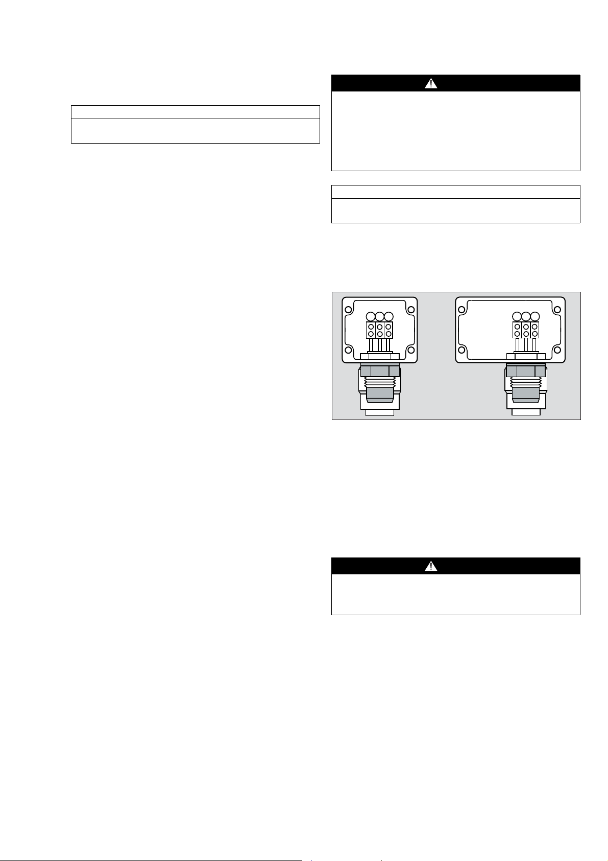
Service and Maintenance
Replacing the DrägerSensor
Maintenance Intervals
NOTICE
Observe standard EN 60079-29-2 and/or the relevant
national laws and regulations:
Daily
z Visual inspection to establish readiness for opera-
tion.
Before operation:
z Setting the sensor current, page 36.
z Calibrating / adjusting the sensing head, page 37.
At regular intervals,
as specified by those responsible for the gas detection
system and which should not exceed an interval of
6months:
z Check signal transmission to control unit, and alarm
triggering, see instructions for use of the appropriate
central controller.
z Calibrating / adjusting the Sensing head, page 37.
The interval for regular calibration depends on the
environmental conditions of use.
Especially it must regularly be ensured that gas can
freely enter the sensor and that there are neither corrosion nor deposits of dust, oil or aerosols.
WARNiNG
It is not allowed to replace the DrägerSensor while it is
energized in the hazardous area.
Furthermore also in the safe area the controller has to
be switched-off before replacing the DrägerSensor.
Otherwise the DrägerSensor might be destroyed during the connection procedure.
NOTICE
Observe national regulations for installing electrical
devices in hazardous areas (in Europe EN 60 079-14).
z Switch off the controller or remove the corresponding
channel module.
Sensing Heads Polytron SE Ex PR M1/2 DD and
SE Ex LC M1/2 DD
1 2 3
1
2
3
1 2 3
1
2
3
Every six months
z Arrange for inspection by trained personnel.
The inspection intervals in each individual case are in-
fluenced and if necessary shortened by technical safety
considerations, engineering processes and the technical requirements of the equipment.
We recommend a DrägerService contract which also
covers repairs.
If necessary
z Replace sensor, page 39.
z After having switched-off the voltage open the termi-
nal box of the sensing head and remove the upper
section.
1 Disconnect the sensor leads from the terminals.
2 Unscrew hexagon nut.
3 Remove old sensor. Shorten sensor leads of the
new sensor adequately and cut-off the isolation by
approx. 8 to 10 mm. Use ferrules enclosed.
4 Screw in new sensor and secure the hexagon nut
against self-loosening e.g. with Loctite No. 221.
WARNiNG
To maintain the ingress protection IP 66 and for reasons of explosion protection observe that the sensor’s
O-ring is tightly fitted.
5 Connect sensor leads to terminals:
Terminal 1 – brown lead
Terminal 2 – yellow lead
Terminal 3 – black lead
z Close the terminal box ensuring it is dust free.
39
Page 40

Sensing Heads Polytron SE Ex PR M3 DD and
SE Ex LC M
3 DD
z After having
switched-off the voltage open the terminal box of the sensing head and remove
1
4
3
2
1
the upper section.
1 Disconnect the
sensor leads from
2
the terminals and
unscrew old sensor.
2 Remove old sensor. Shorten sensor leads of the
new sensor adequately and nd cut-off the isolation
by approx. 8 to 10 mm. Use ferrules enclosed.
3 Screw in new sensor and secure it against self-
loosening e.g. with Loctite No. 221.
WARNING
To maintain the ingress protection IP 66 and for reasons of explosion protection observe that the sensor’s
O-ring is tightly fitted.
4 Connect sensor leads to terminals:
Terminal 1 – brown lead
Terminal 2 – yellow lead
Terminal 3 – black lead
z Close the terminal box ensuring it is dust free.
Sensing Heads Polytron SE Ex PR NPT1 DD and
SE Ex LC NPT1 DD
z After having
switched-off the voltage open the terminal box of the sensing head and remove
1
4
3
2
1
the upper section.
1 Disconnect the
sensor leads from
2
the terminals 1, 2
and 3.
2 Unscrew and re-
move old sensor. Cut-off sensor connector, shorten the sensor leads adequately and cut-off the
insulation by approx. 8 to 10 mm. Use ferrules enclosed.
Screw the new sensor tightly into the port. Five
threads must be engaged to ensure the type of
protection “d”.
3 Connect sensor leads to terminals:
Terminal 1 – brown lead
Terminal 2 – yellow lead
Terminal 3 – black lead
Terminal 4 (if existing) is not connected
z Close the terminal box while considering the relevant
explosion protection rules. Ensure the housing is
free of dust and lock the headless screw of the cover.
Sensing Head Polytron SE Ex HT M
z After having
switched-off the voltage open the terminal box of the sensing head and remove
the upper section.
1
2
3
4
PE
1 Disconnect the
sensor leads from
2
01533176.eps
the terminals 1, 2,
and 3.
2 Remove old sen-
sor and replace it by a new sensor. Shorten the
sensor cables adequately and cut-off the isolation
by approx. 8 to 10 mm. Use ferrules enclosed.
3 Screw in new sensor and secure it against self-
loosening e.g. with Loctite No. 221.
WARNING
To maintain the ingress protection IP 66 and for reasons of explosion protection observe that the sensor’s
silicone gasket is tightly fitted.
4 Connect sensor leads to terminals:
Terminal 1 – brown lead
Terminal 2 – yellow lead
Terminal 3 – black lead
Terminal 4 (if existing) is not connected
z Securely fit the cover to the body of the enclosure
and tighten the cover fixing screws by a torque of
3.5 Nm.
Make sure the enclosure is free of dust and the silicone gasket is secured between the body and the
cover.
Switch-on after Sensor Replacement
z Switch on power of the controller resp. insert the cor-
responding channel module.
NOTICE
01633176.eps
Observe warm-up time of the new sensor of at least
30 minutes.
z Start the calibration procedure, page 37 - after each
sensor replacement.
WARNING
For reasons of explosion protection the DrägerSensor
of the sensing heads Polytron SE Ex LC M1/2/3 DD
and Polytron SE Ex LC NPT1 DD is only allowed to be
disassembled (opened and closed) by the Dräger
Service using a special tool.
1
01733176.eps
40
Page 41

Selection of detectable Gases and
Vapours
The table below is not necessarily complete. It lists only
those gases and vapours that have been subjected to
performance testing complying with EN 60079-29-1.
The sensing heads can also detect other substances
not listed here. The typical sensor signals detected apply to unused sensors and can fluctuate by up to
± 30 %. The lower explosion limits given here are taken
from IEC 60079-20-1:2010, in specific regions, other
lower explosion limits may be compulsory.
Sensing heads Polytron SE Ex PR M1/2/3 DD,
SE Ex PR NPT1 DD and Polytron SE Ex HT M DD
Gas or vapour
(Gases indented)
Acetone 67-64-1 2.5 37.8 7-10 15-18
Acetylene 74-86-2 2.3 43.1 7-10 15-18
Ammonia 7664-41-7 15.0 71.1 7-9 12-15
Benzene 71-43-2 1.2 30.7 10-13 22-26
1.3-Butadiene 106-99-0 1.4 33.4 9-11 19-22
n-Butane 106-97-8 1.4 32.8 9-12 20-24
n-Butyl acetate 123-86-4 1.2 24.2 12-15 28-31
Diethylether 60-29-7 1.7 32.9 11-14 25-28
Dimethylether 115-10-6 2.7 38.5 8-10 18-20
Ethanol 64-17-5 3.1 39.5 9-12 20-22
Ethyl acetate 141-78-6 2.0 30.7 12-14 23-28
Ethylene (Ethene) 74-85-1 2.3 41.3 7-10 16-19
Ethylene oxide 75-21-8 2.6 35.1 7-11 17-20
n-Hexane 110-54-3 1.0 26.7 11-13 23-27
Hydrogen 1333-74-0 4.0 51.0 4 11 5-7 10-13
Methane 74-82-8 4.4 60.0 5 8-10 7-9 14-17
Methanol 67-56-1 6.0 49.3 9-10 18-21
Methyl methacrylate 80-62-6 1.7 30.7 10-12 23-26
Methylethylketone 78-93-3 1.5 28.4 11-12 22-25
n-Nonane 111-84-2 0.7 21.5 13-14 27-33
n-Octane 111-65-9 0.8 23.7 12-14 25-29
n-Pentane 109-66-0 1.1 27.2 11-13 25-31
Petrol 065/095 --- 1.1 30.2 10-13 22-26
Propane 74-98-6 1.7 35.0 4-6 9-13 8-11 18-23
i-Propanol 67-63-0 2.0 32.7 9-12 20-23
Propylene (Propene) 115-07-1 2.0 41.3 7-11 17-20
Propylene oxide 75-56-9 1.9 32.6 10-12 20-23
Toluene 108-88-3 1.0 27.0 10-12 24-28
o-Xylene 95-47-6 1.0 27.9 12-13 29-35
CAS-No. LEL
in
% V/V at 255 mA t50 t90 t50 t90
Typical sensor
signal at 50
%LEL in mV
Response time
in seconds at
255 mA
1)
Response time
in seconds at
255 mA
2)
1) Response times acc. to EN 60079-29-1, Appendix B, B.2.3.1 (diffusion mode without directed flow).
2) Response times acc. to EN 60079-29-1, Appendix B, B.2.2 (span gas applied by calibration adapter).
41
Page 42

Sensing heads Polytron SE Ex LC M1/2/3 DD and
SE Ex LC NPT1 DD
Gas or Vapour
(Gases indented)
Acetone 67-64-1 2.5 5 %LEL 1250 17.0
Acetylene 74-86-2 2.3 5 %LEL 1150 26.5
Ammonia 7664-41-7 15.0 5 %LEL 7500 23.5
Benzene 71-43-2 1.2 5 %LEL 600 15.5
1.3-Butadiene 106-99-0 1.4 5 %LEL 700
n-Butane 106-97-8 1.4 5 %LEL 700
n-Butyl acetate 123-86-4 1.2 5 %LEL 600 7.0
Cyclopropane 75-19-4 2.4 5 %LEL 1200
Diethylether 60-29-7 1.7 5 %LEL 850
Dimethylether 115-10-6 2.7 5 %LEL 1350
Ethanol 64-17-5 3.1 5 %LEL 1550 18.5
Ethyl acetate 141-78-6 2.0 5 %LEL 1000 25.0
Ethylene (Ethene) 74-85-1 2.3 5 %LEL 1150 21.5
Ethylene oxide 75-21-8 2.6 5 %LEL 1300
n-Hexane 110-54-3 1.0 5 %LEL 500 12.0
Hydrogen 1333-74-0 4.0 5 %LEL 2000 27.5
Methane 74-82-8 4.4 5 %LEL 2200 25.5
Methanol 67-56-1 6.0 5 %LEL 3000 26.0
Methyl methacrylate 80-62-6 1.7 5 %LEL 850
Methylethylketone 78-93-3 1.5 5 %LEL 750 13.0
n-Nonane 111-84-2 0.7 5 %LEL 350 7.0
n-Octane 111-65-9 0.8 5 %LEL 400 9.5
n-Pentane 109-66-0 1.1 5 %LEL 550 12.5
Petrol 065/095 --- 1.1 5 %LEL 550
Propane 74-98-6 1.7 5 %LEL 850 18.0
i-Propanol 67-63-0 2.0 5 %LEL 1000 23.0
Propylene (Propene) 115-07-1 2.0 5 %LEL 1000 27.5
Propylene oxide 75-56-9 1.9 5 %LEL 950 21.0
Toluene 108-88-3 1.0 5 %LEL 500 11.5
CAS-No. LEL
in
% V/V in %LEL in ppm at 276 mA
Concentration Typical sensor sig-
nal at 5 %LEL in mV
42
Page 43

Technical Data
Sensing Heads Polytron SE Ex PR M1/2/3 DD and Polytron SE Ex PR NPT1 DD
Operating parameters
- constant sensor current 255 / 270 mA
- voltage at test points 561 / 594 mV (Controller unit Polytron SE Ex)
Enclosure protection acc. to EN 60 529: IP 66
Device description acc. to 94/9/EG: Dräger Safety, D-23560 Lübeck, Germany
Polytron SE Ex PR M1/2/3 DD
II 2G Ex de IIC T6/T5/T4
II 2D Ex tD A21 IP 6x T130°C
Polytron SE Ex PR NPT1 DD
II 2G Ex d IIC T6/T5/T4
II 2D Ex tD A21 IP 6x T130°C
BVS 10 ATEX E 060 X, IECEx BVS 10.0045X
CE-marking with number of Notified Body
year of construction by serial number
Sensing Heads Polytron SE Ex LC M1/2/3 DD and Polytron SE Ex LC NPT1 DD
Operating parameters
- constant sensor current 276 mA
- voltage at test points 607 mV (Controller unit Polytron SE Ex)
Enclosure protection acc. to EN 60 529: IP 66
Device description acc. to 94/9/EG: Dräger Safety, D-23560 Lübeck, Germany
Polytron SE Ex LC M1/2/3 DD
II 2G Ex de IIC T6/T5/T4
II 2D Ex tD A21 IP 6x T130°C
Polytron SE Ex LC NPT1 DD
II 2G Ex d IIC T6/T5/T4
II 2D Ex tD A21 IP 6x T130°C
BVS 10 ATEX E 060 X, IECEx BVS 10.0045X
CE-marking with number of Notified Body
year of construction by serial number
1)
1)
Environmental Conditions
Sensing Heads Polytron SE Ex PR M1/2/3 DD and Polytron SE Ex PR NPT1 DD as well as
sensing Heads Polytron SE Ex LC M1/2/3 DD and Polytron SE Ex LC NPT1 DD
Operation: Temperature ranges see “Ambient Temperature and
Temperature Classes” on page 27.
800 to 1100 hPa
5 to 95 % rel. humidity, non-condensing
Storage (also for replacement sensors) -40 to +65 °C
700 to 1300 hPa
10 to 90 % rel. humidity, non-condensing
storage time unlimited
1) Year of construction is coded by the third capital letter of the serial number on
the type plate: Z = 2008, A = 2009, B = 2010, C = 2011, D = 2012, E = 2013, etc.
Example: Serial number ARBH-0054, the 3rd capital letter is B, so the year of construction is 2010.
43
Page 44

Sensing Head Polytron SE Ex HT M DD
Operating parameters
- constant sensor current 255 / 270 mA
- voltage at test points 561 / 594 mV (Controller unit Polytron SE Ex)
Enclosure protection acc. to EN 60 529: IP 66
Device description acc. to 94/9/EG: Dräger Safety, D-23560 Lübeck, Germany
Polytron SE Ex HT M DD
year of construction by serial number
1)
1. DrägerSensor HT M DD: Dräger Safety, D-23560 Lübeck, Germany
DrägerSensor Ex HT M
II 2G Ex d IIC T6/T5/T4/T3
II 2D Ex tD A21 IP 6x T130/T195°C
DEMKO 09 ATEX 0924202 X
CE 0158, year of construction by serial number
1)
2. Enclosure (junction box): Flameproof Electrical Enclosures Ltd., Oldbury, England
Typ Range 2000
II 2G Ex e II T3
II 2D Ex tD A21 IP 66 T200°C
SIRA 06 ATEX 3153
CE 0518, year of construction
3. Cable gland: Peppers Cable Glands Ltd., Surrey GU15 3BT, UK
Typ A3LF
Ex e II
II 2G
II 2D tD A21 IP68
SIRA 01
ATEX 1272X
Environmental Conditions
Operation: Temperature ranges see “Ambient Temperature and
Temperature Classes” on page 27.
800 to 1100 hPa,
5 to 95 % rel. humidity, non-condensing
Storage (also for replacement sensors) -40 to +65 °C
700 to 1300 hPa
10 to 90 % rel. humidity, non-condensing
storage time unlimited
1) Year of construction is coded by the third capital letter of the serial number on
the type plate: Z = 2008, A = 2009, B = 2010, C = 2011, D = 2012, E = 2013, etc.
Example: Serial number ARBH-0054, the 3rd capital letter is B, so the year of construction is 2010.
44
Page 45

Order List Dimensions
Name and description Order-No.
Measuring range 0 ... 100 %LEL
Sensing head Polytron SE Ex PR M1 DD 68 12 711
Sensing head Polytron SE Ex PR M2 DD 68 12 710
Sensing head Polytron SE Ex PR M3 DD 68 12 718
Sensing head
68 12 800
Polytron SE Ex PR NPT1 DD
for conduit-piping 3/4” NPT,
without cable gland
Measuring range 0 ... 10 %LEL
1)
Sensing head Polytron SE Ex LC M1 DD 68 12 722
Sensing head Polytron SE Ex LC M2 DD 68 12 721
Sensing head Polytron SE Ex LC M3 DD 68 12 719
Sensing head Polytron
68 12 801
SE Ex LC NPT1 DD for conduit-piping
3/4” NPT, without cable gland
Measuring range 0 ... 100 %LEL for
high temperatures
Sensing head Polytron SE Ex HT M DD 68 12 720
Accessories
Calibration adapter (PE)
68 06 978
(max. operation temperature 70 °C)
Process adapter
1)
68 12 470
(stainless steel, with locking nut
M30 x 1.5) for DrägerSensor PR M DD
and DrägerSensor PR NPT DD
Process adapter
1)
68 12 465
(stainless steel, with locking nut
M36 x 1.5) for DrägerSensor LC M and
DrägerSensor LC NPT
Dust filter
1) 2)
68 10 537
(10 pcs, PTFE discs)
for DrägerSensor PR M DD and
DrägerSensor PR NPT DD
Sensing head
Polytron SE Ex PR M1 DD
incl. sensor and cable gland
Sensing head
Polytron SE Ex LC M1 DD
incl. sensor and cable gland
Sensing head
Polytron SE Ex PR M2 DD incl.
sensor and sidewise cable gland
Sensing head
Polytron SE Ex LC M2 DD incl.
sensor and sidewise cable gland
Sensing head
Polytron SE Ex PR M3 DD
incl. sensor and cable gland
Sensing head
Polytron SE Ex LC M3 DD
incl. sensor and cable gland
Sensing head
Polytron SE Ex PR NPT1 DD
incl. sensor
Sensing head
Polytron SE Ex LC NPT1 DD
incl. sensor
Sensing head
Polytron SE Ex HT M DD
incl. sensor and cable gland
W x H x D in mm
80 x 130 x 56
80 x 145 x 56
136 x 107 x 56
136 x 124 x 56
147 x 154 x 75
147 x 168 x 75
101 x 142 x 75
101 x 160 x 75
150 x 152 x 85
Spare parts
DrägerSensor PR M DD 68 12 220
DrägerSensor PR NPT DD 68 12 380
DrägerSensor LC M 68 10 350
DrägerSensor LC NPT 68 10 675
DrägerSensor HT M DD 68 12 390
1) The four sensing heads with the identification "LC" (measuring
range 0 ... 10 %LEL) with their corresponding sensors, both the
process adapters and the dust filter were not subject to the part of
the performance test acc. to EN 60079-29-1.
2) Response times may increase when using the dust filter.
45
Page 46

Dimensions and Drilling Measures
(in mm)
Sensing head Polytron SE Ex PR M1 DD
Sensing head Polytron SE Ex LC M1 DD
68
4.5
45
Sensing head Polytron SE Ex PR M3 DD
Sensing head Polytron SE Ex LC M3 DD
103
01833176.eps
7
103
02033176.eps
Sensing head Polytron SE Ex PR M2 DD
Sensing head Polytron SE Ex LC M2 DD
98
4.5
45
01933176.eps
46
Page 47

Sensing head Polytron SE Ex PR NPT1 DD
02133176.eps
77.8
77.8
110
02233176.eps
125
88
ca.12
88
A
Sensing head Polytron SE Ex LC NPT1 DD
(Diameter of both the wall fixing holes: 7 mm)
Sensing head Polytron SE Ex HT M DD
(Diameter of both the wall fixing holes: 6mm)
A wall fixing hole
47
Page 48

Zulassungen/Approvals
48
Page 49

49505152535455
Page 50

Page 51

Page 52

Page 53

Page 54

Page 55

Page 56

EG-Konformitätserklärungen/EC-Declarations of Conformity
56
Page 57

575859
Page 58

Page 59

Page 60

Dräger Safety AG & Co. KGaA
Revalstraße 1
D-23560 Lübeck
Germany
Phone +49 451 882-0
Fax +49 451 882-20 80
www.draeger.com
90 33 176 - GA 4675.740 de/en
© Dräger Safety AG & Co. KGaA
Edition 02 - October 2010 (Edition 01 - July 2010)
Subject to alteration
 Loading...