

Page 1

Dräger PIR 3000
en
Infrared Gas Transmitter
Instructions for Use
00123812_02.eps
0
S
Page 2

Contents
2
Contents
For Your Safety . . . . . . . . . . . . . . . . . . . . . . . . . . . . . . . . . . . . . . . . . . . . . . . . . . . . . . . . . . . . . . . . . . . . . . . . . . . . . . . . . . . . 3
Intended Use . . . . . . . . . . . . . . . . . . . . . . . . . . . . . . . . . . . . . . . . . . . . . . . . . . . . . . . . . . . . . . . . . . . . . . . . . . . . . . . . . . . . . . 4
Explosion-Protection Approvals . . . . . . . . . . . . . . . . . . . . . . . . . . . . . . . . . . . . . . . . . . . . . . . . . . . . . . . . . . . . . . . . . . . . . . 5
Installing the Gas Transmitter . . . . . . . . . . . . . . . . . . . . . . . . . . . . . . . . . . . . . . . . . . . . . . . . . . . . . . . . . . . . . . . . . . . . . . . . 6
Mounting Location . . . . . . . . . . . . . . . . . . . . . . . . . . . . . . . . . . . . . . . . . . . . . . . . . . . . . . . . . . . . . . . . . . . . . . . . . . . . . . . . . . . 6
Mechanical Installation . . . . . . . . . . . . . . . . . . . . . . . . . . . . . . . . . . . . . . . . . . . . . . . . . . . . . . . . . . . . . . . . . . . . . . . . . . . . . . . 6
When used according to BVS 05 ATEX E 143 X, please note: . . . . . . . . . . . . . . . . . . . . . . . . . . . . . . . . . . . . . . . . . . . . . . 6
Terminal box . . . . . . . . . . . . . . . . . . . . . . . . . . . . . . . . . . . . . . . . . . . . . . . . . . . . . . . . . . . . . . . . . . . . . . . . . . . . . . . . . . . . 6
Splash Guard and Calibration Adapter . . . . . . . . . . . . . . . . . . . . . . . . . . . . . . . . . . . . . . . . . . . . . . . . . . . . . . . . . . . . . . . . 6
Gas Exposure / Process Adapter (see "Accessories/Spare parts" on page 27) . . . . . . . . . . . . . . . . . . . . . . . . . . . . . . . . . 7
Dirt Deflector (see "Accessories/Spare parts" on page 27) . . . . . . . . . . . . . . . . . . . . . . . . . . . . . . . . . . . . . . . . . . . . . . . . . 7
Electrical Installation . . . . . . . . . . . . . . . . . . . . . . . . . . . . . . . . . . . . . . . . . . . . . . . . . . . . . . . . . . . . . . . . . . . . . . . . . . . . . . . . . 8
When used according to BVS 05 ATEX E 143 X, please note: . . . . . . . . . . . . . . . . . . . . . . . . . . . . . . . . . . . . . . . . . . . . . . 9
Commissioning . . . . . . . . . . . . . . . . . . . . . . . . . . . . . . . . . . . . . . . . . . . . . . . . . . . . . . . . . . . . . . . . . . . . . . . . . . . . . . . . . . . . 10
Operational Characteristics . . . . . . . . . . . . . . . . . . . . . . . . . . . . . . . . . . . . . . . . . . . . . . . . . . . . . . . . . . . . . . . . . . . . . . . . . 11
Calibration . . . . . . . . . . . . . . . . . . . . . . . . . . . . . . . . . . . . . . . . . . . . . . . . . . . . . . . . . . . . . . . . . . . . . . . . . . . . . . . . . . . . . . . . 11
Configuration of the Gas Transmitter via Magnetic Pin . . . . . . . . . . . . . . . . . . . . . . . . . . . . . . . . . . . . . . . . . . . . . . . . . . . . . . 13
Automatic Zerosetting . . . . . . . . . . . . . . . . . . . . . . . . . . . . . . . . . . . . . . . . . . . . . . . . . . . . . . . . . . . . . . . . . . . . . . . . . . . . 13
Manual Zero Calibration of the Output Signal. . . . . . . . . . . . . . . . . . . . . . . . . . . . . . . . . . . . . . . . . . . . . . . . . . . . . . . . . . . 14
Manual Span Calibration of the Output Signal. . . . . . . . . . . . . . . . . . . . . . . . . . . . . . . . . . . . . . . . . . . . . . . . . . . . . . . . . . 15
Substitute Gas Calibration . . . . . . . . . . . . . . . . . . . . . . . . . . . . . . . . . . . . . . . . . . . . . . . . . . . . . . . . . . . . . . . . . . . . . . . . . 16
Checking the Signal Transmission, Checking the Alarm Trigger and Displaying the Gas Category . . . . . . . . . . . . . . . . . 17
Changing the gas category . . . . . . . . . . . . . . . . . . . . . . . . . . . . . . . . . . . . . . . . . . . . . . . . . . . . . . . . . . . . . . . . . . . . . . . . 18
Maintenance . . . . . . . . . . . . . . . . . . . . . . . . . . . . . . . . . . . . . . . . . . . . . . . . . . . . . . . . . . . . . . . . . . . . . . . . . . . . . . . . . . . . . . 20
Faults, Cause and Remedy . . . . . . . . . . . . . . . . . . . . . . . . . . . . . . . . . . . . . . . . . . . . . . . . . . . . . . . . . . . . . . . . . . . . . . . . . . 21
Technical Data . . . . . . . . . . . . . . . . . . . . . . . . . . . . . . . . . . . . . . . . . . . . . . . . . . . . . . . . . . . . . . . . . . . . . . . . . . . . . . . . . . . . 22
General Details . . . . . . . . . . . . . . . . . . . . . . . . . . . . . . . . . . . . . . . . . . . . . . . . . . . . . . . . . . . . . . . . . . . . . . . . . . . . . . . . . . . . 22
Measuring Technique Characteristics . . . . . . . . . . . . . . . . . . . . . . . . . . . . . . . . . . . . . . . . . . . . . . . . . . . . . . . . . . . . . . . . . . . 23
Cross Sensitivities . . . . . . . . . . . . . . . . . . . . . . . . . . . . . . . . . . . . . . . . . . . . . . . . . . . . . . . . . . . . . . . . . . . . . . . . . . . . . . . . . . 24
Dimensions . . . . . . . . . . . . . . . . . . . . . . . . . . . . . . . . . . . . . . . . . . . . . . . . . . . . . . . . . . . . . . . . . . . . . . . . . . . . . . . . . . . . . . . 25
Description of Design . . . . . . . . . . . . . . . . . . . . . . . . . . . . . . . . . . . . . . . . . . . . . . . . . . . . . . . . . . . . . . . . . . . . . . . . . . . . . . 26
Order List . . . . . . . . . . . . . . . . . . . . . . . . . . . . . . . . . . . . . . . . . . . . . . . . . . . . . . . . . . . . . . . . . . . . . . . . . . . . . . . . . . . . . . . . 27
Dräger PIR 3000 infrared gas transmitter . . . . . . . . . . . . . . . . . . . . . . . . . . . . . . . . . . . . . . . . . . . . . . . . . . . . . . . . . . . . . . . . 27
Accessories/Spare parts . . . . . . . . . . . . . . . . . . . . . . . . . . . . . . . . . . . . . . . . . . . . . . . . . . . . . . . . . . . . . . . . . . . . . . . . . . . . . 27
ATEX - Approval . . . . . . . . . . . . . . . . . . . . . . . . . . . . . . . . . . . . . . . . . . . . . . . . . . . . . . . . . . . . . . . . . . . . . . . . . . . . . . . . . . . 28
IECEx - Approval . . . . . . . . . . . . . . . . . . . . . . . . . . . . . . . . . . . . . . . . . . . . . . . . . . . . . . . . . . . . . . . . . . . . . . . . . . . . . . . . . . 48
UL - Approval . . . . . . . . . . . . . . . . . . . . . . . . . . . . . . . . . . . . . . . . . . . . . . . . . . . . . . . . . . . . . . . . . . . . . . . . . . . . . . . . . . . . . 54
CSA - Approval . . . . . . . . . . . . . . . . . . . . . . . . . . . . . . . . . . . . . . . . . . . . . . . . . . . . . . . . . . . . . . . . . . . . . . . . . . . . . . . . . . . 57
Declaration of Conformity
. . . . . . . . . . . . . . . . . . . . . . . . . . . . . . . . . . . . . . . . . . . . . . . . . . . . . . . . . . . . . . . . . . . . . . . . . . . 60
Page 3

3
For Your Safety
For Your Safety
Strictly follow these Instructions for Use
Any use of this gas transmitter requires full understanding of the information
provided and strict adherence to the instructions given.
The gas transmitter is only to be used for the purposes specified here.
Maintenance
Maintenance jobs may only be carried out by trained service personnel.
We recommend signing a service contract to have all maintenance jobs carried out
by Dräger.
Always use original Dräger parts for maintenance.
Be sure to read the information provided in the chapter "Maintenance".
Accessories
Only use accessories mentioned in the order list.
Safe Connection of Electrical Devices
Never connect this device to other electrical devices not mentioned in these
Instructions for Use before consulting the manufacturer or an expert.
Use in Potentially Explosive Atmospheres
Devices or components used in potentially explosive atmospheres after being
tested and approved according to national, European or international regulations
may only be used under the conditions specified in the approval and under
observation of relevant legal regulations.
Never modify the electrical equipment.
Never use defective or incomplete parts. Always take relevant regulations into
account when repairing devices or components.
Safety symbols used in these Instructions for Use
These Instructions for Use contain a number of warnings for risks and hazards
which might occur when using the instrument. These warnings contain signal words
which will alert you to the degree of hazard you may encounter. These signal words
and corresponding hazards are as follows:
WARNING
Explosion hazard! Do not open sensor housing. There is a risk of ignition in
explosive atmospheres. The sensor housing contains live parts. Unauthorised
opening can lead to a safety-related failure of the sensor. The sensor does not
contain any parts that can be serviced by the user.
WARNING
Indicates a potentially hazardous situation which, if not avoided, could result in
death or serious injury.
CAUTION
Indicates a potentially hazardous situation which, if not avoided, could result in
physical injury, or damage to the product or environment. It may also be used to
alert against unsafe practices.
NOTICE
Indicates additional information on how to use the product.
Page 4

Intended Use
4
Intended Use
The Dräger PIR 3000 infrared gas transmitter is a device used for stationary,
continuous monitoring of the concentration of carburetted, combustible gases and
vapours in the ambient air.
The gas transmitter is preconfigured for the gases methane, propane and ethylene.
The operating range respectively covers 0 to 100 %LEL (Lower Explosion Limit).
An analogue, 4 to 20 mA output signal is used as measuring value output.
The Dräger PIR 3000 infrared gas transmitter is designed for use in rough ambient
conditions and is suited for installation in hazardous areas of zones 1, 2, 21 and 22
according to the device categories 2G, 3G, 2D, 3D or Class I & II, Div. 1 for
hazardous areas. For further information, please observe the installation
instructions.
In connection with a central device (e.g. Dräger REGARD channel card
4...20 mA):
— warning before explosive concentration level is reached
— automatic initiation of countermeasures which avert the explosion hazard (e.g.
switching on a ventilation)
— device error warning
00223812_01.eps
0
S
00223812_01.eps
0
S
Page 5

5
Explosion-Protection Approvals
Explosion-Protection Approvals
The explosion-protection approvals are valid for use of the device in gas/vapour-air mixtures of combustible gases and
vapours under atmospheric conditions. The explosion-protection approvals are not valid for use in oxygen-enriched
atmospheres. Unauthorised opening of the enclosure invalidates the explosion-protection approval.
The appendix has a copy of the ATEX certificate, which offers relevant information on safety regulations under subjects such
as "Subject matter and type", "Description", "Characteristic quantity" and "Terms/conditions of safe use".
—ATEX Type IDS 0001
II 2G Ex db IIC T6 Gb
II 2D Ex tb IIIC T80°C Db IP6X
–40 °C ≤ Ta ≤ +65 °C
Type ITR 001X
II 2G Ex db IIC T6 Gb
II 2D Ex tb IIIC T80°C Db IP6X
–40 °C ≤ Ta ≤ +60 °C
Types IDS 0011 and ITR 000X:
II 2G Ex db eb IIC T6 Gb
II 2D Ex tb IIIC T80°C Db IP6X
–40 °C ≤ Ta ≤ +65 °C
year of construction (by serial number)
1)
BVS 05 ATEX E 143X
1) The year of manufacture is indicated by the third letter of the serial number on the type plate: X = 2006, Y = 2007, Z = 2008,
A = 2009, B = 2010, C = 2011, D = 2012, etc.
example: serial number ARXH-0054, the third letter is U, so the year of manufacture is 2006.
— IECEx Type IDS 0001:
Ex db IIC T6, Ex tb IIIC T80°C Db IP6X
–40
o
C ≤ Ta ≤ +65 oC
Type ITR 001X
Ex db IIC T6 Gb, Ex tb IIIC T80°C Db IP6X
–40 °C ≤ Ta ≤ +60 °C
Types IDS 0011 and ITR 000X:
Ex db eb IIC T6, Ex tb IIIC T80°C Db IP6X
–40 °C ≤ Ta ≤ +65 °C
BVS 05.0011X
—UL
(Underwriters Laboratories Inc.)
Type IDS 0001:
Class I, Div. 1, Groups A, B, C, D
Class II, Div. 1, Groups E, F, G
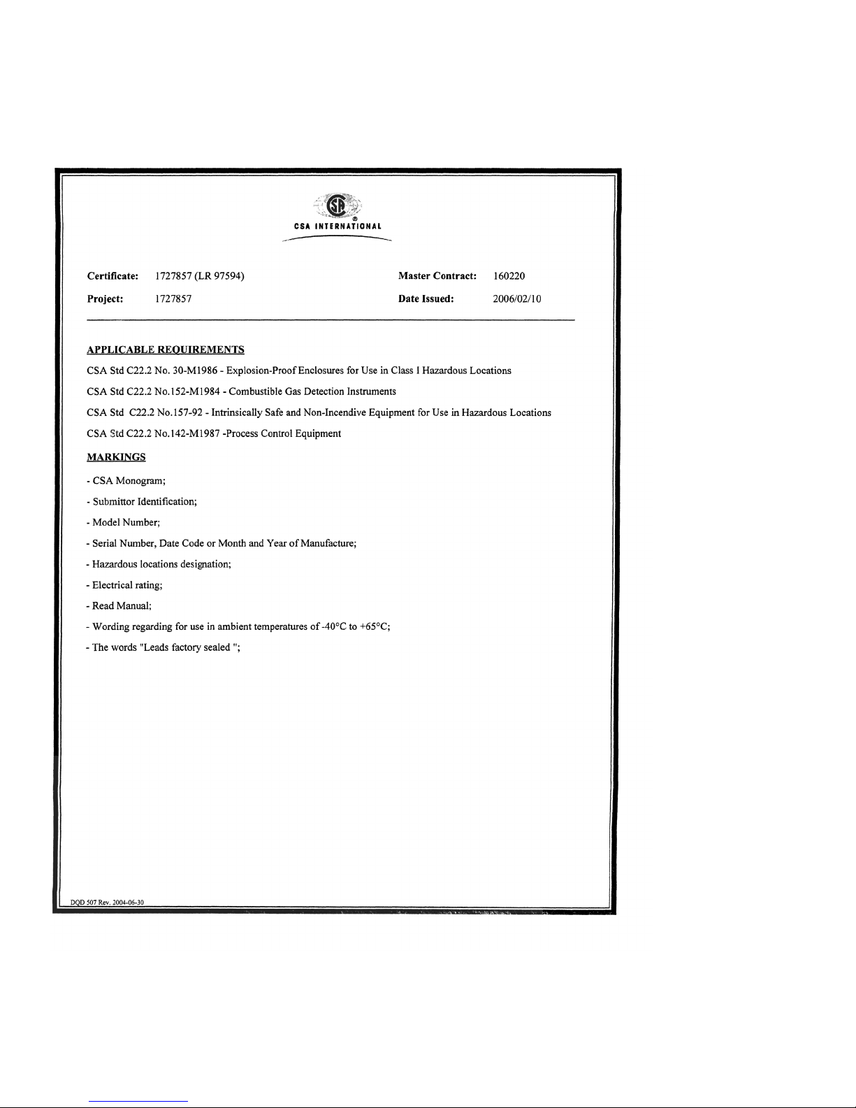
—CSA Type IDS 0001:
Class I, Div. 1, Groups A, B, C, D
C22.2, No. 152
0158
0158
0158
CU
S
®
LR97594
Page 6

Installing the Gas Transmitter
6
Installing the Gas Transmitter
Only trained service personnel (e.g. of Dräger) may install the gas transmitter
under observation of relevant regulations.
Installation and commissioning are described in the "Dräger PIR 3000 Installation
Instructions" which are supplied with the gas transmitter.
Mounting Location
The protecting effect of the gas transmitter depends on the selection of the
mounting location. By taking the site's air flow conditions into account, the best
possible mounting location should be chosen as close as possible to where a
decisively noticeable rise in gas concentration can be expected in case of a
leakage, i. e.
— as close as possible to the potential leakage place
— when monitoring gases and vapours which are lighter than air:
above the potential leakage place
— when monitoring gases and vapours which are heavier than air:
near to ground.
In addition, it must be assured that:
— the air circulation in the gas transmitter vicinity is not hindered
— the danger of mechanical damage is reduced as far as possible
— the gas transmitter is sufficiently accessible for maintenance purposes.
Especially the configuration via magnetic pin requires a clearance of approx.
20 cm around at least half of the sensor perimeter.
The gas transmitter can be mounted horizontally as well as vertically.
Mechanical Installation
When used according to BVS 05 ATEX E 143 X, please note:
The gas sensor type IDS 0001 (NPT) can be attached to casings with the type
of protection flameproof enclosure "d" that have a free volume of 2 litres and a
reference pressure that does not exceed 20 bar. The mechanical strength of the
attachment and the explosion and construction-related testing of the connection
thread must be carried out within the framework of the approval process of the
electrical equipment to which the sensor is attached.
The gas sensor type IDS 0011 (metric thread) is designed for attachment on a
casing with the type of protection increased safety "e". The mechanical strength
and the degree of protection IP 6X of the attachment must be ensured during
approval of the electrical equipment to which it is attached.
The junction boxes of the gas sensors IDS 00** must feature sufficient
mechanical stability to ensure that the vibrations transmitted to the sensor by the
casing are not amplified.
Terminal box
The gas transmitter is designed to be directly attached to a terminal box.
Approved connector boxes of the following makes are available as gas transmitter
accessories: Ex d (explosion proof, 3/4" NPT) and Ex e (increased safety, M25) (see "Order List" on page 27).
To maintain the housing protection class, the enclosed O-ring seal must be used
for an Ex e-type explosion protection connection.
Use a thread locking adhesive, e.g. Loctite
®
to prevent the M25 nut (torque of
15 Nm ±3 Nm) from self-loosening.
Use approved plugs to close any unused cable entry openings at the terminal
box.
Splash Guard and Calibration Adapter
We recommend using the supplied accessories - splash guard (1) and calibration
adapter (2) - to increase protection against water jets and contamination.
0
S
00323812_02.eps
(1)
(2)
Page 7

7
Installing the Gas Transmitter
The splash guard is held by a fixture provided with screw-thread, which is also used
as calibration adapter.
Make sure that the calibration adapter is correctly seated. To this end, manually
tighten the calibration adapter to a point where the sealing line leaves a permanent
mark on the splash guard.
Gas Exposure / Process Adapter (see "Accessories/Spare parts" on page 27)
For continuous flow operation of the gas transmitter, the calibration adapter can be
replaced with an optional gas exposure / process adapter.
— Suitable for flow rates between 1 and 3 L/min.
— Within the specified technical measurement characteristics suitable for pressure
differences relative to ambient pressure of up to ±300 hPa.
— Use external pump to ensure gas flow.
— External flow monitoring required.
— Also suitable for calibration gas application.
Assembly:
Unscrew the calibration adapter from the gas transmitter. While doing so, leave
splash guard on the gas transmitter.
Screw gas exposure / process adapter onto the gas transmitter and tighten firmly
by hand.
In the case of pipelines and hose lines carrying gas ensure that there is stability
with regard to ambient conditions and material compatibility for the substances
flowing through them.
With regard to the length of the pipelines or hose lines observe the increase in
the response time.
Ensure the compatibility of the connection spouts to be used regarding the
pipeline and hose line dimensions.
Check the gas-carrying system for leaks, e.g. with a soap bubble test.
Dirt Deflector (see "Accessories/Spare parts" on page 27)
Instead of the calibration adapter, a double-walled dirt deflector can optionally be
fitted to the gas transmitter. This is recommended if there is an increased risk of
contamination from e.g. salt crusts, oil films, resin or similar substances, and also
generally for outdoor applications. In addition to the dirt deflector, the use of a
splash guard is strongly recommended.
Also suitable for calibration gas application.
Assembly:
— Unscrew the calibration adapter from the gas transmitter. While doing so, leave
splash guard on the gas transmitter.
— Manually tighten the dirt deflector on the gas transmitter to a point where the
sealing line leaves a permanent mark on the splash guard.
01223812_02.eps
0
01323812_02.eps
0
Page 8

Installing the Gas Transmitter
8
Electrical Installation
The entire wiring must correspond with applicable local regulations concerning the installation of electrical devices in
potentially explosive atmospheres. In case of doubt, consult the responsible authorities before installing the device.
We recommend a three-core, screened connection cable (mesh wire shield with a shielding factor of ≥80 %).
The leads for the sensor are factory sealed.
If the corresponding connection is available:
Electrically connect the terminal box to earth.
For installation in conduit: cast conduit seals and allow to harden.
When installing a complete set (see "Order List" on page 27):
depending on the housing type of the terminal box there are the following permissible conductor cross sections:
Connection Diagram:
Colour code of connecting terminals and/or leads at the gas transmitter:
NOTICE
If present: If the connector of the gas transmitter is not required, it must be removed prior to the electrical installation.
To do so, cut the cables with a suitable tool directly in front of the connector, strip the insulation, and attach suitable ferrules.
NOTICE
Earth leakages on two phases can cause EMC problems. To avoid these problems, the cable screen may only be connected
to earth potential on one side (either at the central unit or at the gas transmitter). In most cases, connecting the cable screen
to the PE terminal of the terminal box has proven to work better than connecting it to the central device..
Order No. 68 11 160: 1.0 to 2.5 mm
2
Order No. 68 11 270: 0.5 to 4.0 mm
2
Order No. 68 11 180: 0.2 to 4.0 mm
2
1 = black = – (common reference potential)
2 = brown = signal output 4 to 20 mA
3 = red = + (10 to 30 V DC)
00423812_01_en.eps
+
0
S
red
brown
black
R
I
4 to20 mA
10 to 30 V DC
at gas transmitter
U
Page 9

9
Installing the Gas Transmitter
— The leads between central device and gas transmitter must have a sufficiently
low resistance to ensure the correct supply voltage at the gas transmitter. The
maximum resistance per core is calculated as follows:
Example: With UC = 24 V, the result is a maximum resistance per core of R = 35 Ω.
— The maximum resistance of the loop RI (sum of the internal resistance of the
central device and of the cable resistance of the signal line) depends on the
transmitter supply voltage as described below:
When used according to BVS 05 ATEX E 143 X, please note:
After attachment of the sensor to a casing with the type of protection increased
safety "e", the air gaps and creepage distances must comply with the
requirements specified in 4.3 (Table 1) or 4.4 of EN 60079-7. The single core
cables must be routed and connected in a way that is mechanically protected
and complies with the temperature resistance of the wires as specified in 4.5,
4.7.2 and 4.8 of EN 60079-7.
From an electrostatic point of view (transition resistance < 10
6
ohm) the sensor
casing must be conductively connected to the equipotential bonding of the
casing to which it is attached as soon at it is attached. If equipotential bonding is
required, it must be provided with the attachment.
R = 2.5 x U
C
– 25
with R: maximum resistance per core
UC: voltage supplied by central device in volts (usually depends on the
supply voltage of the central device)
NOTICE
Cable resistance deviations caused by temperature influences, transition
resistances of terminals, etc. can also contribute to the fact that the calculated
cable length can not be fully used.
Supply voltage at
the transmitter
maximum resistance of
the loop R
I
10 V 200 Ω
12 V 300 Ω
14 V 390 Ω
16 V 480 Ω
Page 10

Installing the Gas Transmitter
10
Commissioning
The Dräger PIR 3000 infrared gas transmitter is preconfigured and ready for use
after installation.
Deactivate the alarm call to the central device to avoid false alarms.
When the supply voltage is applied, the gas transmitter automatically performs
a self check (10 seconds), then automatically uses the factory-preset calibration
(see page 11) and gas category.
For the duration of the self test, a signal of 1 mA is issued.
Wait for the running-in period of one minute to expire. No settings can be
changed at the gas transmitter during this period. The gas transmitter will emit a
1 mA signal for the duration of the running-in period.
Check signal transmission and adjust if required (see "Checking the signal
transmission, checking the alarm trigger and displaying the gas category" on
page 17).
Check setting of the gas category for the intended use. If required, set the gas
category (see "Changing the gas category " on page 18).
Check the calibration of the gas warning system (see "Calibration" on page 11).
Reactivate the alarm call to put the system back to normal operating state.
NOTICE
To prevent moisture condensation on the optic surfaces of the device, parts of the
transmitter housing are heated from the inside. This can increase the
surface temperature by approx. 5 oC.
Page 11

11
Operational Characteristics
Operational Characteristics
The gas transmitter generates an output signal which is proportional to the
measured gas concentration. The factor of proportionality between displayed value
and the measured gas concentration is determined by the span calibration of the
gas transmitter (see "Manual Span Calibration of the Output Signal." on page 15).
The gas transmitter regularly runs self tests for numerous internal functions. As
soon as a divergence from normal operation is detected, the device will issue a
fault message.
Output Signals of the Device:
Calibration
A functional check and - if necessary - a calibration must be carried out regularly for
gas warning systems (see page 20, Maintenance).
Zero gas and test gas are to be applied for functional check and calibration of the
infrared gas transmitter Dräger PIR 3000. To this end, the gas is applied either with
— the calibration adapter in connection with the splash guard (see page 5, part of
the scope of delivery) or
— the gas exposure / process adapter (see page 6 and order list) or
— the dirt deflector in connection with the splash guard (see order list).
The required gas flow rate for functional check and calibration is as follows:
— 0.5 to 1 L/min. for the calibration adapter with splash guard and the dirt deflector
with splash guard in closed rooms at wind speeds up to 5 m/s (3 Beaufort),
— 1 to 2 L/min. for the calibration adapter with splash guard and the dirt deflector
with splash guard at wind speeds up to 27 m/s (10 Beaufort),
— 0.5 to 3 L/min. for the gas exposure / process adapter.
Display of Output Signal
zero point 4 mA
full scale deflection 20 mA
under-range 3.8 mA to 4 mA
over-range 20.0 mA to 20.5 mA
span gas signal to indicate begin and
successful termination of gas transmitter
calibration via magnetic pin
3 mA
Fault and inlet signal (during self check
and running-in period)
1 mA
Warning (while increasing the Drift of the
zero point into the negative range)
2 mA
Page 12

Operational Characteristics
12
Make sure that the calibration adapter is correctly seated. To this end, manually
tighten the calibration adapter to a point where the sealing line leaves a permanent
mark on the splash guard.
Nitrogen, synthetic air or fresh air (hydrocarbon content <50 ppm) can be used for
zero point calibration.
Commercially available calibration gas can be used to calibrate the respective gas
category (methane, propane, ethylene). The highest accuracy is achieved using
test gas concentrations of 40 to 70 percent of the measurement span.
The infrared gas transmitter Dräger PIR 3000 can also be used to measure other
gases than mentioned above. For detailed information, refer to "Substitute Gas
Calibration" on page 16.
Select the measured gas in the corresponding table and determine the
corresponding gas category.
Set the gas transmitter to the determined gas category.
Where possible, calibration gas should match with the measured gas for span
calibration. In exceptional cases, span calibration can be carried out using a
suitable substitute gas and the associated calibration factor. The suitable substitute
gas as well as the associated calibration factor is shown in the table "Substitute
Gas Calibration" on page 16.
Select the substitute gas (gas category) and the calibration factor in table
"Substitute Gas Calibration" on page 16.
Multiply the concentration of the substitute gas by the calibration factor to get the
gas concentration to be set.
Example:
Measured gas: n-octane
Gas category: Propane (see table "Substitute Gas Calibration",
page 16)
Calibration factor: 1.8 (in table "Substitute Gas Calibration", page 16)
Span gas concentration: 40 %LEL propane (bottle concentration)
Setting: 40 %LEL x 1.8 (calibration factor) = 72 %LEL
CAUTION
Never inhale test gas. Danger to health!
Observe the safety information in the corresponding safety data sheets. Ensure
that gases are vented or otherwise guided outside the building.
Page 13

13
Operational Characteristics
Configuration of the Gas Transmitter via Magnetic Pin
A magnetic pin can be used to change the settings of the Dräger PIR 3000 infrared
gas transmitter (see "Accessories/Spare parts" on page 27) as follows:
— Automatic zerosetting.
— Manual zero calibration of the output signal.
1)
— Manual span calibration of the output signal.
1)
— Checking the signal transmission, check the alarm trigger and displaying the gas
category.
1)
— Changing the gas category.
1)
Automatic Zerosetting
Deactivate alarm activation of the central device.
Expose the gas transmitter to nitrogen, synthetic air, and/or fresh air via
calibration adapter and wait until measurement value stabilises.
Place the magnetic pin onto the transmitter surface area marked by the " "
icon and hold it there (within the black frame) for at least five seconds. After five
seconds, the output signal of the gas transmitter switches to the display of the
span gas signal (3 mA) for as long as the magnetic pin is held against it. At the
same time, a zerosetting of the optical measuring unit is carried out
automatically.
Remove the magnetic pin. After 30 seconds, the device exits the automatic
zerosetting routine. As confirmation of the automatic zerosetting, the output
signal changes back to the span gas signal (3 mA). This signal is indicated for
the same period of time as when starting the automatic zerosetting routine.
Activate alarm activation of the central device.
1) A second person is required as helper for these tasks.
0
S
00823812_01.eps
0
Page 14

Operational Characteristics
14
Manual Zero Calibration of the Output Signal.
Deactivate alarm activation of the central device.
1 Expose the gas transmitter to nitrogen, synthetic air, and/or fresh air via calibra-
tion adapter and wait until measurement value stabilises.
2 Place the magnetic pin onto the transmitter surface area marked by the " "
icon and hold it there (within the black frame) for at least five seconds. After five
seconds, the output signal of the gas transmitter switches to the display of the
span gas signal (3 mA) for as long as the magnetic pin is held against it. At the
same time, a zerosetting of the optical measuring unit is carried out automatically.
3 Remove the magnetic pin. The output signal of the gas transmitter moves back
to the previously displayed value. The device is now set to zero point calibration
routine. Within this routine, the output signal will decrease resp. increase, depending on whether the magnetic pin is placed on one of the areas marked with either the " " or the " " icon.
4 Adjust the zero point signal by placing the magnetic pin on one of the areas mar-
ked with either the " " or the " " icon.
5 Remove the magnetic pin. The device terminates the zero point calibration rou-
tine after 30 seconds without further settings being carried out. As confirmation
of the successful calibration, the output signal changes back to the span gas signal (3 mA). This signal is indicated for the same period of time as when starting
the zerosetting calibration routine.
6 Terminate exposure to gas.
Reactivate alarm activation of the central device.
NOTICE
The calibration is automatically terminated and new calibration parameters are not saved if the gas concentration measured
by the gas transmitter changes during the calibration procedure (e.g. because the calibration gas cylinder fell empty during
the calibration procedure). In this case, the gas transmitter returns to normal operation without displaying the span gas signal
as confirmation.
0
S
00823812_01.eps
0
0
S
0
S
00923974_02_en.eps
S0 0
time
display
–6.25 %LEL
(3 mA)
0
I (1) I (2) I
(3)
I (4) I (5) I (6)
Page 15

15
Operational Characteristics
Manual Span Calibration of the Output Signal.
The span calibration of the gas transmitter is only possible under the following
conditions:
— The last zero calibration of the device was less than one hour ago.
— The span gas concentration is sufficiently high to effect a display on the device
of at least approx. 20 %LEL.
Deactivate alarm activation of the central device.
1 Use calibration adapter to expose gas transmitter to test gas and wait until mea-
surement value stabilises.
2 Place the magnetic pin onto the transmitter surface area marked by the " "
icon and hold it there (within the black frame) for at least 5 seconds. The output
signal of the gas transmitter changes to the display of the span gas signal
(3 mA).
3 Remove the magnetic pin. The output signal of the gas transmitter moves back
to the normally displayed value. The device is now set to span calibration routine.
While in this routine, the display will decrease resp. increase, depending on
whether the magnetic pin is placed on either of the areas marked by the " "
or " " icons.
4 Adjust the output signal by placing the magnetic pin on one of the areas marked
by the " " or " " icons.
5 Remove the magnetic pin. The device terminates the span calibration routine af-
ter 30 seconds without further changes being made and saves the new calibration parameter. The output signal momentarily switches back to the span gas
signal display to confirm a successful calibration.
6 Stop the exposure to gas, then wait for the display to fall back to zero.
Reactivate alarm activation of the central device.
NOTICE
The calibration is automatically terminated and new calibration parameters are not saved if the gas concentration measured
by the gas transmitter changes during the calibration procedure (e.g. because the calibration gas cylinder fell empty during
the calibration procedure). In this case, the gas transmitter returns to normal operation without displaying the span gas signal
as confirmation.
0
S
00623812_01.eps
S
0
S
0
S
01023974_02_en.eps
S
S 0
time
display
–6.25 %LEL
(3 mA)
test gas concentration
0
I
(1)
I (2) I (3) I (4) I (5) I (6)
Page 16

Operational Characteristics
16
Substitute Gas Calibration
The infrared gas transmitter Dräger PIR 3000 can also be used to measure other
gases and vapours. The following table shows the required information (see also
"Calibration" on page 11).
Measured gas
1)
1) The measuring function for the explosion protection according to EN 60079-29-1 is proven, see EC-Type Examination certificate
BVS 05 ATEX E 143X and associated additions.
CAS-No. Measuring range
1)
[%LEL]
Gas Category
Substitute Gas
Calibration
factor
2) 3)
2) The LEL values were used according to IEC 60079-20-1. Other LEL values may apply for the device settings at the location of use.
3) Typical tolerance: ±5 %.
Response time
t
0...50
acetone 67-64-1 0 to 100 ethylene 0.7 ≤ 24 s
i-butane 75-28-5 0 to 100 propane 1.6 ≤ 21 s
n-butane 106-97-8 0 to 100 propane 1.2 ≤ 23 s
ethanol 64-17-5 0 to 100
4)
4) When the following substances are measured at concentrations above 70 % LEL, the deviations of the measured values exceed the
permitted deviations in accordance with EN 60079-29-1.
propane 0.9 ≤ 21 s
ethyl acetate 141-78-6 0 to 100 ethylene 0.4 ≤ 35 s
ethyl acetate 141-78-6 0 to 100
4)
propane 1.4 ≤ 35 s
n-hexane 110-54-3 0 to 100 propane 1.8 ≤ 32 s
methanol 67-56-1 0 to 100
4)
ethylene 0.2 ≤ 21 s
n-nonane 111-84-2 0 to 100 propane 1.9 ≤ 89 s
n-Octane 111-65-9 0 to 100 propane 1.8 ≤ 67 s
n-pentane 109-66-0 0 to 100 propane 1.5 ≤ 28 s
i-propyl alcohol 67-63-0 0 to 100 propane 1.3 ≤ 24 s
propene (propylene) 115-07-1 0 to 100 ethylene 0.4 ≤ 19 s
toluene 108-88-3 0 to 100 ethylene 0.6 ≤ 49 s
___________
Page 17

17
Operational Characteristics
Checking the Signal Transmission, Checking the Alarm Trigger and Displaying the Gas Category
The gas transmitter can create an output signal of 80 % of the full scale value, even
without exposure to test gas. This 80% signal can be used to
— check the signal transmission of the central device,
— match central device and sensor signal,
— check the alarm triggering of the gas warning system.
After issuing the 80% signal, the gas category set at the gas transmitter is
displayed before the gas transmitter returns to normal operation.
De-energising the alarm activation of the central device (not during alarm
testing).
Expose the gas transmitter to nitrogen, synthetic air, and/or fresh air via
calibration adapter and wait until measurement value stabilises.
Place the magnetic pin onto the transmitter surface area marked by the " "
icon and hold it there (within the black frame) for at least 5 seconds. After five
seconds, the output signal of the gas transmitter changes to 3 mA (span gas
signal) and remains there for as long as the magnetic pin is held against it. At the
same time, a zerosetting of the optical measuring unit is carried out
automatically.
Remove the magnetic pin. After 30 seconds, the device exits the automatic
zerosetting routine. As confirmation of the automatic zerosetting, the output
signal changes back to the span gas signal (3 mA). This signal is indicated for
the same period of time as when starting the automatic zerosetting routine. After
that, the output signal of the gas transmitter changes to 4 mA (0 % signal).
Check the display of the central device: set point 0 %LEL.
If required, manually set the zero point at the gas transmitter to a display of
0 %LEL.
Place the magnetic pin onto the transmitter surface area marked by the " "
icon (within the black frame) and hold it there. After ten seconds, the output
signal of the gas transmitter changes to 16.8 mA (80% signal) and remains there
for as long as the magnetic pin is held against it.
Check the display of the central device: set point 80 %LEL.
If required, adjust the span at the central device until the central device displays
80 %LEL. While doing so, observe the information in the operating manual of the
central device pertaining to this subject.
Remove the magnetic pin. The gas transmitter changes to an output signal
which displays the currently set gas category according to the following table:
Gas category mA Display [%LEL]
methane 7.2 20
propane 10.4 40
ethylene 13.6 60
0
S
00823812_01.eps
0
0
S
00623812_01.eps
S
Page 18

Operational Characteristics
18
— This signal is maintained for 30 seconds. The gas transmitter will then switch
back to normal operation.
— The central device display now matches the output signal of the gas transmitter.
Reactivate alarm activation of the central device.
Changing the gas category
The gas transmitter supports the linearized and temperature compensated display
of a wide spectrum of gases and vapours. Depending on the measured gas, you
can select one of the three gas categories "methane", "propane" or "ethylene"
stored in the software. A table which allocates a row of checked gases and vapours
is available in the table "Substitute Gas Calibration" on page 16.
Changing the gas category is only possible under the following conditions:
— The device was less was started up less than an hour ago.
— The last zero calibration of the gas transmitter was less than an hour ago.
— The gas concentration measured by the device is below 10 %LEL (expose to
zero gas if necessary).
To change the gas category of commissioned gas transmitters, interrupt the power
supply for a short period of time, wait for the running-in period of one minute to
expire, and then carry out an automatic zero calibration (see "Automatic Zero
Calibration" on page 13).
Then:
Deactivate alarm activation of the central device.
Place the magnetic pin onto the transmitter surface area marked by the " "
icon (within the black frame) and hold it there.
After ten seconds, the output signal of the gas transmitter changes to 16.8 mA
(80% signal) and remains there for as long as the magnetic pin is held against it.
NOTICE
Using the 80% signal to match central device and transmitter signal without test
gas is no replacement for the span calibration of the gas warning system.
0
S
00623812_01.eps
S
Page 19

19
Operational Characteristics
Remove the magnetic pin. The gas transmitter changes to an output signal
which displays the currently set gas category according to the following table:
This signal is maintained for 30 seconds. Within this period of time, the magnetic
pin can be placed upon the area marked by the " " icon to select the next gas
listed in the table. In the process, the output signal of the gas transmitter changes
to the value which corresponds with the newly selected value which corresponds
with the gas category.
The gas transmitter returns to normal operation if no further entry with the magnetic
pin is performed for 30 seconds.
Check span calibration (see page 15).
Reactivate alarm activation of the central device.
Gas category mA Display [%LEL]
methane 7.2 20
propane 10.4 40
ethylene 13.6 60
S
Page 20

Maintenance
20
Maintenance
Regular intervals
are to be determined for the following tasks by the persons responsible for the gas warning system while taking local
regulations into account:
Visual inspection to look for damage and contamination. Special attention is required for gas entrance to the gas transmitter.
Anything that blocks the gas entrance to the transmitter, e.g. dirt, ice, precipitation, etc., can prolong the response times or
even completely disable the gas transmitter. Recommended inspection interval: 3 months.
Visual inspection of the splash guard. If required, dismount gas exposure / process adapter and/or dirt deflector. Clean or
replace damaged splash guard.
Visual inspection of gas exposure / process adapter. Clean or replace damaged gas exposure / process adapter.
Visual inspection of the dirt deflector. Clean or replace damaged dirt deflector.
Check signal transmission and adjust if required (see "Checking the signal transmission, checking the alarm trigger and
displaying the gas category" on page 17).
Check the calibration of the gas warning system (see "Calibration" on page 11). Recommended calibration interval:
6 months.
Observe standard DIN EN 60079-29-2 (provided binding).
Extending the maintenance intervals is possible if local conditions are taken into account, and if the recommended
maintenance intervals require cleaning, maintenance or setup work. However, we do not recommend maintenance intervals
that are longer than 12 months.
Yea rly
Inspection by competent personnel. The inspection intervals are to be individually determined with regard to safety
regulations, process control conditions and device-related requirements. We strongly recommend that a service contract be
signed with Dräger to have them handle repairs and maintenance.
Page 21

21
Faults, Cause and Remedy
Faults, Cause and Remedy
Fault Cause Remedy
No output signal Gas transmitter is not powered up Check power supply and polarity.
Gas transmitter defective Have Dräger check the gas transmitter.
Transmitter output signal and central
device display do not match
Central device and gas transmitter are
not matched
Match central device and gas
transmitter, see "Calibration" on
page 11.
Output signal 1 mA Ambient temperature too high resp. too
low
Operate gas transmitter within the
specified temperature range, see
"Technical Data" on page 22.
Gas transmitter defective Have Dräger check the gas transmitter.
High linearity error Wrong gas category set Change the gas category, see
"Changing the gas category" on
page 18.
Possible calibration range at central
device exhausted
Calibration range at central device too
small
Calibrate system at gas transmitter.
Page 22

Technical Data
22
Technical Data
General Details
Functional Principle Compensated Infrared Absorption
Standard operating range 0 – 100 %LEL
Standard sensitivity 0.16 mA/%LEL
Standard gas categories methane, propane, ethylene
Output signal 4 to 20 mA
Power supply 10 to 30 V DC
Switch-on current (2 ms) ≤0.5 A
Power consumption ≤2W
Connecting thread M25x1.5 or 3/4" NPT
Material stainless steel SS 316
Weight approx. 550 g
Dimensions see "Dimensions" on page 25
Terminal box of complete set:
Cable gland M20x1.5 brass, nickel-plated for cable with Ø 7-12 mm (order no. 68 11 160 and 68
11 270) or 3/4"‘ NPT thread (order no. 68 11 180).
Permissible conductor cross-sections: 1.0 to 2.5 mm
2
(Order No. 68 11 160) or
0.5 to 4.0 mm2 (Order No. 68 11 270) or
0.2 to 4.0 mm
2
(Order No. 68 11 180)
Environmental operating ranges –40 to 65 °C
700 to 1300 hPa
0 to 100 % rel. hum.
Environmental storage ranges –40 to 70 °C
700 to 1300 hPa
0 to 100 % rel. hum., non-condensing
IP rating IP 66, IP 67, NEMA 4X&7
CE marking devices and protection systems for intended use in potentially explosive
atmospheres (directive 2014/34/EU);
electromagnetic compatibility (directive 2014/30/EU)
Page 23

23
Technical Data
Measuring Technique Characteristics
digital resolution of measurement values 0±0.5 %LEL
repeatability ≤ ±2 %LEL
linearity error ≤ ±5 %LEL
temperature influence, –40 to 65 °C
zero point ≤ ±3 %LEL
span (rel. change of display at 50 %LEL) ≤ ±0.06 % / oC
humidity influence, 0 to 100 % rel. hum. at 40 °C
zero point ≤ ±3 %LEL
span ≤ ±5 %LEL
pressure influence, 700 to 1300 hPa
zero point ≤ ±2 %LEL
span (rel. change of display at 50 %LEL) ≤ ±0.17 % / hPa
time to start up approx. 60 seconds
warm-up phase approx. 2 hours
Stabilisation time (when feeding test gas) ≥ 45 seconds
1)
1) The stabilisation time can increase depending on the flow rate and the hose length.
Update rate of the output for measuring value outputs 1 second
Measurement value setting times Methane Propane Ethene (Ethylene)
without splash guard t
0...50
18 seconds 18 seconds 14 seconds
without splash guard t
0...90
30 seconds 39 seconds 35 seconds
with splash guard t
0...50
20 seconds 24 seconds 20 seconds
with splash guard t
0...90
35 seconds 60 seconds 59 seconds
with splash guard and mud flap t
0...50
22 seconds 26 seconds 31 seconds
with splash guard and mud flap t
0...90
56 seconds 70 seconds 79 seconds
with splash guard and process adapter (1.0 to 1.5 l/min.)
t
0…50
20 seconds 22 seconds 20 seconds
with splash guard and process adapter (1.0 to 1.5 l/min.)
t
0…90
46 seconds 51 seconds 54 seconds
Expected service life >10 years
Page 24

Technical Data
24
Cross Sensitivities
The gas transmitter measures the concentration of hydrocarbons. Factory-preset calibration parameters are available for
methane, propane and ethylene gases. However, other hydrocarbons can also be measured. The following text has examples
of typical display values for some types of hydrocarbon, with the gas transmitter calibrated in the respectively stated gas
category.
Name of substance
1)
1) Substances, for which an explosion protection measuring function has been determined, are listed in the EC-Type Examination certificate
BVS 05 ATEX E 143X and the associated addendums.
CAS-No. LEL according to
IEC [Vol.%]
Gas category Display of 50 %LEL 2)
3)
in %LEL of target gas category
2) The LEL values were used according to IEC 60079-20-1. Other LEL values may apply for the device settings at the location of use.
3) Typical tolerance: ±5 %.
acetone 67-64-1 2.5 ethylene 75
benzene 71-43-2 1.2 ethylene 58
1.3-butadiene 106-99-0 1.4 ethylene 47
i-butane 75-28-5 1.3 propane 32
n-butane 106-97-8 1.4 propane 42
n-butanol 71-36-3 1.4 propane 30
n-butene 106-98-9 1.6 propane 48
n-butyl acetate 123-86-4 1.3 propane 30
n-butyl acrylate 141-32-2 1.2 propane 31
chlorobenzene 108-28-5 1.3 ethylene 25
cyclopentane 287-92-3 1.4 propane 46
diethyl ether 115-10-6 2.7 propane 64
1.4-dioxane 123-91-1 1.4 propane 21
ethanol 64-17-5 3.1 propane 56
ethylene 74-85-1 2.3 ethylene 50
ethyl acetate 141-78-6 2.0 propane 36
ethyl acetate 141-78-6 2.0 ethylene >100
ethylbenzene 100-41-4 0.8 propane 26
n-hexane 110-54-3 1.0 propane 28
methane 74-82-8 4.4 methane 50
methanol 67-56-1 6.0 propane >100
methanol 67-56-1 6.0 ethylene >100
1-methoxy-2-propanol 107-98-2 1.6 propane 41
methyl-i-butylcetone 108-10-1 1.2 propane 26
methyl ethyl ketone
(butanone)
78-93-3 1.5 propane 31
methyl methacrylate 80-62-6 1.7 propane 38
n-nonane 111-84-2 0.7 propane 28
n-octane 111-65-9 0.8 propane 30
i-pentane 78-78-4 1.3 propane 38
n-pentane 109-66-0 1.1 propane 35
propane 74-98-6 1.7 propane 50
i-propyl alcohol 67-63-0 2.0 propane 37
propene (propylene) 115-07-1 2.0 propane 33
propene (propylene) 115-07-1 2.0 ethylene >100
propylene oxide 75-56-9 1.9 propane 54
styrene 100-42-5 1.0 ethylene 44
tetrahydrofuran 109-99-9 1.5 propane 44
toluene 108-88-3 1.0 ethylene 85
o-xylene 95-47-6 1.0 ethylene 68
Page 25

25
Technical Data
Dimensions
01123812_01_en.eps
0
S
aprox. 170 mm
ø 37 mm
M25 x 1.5
or
3/4" NPT
Page 26

Description of Design
26
Description of Design
The Dräger PIR 3000 infrared gas transmitter is a gas transmitter designed to
determine the concentration of gases and vapours in the ambient air. The principle
of measurement is based on the concentration-dependent absorption of infrared
radiation in measured gases.
The monitored ambient air diffuses through sintered material into the flameproof
housing of a measuring cuvette. The broadband light emitted by the radiator
passes through the gas in the cuvette and is reflected by the cuvette walls from
where it is directed towards the inlet window of a dual element detector. One
channel of the detector measures the gas-dependent light transmission of the
cuvette (measuring channel), the other channel is used as reference. The ratio
between measuring and reference signal is used to determine the gas
concentration in the cuvette. The cuvette is heated to avoid condensation of the
atmosphere's moisture content.
Internal electronics and software are used to calculate the concentration. The gas
transmitter sends a standard 4 to 20 mA output signal.
Due to its robust design and the measuring method, the gas transmitter has long
maintenance and calibration intervals (see "Maintenance" on page 20). A gas
sensitivity drift is very unlikely due to the infrared-optical principle of measurement
and in addition, the zero point stability is enhanced by an automatic tracking
system.
Page 27

27
Order List
Order List
Designation and description Order No.
Dräger PIR 3000 infrared gas transmitter
Dräger PIR 3000
1)
connecting thread 3/4" NPT, type IDS 0001
1) Splash guard and calibration adapter belong to the scope of delivery.
68 11 080
Dräger PIR 3000 compl. set d
2)
connecting thread 3/4" NPT, type ITR 0010
2) The complete set includes the terminal box (68 11 161), the splash guard as well as the
calibration adapter, already preassembled.
68 11 180
Dräger PIR 3000 compl. set d CCCF
2)
connecting thread 3/4" NPT, type ITR 0010
68 12 505
Dräger PIR 3000
1)
connecting thread M 25 x 1.5, type IDS 0011
68 10 810
Dräger PIR 3000 compl. Set e
3)
connecting thread M 25 x 1.5, type ITR 0001
3) The complete set includes the terminal box (68 11 299), the splash guard as well as the
calibration adapter, already preassembled.
68 11 160
Dräger PIR 3000 compl. Set e2
4)
connecting thread M 25 x 1.5, type ITR 0002
4) The complete set includes the terminal box (68 11 159), the splash guard as well as the
calibration adapter, already preassembled.
68 11 270
Accessories/Spare parts
Splash guard 68 10 796
Calibration adapter 68 10 859
Gas exposure / process adapter 68 11 330
Dirt deflector 68 11 135
Assembly set e 68 11 427
Assembly set d 68 11 426
Pipe connection set (duct mount) 68 10 995
Magnetic rod 45 44 101
Terminal box design type Ex d
(flameproof enclosure, 3/4" NPT, Ø10.0 cm)
68 11 161
Terminal box in Ex e design
(increased safety, M25, 11.0 x 7.5 x 5.5 cm)
68 11 299
Terminal box in Ex e design
(increased safety, M25, 12.0 x 12.0 x 7.4 cm)
68 11 159
Cable gland set M20 68 11 323
Instructions for Use 90 23 812
Installation Instructions 90 23 813
Page 28

ATEX - Approval
28
ATEX - Approval
Page 29

29
ATEX - Approval
Page 30

ATEX - Approval
30
Page 31

31
ATEX - Approval
Page 32

ATEX - Approval
32
Page 33

33
ATEX - Approval
Page 34

ATEX - Approval
34
Page 35

35
ATEX - Approval
Page 36

ATEX - Approval
36
Page 37

37
ATEX - Approval
Page 38

ATEX - Approval
38
Page 39

39
ATEX - Approval
Page 40

ATEX - Approval
40
Page 41

41
ATEX - Approval
Page 42

ATEX - Approval
42
Page 43

43
ATEX - Approval
Page 44

ATEX - Approval
44
Page 45

45
ATEX - Approval
Page 46

ATEX - Approval
46
Page 47

47
ATEX - Approval
Page 48

IECEx - Approval
48
IECEx - Approval
Page 49

49
IECEx - Approval
Page 50

IECEx - Approval
50
Page 51

51
IECEx - Approval
Page 52

IECEx - Approval
52
Page 53

53
IECEx - Approval
Page 54

UL - Approval
54
UL - Approval
Page 55

55
UL - Approval
Page 56

UL - Approval
56
Page 57

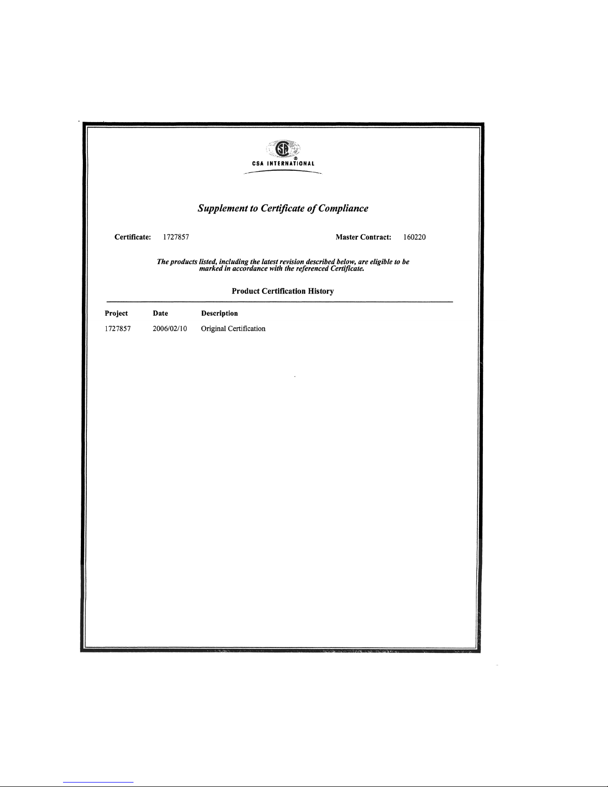
57
CSA - Approval
CSA - Approval
Page 58
CSA - Approval
58
Page 59
59
CSA - Approval
Page 60

Declaration of Conformity
60
Declaration of Conformity
Page 61

Page 62

Page 63

Page 64

90 23 974 - GA 4677.500 en
© Dräger Safety AG & Co. KGaA
Edition 10 - February 2016 (Edition 01 - December 2005)
Subject to alteration
Dräger Safety AG & Co. KGaA
Revalstraße 1
D-23560 Lübeck
Germany
Phone +49 451 8 82 - 27 94
Telefax +49 451 8 82 - 49 91
www.draeger.com
 Loading...