

Page 1
ÉQUIPEMENT DOYON INC.
1255, rue Principale
Linière, Qc, Canada G0M 1J0
Tel.: 1 (418) 685-3431
Canada: 1 (800) 463-1636
US: 1 (800) 463-4273
FAX: 1 (418) 685-3948
Internet: http://www.doyon.qc.ca
e-mail: doyon@doyon.qc.ca
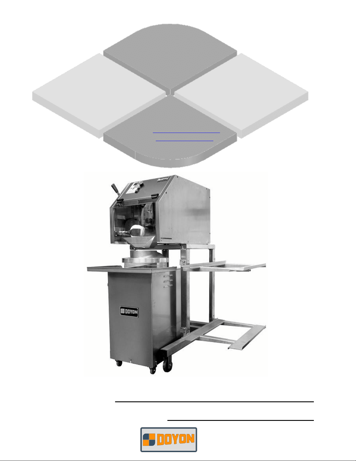
XXXX
Product / Produit:
Serial number / Numéro de série:
Page 2

IMPORTANT SAFETY INSTRUCTIONS
SAVE THESE INSTRUCTIONS
DANGER
TO REDUCE THE RISK OF FIRE OR ELECTRIC SHOCK
CAREFULLY FOLLOW THESE INSTRUCTIONS
TABLE OF CONTENTS
(table des matières :page suivante)
DESCRIPTION________________________________________________________________ A-1
Reception of the merchandise__________________________________________________ A-1
Nameplate _________________________________________________________________ A-1
Warnings__________________________________________________________________ A-3
Technical characteristics______________________________________________________ A-5
Installation ________________________________________________________________ A-7
Use of the machine _________________________________________________________ A-11
Cleaning and maintenance ___________________________________________________ A-17
COMPONENT PARTS __________________________________________________________B-1
DD10______________________________________________________________________B-1
DR45 ______________________________________________________________________B-5
DD10 - DR45 [LIVRET].doc 06/10
Page 3

IMPORTANT INSTRUCTIONS DE SÉCURITÉ
CONSERVEZ CE MANUEL D’INSTRUCTIONS
DANGER
AFIN DE RÉDUIRE LES RISQUES D'INCENDIE OU D'ÉLECTROCUTION
SUIVRE CES INSTRUCTIONS AVEC SOIN
TABLE DES MATIÈRES
DESCRIPTION _________________________________________________________________A-2
Réception de la marchandise ___________________________________________________A-2
Plaque signalétique___________________________________________________________A-2
Avertissement _______________________________________________________________A-4
Caractéristiques techniques ____________________________________________________A-6
Installation _________________________________________________________________A-9
Utilisation des machines______________________________________________________A-14
Entretien et nettoyage ________________________________________________________A-21
PIÈCES COMPOSANTE _________________________________________________________B-1
DD10______________________________________________________________________B-1
DR45 ______________________________________________________________________B-5
Page 4

A-1
SECTION A:
DESCRIPTION
RECEPTION OF THE MERCHANDISE
CAUTION
READ ALL INSTRUCTIONS
Take care to verify that the received equipment is not damaged before signing the delivery receipt. If
a damage or a lost part is noticed, write it clearly on the receipt. If it is noticed after the carrier has
left, contact immediately the freight company in order that they do their inspection
We do not assume the responsibility for damages or losses that may occur during transportation.
For your safety, this equipment has been verified by qualified technicians and carefully crated before
shipment. The freight company assumes full responsibility concerning the delivery in good condition
of the equipment in accepting to transport it.
NAMEPLATE
Each machine has a nameplate fixed on the machine, with the general characteristics of the machine.
1- Serial number
2- Model
3- Date
4- Phase
5- Amperage
6- Voltage
7- Frequency
Page 5

A-2
DESCRIPTION
RÉCEPTION DE LA MARCHANDISE
AVERTISSEMENT
LIRE TOUTES LES INSTRUCTIONS
Avant de signer le reçu de livraison, prenez soin de vérifier dès la réception si l’équipement n’est
pas endommagé. Si un dommage ou une perte est détecté, écrivez-le clairement sur le reçu de
livraison ou votre bon de transport et faites signer le livreur. Si le dommage est remarqué après le
départ du transporteur, contactez immédiatement la compagnie de transport afin de leur permettre
de constater les dommages causés.
Nous ne pouvons assumer la responsabilité pour les dommages ou les pertes qui pourraient survenir
pendant le transport.
Pour votre protection, cet équipement a été vérifié et emballé avec précaution par des techniciens
qualifiés avant son expédition. La compagnie de transport assume la pleine responsabilité
concernant la livraison de cet équipement en bon état en acceptant de le transporter.
PLAQUE SIGNALÉTIQUE
Une plaque signalétique est fixée sur chaque appareil comportant les caractéristiques générales de
celle-ci soit :
1- Numéro de série
2- Modèle
3- Date
4- Phase
5- Ampérage
6- Voltage
7- Fréquence
Page 6

A-3
WARNINGS
Important safety instructions
Installation and service must be done by specialized technicians.
Contact a certified electrician for set-up.
Electrical supply installation must be in accordance with the electrical rating on the nameplate
The machine was designed to be used by qualified people in the pastry and bakery’s business.
Other uses will be considered improper.
The manufacturer is not responsible for any damages or personal injuries to improper use of
the machine.
Page 7

A-4
AVERTISSEMENT
Instructions de sécurité importantes
L’installation et le service doivent être effectués par un technicien spécialisé.
Contactez un technicien spécialisé en électricité.
L’installation électrique doit être effectuée conformément à celui spécifié sur la plaque
signalétique.
Cet appareil a été conçu afin d’être opéré par un personnel qualifié du domaine de la pâtisserie et
de la boulangerie.
Tout autre utilisation sera considéré inappropriée.
Le manufacturier ne peut être tenu responsable pour les dommages ou blessures causés par une
utilisation inappropriée de l’appareil.
Page 8
A-5
TECHNICAL CHARACTERISTICS
ROUNDER DR45
Body
Motor Power
Gearbox
Dough size capacity oz (g)
Hourly production (piece/h)
Machine Dimensions inch
(cm)
Machine Net Weight Lb
(kg)
[1]
Anti-wear gear oil, type SHELL CASSIDA FLUID GL, developed for the lubrication of
enclosed gears in food and beverage processing machinery. Registered by NFS (class H1) for
use where there is potential for incidental contact with food, this product meets the former
guidelines of the USDA FSIS.
Stainless steel
Single phase only:
120V, 6A, 60Hz 1HP
1700 rpm
or (optional)
220V, 3A, 1HP, 50 Hz
1400 rpm
[1]
Oil
3.5 to 36 (100 to 1000)
1800
13,3/4 x 21,1/4 x 31,1/2
(35 x 54 x 80)
196 (89)
DIVIDER-ROUNDER DD10 divider DD10 + DR45 divider
rounder combo
Body
120V, 10A, 1.25HP, 60Hz,
Motor Power
Stainless steel Stainless steel
Single phase:
Single phase:
120V, 10A, 1.25HP, 60Hz
or (optional)
220V, 5A, 1HP, 50Hz
120V, 6A, 1HP, 60Hz
and
Or (optional)
220V, 1PH, 50Hz
Gearbox
Dough size capacity oz (g)
Maximum dough per hour
[1]
Oil
1 to 28 (20 to 800) 3.5 to 28 (100 to 800)
850 (336) 850 (336)
Oil
[1]
production Lbs (Kg)
Machine Dimensions inch
(cm)
Machine Net weight Lbs
30 ¾ x 17 x 18 ½
(78 x 43 x 47)
112 (51) 352 (160)
20 ½ x 31 ½ x 53 ¼
(52 x 80 x 135)
(kg)
Upper tank capacity Lbs
88 (40) 88 (40)
(kg)
Page 9
A-6
CARACTÉRISTIQUES TECHNIQUES
Bouleuse DR45
Construction
Force du Moteur
Boîte de vitesse
Capacité de pâte oz (g)
Production (piece/h)
Dimensions de l’appareil
pouce (cm)
Poids de l’appareil Lbs (kg)
[1] Huile de vitesse anti-usure, type SHELL CASSIDA FLUID GL, développée pour la
lubrification des appareils utilisés pour le domaine alimentaire. Enregistré par NFS (class
H1) pour l’utilisation ayant un contact potentiel avec la nourriture, ce produit rencontre les
anciennes normes de l’USDA FSIS.
Acier inoxydable
Simple phase seulement:
120V, 6A, 60Hz 1HP
1700 rpm
or (optionnel)
220V, 3A, 1HP, 50 Hz
1400 rpm
[1]
Huile
3.5 à 36 (100 à 1000)
1800
13,3/4 x 21,1/4 x 31,1/2
(35 x 54 x 80)
196 (89)
DIVISEUSE-BOULEUSE DD10 diviseuse DD10 + DR45 Combo
diviseuse bouleuse
Construction
Force du Moteur
Acier Inoxydable Acier Inoxydable
Simple phase:
120V, 10A, 1.25HP, 60Hz,
Simple phase:
120V, 10A, 1.25HP, 60Hz
ou (optionnel)
220V, 5A, 1HP, 50Hz
120V, 6A, 1HP, 60Hz
et
Ou (optionnel)
220V, 1PH, 50Hz
Boîte de vitesse
Capacité de pâte oz (g)
Production maximale en
[1]
Huile
1 à 28 (20 à 800) 1 à 28 (20 à 800)
850lbs (336Kg) de pâtes 850lbs (336Kg) de pâtes
Huile
[1]
Lbs (Kg) par heure
Dimensions de l’appareil
pouce (cm)
Poids de l’appareil Lbs (kg)
Capacité du réservoir
30 ¾ x 17 x 18 ½
(78 x 43 x 47)
112 (51) 352 (160)
88 (40) 88 (40)
20 ½ x 31 ½ x 53 ¼
(52 x 80 x 135)
supérieur Lbs (kg)
Page 10

A-7
INSTALLATION
Installation must be done by specialized technicians. Contact a certified electrician for set-up.
ATTENTION : Electrical supply installation must be in accordance with the electrical rating on the
nameplate.
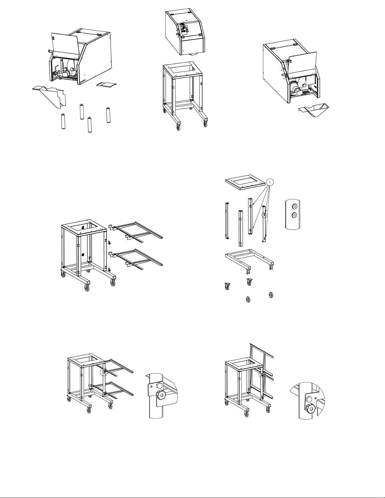
1. TROLLEY INSTALLATION
• Take out trolley’s components from the package, pay attention not to lose wheels and screws.
• Assemble the trolley, pay attention to the position of the two legs with inserts (see enclosures,
Fig. 17, n°1).
2. SHELVES INSTALLATION
• All trolleys are predisposed to be assembled with two shelves (optional).
• Take out the shelves components from the package, pay attention not to lose screws.
• Assemble shelves by using the proper screws and nuts (Fig. 18).
• Shelf in open position, fasten the nuts as in Fig. 19.
• Shelf in closed position, fasten the nuts as in Fig. 20.
3. DIVIDER DD10 INSTALLATION
• Assemble the components that are in the tank as follow :
• MACHINE FOR BENCH:
-Assemble the four legs, the chute and the door for the pasta’s outlet (Fig. 14).
ATTENTION : The chute and the door for the pasta’s outlet are safety devices provided
with a sensor. If there aren’t these devices or they are badly installed the machine can’t work.
• MACHINE WITH ROUNDER
-Fix the machine to the trolley by using the four proper screws (Fig. 15).
-Assemble the funnel (Fig. 16)
Page 11

A-8
ATTENTION : The funnel is a safety device provided with a sensor. If there isn’t this
device or it is badly installed, the machine can’t work.
• Place the machine on a floor where there is ample space and which is perfectly leveled, dry and
stable possibly away from sources of heat and from water taps.
• Make sure the specifications on the nameplate correspond to the electricity tension on the work
premises (Fig. 1).
• Ensure that the tank is free from any kind of objects (Fig. 2).
• Ensure that the screw feeder at the bottom of the tank is in place and that the nut at the back of
the machine is tightly fastened (Fig. 3).
• Periodically check the state of wear of the wires and electrical parts.
4. ROUNDER DR45 INSTALLATION
• Assemble the wheels: the front ones are WITH the brake (Fig. 22, n°1) and the rear ones are
WITHOUT (Fig. 22, n°2).
• Assemble the lid and the tray out of balls (Fig. 26).
• ATTENTION :The lid and the tray are safety devices provided with a sensor. If there aren’t
these devices or they are badly installed the machine can’t work.
• Place the machine on a floor where there is ample space and which is perfectly leveled, dry and
stable, possibly away from sources of heat and from water taps.
• Make sure the specifications on the nameplate correspond to the electricity tension on the work
premises (Fig. 21).
• Ensure that the hole for the pasta’s entry is free from any kind of objects (Fig.23).
Periodically check the state of wear of the wires and electrical parts.
Page 12

A-9
INSTALLATION
L’installation doit être effectuée par un technicien spécialisé. Contactez un technicien spécialisé en
électricité.
ATTENTION : L’installation électrique doit être effectuée conformément à celui spécifié sur la
plaque signalétique.
1. INSTALLATION DU CHARIOT
• Sortez les composantes du chariot de l’emballage en portant attention à ne pas perdre les roues
et les vis.
• Assemblez le chariot en portant attention à la position des deux pattes avec insertions (voir
dessins, Fig. 17, n°1).
2. INSTALLATION DES TABLETTES
• Tous les chariots sont prédisposés à être assemblés avec deux tablettes (optionnel).
• Sortez les composantes des tablettes de l’emballage en portant attention à ne pas perdre les vis.
• Assemblez les tablettes en utilisant les vis et les écrous appropriés (Fig. 18).
• Tablette en position ouverte : assemblez les écrous comme à la Fig. 19.
• Tablette en position fermée : assemblez les écrous comme à la Fig. 20.
3. INSTALLATION DE LA DIVISEUSE DD10
• Assemblez les composantes qui sont dans le réservoir comme suivant :
• INSTALLATION POUR LE COMPTOIR:
-Assemblez les quatre pattes, la chute et la porte pour la sortie des pâtes (Fig. 14).
ATTENTION : La chute et la porte pour la sortie des pâtes sont des dispositifs de sécurité
équipés de sonde. S’il n’y a pas ces dispositifs ou si ceux-ci sont mal installés, l’appareil ne
peut fonctionner.
• INSTALLATION AVEC LA BOULEUSE
-Fixez l’appareil au chariot en utilisant les 4 vis appropriées (Fig. 15).
-Assemblez l’entonnoir (Fig. 16).
Page 13

A-10
ATTENTION : L’entonnoir est un dispositif de sécurité équipé d’une sonde. Si ce dispositif
manque ou est mal installé, l’appareil ne peut fonctionner.
• Placez la machine sur un plancher ou l’espace y est suffisant et qui est parfaitement nivelé, sec
et à l’abri des sources de chaleur et des robinets.
• Assurez-vous que la tension sur les lieux de travail correspond à celle mentionnée sur la plaque
signalétique (Fig. 1).
• Assurez-vous que le réservoir est exempt de tous objets pouvant l’obstruer (Fig. 2).
• Assurez-vous que la vis d’alimentation au fond du réservoir est en place et que l’écrou au fond
de la machine est bien serré (Fig. 3).
• Vérifiez périodiquement l’état d’usure des fils et des pièces électriques.
4. INSTALLATION DE LA BOULEUSE DR45
• Assemblez les roues : celles de devant ont un frein (Fig. 22, n°1) celles de derrière n’en ont pas
(Fig. 22, n°2).
• Assemblez le couvercle et le plateau de sortie des boules de pâte (Fig. 26).
• ATTENTION :Le couvercle et le plateau de sortie sont des dispositifs de sécurité équipés de
sondes. Si ces dispositifs manques ou sont mal installés, la machine ne peut fonctionner.
• Placez la machine sur un plancher ou l’espace y est suffisant et qui est parfaitement nivelé, sec
et à l’abri des sources de chaleur et des robinets.
• Assurez-vous que la tension sur les lieux de travail correspond à celle mentionnée sur la plaque
signalétique (Fig. 21).
• Assurez-vous que le trou pour l’entrée des pâtes est exempt de tous objets pouvant l’obstruer
(Fig.23).
• Vérifiez périodiquement l’état d’usure des fils et des pièces électriques.
Page 14

A-11
USE OF THE MACHINE
1. USE OF THE DIVIDER DD10
ATTENTION
Electronic Divider mod. DD10 is a machine able to produce a range of portions from 0.7 oz (20 g) to
28 oz (800 g). The combined or separately use of timer and mechanical feeler pin is like to have two
machines in one: this machine is able to make the same work made before from two different
machines.
CONTROL PANEL LEGEND
• Display for TIMER and ALARM CODES (Fig. 4, n°1)
• Timer regulation with RELIEF-BUTTONS (Fig. 4, n°2)
• LED to indicate the work selected function: TIMER (Fig. 4,n°3)
• LED to indicate the work selected function MECHANICAL FEELER PIN (Fig.4, n°4)
• LED to indicate the work selected function TIMER + MECHANICAL FEELER PIN (Fig.4,
n°5)
• Relief button to RESET the machine (Fig.4, n°6)
• Relief button (Fig.4, n°7) to select a WORK FUNCTION (Fig.4, n°3,4,5)
• Alarm code LEGEND (Fig. 4,n°8)
• EMERGENCY button (Fig. 4, n°9)
• START button (Fig. 4,n°10)
• STOP button (Fig. 4, n°11)
• FEELER PIN control lever (Fig.6)
STARTING OF THE DIVIDER
• Make sure that the emergency button (Fig. 4, no°9) is released, turn it clockwise.
• Close the doors of the machine. Once they are closed, the display (Fig. 4, n°1) indicates an
alarm code and in this situation the green Start button is deactivated (Fig.4, n°10).
• Push the red Stop button (Fig. 4, n°11) or the Reset button (Fig. 4, n°6) to delete the alarm codes
indicated on the display.
• Push the green Start button (Fig.4, n°10) to start the machine (green led lighted).
INSERTION OF THE DOUGH
Open the upper door and put the dough, about 40 kg, in the tank (Fig.7)
Close the door and start the machine.
ATTENTION : completely fill the tank to obtain equal portions of pasta.
Page 15
A-12
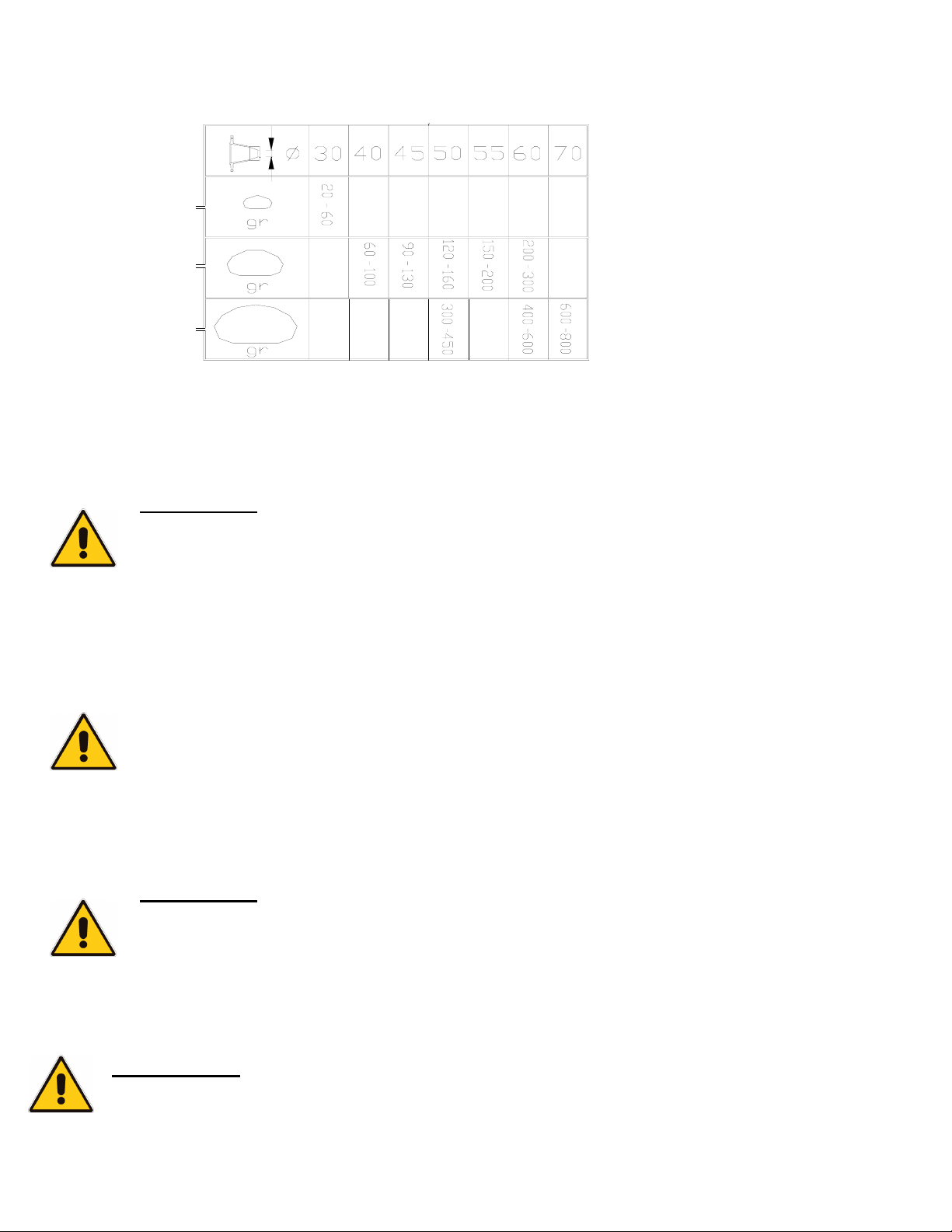
EXAMPLE FOR DOUGH WITH HUMIDITY FROM 50% TO 55% WITH FLOUR W 320
ADJUSTMENT OF PASTA PIECE SIZE
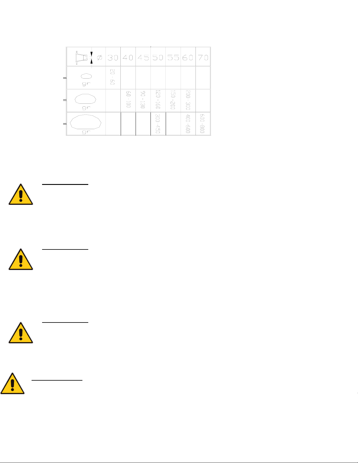
Check if the cone has the right diameter by referring to the cone table.
• Portion from 0.7 to 2.1oz (20 g to 60 g)
1. Select and insert a cone.
2. Choose with relief mode button (Fig. 4, n°7) the icon with a clock, light on (Fig. 4, n°3), and
regulate time of timer by correspondent buttons (Fig. 4, n°2)
ATTENTION :
When two or three pieces of pasta has emerged, turn off the machine and check the weight of the
last ball who came out. Any differences in weight should be corrected with the timer buttons
(Fig. 4, n°2). Repeat the operation until the right weight is obtained. Pieces of pasta of wrong
weight can be put back into the tank.
• Portion from 2.1 to 10.5 oz (60 g to 300g)
1. Select and insert a cone
2. Choose with relief mode button (Fig.4, n°7) the icon with mechanical lever, light on (Fig. 4, n°4)
ATTENTION :
When two or three pieces of pasta has emerged, turn off the machine and check the weight of the
last ball who came out. Any differences in weight should be corrected with the feeler adjustment
lever (Fig. 6). Repeat the operation until the right weight is obtained. Pieces of pasta of wrong
weight can be put back into the tank. To obtain equal portions of pasta, the cone must have a
diameter as big as the distance of the feeler pin from the same cone.
• Portion from 10.5 to 28 oz (300 g to 800 g)
1. Select and insert a cone
2. Choose with relief mode button (Fig. 4, n°7)
ATTENTION :
When two or three pieces of pasta has emerged, turn off the machine and check the weight of the
last ball who came out. Any differences in weight should be corrected with the feeler adjustment
lever (Fig. 6) or with the relief buttons (Fig.4, n°2). Repeat the operation until the right weight is
obtained. Pieces of pasta of wrong weight can be put back into the tank.
IMPORTANT
In case of alarm signal, the divider stop to work automatically.
Take a look to the display (Fig. 4, n°1) to see which kind of alarm it is. When the problem is
resolved, push the Reset button or push Start button and the divider will restart.
Page 16

A-13
CODE
ALLARM
A0 KNIFE BLOCKED Check if knife is right insert
A1 FRONT DOOR OPEN Close the door
A2 UPPER DOOR OPEN Close the door
A3 SLIDE MISSING Insert slide or check its right
A4 DOUGH EXIT OPEN Install exit dough exit or
A5 OVERHEATED ENGINES Let stop divider for 10-15 min.
A6 FEELER PIN BLOCKED Feeler pin lever non correctly
DESCRIPTION POSSIBLE SOLUTION
and verify that any external
object could stop the complete
knife-rotation.
position
check its right position
ca. and restart. If engine
overheating occurs frequently,
contact the assistance point.
insert or lever non correctly
blocked
2. USE OF THE ROUNDER DR45
• Check if the lid and the tray are correctly assembled (Fig. 26).
• Check if the central feeder screw lets the pasta fall on the tray. If it isn’t right, lift the central
feeder screw, turn it of 180° and put it down in its slots (Fig. 25).
• Make sure that the emergency button (fig. 24, n°2) is released, turn clockwise.
• Push the green Start button (fig. 24, n°1) to start the machine.
• Put the portion of pasta in the central hole of the central feeder screw (fig. 23)
• Put the next portion of pasta after approximately 1,5 seconds.
ATTENTION : Don’t put dry portions of pasta on dry external surface
• The little balls perfectly rounded fall on the machine’s tray.
• The worker must only take the little balls from the tray and position them in the boxes fir the
leavening.
The machine is tested with dough with humidity from 50% to 55%.
Page 17

A-14
UTILISATION DES MACHINES
1. UTILISATION DE LA DIVISEUSE DD10
La diviseuse modèle DD10 est une machine pouvant produire des portions de 0.7 oz (20g) à 28 oz
(800g).
PANNEAU DE CONTRÔLE
Figure 4
• Point 1 : Panneau de la minuterie et des codes de l’alarme
• Point 2 : Minuterie régulateur avec boutons de relâche. (Fig. 4, n°2)
• DEL pour indiquer la sélection de fonction.: MINUTERIE (Fig. 4,n°3)
• DEL pour indiquer l’opération déterminée par la minuterie. (Fig.4, n°4)
• DEL pour indiquer la sélection déterminée par MINUTERIE + MODE MÉCHANIQUE (Fig.4,
n°5)
• Bouton pour éliminer une alarme. (Fig.4, n°6)
• Bouton (Fig.4, n°7) pour sélectionner les fonctions. (Fig.4, n°3,4,5)
• Point 8 : Légende des codes d’alarme
• Point 9 : Bouton d’Urgence
• Point 10 : Touche de démarrage
• Point 11 : Touche d’arrêt
• Levier pour contrôler la grosseur de boule mécaniquement. (Fig.6)
DÉMARRAGE
• Vérifier si le bouton d’urgence est déclenché (Fig. 4, no°9), tourner dans le sens des aiguilles
d’une monte.
• Fermer les portes de la machine.. Une fois fermées, l’affichage Fig. 4, n°1) indique un code
d’alarme (et dans cette situation le bouton de démarrage vert est désactivé. (Fig.4, n°10).
• Enfoncer le bouton d’arrêt (Fig. 4, n°11) ou le bouton de redémarrage (Fig. 4, n°6) pour effacer
les codes d’alarme indiqués sur l’affichage.
• Enfoncer le bouton de démarrage vert (Fig.4, n°10) pour démarrer la machine (Del vert allumé).
AJOUT DE LA PÂTE
Ouvrir le pore supérieur et mettre approximativement 40Kg de pâte dans le réservoir. (Fig.7)
Fermer la porte et démarrer la machine.
.ATTENTION : Remplir complètement le réservoir afin d’obtenir des portions identiques de pâtes.
Page 18
A-15
EXEMPLE DE PÂTES AVEC HUMIDITÉ DE 50% À 55% AVEC FARINE W320
AJUSTEMENT DE LA GROSSEUR DES BOULES DE PÂTES
Vérifier si les cônes ont les bonnes mesures de diamètre en vous référant à la grille ci bas.
• Portion de 0.7 to 2.1oz (20 g to 60 g)
3. Choisir et insérer le cône.
4. Choisir la fonction sur les boutons de sélections. (Fig. 4, n°7) Lumière de l’icône de minuterie
est allumée (Fig. 4, n°3), Régler le temps de la minuterie avec les boutons correspondants. (Fig.
4, n°2)
ATTENTION :
Lorsque deux ou trois boules de pâte ont sorti, arrêter la machine et vérifier le poids de cette
dernière. S’il y a différence de poids, elle devrait être corrigée avec le bouton de minuterie.
(Fig. 4, n°2). Répéter l’opération jusqu'à l’obtention du bon poids. Les boules avec le mauvais
poids peuvent être remises dans le réservoir.
• Portion de 2.1 to 10.5 os (60 g to 300g)
3. Choisir et insérer le cône.
4. Choisir la fonction sur les boutons de sélections (Fig.4, n°7) La lumière de fonction de la
minuterie est allumée. (Fig. 4, n°4)
ATTENTION
Lorsque deux ou trois boules de pâte ont sorti, arrêter la machine et vérifier le poids de cette
dernière. S’il y a différence de poids, elle devrait être corrigée avec le bouton de minuterie.
(Fig. 6). Répéter l’opération jusqu'à l’obtention du bon poids. Pour obtenir des boules de pâte
de poids identiques, le diamètre du cône devrait être aussi gros que la distance du capteur sur le
même cône.
• Portion de 10.5 to 28 oz (300 g to 800 g)
3. Choisir et insérer le cône
4. Choisir la fonction sur les boutons de sélections (Fig. 4, n°7)
ATTENTION :
Lorsque deux ou trois boules de pâte ont sorti, arrêter la machine et vérifier le poids de cette
dernière. S’il y a différence de poids, elle devrait être corrigée avec le bouton de minuterie.
(Fig. 4, n°2). Répéter l’opération jusqu'à l’obtention du bon poids. Les boules avec le mauvais
poids peuvent être remises dans le réservoir.
IMPORTANT
En cas de signal d’alarme, la diviseuse arrête de fonctionner automatiquement.
Vérifier quel alarme il s’agit sur le panneau. (Fig. 4, n°1) Lorsque le problème est résolu, presser
le bouton de redémarrage ou le bouton de démarrage et la diviseuse se remettra à fonctionner.
Page 19

A-16
CODE
ALARME
A0 BLOCAGE DE COUTEAU Vérifier si le couteau est bien
A1 PORTE AVANT OUVERTE Fermer la porte
A2 PORTE SUPÉRIEURE
A3 CHUTE MANQUANTE Insérer la chute ou vérifier sa
A4 LA SORTIE DE LA PÄTE EST
A5 SURCHAUFFAGE DU
A6 BLOCAGE DU CAPTEUR Le capteur n’est pas installé
DESCRIPTION POSSIBLE SOLUTION
inséré et qu’il n’a pas d’objets
qui peuvent arrêter
complètement la rotation du
couteau.
OUVERTE
Installer la sortie de la pâte ou
OUVERTE
MOTEUR
surchauffage du moteur arrive
correctement ou le levier n’est
Fermer la porte
position.
vérifier sa position.
Arrêter la diviseuse 10-15
min. et redémarrer. Si le
fréquemment, appeler le
service.
pas bloqué correctement.
2. UTILISATION DE LA BOULEUSE DR45
• Vérifier si le couvercle et le plateau sont assemblés correctement. (Fig. 26).
• Vérifier si les vis de l’alimentation centrale laisse les boules de pâte tomber sur le plateau. Si ce
n’est pas correct, soulever la vis de l’alimentation centrale, l’arrêter à 180° et le déposer dans
les rainures. (Fig. 25).
• Soyez certain que le bouton d’urgence (fig. 24, n°2) est relâché, tourner dans le sens des
aiguilles d’une montre.
• Peser sur bouton de démarrage vert (fig. 24, n°1) pour mettre en marche la machine.
• Mettre une portion de pâte dans l’orifice central de la vis d’alimentation. (fig. 23)
• Après 1,5 seconds, insérer une autre portion de pâtes.
ATTENTION : Ne pas mettre de portions de pâtes sèches sur une surface extérieure sèche.
• Les petites boules parfaitement rondes tombent sur le plateau de la machine.
• Le travailleur doit prendre les petites boules du plateau et le positionner dans les boîtes pour les
faire lever.
La machine est vérifiée avec une pâte au taux d’humidité de 50% à 55%.
Page 20

A-17
CLEANING AND MAINTENANCE
ATTENTION
• Before doing any maintenance or cleaning, make sure to turn off the main switch and that the
power supply plug is disconnected.
• After every running of the machine, it should be cleaned to ensure a correct functioning and to
keep the machine in good condition.
• The machine may be cleaned with normal neutral detergents who do not contains soda.
• Do not clean the machine with a jet of water.
• It isn’t possible to wash the removable parts in a dishwashing machine.
• The divider’s doors are made in a special plastic transparent, do not use alcohol to clean this
material
The following instructions must be scrupulously followed when the machine is cleaned:
1. CLEANING AND MAINTENANCE DIVIDER DD10
1. Take off the plug out of the socket.
2. As in Fig. 8, open the front door.
3. As in Fig. 9, extract the axis of the feeler pin (number 1) and then remove the feeler pin (number
2).
4. As in Fig. 10, unscrew the nut (number 1) and extract the knife (number 2).
5. As in Fig. 16, extract the chute or the funnel.
6. As in Fig. 11, remove the extrusion cone, unscrewing the two nuts.
7. As in Fig. 12, unscrew the nut at the back of the machine (fig. 3) completely and extract the
central tube.
8. As in Fig. 13, extract the feeder screw.
2. CLEANING AND MAINTENANCE ROUNDER DR45
1. Take off the plug out of the socket;
2. As in Fig. 26, remove the tray and the lid;
3. As in Fig. 27, remove the central feeder screw with a direct pull;
4. As in Fig. 28, rotate the plastic cylinder extracting it vertically;
5. As in Fig. 29, extract from inside the plate support;
6. Clean all with warm water and brush;
7. Reassemble all the parts in the opposite order.
Page 21

Fig. 1 Fig.2 Fig. 3
A-18
Fig. 4
Fig. 8 Fig. 9
Fig. 5 Fig. 6
Fig. 10
Fig. 11 Fig. 12 Fig. 13
Page 22

A-19
Fig. 14 Fig. 15
Fig. 17 Fig. 18
Fig. 16
Fig. 19 Fig. 20
Page 23

Fig. 21 Fig. 22 Fig. 23
A-20
Fig. 26Fig. 25Fig. 24
Fig. 29Fig. 28Fig. 27
Page 24

A-21
ENTRETIEN ET NETTOYAGE
ATTENTION
• Avant de faire l’entretien ou le nettoyage, fermer l’alimentation principale et débrancher de
l’alimentation électrique.
• Après chaque utilisation de l’unité, elle devrait être nettoyée pour assurer le bon fonctionnement
et la garder en bonne condition.
• La machine peut être nettoyée avec un détergent ordinaire neutre qui ne contient pas de soda.
• Ne pas nettoyer le machine avec un jet d’eau..
• C’est pas possible de laver pièces détachables dans le lave vaisselle. .
• Les portes de la diviseuse sont fait de plastique spécial transparent, ne pas utiliser d’alcool pour
nettoyer.
• Les instructions suivantes doivent être suivies à la lettre lors du nettoyage de la machine :
1. NETTOYAGE ET ENTRETIEN DE LA DIVISEUSE DD10
9. Débrancher de l’interrupteur.
10. Ouvrir la porte Fig. 8.
11. Retirer l’axe de la broche du capteur (numéro 1) et ensuite enlever la broche du capteur
(numéro 2). Fig. 9,
12. Dévisser l’écrou (numéro 1) et extraire le couteau (numéro 2). Fig. 10.
13. Enlever la chute. Fig. 16
14. Enlever le cône d’extrusion, dévisser les deux écrous. Fig. 11
15. Dévisser complètement l’écrou a l’arrière de la machine (fig. 3) et enlever le tube central.
Fig. 12
16. Retirer la vis de l’alimentation. Fig. 13
2. NETTOYAGE ET ENTRETIEN DE LA BOULEUSE DR45
8. Débrancher l’appareil de l’interrupteur.
9. Enlever le couvercle et le plateau. Fig. 26
10. En tirant, enlever la vis de l’alimentation centrale. Fig. 27
11. En le retirant verticalement, faire la rotation du cylindre en plastique. Fig. 28
12. Enlever de l’intérieur, le support du plateau. Fig. 29
13. Nettoyer avec de l’eau tiède et une brosse.
14. Ré assembler tous les pièces en suivant a l’inverse les indications mentionnées ci haut.
Page 25

Fig. 1 Fig.2 Fig. 3
A-22
Fig. 4
Fig. 8 Fig. 9
Fig. 5 Fig. 6
Fig. 10
Fig. 11 Fig. 12 Fig. 13
Page 26
A-23
Fig. 14 Fig. 15
Fig. 17 Fig. 18
Fig. 16
Fig. 19 Fig. 20
Page 27

Fig. 21 Fig. 22 Fig. 23
A-24
Fig. 26Fig. 25Fig. 24
Fig. 29Fig. 28Fig. 27
Page 28

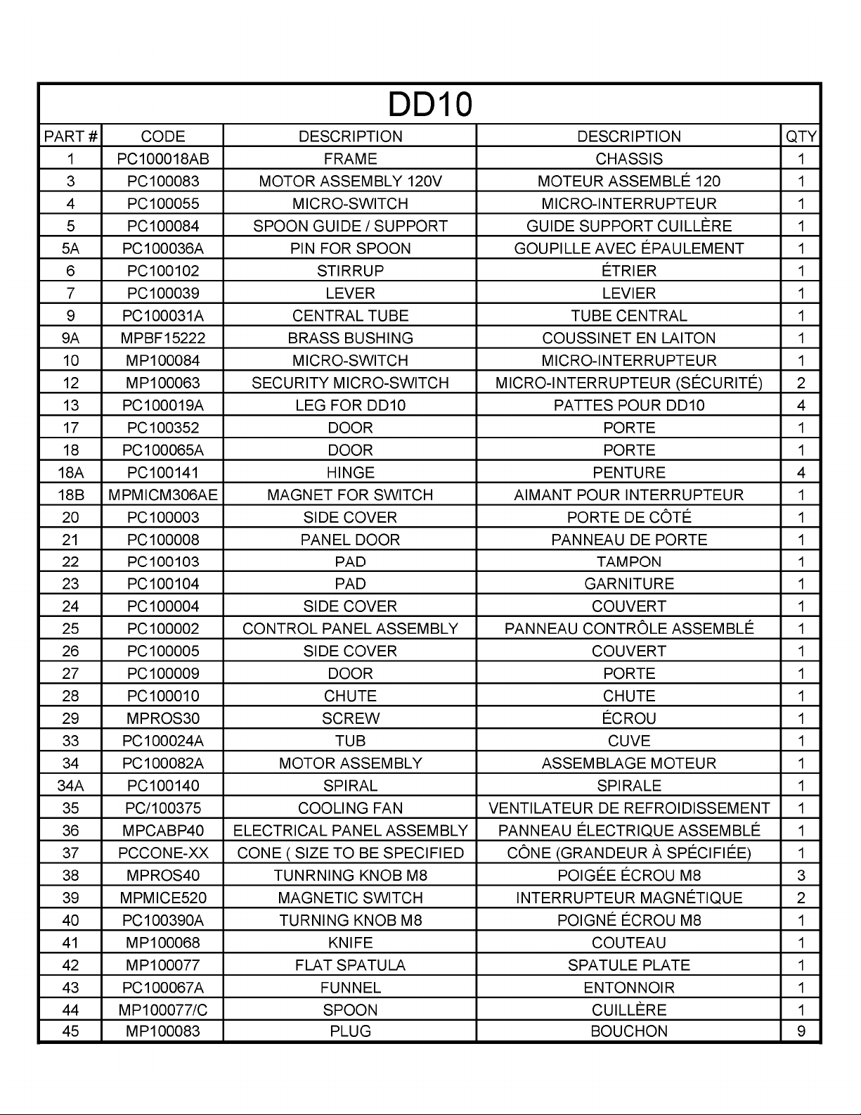
B-1
B-1
SECTION B:
COMPONENT PARTS
PIÈCES COMPOSANTE
DD10
DD10
Page 29
B-2
B-2
Page 30

B-3
B-3
Page 31

B-4
B-4
Page 32

B-5
B-5
DR45
DR45
Page 33

B-6
Page 34

B-7
NOTES
Page 35

Page 36

NOTES
Page 37

Page 38

LIMITED WARRANTY
(Continental United States Of America And Canada Only)
Doyon Equipment Inc. guarantees to the original purchaser only that its product are
free of defects in material and workmanship, under normal use.
This warranty does not cover any light bulbs, thermostat calibration or defects due to
or resulting from handling, abuse, misuse, nor shall it extend to any unit from which
the serial number has been removed or altered, or modifications made by
unauthorised service personnel or damage by flood, fire or other acts of God. Nor will
this warranty apply as regards to the immersion element damaged by hard water.
The extent of the manufacturer’s obligation under this warranty shall be limited to the
replacement or repair of defective parts within the warranty period. The decision of
the acceptance of the warranty will be made by Doyon Equipment service
department, which decision will be final.
The purchaser is responsible for having the equipment properly installed, operated
under normal conditions with proper supervision and to perform periodic preventive
maintenance.
If any parts are proven defective during the period of one year from date of purchase,
Doyon Equipment Inc. hereby guarantees to replace, without charge, F.O.B. Linière,
Quebec, Canada, such part or parts.
Doyon Equipment Inc will pay the reasonable labour charges in connection with the
replacement parts occurring within one year from purchase date. Travel over 50
miles, holiday or overtime charges are not covered. After one year from purchase
date, all labour and transportation charges in connection with replacement parts will
be the purchaser’s responsibility.
Doyon Equipment Inc. does hereby exclude and shall not be liable to purchaser for
any consequential or incidental damages including, but not limited to, damages to
property, damages for loss of use, loss of time, loss of profits or income, resulting
from any breach or warranty.
In no case, shall this warranty apply outside Canada and continental United States
unless the purchaser has a written agreement from Doyon Equipment Inc.
Page 39

GARANTIE LIMITÉE
(Pour le Canada et les États continentaux des États-Unis)
Équipement Doyon Inc. garantit ses produits à l'acheteur original, contre tout défaut
de matériaux ou de fabrication, en autant qu'ils aient été utilisés de façon normale.
Cette garantie ne s'applique cependant pas sur les ampoules, les calibrations de
température, tout défaut dû ou résultant d'une mauvaise manipulation, d'un emploi
abusif ou d'un mauvais usage. La garantie ne s'applique pas non plus sur tout
équipement dont le numéro de série aurait été enlevé ou altéré, tout produit modifié
par du personnel de service non autorisé, endommagé par une inondation, un feu ou
tout autre acte de Dieu, ni sur les éléments immergés endommagés par l'eau dure.
L'étendue des obligations du manufacturier, selon cette garantie, est le remplacement
ou la réparation des pièces défectueuses durant la période de garantie. L'acceptation
de la garantie sera faite par le département de service d'Équipement Doyon Inc.
Cette décision sera définitive.
L'acheteur est responsable de faire installer son équipement adéquatement, de
l'opérer sous des conditions normales d'utilisation avec une bonne supervision, ainsi
que d'effectuer un entretien préventif périodique.
Dans le cas où les pièces s'avéreraient défectueuses durant une période d'un an à
partir de la date d'achat, Équipement Doyon Inc. s'engage à les remplacer, sans
frais, F.O.B. Linière, Québec, Canada.
Équipement Doyon Inc. couvrira les frais raisonnables de main-d'œuvre reliés au
remplacement des pièces, pour une période d'un an à partir de la date d'achat.
Toutefois, les frais encourus pour les déplacements au-delà de 50 milles, le temps
supplémentaire et les jours de congé ne sont pas couverts. Au-delà d'un an après la
date d'achat, tous frais de transport et de main-d'œuvre pour le remplacement des
pièces sont la responsabilité de l'acheteur.
Équipement Doyon Inc. ne se tient pas responsable envers l'acheteur pour toutes
conséquences ou dommages incluant, mais non limités à, dommages à la propriété,
dommages pour perte d'usage, perte de temps, perte de profits ou de revenus,
provenant de tout bris de garantie.
En aucun cas, cette garantie ne s'applique à l'extérieur du continent des États-Unis
d'Amérique ou du Canada, à moins que l'acheteur n'ait une entente écrite avec
Équipement Doyon Inc.
Page 40

ÉQUIPEMENT DOYON INC.
1255, rue Principale
Linière, Qc, Canada G0M 1J0
Tel.: 1 (418) 685-3431
Canada: 1 (800) 463-1636
US: 1 (800) 463-4273
FAX: 1 (418) 685-3948
Internet: http://www.doyon.qc.ca
e-mail: doyon@doyon.qc.ca
 Loading...