

Page 1
USB Mobile Broadband Router
Reference Manual 7.1.5
The Mobile Choice for y our Broadb and Interne t
Page 2

Reference Manual 7.1.52
Table of Contents
Part 1
Part 2
Part 3
Introduction
................................................................................................................................... 41 Package contents
................................................................................................................................... 42 Access the router
................................................................................................................................... 53 Limited Internet Mode (L.I.M.)
................................................................................................................................... 54 Direct interface vs PPTP interface
Status Overview Bar
Menu System
................................................................................................................................... 71 HOME
................................................................................................................................... 72 INTERNET
................................................................................................................................... 103 MODEM
................................................................................................................................... 104 WAN
................................................................................................................................... 115 LAN
................................................................................................................................... 126 WLAN
................................................................................................................................... 147 VPN
................................................................................................................................... 158 SMS
................................................................................................................................... 179 NAS
................................................................................................................................... 1810 AUTOMATION
................................................................................................................................... 2011 POSITION
................................................................................................................................... 2012 SYSTEM
................................................................................................................................... 2213 UPGRADE
................................................................................................................................... 2314 RESTART
................................................................................................................................... 2315 LOGOUT
4
6
7
Part 4
Part 5
API
................................................................................................................................... 241 Enabling the API
................................................................................................................................... 242 Connecting to the API
................................................................................................................................... 243 Logging in to the API
................................................................................................................................... 244 API Syntax
................................................................................................................................... 255 Router info
................................................................................................................................... 256 Upgrade via API
................................................................................................................................... 267 SMS
................................................................................................................................... 288 Check services available
................................................................................................................................... 289 API Coding
Troubleshooting
................................................................................................................................... 291 Scenarios
................................................................................................................................... 302 Frequently Asked Questions
The Mobile Choice for y our Broadb and Interne t
24
29
© 2014 Dovado FZ-LLC
Page 3

3Contents
Part 6
Part 7
Support
Open Source Notice
................................................................................................................................... 331 GPL v2 Applications
................................................................................................................................... 372 GPL v3 Applications
................................................................................................................................... 433 LGPL Application
................................................................................................................................... 474 Mixed Licenses
33
33
The Mobile Choice for y our Broadb and Interne t
© 2014 Dovado FZ-LLC
Page 4
Reference Manual 7.1.54
1 Introduction
Thank you for choosing a Dovado USB Mobile Broadband Router. Dovado has quickly become the
leading brand in terms of support for 4G/LTE and 3G USB modems. Simply insert your compatible
USB modem into the Dovado router, and the two will be automatically paired in order to get you
online on the Internet. A well-known fact about Dovado is that it is quick to support new modems
and features, and provide you a smooth upgrade process with help of the DOVADO Firmware
Utility (Express Upgrader).
On every page in the router's User Interface, you will see this icon. Click it, and you will be
directed to the appropriate chapter in the reference manual automatically for further
information and guidance.
1.1 Package contents
Make sure all of the listed items below are included in your package. If something is missing, kindly
contact your reseller.
Router - USB Mobile Broadband router
Power supply
Quick Wizard Guide
2 x 3dBi antennas
USB extension cable
Additional required items:
In addition to the items above you will need a mobile broadband USB modem in order to connect to
a mobile network.
This modem provides the wireless link to your operator's network and is sold separately.
To use the Internet you need a computer.
1.2 Access the router
To access your router's menu system, connect your computer via WLAN or LAN port (with an
Ethernet cable) and access the http://192.168.0.1 website.
If you are connecting your computer via Wireless LAN, search for a wireless network called
"DOVADO-XXXXX", where XXXXX is a unique combination of characters. These details, along
with the passphrase, are available on a label on your router.
Once you have reached the login page, the information below is the default settings for your router:
Username: admin
Password: password
The Mobile Choice for y our Broadb and Interne t
© 2014 Dovado FZ-LLC
Page 5
1.3 Limited Internet Mode (L.I.M.)
Dovado routers support most Hi-Link (Huawei) and CWID (ZTE)-based USB modems. However,
unlike traditional USB modems, these specific models are designed to act as routers, imposing
certain limitations due to the complication of a second private network layer.
If you are in need any of the following capabilities, then please make sure to contact your operator
or reseller the router-based modem:
Limitations with Huawei Hi-Link modems:
UPnP, SMS and Bridge Mode cannot be used.
Port Forwarding is limited to a maximum total of 15 individual rule assignments.
The 192.168.1.x subnet cannot be occupied by the Dovado in conjunction with these modems, as
the Hi-Link device occupies this subnet.
Limitations with ZTE CWID modems:
UPnP and Bridge Mode cannot be used.
Port Forwarding does not work (at all) on certain models.
SMS is limited to certain models.
The 192.168.1.x subnet cannot be occupied by the Dovado router in conjunction with these
modems, as the Hi-Link device occupies this subnet.
Some modem models might already occupy 192.168.0.1, therefore requiring your Dovado router to
use a different subnet’s IP address, such as 192.168.2.1.
There exists at least three known combinations of capabilities when it comes to ZTE router-based
modems
Version 1: (USB modems)
SMS is available
Port Forwarding is not available
IP address cannot be changed on the USB modem, but might be required on Dovado router
Introduction 5
Version 2:(Mobile Hotspots devicesa and USB modem)
Port Forwarding is available
SMS is not available
Version 3: (Mobile Hotspots devices, not USB modem)
SMS is available
Port Forwarding is available
1.4 Direct interface vs PPTP interface
The Dovado router can have two IP Interfaces connected to the Internet: Direct Interface and
PPTP Interface. It is possible to access the router and clients behind it via both interfaces using
their IP addresses
Direct Interface this is the router's own interface which it normally uses to communicate on
the Internet
PPTP Interface this interface exists when a VPN PPTP service is used. When PPTP is used
the router has two IP addresses to the Internet.
Remote Management and Port forward notice
Not all Mobile Broadband operator, ISP and VPN providers allow external access to your router
from the Internet. If the provider blocks such access it is not possible to use Remote Management
or performing port forwards. Please contact your Internet Service Provider if you are having
problems with accessing the router from the Internet.
The Mobile Choice for y our Broadb and Interne t
© 2014 Dovado FZ-LLC
Page 6
Reference Manual 7.1.56
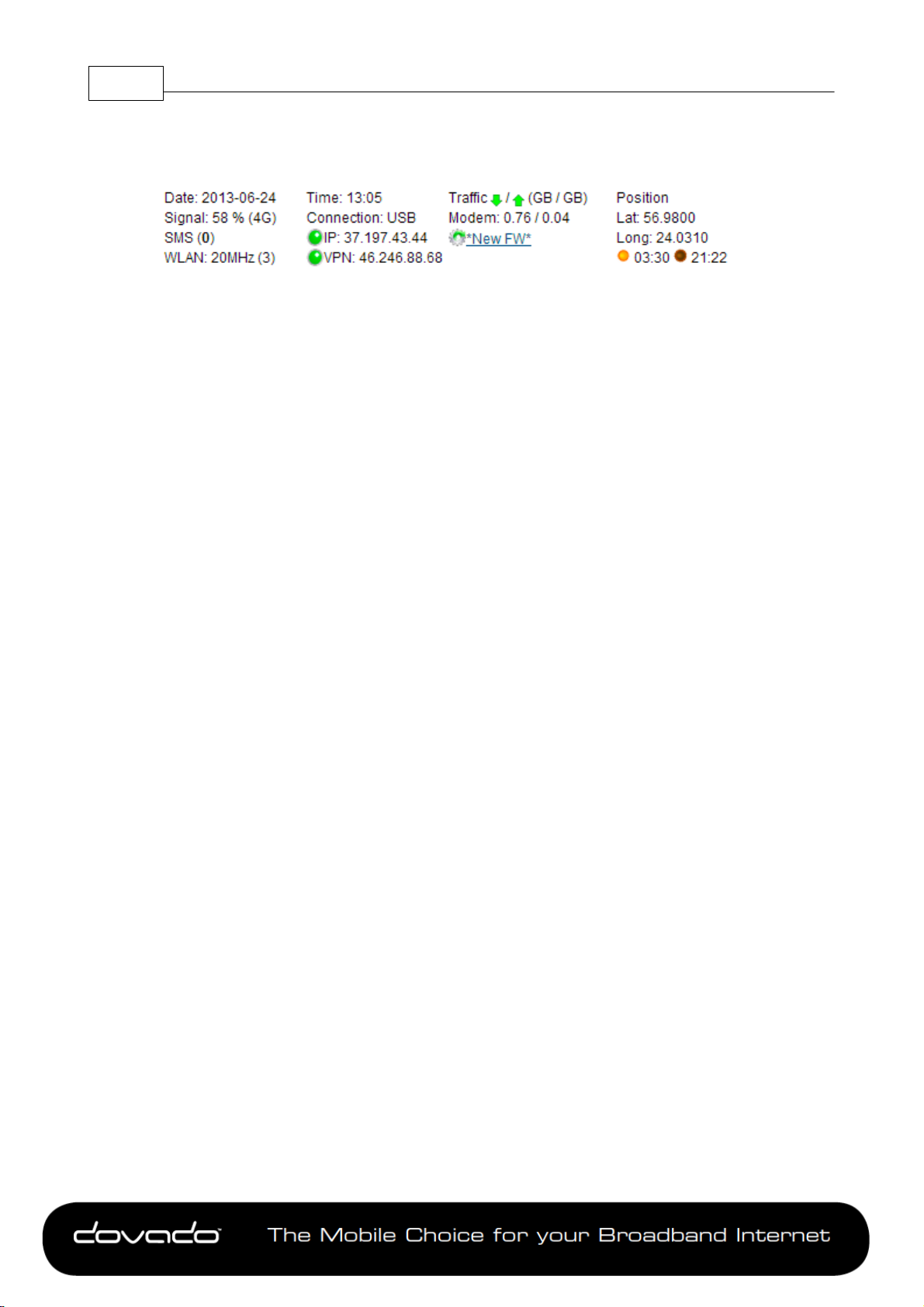
2 Status Overview Bar
Atop of the user interface, a bar displays an overview of your Internet connection.
This information sits outside the security zone of your router, and does not need to be accessed via
an authorized login, thus saving time on checking the connection status.
The Connection Status Overview Bar shows the following information:
Date: Synchronized with a Dovado NTP (Network Time Protocol) server upon each new successful
Internet connection.
Signal: The latest measurement gathered by the USB modem upon connection is displayed in a
percentage value, along with the technology (2G, 3G or 4G).
The value is only updated after initiating a new connection.
SMS: Shows the number of unread SMS's.
WLAN: Shows whether a 20 or 40MHz channel has been manually selected. The value within the
brackets indicates the channel(s) currently used.
Time: Displayed in a 24-hour format (HH:MM). In case the displayed time is incorrect, you can set
the time zone in the System->NTP page.
Connection: Indicates whether your current Internet connection is via the inserted USB modem or
via an Ethernet WAN port. This is useful if your router has been configured to perform automated
failovers between one dropped Internet connection to a secondary (backup) connection.
IP: Shows the IP address the router has received from your Internet/Mobile-broadband Service
Provider.
VPN: Show the IP address that the router has received from your VPN Service Provider
Connection Indicator: Green color indicates that the Dovado router is connected to the Internet
via a USB modem. Yellow color indicates that the router is connected Internet, but LAN and WiFi
clients is disable to access the Internet due to that scheduled event in the Internet Scheduler. Red
color indicates that it is disconnected from the Internet.
Traffic: Quickly displaying this month's Internet consumption in gigabytes (GB) on the downlink and
uplink of the USB modem.
New FW: Indicates if there is a new firmware for the router. Click on the text to get to the Live
Upgrade page
Position: The router’s GPS coordinates are displayed to the far right of the Status Overview Bar.
These coordinates can by automatically updated if in a moving vehicle (with help of a GPS dongle
in the additional USB port on the router), or are fixed coordinates when entered manually in the
POSITION->SETTINGS menu.
Sunrise/Sunset: Based on the geographic position (GPS coordinates); the router will be able to
automatically calculate what time the Sun will rise and set each day. This will dynamically shift
throughout the year, and will assist you in automatically executing certain Home Automation tasks,
for instance the powering off/on the lamps at home in accordance with the rising/setting of the Sun.
The Mobile Choice for y our Broadb and Interne t
© 2014 Dovado FZ-LLC
Page 7

3 Menu System
The menu system is structured into sub-categories related to various functions and features. For
each topic, there are sub-menus to the right side where you can alter the settings to suit your
needs. All changes that are applied must be saved. Regardless of how many changes have been
applied throughout the menu, they will only take effect once you have applied a Restart.
3.1 HOME
To view information about your Dovado router, click on the Home button in the menu. This is the
first page you will see once logging into your router.
3.1.1 Home
This page displays information such as the router's serial number and also which firmware version
it currently operates on.
3.1.2 Start Wizard
The Setup Wizard is a simple walk-through configuration that will ask you which settings you wish
to use in order to access the Internet as well as secure your wireless network.
Status Overview Bar 7
3.1.3 Troubleshooting
By default, the Troubleshooting Wizard is continuously enabled. If it detects during the course of
your setup that there is something wrong, the Troubleshooting Wizard will then advise you on what
the possible faults may be.
Note: The Troubleshooting Wizard will not operate if either the Connection Tracker, Ethernet WAN
port or a CDMA modem is being used.
3.2 INTERNET
Once you have configured your Mobile Internet connection in the Modem section, you can define
the role of your Internet interface (USB modem or Ethernet WAN port) as well as improve the
general Internet uptime. This section will also give you the means to access your monthly data
consumption.
Improvement of connection uptime: If your mobile Internet connection is not holding well in terms of
uptime, then please make use of the Connection TrackerTM feature within the sub-menu. This
feature will poll the Internet to see if it is responding. If there is no response, the router will take
steps to correct the situation.
Bridge Mode (NAT disabled): For usage scenarios where an additional private network (Network
Address Translation) would impose difficulties, your Dovado router can be converted from the
regular Routed Mode (NAT enabled) to Bridged Mode (NAT disabled). Please note that by
selecting Bridge Mode, the Dovado router will not be operating its firewall.
3.2.1 Internet Connection
The router can be used in two different modes: Routed or Bridged.
Routed Mode (NAT Enabled)
In the (default) routed mode, multiple devices share a single public IP address. In this mode, the
Dovado router can be used with either a USB modem (default mode) or with a fixed broadband
connection such as ADSL or Public Ethernet.
Make sure to connect your ADSL/CABLE-TV modem with an Ethernet cable to the WAN Port of
The Mobile Choice for y our Broadb and Interne t
© 2014 Dovado FZ-LLC
Page 8

Reference Manual 7.1.58
the Dovado Router.
Bridge Mode* (NAT disabled)
Bridge Mode will disable the NAT/routing functionality and allow you to connect any device to the
router's LAN port or WLAN interface. The device you connect to the router will get its IP address
directly from the mobile network.
In this mode, the router will be transformed into a converter between USB and LAN or WLAN. As it
will no longer retain any functionality dependent on IP, certain features such as Connection
Tracker, PPTP VPN and E-Mail Notifications will not be operational during use of Bridge Mode.
*Please check http://www.dovado.com/modems to see which modems support Bridge Mode
To alter your router into a bridge, go to the Internet->Internet Connection page within the router
menu, and select either of two Bridge Modes. If you are not planning on using any specific WLAN
client, then use the "Bridging USB with LAN" option in order to avoid any associated issues that
may arise later on. Once the Bridge Mode has been applied, saved and restarted; the router will
indicate "CONNECTION: BRIDGE" when you log into the menu page again.
3.2.2 Status
Here you can see the details on your current connections. There are 3 categories.
Modem which shows the modem information
Ethernet which shows the Ethernet WAN information
PPTP which shows the PPTP settings
If no data is available for the connection, then the data for that connection will be blank
3.2.3 DNS
Here you can alter the DNS (Domain Name System) settings in the router.
Dynamic DNS Server Settings:
In most cases, the operator which provides the internet service towards your router is handing out a
constantly-shifting (dynamic) IP address. The Dynamic DNS feature allows you to contact your
router via an easily accessible hostname, such as myrouter.mydyndns.com
The Following Dynamic DNS provider is supported
The following information needs to be filled in
DynDNS.org
Loopia.se
No-IP.com
freedns.afraid.org
Other Dynamic DNS provider
Profile Name The name of the Dynamic DNS profile
Service Provider Select which provider you want to use
Username The username to your Dynamic DNS provider
Password The password to your Dynamic DNS provider
Domain Name here you enter the Dynamic DNS name that you have registered. e.g
example.dyndns.org
Interface Here you can select if you should use the direct IP interface (default) or use the
PPTP interface to update the dynamic DNS
Special note for freedns.afraid.org
Hash freedns.afraid.org does not use usernames, instead they use a private hash signature
Special note for Other Dynamic DNS provider
Service URL here you enter the URL to your Dynamic DNS provider that the router should use
The Mobile Choice for y our Broadb and Interne t
© 2014 Dovado FZ-LLC
Page 9

when updating your Dynamic DNS. It uses HTTP Basic authentication to authenticate with the
server
This is an example of a Service URL: http://dyndnsprovider.com/update?
hostname=customhostname
Custom DNS:
If your operator's DNS servers are unavailable, or if you wish to use a 3rd party DNS server, then
insert the IP address of up to two different servers which the router should use. As a result, all
devices on your network will then use those specified DNS servers.
3.2.4 Connection Tracker
In order to ensure maximum Internet availability you can use the Connection Tracker feature.
When inserting a minimum of 2 unique IP addresses, these addresses will be "pinged" with an
interval that you specify in minutes in the Interval field. After entering the selected IP addresses,
you can test the ping function to these addresses by pushing the Test now button directly below the
IP address fields. The result will be shown to the right of each IP address field.
WARNING: Please note that if you are paying for bandwidth usage, activating this function will add
data consumption to your monthly bill. An approximate figure for the additional monthly data
consumption will be indicated directly to the right of the Interval field. Raising the interval value will
lower the monthly consumption.
Menu System 9
Should your internet connection drop, you have 3 options on how the router should react:
Redial only (in WAN Ethernet mode: Reinitialize interface). Default value that attempts to
reestablish the broadband connection.
Redial and Restart (the router restarts itself after 3 failed redial attempts). Using this option, your
local area/wireless network will be unreachable for a short while during the restart of the router.
Auto fail-over to secondary interface. (WAN-to-USB or USB-to-WAN). The router is connected to
both a USB modem and a fixed broadband connection. Both of these interfaces must be properly
configured in the event of a fail-over between each other. You can check which interface is your
primary connection on the Internet->Internet Connection page.
3.2.5 Traffic
It is possible to keep track of how much Internet traffic is consumed each new calendar month. A
log is also held for the previous month. The chart displays how much data has been downloaded
via the USB modem. A total is also calculated for the month per interface. As these figures are
automatically updated every few minutes, a forced update can be manually requested by pushing
the Update button.
3.2.5.1 Notification of Data Traffic Usage
Upon enabling this feature, the router can send you an SMS and/or E-Mail notification after a
certain amount of data has been consumed by your Internet connection. It will then continuously
update each time it passes that interval, thus providing you with an overview of your monthly data
consumption.
The router can alert you after every 100MB, 250MB, 500MB and 1000MB of downloaded or totally
accumulated bi-directional traffic passed during the calendar month.
Note: By using your USB modem directly in the computer, the router will only be able to display the
amount of data the router itself has consumed when the USB modem is inserted into it. It will not
display what the USB modem has consumed; therefore, to acquire the most accurate accumulated
figures, please contact your Internet service operator.
To enable notification by SMS, go to SMS->Remote Control, and select the Traffic Limit Reached,
located under Notification SMS.
To enable notification by E-Mail, go to System->E-Mail, and enter your E-Mail account
configuration.
Then proceed to Internet->Traffic, and select how often you would like to be notified by SMS and/
The Mobile Choice for y our Broadb and Interne t
© 2014 Dovado FZ-LLC
Page 10

Reference Manual 7.1.510
or E- Mail for an updated total of your calendar month's data consumption. You can also specify
which kind of data to keep track of (downloaded only, or downloaded and uploaded; depending on
your mobile broadband subscription terms).
For more information, please visit http://www.dovado.com/features/traffic
3.3 MODEM
This submenu will provide you the means of checking the reception signal of your mobile
broadband, as well as configure/alter the settings of your mobile broadband Internet connection.
3.3.1 Modem Status
This page details your USB modem's radio signal with the corresponding mobile operator base
station. It will also display which network mode the router is connected to (4G, 3G or 2G). In
addition to which, exact details regarding which mobile operator your SIM card is registered to,
along with the USB modem's unique IMEI number, and the SIM card's unique IMSI number. This
information might be useful when dealing with your mobile operator's helpdesk.
3.3.2 Modem Settings
On the Modem->Modem Settings page, you will be able to insert all the valid inputs in order to
access the Internet via your mobile operator.
There are several relevant bits of information which are necessary in order to complete this task
successfully:
APN (Access Point Name). If you are not sure what your mobile operator's APN is, please
contact them or check with your modem manual.
PIN code.This is your PIN code provided with your SIM card which resides in your USB modem.
Username & Password: Some operators may require you to insert a username and password
along with APN information in order to authenticate towards the mobile network. If you haven't
been provided with this, then using only an APN might be sufficient. If not, then please contact
your operator.
My L.I.M modem requires a username and password for its web admin pages
This setting is needed if your USB modem requires Username Password to access its GUI
Enable DMZ settings on ZTE modem to support Port Forwarding
This settings needs to be enable if you have a ZTE modem with WEB gui support and want to do
portforward
Modem On/Off Switch
If you enable the "Activate Modem On/Off Switch" then you will be able to control the power to the
USB modem using the Modem On/Off switch on the router.
3.3.3 PPP
Here you can alter the settings regarding your modem connection
Echo timeout The PPP echo timeout value, this value is normally 60 seconds
Echo count The PPP echo counter value, this value is normally 3 seconds
3.4 WAN
The Dovado routers can not only be used with mobile broadband they work also with Cablemodems, ADSL-modems etc.To activate the WAN port you must first go to the tab Internet-
>Internet Connection and select WAN as Primary Connection.
The Mobile Choice for y our Broadb and Interne t
© 2014 Dovado FZ-LLC
Page 11

3.4.1 WAN Port Settings
The default setting is that your operator automatically will allocate you an IP address. Should your
operator have given you a static (specific) IP address, then select Manual (Static) settings and fill in
the given information in the relevant fields.
3.5 LAN
Here you can alter the settings that are relevant to your specific network, such as the Local Area
Network (LAN) IP addressing, the Dynamic IP address pool (DHCP) as well as the Port Forwarding
rules that will allow inbound access to your computers from the outside (Internet).
3.5.1 LAN Settings
The network settings for the router.
Network Settings allows you to change the default IP address for your router.
However, in most cases you do not need to change this setting.
Note: The IP address for the router is used on your private network only. It is not possible to
change the subnet mask.
Click on Save LAN Settings and then Restart for the changes to take effect.
3.5.2 DHCP
Menu System 11
DHCP Server allows you to enable or disable the built-in DHCP server.
When enabled, all clients on your private network will automatically obtain an IP address from the
range specified under Client IP Address Range (valid range is from 1 to 254). When disabled you
have to manually enter an IP address from this range into each client.
Client Network Information allows you to set a domain name for the router and specify an additional
DNS server.
Static Address Assignment: Can be used when you want a client to obtain the same IP address
each time it logs on to your private network. This setting works no matter if the DHCP Server is
enabled or disabled. Select how you want to identify the client, either by hostname or MAC address
(it is possible to define 253 static IP addresses based on MAC addresses or hostnames).Type in
the hostname or the MAC address under Host Identifier and finally, set the desired IP address
under Internal Address.
Please make sure not to assign the IP address of the router to any of the clients.
Click on Add and then Save DHCP Settings when you are finished.
View DHCP Table: is a function that shows the IP and MAC addresses of all clients that are
connected to the router.
Click on Save DHCP Settings and then Restart for the changes to take effect.
3.5.3 Port Forwarding
The settings for manually unblocking certain communication ports in your private network.
Reserved Ports is a list of logical ports that cannot be used to access your private network from the
public Internet.
Port Forwarding to LAN lets you specify which ports clients on the public Internet shall be able to
communicate through, to clients on your private network.
Under Port Range, select a range (any range that does not contain the ports listed under Reserved
Ports) from 1-65535. Select the type of traffic that should be let through on these ports, TCP or
UDP, or Both. Finally, type in the Destination Address, which is the IP address of the client on your
private network that you want to be accessible from the public Internet.
It is possible to select if the router should do the port-forwarding on either the Direct IP Interface or
on PPTP connection if available.
The Mobile Choice for y our Broadb and Interne t
© 2014 Dovado FZ-LLC
Page 12

Reference Manual 7.1.512
It is also possible to forward incoming GRE (Generic Routing Encapsulation) traffic to a single host.
Click on Add when you are finished.
Note: By default, no traffic is permitted inwards if the request is initiated by an external user.
However, clients on your private network can always access the public Internet.
Click on Restart for the changes to take effect.
3.5.4 UPnP
The settings for Universal Plug and Play.
The router supports Universal Plug and Play. UPnP is a feature that enables client application on
devices behind the router to automatically trigger the opening of TCP/UDP ports through the
firewall in the router. UPNP will only work on the Direct IP interface, it will not work on PPTP
interfaces.
As a security precaution, this feature is disabled by default and can be enabled manually.
3.5.5 Hosts
To view the current list of connected devices, click on "Show Hosts on LAN". The list will present
the IP addresses along with their corresponding unique hardware (MAC) addresses.
As certain devices on your LAN might require a familiar representation (such as
"server.mynetwork.com"), you can pair the LAN IP address of that computer to
"server.mynetwork.com". This means that if you try to surf to http://server.mynetwork.com from
another computer on the same network, the router will redirect you locally to that specific computer.
3.6 WLAN
This menu will provide you the possibility to view/modify the Wireless LAN (WLAN) Settings.
3.6.1 WLAN Settings
Here are the settings for the wireless network.
Wireless Band drop-down menu lets you choose what wireless standard to use in your private
network. Possible choices are 802.11b with a maximum transfer rate of 11Mbps, 802.11g with a
maximum transfer rate of 54Mbps, 802.11n with a maximum transfer rate of 300Mbps or 802.11b
+g+n if you have clients with mixed types of network cards.
Channel drop-down menu lets you change the radio channel for the wireless communication. This
is useful if you experience poor performance that could be as a result of interference from other
wireless devices.If Auto is selected, the router will automatically determine which channel it should
select.
Bandwidth drop-down menu will be enabled whenever 802.11b+g+n or 802.11n is selected as the
Wireless Band. By default, 20MHz is selected as it ensures the best compatibility with client
devices. When selecting 40MHz, a second channel is enabled which can increase throughput for
compatible 802.11n which also support 40MHz. Please note that by selecting 40MHz, you might
experience incompatibility with certain devices. In such case, please use 20MHz.
The 2nd Channel drop-down menu will be available once the Bandwidth has been manually set to
40MHz. From there, you can appoint the placement of the secondary channel to be located either
below or above the primary channel. Please note that when using 40MHz, the gap between two
bonded channel points is equivalent to 4 numbered channels. Therefore, if selecting channel 6, the
paired channel will either be 2 or 10, depending on your selection of placement.
Data Rate drop-down menu is the setting for the transmission speed at the selected Wireless
Band. If you experience problems at high data rates, then we recommend that you select a lower
data rate.
SSID (Service Set Identifier): is the name of the router that will appear in other Wireless LAN
clients when they perform a network search.
The Mobile Choice for y our Broadb and Interne t
© 2014 Dovado FZ-LLC
Page 13

Default value is DOVADO-XXXXX
Where XXXXX is a unique combination, your unique combination you can find on the white sticker
at the bottom of the router
SSID Broadcast: enables or disables transmission of the SSID from the router.
When disabled, other Wireless LAN clients will not find the router when they perform a network
search.
Fragment length: is a setting that affects the quality of the wireless transmissions. If you
experience a high packet error rate you can decrease this value in small steps to reduce this
problem. Setting the fragment length too low may result in poor performance.
Default value is 2346.
RTS length: is a setting that affects the quality of the wireless transmissions. If you experience
inconsistent data flow you can decrease this value in small steps to reduce this problem.
Default value is Off.
Wireless Radio: enables or disables the WLAN. If you do not use any Wireless LAN devices it is
recommended that you select disable.
Click on Save WLAN Settings and then Restart for the changes to take effect.
3.6.2 Authentication
Menu System 13
The encryption settings for your Wireless LAN.
Encryption is enabled by default in order to restrict access of wireless devices onto your private
network. To locate the name of your WLAN (SSID) along with the unique passkey, kindly look at
the white label located at the bottom of your router.
There are three main types of encryption methods in the Authentication Type dropdown menu,
which are WPA1/WPA2-PSK, WEP Shared Key and WPA1/WPA2-Enterprise.
WPA-PSK is the most secure, and therefore the best recommended method. Choose it from the
Authentication Type drop-down menu and then enter a pass phrase between 8 and 63 characters.
The key is case sensitive. All Wireless LAN clients must use the exact same pass phrase in order
to access your network. The absolute securest setting is to use WPA2 together with AES ciphering;
however, older devices might not support it.
If you have a device that does not support WPA-PSK authentication, then select WEP Shared Key.
Choose a Key Type, either HEX or ASCII. Then choose Key Size; 64 bits (for HEX this is 10
characters and for ASCII 5 characters) or 128 bits (for HEX this is 26 characters and for ASCII 13
characters): the longer the key, the stronger the encryption. The key is case sensitive. You have
the possibility to define up to 4 different keys at once so that you can rotate keys in order to
randomize your security.
WPA1/WPA2-Enterprise is based on the strong WPA-PSK authentication. However, the
authentication is done on a RADIUS authentication server. For the router to negotiate with such a
server, the server's IP address, communication port and login password must be configured. Such
a solution is typically used in an enterprise environment.
Click on Save Authentication Settings and then Restart for the changes to take effect.
3.6.3 MAC Address Control
The settings for restricting access to your private network via white-listing of authorized clients.
MAC Address Control enables or disables the MAC address filtering on the MAC addresses under
WLAN->MAC Address Control.
MAC Address Control is a security function that limits which clients can access your private
network and the public Internet through your router. Enter the MAC address of the client that you
want to grant access to your network (instructions on how to obtain the MAC address in Windows
and Mac OS X are listed below). Click on Add in order to grant access for a new device.
Note: that the function is enabled or disabled under WLAN->WLAN Settings. Disabling the
The Mobile Choice for y our Broadb and Interne t
© 2014 Dovado FZ-LLC
Page 14

Reference Manual 7.1.514
function does not clear the MAC Address Control List.
Windows
1. Click on the Start button and then Run.
2. Type cmd and press enter.
3. Type ipconfig /all in the command prompt and press enter. The MAC address is found on the
physical address line
Mac OSX
1. Click on the Finder icon, followed by System Preferences.
2. Open the Network icon and click on the relevant interface.
3. Click on Advanced, and the hardware ID will be shown. This is your MAC address.
3.7 VPN
The router can be used as a PPTP VPN (Virtual Private Network) terminator / client. VPN is widely
used for connecting to corporate or private networks from another location.
The credentials must be given to you by the administrator of the virtual private network.
Using the VPN feature and the connection tracker is not possible at the same time. Connection
Tracker will be disabled if VPN is enabled.
For further information, visit http://www.dovado.com/features/vpn
3.7.1 Info
The router can be used as a VPN (Virtual Private Network) terminator / client. VPN is widely used
for connecting to corporate networks from a remote location. The credentials must be given to you
by the administrator of the virtual private network.
Note: If your Internet connection should run into any disconnects or strange behavior when using
session intensive protocols (such as BitTorrent) during use of an encrypted PPTP tunnel, then
please make sure to enforce a low speed cap on the relevant application. Real-time (MPPE)
encryption/decryption is a CPU-intensive task for the router and offers limited bandwidth
throughput.
3.7.2 PPTP
For setting up a VPN with PPTP you need to provide the server's IP-address or hostname, along
with login credentials. This should have been provided to you by the system administrator or your
VPN service provider. It is sometimes optional to use encryption, referred to as MPPE. The usage
of encryption will result in lower throughput as well as higher transmission latency (ping), since
each data packet must be encrypted/decrypted.
To enable PPTP select the tick box and enter the VPN Server profile
To create a new VPN Server, click on the drop-down and select Create New Profile and fill out the
following settings
Profile Name here you enter the name of the profile eg. MyVPN-Service
Server Enter the host-name / IP address to which you want to connect
Username The VPN account username with which you want to connect, if you don't know it
please contact your IT administration or your VPN provider
Password The VPN account password with which you want to connect, if you don't know it
please contact your IT administration or your VPN provider
Echo timeout The PPP echo timeout value, this value is normally 60 seconds
Echo count The PPP echo counter value, this value is normally 3 seconds
MPPE (encryption) Select if the connection should use encryption or not. Encryption can
The Mobile Choice for y our Broadb and Interne t
© 2014 Dovado FZ-LLC
Page 15

Menu System 15
have impact on the throughput and latency. By default, encryption is Enabled
Default profile Click here if you want that the router automatic should connect with this
profile
If VPN goes down Here you select what the router should allow to happen if the VPN disconnects.
Either you let the hosts continue to surf on the Internet directly (without VPN), or you decide to
block them from accessing the Internet.
Advanced Settings
Number of retries Here you can choose how many attempts the router should try to connect
to the VPN. You can also select that it will continue to do unlimited retries. If the router can't
connect within the limit, a manual connect or a reboot of the router will be required
Routing of internal services Here you can select how the router's own traffic should be
routed to the Internet; either via the Direct connected interface or the PPTP/VPN tunnel. All
traffic that originates from the router such as DNS-lookups, NTP, Live Update checks, etc
shall use this interface
Forced VPN Here you can designate which hosts on your network should use the VPN
connection. By default, all hosts on the network will use the VPN connection. If you only wish
to permit specific hosts to use the VPN, then click the Specific Host selection. Once added,
all other hosts that haven’t been entered shall use the Direct Internet (not VPN).
For debugging any issue with your connection, kindly refer to the the user log (SYSTEM->LOG).
The log may provide you useful information regarding errors that might occur.
3.8 SMS
Dovado routers support SMS traffic with most USB modems, though not all.
To see a list of supported modems, kindly visit http://www.dovado.com/modems
3.8.1 Inbox
This page will display any received messages. It displays the number of the sender along with the
message. You can reply to or delete an SMS within this page.
3.8.2 Send
You can compose an SMS message and send it either to a number stored in your router's
Phonebook, or to any other number. The telephone number must be entered in the proper
international format beginning with a country code; for example 4670xxxxxxx.
If you wish to send any messages to a short service number (usually only a few digits long; shorter
than a regular telephone number), then tick in the Short Number box above the message.
A regular SMS supports 160 characters, however the Dovado router also supports long text
messages, and will display how many messages your inserted text is equivalent to.
3.8.3 Remote Control
A short text command can be sent from your phone to administer certain tasks. The configuration
allows a range of authorized mobile phone numbers to be added to the list.
You can specify which number will be allowed for sending commands, receiving notifications, or
both. To insert the number, use international dialing format (e.g. 46 for Sweden, followed by the
rest). For each number that is inserted with its rights, click on Add to list.
Note: For each number that is added (and tagged with a "Notification" tick mark), an individual SMS
shall be sent by the router in case of any notification.
Using SMS functionality may generate an extra cost to your mobile broadband subscription
The Mobile Choice for y our Broadb and Interne t
© 2014 Dovado FZ-LLC
Page 16
Reference Manual 7.1.516
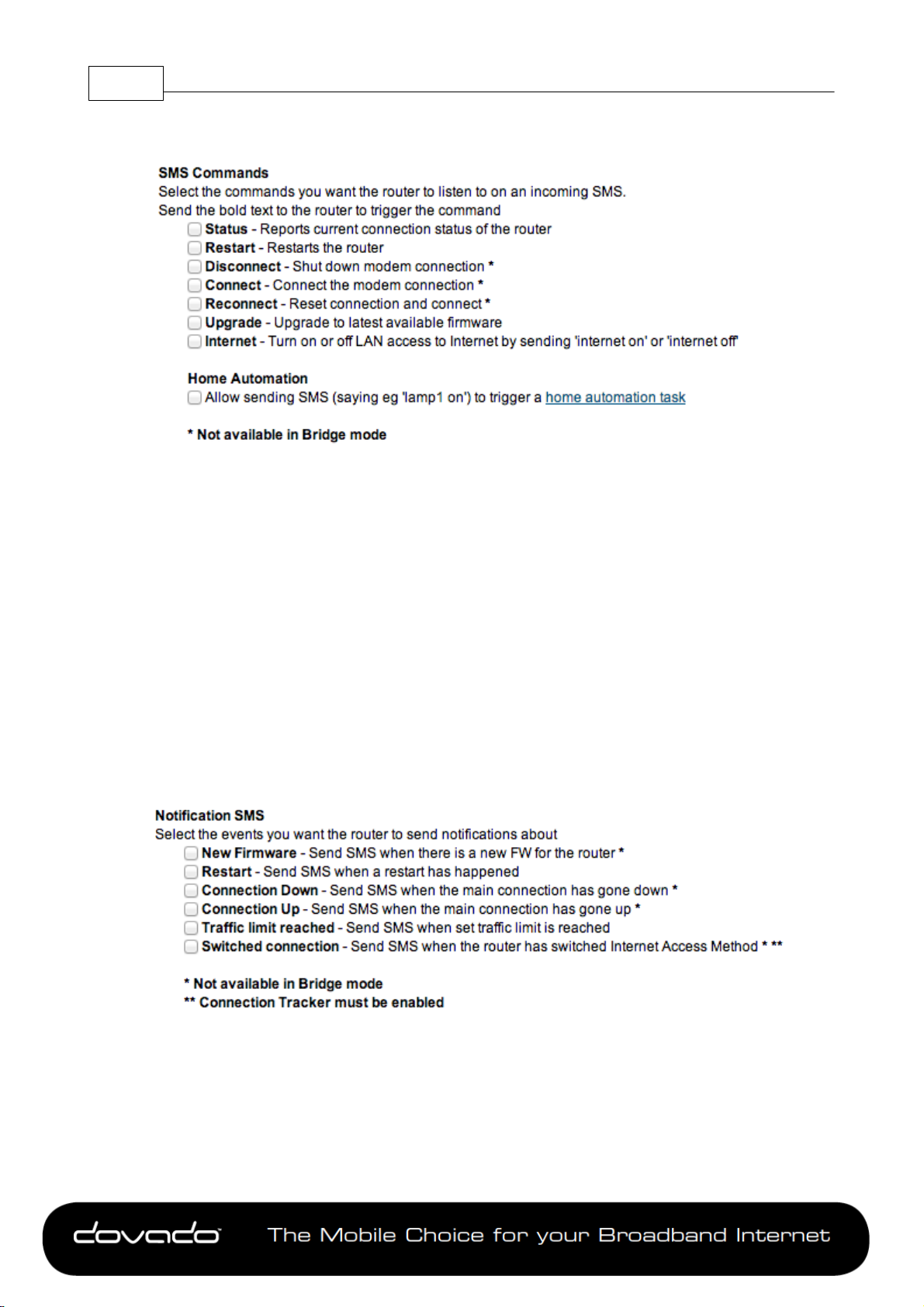
3.8.3.1 Remote Commands
The short text commands are: Status, Restart, Disconnect, Connect (or Reconnect), Upgrade.
Status: The router will reply to you stating that it's either connected or disconnected from the
Internet. It will also contain the IP address (if connected) of it's Ethernet WAN / USB Modem along
with signal information.
Restart: The router will restart itself.
Disconnect: The router will disconnect itself from the mobile broadband network. Internet
connection will be dropped, though SMS will still be active.
Connect (or Reconnect): The router will connect itself to the mobile broadband network. Internet
connection will be enabled.
Upgrade: You can instruct the router to fetch the latest firmware release directly from a Dovado
firmware server, without involving your use of a computer.
3.8.3.2 Notification SMS
Unexpected events which occur in regards to the Internet connection along with the overall status
of the router can be reported by SMS to all numbers listed for "Notification". Notification messages
can be sent to recipients for the following events:
New Firmware: The router will check the Dovado firmware servers once a day for a new firmware
release. As soon as it has identified a newer release, you will be sent an SMS notification from the
router.
The Mobile Choice for y our Broadb and Interne t
© 2014 Dovado FZ-LLC
Page 17

Restart: In case the router was forced to restart itself after 3 unsuccessful connection attempts
(based on the settings located in the Connection Tracker). A restart can also be affected by an
unexpected power failure.
Connection down: The Internet connection has been dropped. The router at this point has
acknowledged a drop, and is working on resolving this situation by either redialing the connection,
restarting itself or switching connection to the secondary Internet interface (depending on what has
been defined in the Internet–>Connection Tracker site)
Connection up: An Internet connection has been established. It is very likely that your router will
be handed a new IP address from the operator.The SMS will display the new IP address in case
you would like to remotely connect to it for administration purposes.
Traffic limit reached: More information about this is available in section Notification of Data Traffic
Usage.
Switched connection: In case your Connection Tracker has been configured to automatically
perform a connection fail-over between two interfaces, you will be notified of this change, along
with further information pertaining to that new connection.
3.8.4 Settings
Menu System 17
To activate the usage of any SMS features, click on Activate the SMS handler. By default, the
router will select the Auto method for retrieving the incoming messages. You can also manually
select which method it should access the messages, be it either from the SIM card or from the
USB modem. Auto mode will attempt both.
Should the router experience any issues in receiving text messages from your phone, then type in
the SMS Service Center number that is tied to the SIM card you are using inside the USB modem.
If you do not know what it is, then either check the advanced settings within the modem dashboard
software (when using modem in computer), or contact your mobile operator for details. Make sure
to insert the SMSC telephone number in international dialing format.
3.8.5 Phonebook
If you are sending frequent SMS texts to a regular list of recipients, then enter those recipients to
the router's Phonebook. Once inserted, you can compose a new message and simply select the
recipient by name.
All entries into the Phonebook are to be stored in the international number format. It is also
possible to store Short Numbers as well.
3.9 NAS
If you insert into a unused USB port an external USB hard drive or thumb drive, you can share out
the storage centrally throughout your entire private network.
For further information, visit http://www.dovado.com/NAS
3.9.1 Info
The router allows you to insert a USB Hard Drive, Thumb Drive or MicroSD card and act as a
centralized storage server for all the shared files within your network.
The NAS functionality supports storage drives that are formatted for NTFS and FAT32 file formats.
The NAS implementation provides two modes of access to these files SMB (Server Message
Block) and FTP (File Transfer Protocol).
The Mobile Choice for y our Broadb and Interne t
© 2014 Dovado FZ-LLC
Page 18

Reference Manual 7.1.518
3.9.2 Shares
In order to share out a storage drive, you must pair the drive together with a unique name. Enter
the name you wish to use, and select the drive from the drop-down menu. Make sure to also select
which sharing method you wish to use for that specific drive. The SMB method is a regular network
share, whereas FTP is a File Transfer Protocol service that requires you to use an FTP client on
your computer.
For NTFS formatted disks the 'ISO-8859-1'-encoding for file names will be used by default (shown
as NTFS/ISO in the user interface). If you want to use 'UTF-8' instead of 'ISO-8859-1', then check
the box labeled "Enable UTF-8 for filename encoding" when adding a new share. The new share
will show up as 'NTFS/UTF-8'. When creating multiple shares from the same disk, the encoding
must remain the same.
For further information, visit http://www.dovado.com/NAS
3.9.3 Users
This page allows you to manage your login account credentials, as well as add additional users
along with corresponding privileges. The usernames and passwords can be modified, and services
can be enabled/disabled.
For example, if you wish to allow users the possibility to use the SMS API, then add/modify an
account and select only the API SMS. Apply all changes by clicking on the Save Settings button,
and applying a restart of the router.
Apply all changes by clicking on the Save Settings button, and applying a restart of the router.
3.9.4 SMB
The most common network share which can be accessed by all operating systems (Windows,
MAC, Linux, etc). It allows you to map a network drive on your computer, and then drag-and-drop
files in/out of that network share. Typical transfer rates are between 6-9MB/s (50-75Mbps).
3.9.5 FTP
This optional method is quite practical for several reasons. It allows certain network devices (other
than your regular desktop/notebook computers) to dump/fetch files from the storage server in a
simplified manner. In many cases with Ethernet-based security cameras, the video/photo images
are typically uploaded to an FTP server.
Transfer rates tend to be somewhat higher with FTP than with the SMB protocol.
3.10 AUTOMATION
This menu covers Home Automation. You can take control of the lighting as well as power up other
appliances within your home from your computer or phone.You can also control what time Ethernet
LAN and WiFi clients should be able to access the Internet.
For further information, visit http://www.dovado.com/automation
3.10.1 Info
The router can be used as a server for Home Automation, allowing you to remotely control
automation receivers (containing integrated radio receivers) for powering on/off household
appliances, such as lamps.
You can also control what time Ethernet LAN and WiFi clients should be able to access the Internet
within the Scheduler sub-menu.
In order to get the Home Automation up and running, the following is required:
1. A TellStick from Telldus Technologies or a Gembird SilverShield/Energenie plugged into a
vacant USB port in the router.
2. If using TellStick, you'll require compatible home automation receivers.
3. Configuration of the router.
Begin by configuring Automation->Aliases for your devices. The uniquely named receivers
The Mobile Choice for y our Broadb and Interne t
© 2014 Dovado FZ-LLC
Page 19

(aliases) can then be controlled by:
1. Sending an SMS containing short commands such as "lamp1 on".
2. Using the DOVADO Remote Control app for iOS/Android.
3. Using the DovTelCon Windows desktop application for PC.
4. Setting up a schedule for triggering of events.
5. Manual control from the graphical web user interface (UI).
Visit the relevant pages on http://www.dovado.com for further information on this section.
The router can also be used to awaken a computer (that is on standby) if connected to one of the
LAN ports on the router by Ethernet cable. The computer itself has to support the Wake-On-LAN
(WOL) function.
To do so, you must add your computer as an Alias where you select the Protocol:"Wake on LAN"
and enter the MAC address of the computer's Ethernet LAN network card.
3.10.2 Aliases
To enter a home automation receiver into the router configuration, you must first name it in the
Alias Configuration page. To do this, name a receiver such as "Test1" (for example) and its
corresponding Protocol, along with House and Channel. This is typically adjustable on the receiver
device itself. Each entered alias must have a unique name, House and Channel. Upon entering
each individual alias, click on Add Alias.
Menu System 19
How to configure self-learning wall-plugs:
Go to Automation>Aliases.
Insert an Alias lamp1 (for example).
Select the corresponding protocol.
Select a Unique ID or hit Random ID (any will do) and Channel (any will do).
Click on Add Alias.
On the alias you wish to pair with your wireless receiver, push Learn after having pushed the self-
learning button on the wireless receiver you have plugged into the wall. This will then pair the two
units together.
3.10.3 Groups
If you wish to cluster several appliances into a group, you can tick in the various alias boxes and
label them as a group. This is particularly useful if you have several lamps in a specific room (such
as bedroom), or several appliances within the same category; such as lamps.
It is also possible to create groups of days (for instance weekdays vs. weekends) in order to
simplify clustering of events.
3.10.4 Scheduler
Allows you to schedule in events to power on/off individual/all devices around the home. Besides
applying general daily rules, it also allows you to create specific one-time events.
You can also control what time Ethernet LAN and WiFi clients should be able to access the
Internet. For example, specific rules can be created to allow Internet access between Monday to
Friday between 08:00 to 17:00, whereas all other times it will not be possible to access the the
Internet. The router will still be connected to the Internet, however your network devices will be
blocked from accessing the Internet.
3.10.5 Manual control
You can manually control the aliases throughout your home via the web interface in the router. To
do so, go to the Automation->Manual control page and select which device(s) you would like to
control. Select the state of operation you'd like each alias to be (ON or OFF) and push Execute.
The Mobile Choice for y our Broadb and Interne t
© 2014 Dovado FZ-LLC
Page 20

Reference Manual 7.1.520
3.11 POSITION
With help of your location coordinates, this router is capable of applying the information into use
with several applications, such as knowing what time the sun will rise and set each day when using
Home Automation.
3.11.1 Info
The router can be used as a tracking device by showing its positioning e.g. on a Google MapTM.
The router support 2 different types of position services:
1. USB-based GPS receiver: As new GPS devices are constantly introduced to the market, go to
http://www.dovado.com to see if your device is supported.
2. Fixed position: Allows you to manually enter your current position in the Web interface.
For detailed information, go to Position->Info and for enabling the function go to Position-
>Settings to select the positioning method you want to use.
3.11.2 Map
The map will present the location of your router, based on the coordinates that were either
manually applied or automatically gathered from a GPS USB dongle.
3.11.3 GPS Settings
In order for certain Home Automation features to work (Sunrise/Sunset), the router needs to know
its geographic whereabouts. There are two methods available within this menu. First option is to
use a GPS USB dongle in one of the vacant USB ports on your DOVADO router. The GPS dongle
will then periodically update the location if (for instance) in a moving vehicle. The second option is
simple as it is intended for fixed environments such as a home or office. All you are required to do
is to insert the Latitude and Longitude of the router's location. For further information, visit http://
www.dovado.com/gps
Custom API key: It is possible to enter your own Google Maps key , For further info visit https://
developers.google.com/maps/documentation/javascript/tutorial
3.12 SYSTEM
The System sub-menu offers you to alter some of the advanced settings within the router, along
with the user management.
3.12.1 Users
This page allows you to manage your login account credentials, as well as add additional users
along with corresponding privileges. The usernames and passwords can be modified, and services
can be enabled/disabled.
For example, if you wish to allow users the possibility to use the SMS API, then add/modify an
account and select only the API SMS. Apply all changes by clicking on the Save Settings button,
and applying a restart of the router.
Apply all changes by clicking on the Save Settings button, and applying a restart of the router.
3.12.2 Remote Management
The settings for enabling remote management of the router from another location.
Web Access Port: Select which port you would like to access the router interface page from the
Internet. The Standard port is port 80, which is the regular port for HTTP.
Example: Should you wish to access the settings on your router from elsewhere on the Internet,
simply open a browser, type in http://<ip address of router>:<port>.
For instance, http://183.168.0.35:4430.
The Mobile Choice for y our Broadb and Interne t
© 2014 Dovado FZ-LLC
Page 21

Menu System 21
Status Bar: It possible to hide the status bar from being showed when connecting to the router
from remote location
Hostname lookup interval: Select how often a hostname entered in the Client Access List should
be updated. Frequent updates are needed if the IP-address behind the hostname changes often.
Allowed Clients: The router will only allow access for clients visible in the Client Access List. To
put a client in the list, enter the corresponding IP-address or Hostname (For instance 217.65.34.12
or myhost.dyndns.org) in the Host/IP-field and click Add to list. Repeat the procedure in order to
grant more clients access. Access can be granted from anywhere on the Internet by marking "Any
Host" and pressing "Add to List".
Here you can give permission on which interfaces it is allowed to access the router. It is possible to
access the router on both the Direct and the PPTP interface
Show Mapping: Displays the router's view of IP-addresses associated with hostnames in the
"Client Access List".
All changes will take effect upon restart of the router
GPS API The router uses a software called gpsd (version 2.39) which has a API on TCP port
2947. For more info about the gpsd API please visit http://catb.org/gpsd/
3.12.3 Network Settings
Here you can alter the MTU, MRU and ICMP for the Internet connection.
Network Settings
To alter the MTU & MRU values, disable the option "Let the router select safe settings" and
manually enter the MTU & MRU values. It might also be important to enable the MSS Clamping
once having altered the values. The router also contains certain templates that are operator
specific in cases where deviations are known.
ICMP Settings
If enabling "Drop Ping requests" the router will not respond to incoming ICMP packets such as ping
request.
3.12.4 NTP
Dovado routers synchronize their clocks via NTP (Network Time Protocol) servers located out on
the Internet. The synchronization occurs upon each new connection with the Internet, be it the initial
(when powering up) or even during a redial while the router is on.
For the router to contain the accurate time zone, you may have to manually select your region/
country/city to make sure the router will be able to present you with the right time and date. By
making this selection, your router will automatically update itself whenever a time change occurs
throughout a year, depending on the time zone you’re in.
By default, the router will attempt to auto-detect the time zone when using a USB mobile broadband
modem as your primary form of Internet access. Should this fail, then select your location manually.
If you wish to use your own NTP server settings, then activate the Custom NTP option, and fill in up
to two different IP/DNS addresses of such servers.
3.12.5 E-Mail
The E-Mail sender will dispatch notifications of your consumed Internet data traffic. Enter the EMail address destination along with the SMTP server you wish to use in order to send out the EMails. To enable/select the Internet traffic reports, visit the Internet->Traffic page and select the
notification method for the chosen quota.
If you are unsure of which SMTP server settings your mail service uses, then kindly check with your
The Mobile Choice for y our Broadb and Interne t
© 2014 Dovado FZ-LLC
Page 22

Reference Manual 7.1.522
e-mail service provider. Aside from inserting the correct username and password, it is important to
confirm which SMTP port and authentication protocol you should use. After saving these settings,
click on Send Test Message to verify.
3.12.6 Log
The log shows what the router has done since powering/booting up. It may provide you a good
insight into any problems you may be facing with your mobile broadband connection. The clock
(timestamp at the beginning of each line) makes its first synchronization once the router has
connected itself to the Internet. The log file is not stored between restarts.
3.13 UPGRADE
The latest firmware is available on http://www.dovado.com/firmware
Warning! Do not remove the power or the USB modem during upgrading as this will break your
router!
3.13.1 Firmware Utility Upgrader
The simplest recommended method of firmware upgrade is to visit http://www.dovado.com/
firmware and download the latest version of Firmware Utility Upgrader. The Upgrader allows you to
quickly establish contact with the router, type in the router's password, and perform the upgrade
with the click of a button.
3.13.2 HTTP Method
Point a web browser to http://www.dovado.com/firmware and download the upgrade file to your
computer. Remember where you store the file. Go to Upgrade->Upgrade HTTP. Click on the
Browse button and select the upgrade file you just downloaded, and then click on Open. Click on
Start HTTP Upload to start the upgrade process.
When the upgrade is done, the router will automatically restart and a login button will appear in the
web browser. The router is ready to use once it has been restarted.
3.13.3 Live Upgrade
Live upgrade will keep your router updated with the latest firmware release available on Dovado‘s
servers. It automatically checks for new firmware once a day, however it is also possible to check
manually by click on the Check Firmware .
3.13.4 FTP Method
If you have an FTP server you have the choice to upgrade the router via FTP.
Once the upgrade file is on the FTP server in the root directory. Go to Upgrade->Upgrade FTP.
Then, type in the IP address of the FTP server under FTP Server IP and the filename under
Filename, then click on Start FTP Download to start the upgrade process.The text "Restarting..."
will appear in your web browser when the upgrade has finished.
Note: In order to use the FTP upgrade option, the FTP server which contains the firmware image
must be accessible via an anonymous FTP account.
Close the web browser and wait until the router has restarted. The router is now ready to use.
3.13.5 Configurations
This function allows you to create, as well as restore, the working configuration of your Dovado
router. Each backup you save to your computer will contain all the configuration parameters you
have entered in your router.
Should you have performed a factory reset to clear out all your settings, you can then restore your
settings by uploading your saved configuration file via this interface.
To save the current configuration of your router to your computer, go to Upgrade->Configurations,
then simply push the Download button. To restore your configuration, click on Browse (to locate the
file on your computer), and then push Upload.
The Mobile Choice for y our Broadb and Interne t
© 2014 Dovado FZ-LLC
Page 23

Tip: The configuration file which you download from your Dovado router can also be used on other
routers of the same model and firmware revision. This can come in handy if performing a massdeployment of clone configurations.
3.14 RESTART
Push Restart in order to restart the router and initiate all the settings you have saved within the
menu.
3.15 LOGOUT
Normally, the login session will expire after 10 minutes of no activity. Should you wish to manually
terminate the login session, then click on Logout
Menu System 23
The Mobile Choice for y our Broadb and Interne t
© 2014 Dovado FZ-LLC
Page 24

Reference Manual 7.1.524
4 API
The Application Programmable Interface (API) allows you to create your own custom interface with
the router. You can control certain features such as Home Automation, as well as manage SMS
messaging.
4.1 Enabling the API
To enable the API please do the following.
LAN Access:
Go to System-> Remote Management
Click Enable LAN management
Click API Over LAN
Click GPS Over LAN
WAN Access:
Go to System-> Remote Management
Click Enable WAN management
Enter the IP address or hostname of the trusted client or check 'all' to enable WAN access for any
client. Tick in the API, HOME and SMS -boxes for Home Automation and SMS access for the
client.
Do not forget to reboot the router after activating the API.
4.2 Connecting to the API
The API operates on port 6435.
To connect you can for example, type in the following within a console:
telnet 192.168.0.1 6435 (or change 192.168.0.1 to the IP of your router).
If the connection was successful you will receive something similar to:
This is version X.Y of the API
SMS is enabled and HOMEAUTOMATION is enabled for you
Followed by a '>>'-prompt
4.3 Logging in to the API
The API uses the Username and Password as specified in the Web GUI.
To log in as user admin, type:
user admin
When prompted for a password, enter it using the following syntax:
pass password
(The user and password is configured on the SYSTEM->USERS page)
If the login fails, verify & re-enter your credentials until access is granted.
4.4 API Syntax
To display information about the GUI functions and syntax, type help.
Commands:
help (show this help)
exit|quit|bye (close the telnet session)
user [username] (log in as user)
The Mobile Choice for y our Broadb and Interne t
© 2014 Dovado FZ-LLC
Page 25

pass [secret_password] (log in with secret_password)
info (prints general information about the router)
services (lists services)
upgrade (upgrades router to latest available firmware)
API 25
Tellstick:
ts aliases (lists configured aliases)
ts groups (lists configured groups)
ts turn [alias] [on]/[off]
ts dim [alias] [0...100] (Dimming the device to XX%)
ts dims [alias] [0...100] (Turns the device off before dimming to XX%)
ts dimot [alias] [Start level 0...100] [Stop level 0...100] [Duration xx min]
ts add [alias] [protocol] [house] [channel]
ts add_group [alias] [list_of_device_aliases] (the list is a space separated list of devices)
ts remove [alias]
ts remove_group [alias]
examples: ts add MYLAMP WAVEMAN A 3
ts remove MYLAMP
SMS:
sms list (returns number of unread/read messages)
sms send [PDU]
sms sendtxt NUMBER [ENCODING]
sms recv [ID] (returns PDU with ID or all PDUs in the inbox if ID is empty [ID:PDU])
sms recvtxt [ID] (returns cleartext SMS with ID or all cleartext SMS in the inbox
sms del ID
4.5 Router info
To display information about the router, execute the command:
info
(Dim from start to stop level over XX minutes)
ts turn MYLAMP on
NUMBER:international format without the leading +. A leading s indicates short SMS
(eg s4612345678)
ENCODING:ISO|UCS (ISO for ascii < 256). Leave blank for autodetection
if ID is empty)
It will respond with a list of parameters, for example:
Firmware_Revision:7.0.0
New firmware available:yes
API_version:1.4
PRODUCT_NAME=Dovado PRO
SIGNAL_STRENGTH=TRAFFIC_MODEM_TX=0
TRAFFIC_MODEM_RX=0
TRAFFIC_WAN_TX=0
TRAFFIC_WAN_RX=0
CONNECTION=modem
MODEM_STATUS=DISCONNECTED
EXTERNAL_IP=DATE=2010-04-10
TIME=08:11
GPS_TYPE=FIXED
GPS_LAT=59.2222
GPS_LONG=18.1111
SUNRISE=05:48
SUNSET=19:50
SMS_UNREAD=0
SMS_TOTAL=0
CONNECTED_DEVICES=TELLSTICK
4.6 Upgrade via API
The command info will show if there is a new firmware available
Firmware_Revision:7.0.0
New firmware available:yes
API_version:1.4
To start a firmware upgrade of the router, execute the command:
upgrade
The Mobile Choice for y our Broadb and Interne t
© 2014 Dovado FZ-LLC
Page 26

Reference Manual 7.1.526
4.7 SMS
The router can handle both SMS´s in cleartext (UTF-8/UCS encoded) and in PDU mode.
To view the clear-text contents of a PDU you need to convert it either on your own or, preferably,
using a third-party software such as SMS Server Tools 3
Below is the API commands available related to SMS
SMS:
sms list (returns number of unread/read messages)
sms send [PDU]
sms sendtxt NUMBER [ENCODING]
sms recv [ID] (returns PDU with ID or all PDUs in the inbox if ID is empty [ID:PDU])
sms recvtxt [ID] (returns cleartext SMS with ID or all cleartext SMS in the inbox if ID is empty)
sms del ID
4.7.1 Listing the number of SMS/PDUs
sms list (returns number of unread/read messages)
You can list the number of SMS/PDUs on your router using: sms list
The first digit of the response shows the current number of unread SMS / PDU’s and the second
digit the total amount in the inbox.
NUMBER:international format without the leading +. A leading s indicates short SMS (eg s4612)
ENCODING:ISO|UCS (ISO for ascii < 256). Leave blank for autodetection
4.7.2 Sending SMS
The API can handle two ways of send SMS, either by receiving a PDU or via UTF-8/UCS encoded
text messages.
4.7.2.1 Sending an SMS via text
sms sendtxt NUMBER [ENCODING]
NUMBER:international format without the leading +. A leading s indicates short SMS (eg s4612)
ENCODING:ISO|UCS (ISO for ascii < 256). Leave blank for autodetection
To send a SMS via text use the command sms sendtxt
Example:
>>sms sendtxt 46791044794 ISO
This is a text message
.
>>
4.7.2.2 Sending an SMS via PDU
sms send [PDU]
To send a SMS, you first have to make a PDU of it. Once you have the PDU, use the following
syntax: sms send <pdu>
Example:
sms send 07910447946400F011000A9270042079330000AA0CC337392C2F83A6CD292804
4.7.3 Reading an SMS
The API can handle two ways of reading SMS, either by showing a PDU or via UTF-8/UCS
encoded text messages.
The Mobile Choice for y our Broadb and Interne t
© 2014 Dovado FZ-LLC
Page 27

4.7.3.1 Reading an SMS via text
sms recvtxt [ID] (returns cleartext SMS with ID or all cleartext SMS in the inbox if ID is empty)
To read a SMS via text use the command sms recvtxt
Example:
>> sms list
new/total
1/1
Stored IDs: 1
>> sms recvtxt 1
From: 46XXXXXXXXX
Sent: 12-07-23 11:27:36
Alphabet: UTF-8
ID: 1
Räksmörgås
End of SMS
API 27
>>
4.7.3.2 Reading an SMS via PDU
sms recv [ID] (returns PDU with ID or all PDUs in the inbox if ID is empty [ID:PDU])
You can list all the current PDUs in your in the inbox using: sms recv
This will list all PDUs using in the format ID:PDU where ID is a unique internal descriptor of that
PDU (used for removing PDUs).
Conversion is needed to see the actual contents of the PDU.
Example:
>> sms list
new/total
1/1
Stored IDs: 1
>> sms recv 1
1:07916407970900F1040B91640XXXXXXXF40000217032117263800A
>>
4.7.4 Removing an SMS/PDU
sms del ID
First you need the ID of the PDU you want to remove. It can be obtained using the sms recv
command. Then to remove a SMS/PDU, type: sms del ID
Example:
>> sms list
new/total
0/1
Stored IDs: 1
>> sms del 1
The Mobile Choice for y our Broadb and Interne t
© 2014 Dovado FZ-LLC
Page 28

Reference Manual 7.1.528
>>
4.8 Check services available
Services available in current session:
To display which services that are available in current session, execute the command:
services
It will respond with the services (Home Automation and SMS) that are currently available
Example:
HOMEAUTOMATION=enabled
SMS=enabled
4.9 API Coding
The API can easily be extended with a custom front-end. When implementing a front-end, mind the
following:
The router might be behind a high-latency connection. Set a high timeout for your connection.
When logging in to the API, the password must be encoded either ISO-8859-1or UTF-8
When executing a command (for example ts aliases), each line of output from the API is
terminated with LF (Line Feed, ASCII character 10d) and the last line of output from the
command is ETB (End of Transmission Block, ASCII character 23d).
Since there can only be one instance of the API running on the Router, a session that has been
inactive for more than 60 seconds will be dropped in favor of a new session.
4.9.1 Example code
API example code for different platforms are available on http://www.dovado.mobi/
4.9.1.1 PHP
Below is a sample php script that will connect to the router and then send a SMS via the API
<?php
error_reporting(E_ALL);
echo "Code example on how to send a SMS via the Dovado router API\n";
/* The following variables are set
$username= your username to the router with API access
$password= your password for the above username
$ipaddress = ipaddress of your router
$api_port = 6435;
$smsnr = Number to send SMS to
$smstxt = Message content for your SMS
*/
$username = "admin";
$password = "password";
$api_port = 6435;
$ipaddress = ('192.168.0.1');
$smsnr = "Enter your phonenumber in international format (4670000000)";
$smstxt = "Enter Text Here";
$readbuf = '';
/* Function to wait for >> answers */
function respons_wait($insocket)
{
do {
$readbuf = socket_read($insocket, 4096, PHP_BINARY_READ) ;
}while (strpos($readbuf,'>>') === false);
$readbuf = '';
}
/* Create a TCP/IP socket. */
$socket = socket_create(AF_INET, SOCK_STREAM, SOL_TCP);
The Mobile Choice for y our Broadb and Interne t
© 2014 Dovado FZ-LLC
Page 29

API 29
if ($socket === false) {
echo "socket_create() failed: reason: " . socket_strerror(socket_last_error()) . "\n";
} else {
echo "OK.\n";
}
echo "Attempting to connect to '$ipaddress' on port '$api_port'...";
$result = socket_connect($socket, $ipaddress, $api_port);
if ($result === false) {
echo "socket_connect() failed.\nReason: ($result) " . socket_strerror(socket_last_error($socket)) . "\n";
} else {
echo "\nConnected to router\n";
}
respons_wait($socket);
/* Sending username to the API */
echo "Sending User Name...\n";
socket_write($socket, "user $username \r\n", strlen($username)+8);
echo "OK.\n";
respons_wait($socket);
/* Sending password to the API */
echo "Sending password...\n";
socket_write($socket, "pass $password \r\n", strlen($password)+8);
echo "OK.\n";
respons_wait($socket);
/* Setting up destination SMS number */
echo "Sending SMS number...\n";
socket_write($socket, "sms sendtxt $smsnr \r\n", strlen($smsnr)+15);
/* Sending text */
socket_write($socket, "$smstxt \r\n", strlen($smstxt)+3);
/* Sending end of message */
socket_write($socket, ".\r\n",3);
respons_wait($socket);
echo "Closing socket...";
socket_write($socket, "bye \r\n",6);
socket_close($socket);
echo "OK.\n\n";
?>
5 Troubleshooting
Dovado routers are designed with simplicity in mind. If you are experiencing difficulties with certain
features or unable to get online via the router, then kindly check the hints on the Troubleshooting
page within the router menu. If those hints do not help, then proceed to http://www.dovado.com/
support for further details. If you still cannot find the answer, then take contact with us via http://
www.dovado.com/support/support-form
5.1 Scenarios
The following scenarios should assist you in enabling your router for Internet access, depending on
which type of USB modem you have inserted into the router.
If your scenario is not available in this guide, then please visit http://www.dovado.com/support for
latest update. Once the information has been inserted, the unit will automatically try to establish a
connection to the operator's network. A solid green light on the Internet LED indicates a successful
connection.
Note: Mobile operators typically have an Access Point Name (APN) as the key relevant point of
entry towards the mobile broadband network. Make sure to have the name of your APN in advance
of configuring your USB modem. If you are using any other technology besides 2G/3G or 4G, you
might not require an APN.
The Mobile Choice for y our Broadb and Interne t
© 2014 Dovado FZ-LLC
Page 30

Reference Manual 7.1.530
5.1.1 Scenario 1: USB modem using a SIM card
Go to Modem->Modem Settings page.
Select your country, and operator Access Point Name.
If your operator or APN isn’t available, then insert it manually into the blank field.
Enter PIN code of your SIM card if necessary.
If your mobile broadband SIM card requires further username & password authentication towards
the mobile network, then click on “My subscription requires username and password”, and enter
those specific details accordingly.
Save Settings.
Restart the router
5.1.2 Scenario 3: Fixed connection through the WAN port
In the Internet->Internet Connection page, choose Ethernet cable in WAN port as the primary
Internet connection .
Push Save Settings.
Restart the router
5.2 Frequently Asked Questions
Read further to see if any of the following scenarios will assist you in getting online with the
Internet.
For updated Frequently Asked Questions (FAQ), please visit http://www.dovado.com/faq
5.2.1 My router is not connecting to the Internet!
Do all of the following:
First check if the Internet LED on the router is OFF. If so, continue with the following steps
otherwise go to section The router indicates Internet connectivity, yet I can't surf!.
Please verify that you are able to connect to your mobile operator using the USB modem in your
computer!
Always insert the USB modem into the router before powering it on!
Log into the router on default address http://192.168.0.1/
Check that your router has identified the USB modem. If not, check if your USB modem is
supported:
http://www.dovado.com/modems
Check the signal strength in the Modem->Modem Status page.
Verify that a correct Access Point Name (APN) and/or Username and Password has been
inserted in the MODEM->MODEM SETTINGS page
Check that the APN information provided by your mobile operator is identical with the APN
information used in the router settings.
If using a PIN code on your SIM card, insert it in Modem->Modem Settings page
5.2.2 The router indicates Internet connectivity, yet I can't surf!
Test to see if you can do the following (in listed order):
1. Ping the internal IP address of the router.
Ping the router on address 192.168.0.1 (see instructions for Window and Mac OS X below) and
see if pings are replied positively
If positive, then try the next step.
If negative, please try with another computer if possible. Also check your IP settings and switch
to DHCP (dynamic IP) settings on your computer's network interface.
2. Ping an external IP address.
Try to ping www.yahoo.com and note if 4 pings are replied positively.
If so, then please check your web browser's settings for any conflicting proxy settings.
Windows
The Mobile Choice for y our Broadb and Interne t
© 2014 Dovado FZ-LLC
Page 31

Troubleshooting 31
1. Click on Start followed by Run and type in cmd.
2. Once the black command prompt is open, type in ping 192.168.0.1 followed by Enter.
Mac OS X
1. Click on Finder in the dock.
2. Then click on Utilities in the Go menu.
3. Make then sure to double-click on Network Utility. In the Network Utility window, click on the Ping
tab. Enter the IP address 192.168.0.1 in the provided field. Click on Ping.
5.2.3 I forgot my router's password or username for accessing the router interface
The default username and password for logging in to the router interface is "admin" and
"password", if you have changed it - tough luck! Nothing to do now but apply a factory reset, which
will wipe out all your settings. To do this, make sure your router is running and fully booted. Then
hold down the RESET button on the front of the router for about 7-10 seconds until the PWR
(power) lamp begins to flicker on the front of the router. At this point, you can release the RESET
button and wait approximately 2 minutes before logging in again. Make sure to write down your
password next time.
It is also advised that, once you have made your ideal configuration, you save it to your computer in
case of future manual resets of the router. To do this, go to Upgrade->Configurations page and
extract a backup configuration file.
5.2.4 My firmware upgrade seems to have failed and I cannot access my router anymore
Download the latest version of the DOVADO Firmware Utility Upgrader for your router, and select
the Rescue tab to restore your router.
http://www.dovado.com/firmware
5.2.5 My computer claims to be connected to my DOVADO network, but I can't reach/log onto the configuration page
The configuration page is reached through the routers IP address, which by default is 192.168.0.1.
If this page returns an error start by doing a factory reset on the router by holding the reset button
for about 8 seconds and then wait for 2 minutes. If that doesn't do it, clear the cache in your web
browser. Also try disabling any antivirus, firewall or other security software as these can interfere
with accessing the interface.
5.2.6 I changed the settings for the WLAN and now some or all of my computers or devices can't access it anymore
Most computers and devices remembers the settings for a WLAN by default, so that you don't have
to enter the passkey every time you connect to it. This is usually convenient but if you change the
passkey or remove the encryption altogether, the device will still try to connect with the old passkey.
You can change this manually but it is usually easier and faster just to "forget" the network and then
reconnect.
Instructions for doing this in Windows and Mac OS X are as follows.
Windows 7
1. Go to Control Panel -> Network and Internet -> Network and Sharing Center -> Manage
wireless networks.
2. Right click your WLAN in the list and choose Remove network.
3. Reconnect to the WLAN.
Windows XP
The Mobile Choice for y our Broadb and Interne t
© 2014 Dovado FZ-LLC
Page 32

Reference Manual 7.1.532
1. Go to Control Panel -> Network Connections and right click Wireless network connection and
choose Properties.
2. Go to the Wireless Networks tab and select your WLAN under Preferred networks and click
Remove.
3. Reconnect to the WLAN.
Mac OS X
1. Go to System Preferences -> Network -> Airport -> Advanced
2. Select your WLAN in the list and click the minus sign to remove it.
3. Reconnect to the WLAN.
5.2.7 How do I connect my game console (XBOX, PS3, etc) to the Internet?
You may need to open ports for the online games to work, often just enabling UPnP which opens
ports automatically does the trick (LAN->UPnP).
If not, you will have to find out which ports and protocols are required and then see the Port
Forwarding page for instructions on how to set it up manually.
5.2.8 I have enabled the SMS functionality, but I still can't send/receive SMS
First make sure that the SMS functionality is supported by both the USB modem on our list, and
that the SIM card is activated by your operator for SMS traffic. The simplest way to know is to try
the USB modem directly in the computer, and see if messages can be sent/received.
Following that, check the USB modem's connection manager in your computer to see which SMS
Service Center (also known as SMS-C) it is using.
Having identified the SMS-C, place that number into the SMS Service Center field in your router,
located under SMS -> Settings. If this does not help, try upgrading the firmware on your USB
modem.
An upgrade of the USB modem firmware might also solve the issue.
5.2.9 My connection speed isn't as good with the router as when I use the modem in my computer
Check that you are using the EXACT same APN in the router as you are in the dialer software in
the computer.
Check that you are using the USB modem in the exact same angle and position when conducting
speeds tests with/without the router involved.
If you're using a 4G modem, make sure you separate the router and modem at least 55 cm with
USB cable to avoid interference between WLAN and 4G.
For more information on this issue: http://www.dovado.com/4G
Verify with a network cable to a LAN port on the router in case you are using WLAN.
Disconnect all other computers as they might be downloading updates in the background.
Make sure the Dovado router aswell as the USB modem have the latest stable firmware.
Go to System->Network Settings and deselect Let the router select safe settings. Select the
appropriate preset from the drop-down menu. Save settings and then restart the router.
The Mobile Choice for y our Broadb and Interne t
© 2014 Dovado FZ-LLC
Page 33

6 Support
Should you require any technical support, please visit http://www.dovado.com/support
For Frequently Asked Questions (FAQ), please visit http://www.dovado.com/faq
If you are unable to find what you are looking for, please contact our support via http://
www.dovado.com/contactsupport
Troubleshooting 33
7
Open Source Notice
Open source software notice This product includes certain open source or other software
originated from third parties that are subject to the GNU General Public License (GPL), GNU
General Public License version 2 (GPLv2), GNU Library/Lesser General Public License (LGPL) ,
and different and/or additional copyright licenses, disclaimers and notices.
This program is distributed in the hope that it will be useful, but WITHOUT ANY WARRANTY;
without even the implied warranty of MERCHANTABILITY or FITNESS FOR A PARTICULAR
PURPOSE. See the GNU General Public License for more details.
3rd parties may obtain a complete corresponding machine-readable copy of the source code of
such software under the GPL, GPLv2 or LGPL at http://www.dovado.com/
Alternatively;
Dovado offers to provide such source code to you on CD-ROM for a charge covering the cost of
performing such distribution, such as the cost of media, shipping and handling, upon written
request to:
Dovado FZ-LLC
Dubai Internet City
Al-Thuraya Tower 1, office 504
P.O. Box 500422
Dubai, United Arab Emirates
This offer is valid for a period of three (3) years from the date of the distribution of this product by
Dovado.
7.1 GPL v2 Applications
Linux: Copyright by their respective authors.
Version: 2.6.36
License: GPL Version 2 License
Auth: Copyright (C) 2002 Bryan D. Payne & Nick L. Petroni Jr.
Version:
License: GPL Version 2 License
Bridge-utils: Copyright (C) 2000 Lennert Buytenhek
Version: 1.1
License: GPL Version 2 License
Busybox: Copyright by their respective authors.
Version 1.20.2
License: GPL Version 2 License
dnsmasq: Copyright (c) 2000-2011 Simon Kelley
Version: 2.59
License: GPL Version 2 License
The Mobile Choice for y our Broadb and Interne t
© 2014 Dovado FZ-LLC
Page 34

Reference Manual 7.1.534
ebtables: Copyright (C) 1999 Paul `Rusty' Russell & Michael J. Neuling
Version: 2.0.9
License: GPL Version 2 License
inadyn: Copyright (C) 2003-2004 Narcis Ilisei
Version: 1.99
License: GPL Version 2 License
iptables: Copyright (c) 2000-2001 Netfilter Core Team
Version: 1.4.10
License: GPL Version 2 License
ethtool: Copyright by their respective authors.
Version: 6
License: GPL Version 2 License
ntpclient: Copyright 1997, 1999, 2000, 2003 Larry Doolittle
Version:
License: GPL Version 2 License
polar_smtphelper: Copyright (C) 2006-2010, Brainspark B.V.
Version:
License: GPL Version 2 License
polarssl: Copyright (C) 2006-2010, Brainspark B.V.
Version: 0.14.0
License: GPL Version 2 License
smstools: Copyright (C) 2006- Keijo Kasvi
Version: 3.1.14
License: GPL Version 2 License
udhcpd: Copyright (C) 1999 Matthew Ramsay <matthewr@moreton.com.au>
Version: 0.9.9-pre
License: GPL Version 2 License
usb_modeswitch
Version: 0.9.7
License: GPL Version 2 License
wireless_tools: Copyright (c) 1997-2002 Jean Tourrilhes <jt@hpl.hp.com>
Version: 29
License: GPL Version 2 License
802.1x: Copyright (c) 2002-2003, Jouni Malinen <jkmaline@cc.hut.fi>
Version: 2.6.0.0
License: GPL Version 2 License
sispmctl: (C) 2004-2011 by Mondrian Nuessle, (C) 2005, 2006 by Andreas Neuper, (C) 2010 by Olivier Matheret for the
plannification part"
Version: 3.1
License: GPL Version 2 License
sunrise: Copyright (GPL) 2004 Mike Chirico mchirico@comcast.net
Version: 0.1.1
License: GPL License
smstools: Copyright (C) 2006- Keijo Kasvi
Version: 3.1.14
License: GPL Version 2 License
linux-igd:
Version:
License: GPL Version 2 License
ntfs-3g: Copyright (c) 2005-2007 Yura Pakhuchiy, Copyright (c) 2005 Yuval Fledel, Copyright (c) 2006-2009 Szabolcs
Szakacsits, Copyright (c) 2007-2009 Jean-Pierre Andre, Copyright (c) 2009 Erik Larsson
Version: 1.2412
License: GPL Version 2 License
samba: Copyright by their respective authors.
Version: 3.0.24
License: GPL Version 2 License
The Mobile Choice for y our Broadb and Interne t
© 2014 Dovado FZ-LLC
Page 35

stupid-ftpd:
Version: 1.0beta, 2001/03/23
License: GPL Version 2 License
7.1.1 GPL v2 License
GNU GENERAL PUBLIC LICENSE
Version 2, June 1991
Copyright (C) 1989, 1991 Free Software Foundation, Inc.
51 Franklin Street, Fifth Floor, Boston, MA 02110-1301, USA
Everyone is permitted to copy and distribute verbatim copies of this license document, but changing it is not allowed.
Preamble
The licenses for most software are designed to take away your freedom to share and change it. By contrast, the GNU
General Public License is intended to guarantee your freedom to share and change free software--to make sure the
software is free for all its users. This General Public License applies to most of the Free Software Foundation's software
and to any other program whose authors commit to using it. (Some other Free Software Foundation software is covered by
the GNU Lesser General Public License instead.) You can apply it to your programs, too.
When we speak of free software, we are referring to freedom, not price. Our General Public Licenses are designed to
make sure that you have the freedom to distribute copies of free software (and charge for this service if you wish), that you
receive source code or can get it if you want it, that you can change the software or use pieces of it in new free programs;
and that you know you can do these things.
To protect your rights, we need to make restrictions that forbid anyone to deny you these rights or to ask you to surrender
the rights. These restrictions translate to certain responsibilities for you if you distribute copies of the software, or if you
modify it.
Open Source Notice 35
For example, if you distribute copies of such a program, whether gratis or for a fee, you must give the recipients all the
rights that you have. You must make sure that they, too, receive or can get the source code. And you must show them
these terms so they know their rights.
We protect your rights with two steps: (1) copyright the software, and (2) offer you this license which gives you legal
permission to copy, distribute and/or modify the software.
Also, for each author's protection and ours, we want to make certain that everyone understands that there is no warranty
for this free software. If the software is modified by someone else and passed on, we want its recipients to know that what
they have is not the original, so that any problems introduced by others will not reflect on the original authors' reputations.
Finally, any free program is threatened constantly by software patents. We wish to avoid the danger that redistributors of a
free program will individually obtain patent licenses, in effect making the program proprietary. To prevent this, we have
made it clear that any patent must be licensed for everyone's free use or not licensed at all.
The precise terms and conditions for copying, distribution and modification follow.
TERMS AND CONDITIONS FOR COPYING, DISTRIBUTION AND MODIFICATION
0. This License applies to any program or other work which contains a notice placed by the copyright holder saying it may
be distributed under the terms of this General Public License. The "Program", below, refers to any such program or work,
and a "work based on the Program" means either the Program or any derivative work under copyright law: that is to say, a
work containing the Program or a portion of it, either verbatim or with modifications and/or translated into another
language. (Hereinafter, translation is included without limitation in the term "modification".) Each licensee is addressed as
"you".
Activities other than copying, distribution and modification are not covered by this License; they are outside its scope. The
act of running the Program is not restricted, and the output from the Program is covered only if its contents constitute a
work based on the Program (independent of having been made by running the Program). Whether that is true depends on
what the Program does.
1. You may copy and distribute verbatim copies of the Program's source code as you receive it, in any medium, provided
that you conspicuously and appropriately publish on each copy an appropriate copyright notice and disclaimer of warranty;
keep intact all the notices that refer to this License and to the absence of any warranty; and give any other recipients of the
Program a copy of this License along with the Program.
You may charge a fee for the physical act of transferring a copy, and you may at your option offer warranty protection in
exchange for a fee.
2. You may modify your copy or copies of the Program or any portion of it, thus forming a work based on the Program, and
copy and distribute such modifications or work under the terms of Section 1 above, provided that you also meet all of these
conditions:
a) You must cause the modified files to carry prominent notices stating that you changed the files and the date of any
change.
The Mobile Choice for y our Broadb and Interne t
© 2014 Dovado FZ-LLC
Page 36

Reference Manual 7.1.536
b) You must cause any work that you distribute or publish, that in whole or in part contains or is derived from the Program
or any part thereof, to be licensed as a whole at no charge to all third parties under the terms of this License.
c) If the modified program normally reads commands interactively when run, you must cause it, when started running for
such interactive use in the most ordinary way, to print or display an announcement including an appropriate copyright
notice and a notice that there is no warranty (or else, saying that you provide a warranty) and that users may redistribute
the program under these conditions, and telling the user how to view a copy of this License. (Exception: if the Program
itself is interactive but does not normally print such an announcement, your work based on the Program is not required to
print an announcement.)
These requirements apply to the modified work as a whole. If identifiable sections of that work are not derived from the
Program, and can be reasonably considered independent and separate works in themselves, then this License, and its
terms, do not apply to those sections when you distribute them as separate works. But when you distribute the same
sections as part of a whole which is a work based on the Program, the distribution of the whole must be on the terms of
this License, whose permissions for other licensees extend to the entire whole, and thus to each and every part regardless
of who wrote it.
Thus, it is not the intent of this section to claim rights or contest your rights to work written entirely by you; rather, the intent
is to exercise the right to control the distribution of derivative or collective works based on the Program.
In addition, mere aggregation of another work not based on the Program with the Program (or with a work based on the
Program) on a volume of a storage or distribution medium does not bring the other work under the scope of this License.
3. You may copy and distribute the Program (or a work based on it, under Section 2) in object code or executable form
under the terms of Sections 1 and 2 above provided that you also do one of the following:
a) Accompany it with the complete corresponding machine-readable source code, which must be distributed under the
terms of Sections 1 and 2 above on a medium customarily used for software interchange; or,
b) Accompany it with a written offer, valid for at least three years, to give any third party, for a charge no more than your
cost of physically performing source distribution, a complete machine-readable copy of the corresponding source code, to
be distributed under the terms of Sections 1 and 2 above on a medium customarily used for software interchange; or,
c) Accompany it with the information you received as to the offer to distribute corresponding source code. (This alternative
is allowed only for noncommercial distribution and only if you received the program in object code or executable form with
such an offer, in accord with Subsection b above.)
The source code for a work means the preferred form of the work for making modifications to it. For an executable work,
complete source code means all the source code for all modules it contains, plus any associated interface definition files,
plus the scripts used to control compilation and installation of the executable. However, as a special exception, the source
code distributed need not include anything that is normally distributed (in either source or binary form) with the major
components (compiler, kernel, and so on) of the operating system on which the executable runs, unless that component
itself accompanies the executable.
If distribution of executable or object code is made by offering access to copy from a designated place, then offering
equivalent access to copy the source code from the same place counts as distribution of the source code, even though
third parties are not compelled to copy the source along with the object code.
4. You may not copy, modify, sublicense, or distribute the Program except as expressly provided under this License. Any
attempt otherwise to copy, modify, sublicense or distribute the Program is void, and will automatically terminate your rights
under this License. However, parties who have received copies, or rights, from you under this License will not have their
licenses terminated so long as such parties remain in full compliance.
5. You are not required to accept this License, since you have not signed it. However, nothing else grants you permission
to modify or distribute the Program or its derivative works. These actions are prohibited by law if you do not accept this
License. Therefore, by modifying or distributing the Program (or any work based on the Program), you indicate your
acceptance of this License to do so, and all its terms and conditions for copying, distributing or modifying the Program or
works based on it.
6. Each time you redistribute the Program (or any work based on the Program), the recipient automatically receives a
license from the original licensor to copy, distribute or modify the Program subject to these terms and conditions. You may
not impose any further restrictions on the recipients' exercise of the rights granted herein. You are not responsible for
enforcing compliance by third parties to this License.
7. If, as a consequence of a court judgment or allegation of patent infringement or for any other reason (not limited to
patent issues), conditions are imposed on you (whether by court order, agreement or otherwise) that contradict the
conditions of this License, they do not excuse you from the conditions of this License. If you cannot distribute so as to
satisfy simultaneously your obligations under this License and any other pertinent obligations, then as a consequence you
may not distribute the Program at all. For example, if a patent license would not permit royalty-free redistribution of the
Program by all those who receive copies directly or indirectly through you, then the only way you could satisfy both it and
this License would be to refrain entirely from distribution of the Program.
If any portion of this section is held invalid or unenforceable under any particular circumstance, the balance of the section
is intended to apply and the section as a whole is intended to apply in other circumstances.
It is not the purpose of this section to induce you to infringe any patents or other property right claims or to contest validity
of any such claims; this section has the sole purpose of protecting the integrity of the free software distribution system,
which is implemented by public license practices. Many people have made generous contributions to the wide range of
software distributed through that system in reliance on consistent application of that system; it is up to the author/donor to
decide if he or she is willing to distribute software through any other system and a licensee cannot impose that choice.
The Mobile Choice for y our Broadb and Interne t
© 2014 Dovado FZ-LLC
Page 37

Open Source Notice 37
This section is intended to make thoroughly clear what is believed to be a consequence of the rest of this License.
8. If the distribution and/or use of the Program is restricted in certain countries either by patents or by copyrighted
interfaces, the original copyright holder who places the Program under this License may add an explicit geographical
distribution limitation excluding those countries, so that distribution is permitted only in or among countries not thus
excluded. In such case, this License incorporates the limitation as if written in the body of this License.
9. The Free Software Foundation may publish revised and/or new versions of the General Public License from time to
time. Such new versions will be similar in spirit to the present version, but may differ in detail to address new problems or
concerns.
Each version is given a distinguishing version number. If the Program specifies a version number of this License which
applies to it and "any later version", you have the option of following the terms and conditions either of that version or of
any later version published by the Free Software Foundation. If the Program does not specify a version number of this
License, you may choose any version ever published by the Free Software Foundation.
10. If you wish to incorporate parts of the Program into other free programs whose distribution conditions are different,
write to the author to ask for permission. For software which is copyrighted by the Free Software Foundation, write to the
Free Software Foundation; we sometimes make exceptions for this. Our decision will be guided by the two goals of
preserving the free status of all derivatives of our free software and of promoting the sharing and reuse of software
generally.
NO WARRANTY
11. BECAUSE THE PROGRAM IS LICENSED FREE OF CHARGE, THERE IS NO WARRANTY FOR THE PROGRAM,
TO THE EXTENT PERMITTED BY APPLICABLE LAW. EXCEPT WHEN OTHERWISE STATED IN WRITING THE
COPYRIGHT HOLDERS AND/OR OTHER PARTIES PROVIDE THE PROGRAM "AS IS" WITHOUT WARRANTY OF
ANY KIND, EITHER EXPRESSED OR IMPLIED, INCLUDING, BUT NOT LIMITED TO, THE IMPLIED WARRANTIES OF
MERCHANTABILITY AND FITNESS FOR A PARTICULAR PURPOSE. THE ENTIRE RISK AS TO THE QUALITY AND
PERFORMANCE OF THE PROGRAM IS WITH YOU. SHOULD THE PROGRAM PROVE DEFECTIVE, YOU ASSUME
THE COST OF ALL NECESSARY SERVICING, REPAIR OR CORRECTION.
12. IN NO EVENT UNLESS REQUIRED BY APPLICABLE LAW OR AGREED TO IN WRITING WILL ANY COPYRIGHT
HOLDER, OR ANY OTHER PARTY WHO MAY MODIFY AND/OR REDISTRIBUTE THE PROGRAM AS PERMITTED
ABOVE, BE LIABLE TO YOU FOR DAMAGES, INCLUDING ANY GENERAL, SPECIAL, INCIDENTAL OR
CONSEQUENTIAL DAMAGES ARISING OUT OF THE USE OR INABILITY TO USE THE PROGRAM (INCLUDING BUT
NOT LIMITED TO LOSS OF DATA OR DATA BEING RENDERED INACCURATE OR LOSSES SUSTAINED BY YOU OR
THIRD PARTIES OR A FAILURE OF THE PROGRAM TO OPERATE WITH ANY OTHER PROGRAMS), EVEN IF SUCH
HOLDER OR OTHER PARTY HAS BEEN ADVISED OF THE POSSIBILITY OF SUCH DAMAGES.
END OF TERMS AND CONDITIONS
7.2 GPL v3 Applications
libiconv: Copyright (C) 2000-2009 Free Software Foundation, Inc.
Version: 1.13
License: GPL Version 3 License
7.2.1 GPL v3 License
GNU GENERAL PUBLIC LICENSE
Version 3, 29 June 2007
Copyright © 2007 Free Software Foundation, Inc. <http://fsf.org/>
Everyone is permitted to copy and distribute verbatim copies of this license document, but changing it is not allowed.
Preamble
The GNU General Public License is a free, copyleft license for software and other kinds of works.
The licenses for most software and other practical works are designed to take away your freedom to share and change the
works. By contrast, the GNU General Public License is intended to guarantee your freedom to share and change all
versions of a program--to make sure it remains free software for all its users. We, the Free Software Foundation, use the
GNU General Public License for most of our software; it applies also to any other work released this way by its authors.
You can apply it to your programs, too.
When we speak of free software, we are referring to freedom, not price. Our General Public Licenses are designed to
make sure that you have the freedom to distribute copies of free software (and charge for them if you wish), that you
receive source code or can get it if you want it, that you can change the software or use pieces of it in new free programs,
and that you know you can do these things.
To protect your rights, we need to prevent others from denying you these rights or asking you to surrender the rights.
The Mobile Choice for y our Broadb and Interne t
© 2014 Dovado FZ-LLC
Page 38

Reference Manual 7.1.538
Therefore, you have certain responsibilities if you distribute copies of the software, or if you modify it: responsibilities to
respect the freedom of others.
For example, if you distribute copies of such a program, whether gratis or for a fee, you must pass on to the recipients the
same freedoms that you received. You must make sure that they, too, receive or can get the source code. And you must
show them these terms so they know their rights.
Developers that use the GNU GPL protect your rights with two steps: (1) assert copyright on the software, and (2) offer you
this License giving you legal permission to copy, distribute and/or modify it.
For the developers' and authors' protection, the GPL clearly explains that there is no warranty for this free software. For
both users' and authors' sake, the GPL requires that modified versions be marked as changed, so that their problems will
not be attributed erroneously to authors of previous versions.
Some devices are designed to deny users access to install or run modified versions of the software inside them, although
the manufacturer can do so. This is fundamentally incompatible with the aim of protecting users' freedom to change the
software. The systematic pattern of such abuse occurs in the area of products for individuals to use, which is precisely
where it is most unacceptable. Therefore, we have designed this version of the GPL to prohibit the practice for those
products. If such problems arise substantially in other domains, we stand ready to extend this provision to those domains
in future versions of the GPL, as needed to protect the freedom of users.
Finally, every program is threatened constantly by software patents. States should not allow patents to restrict
development and use of software on general-purpose computers, but in those that do, we wish to avoid the special danger
that patents applied to a free program could make it effectively proprietary. To prevent this, the GPL assures that patents
cannot be used to render the program non-free.
The precise terms and conditions for copying, distribution and modification follow.
TERMS AND CONDITIONS
0. Definitions.
“This License” refers to version 3 of the GNU General Public License.
“Copyright” also means copyright-like laws that apply to other kinds of works, such as semiconductor masks.
“The Program” refers to any copyrightable work licensed under this License. Each licensee is addressed as “you”.
“Licensees” and “recipients” may be individuals or organizations.
To “modify” a work means to copy from or adapt all or part of the work in a fashion requiring copyright permission, other
than the making of an exact copy. The resulting work is called a “modified version” of the earlier work or a work “based on”
the earlier work.
A “covered work” means either the unmodified Program or a work based on the Program.
To “propagate” a work means to do anything with it that, without permission, would make you directly or secondarily liable
for infringement under applicable copyright law, except executing it on a computer or modifying a private copy. Propagation
includes copying, distribution (with or without modification), making available to the public, and in some countries other
activities as well.
To “convey” a work means any kind of propagation that enables other parties to make or receive copies. Mere interaction
with a user through a computer network, with no transfer of a copy, is not conveying.
An interactive user interface displays “Appropriate Legal Notices” to the extent that it includes a convenient and
prominently visible feature that (1) displays an appropriate copyright notice, and (2) tells the user that there is no warranty
for the work (except to the extent that warranties are provided), that licensees may convey the work under this License,
and how to view a copy of this License. If the interface presents a list of user commands or options, such as a menu, a
prominent item in the list meets this criterion.
1. Source Code.
The “source code” for a work means the preferred form of the work for making modifications to it. “Object code” means any
non-source form of a work.
A “Standard Interface” means an interface that either is an official standard defined by a recognized standards body, or, in
the case of interfaces specified for a particular programming language, one that is widely used among developers working
in that language.
The “System Libraries” of an executable work include anything, other than the work as a whole, that (a) is included in the
normal form of packaging a Major Component, but which is not part of that Major Component, and (b) serves only to
enable use of the work with that Major Component, or to implement a Standard Interface for which an implementation is
available to the public in source code form. A “Major Component”, in this context, means a major essential component
(kernel, window system, and so on) of the specific operating system (if any) on which the executable work runs, or a
compiler used to produce the work, or an object code interpreter used to run it.
The “Corresponding Source” for a work in object code form means all the source code needed to generate, install, and (for
The Mobile Choice for y our Broadb and Interne t
© 2014 Dovado FZ-LLC
Page 39

Open Source Notice 39
an executable work) run the object code and to modify the work, including scripts to control those activities. However, it
does not include the work's System Libraries, or general-purpose tools or generally available free programs which are used
unmodified in performing those activities but which are not part of the work. For example, Corresponding Source includes
interface definition files associated with source files for the work, and the source code for shared libraries and dynamically
linked subprograms that the work is specifically designed to require, such as by intimate data communication or control
flow between those subprograms and other parts of the work.
The Corresponding Source need not include anything that users can regenerate automatically from other parts of the
Corresponding Source.
The Corresponding Source for a work in source code form is that same work.
2. Basic Permissions.
All rights granted under this License are granted for the term of copyright on the Program, and are irrevocable provided the
stated conditions are met. This License explicitly affirms your unlimited permission to run the unmodified Program. The
output from running a covered work is covered by this License only if the output, given its content, constitutes a covered
work. This License acknowledges your rights of fair use or other equivalent, as provided by copyright law.
You may make, run and propagate covered works that you do not convey, without conditions so long as your license
otherwise remains in force. You may convey covered works to others for the sole purpose of having them make
modifications exclusively for you, or provide you with facilities for running those works, provided that you comply with the
terms of this License in conveying all material for which you do not control copyright. Those thus making or running the
covered works for you must do so exclusively on your behalf, under your direction and control, on terms that prohibit them
from making any copies of your copyrighted material outside their relationship with you.
Conveying under any other circumstances is permitted solely under the conditions stated below. Sublicensing is not
allowed; section 10 makes it unnecessary.
3. Protecting Users' Legal Rights From Anti-Circumvention Law.
No covered work shall be deemed part of an effective technological measure under any applicable law fulfilling obligations
under article 11 of the WIPO copyright treaty adopted on 20 December 1996, or similar laws prohibiting or restricting
circumvention of such measures.
When you convey a covered work, you waive any legal power to forbid circumvention of technological measures to the
extent such circumvention is effected by exercising rights under this License with respect to the covered work, and you
disclaim any intention to limit operation or modification of the work as a means of enforcing, against the work's users, your
or third parties' legal rights to forbid circumvention of technological measures.
4. Conveying Verbatim Copies.
You may convey verbatim copies of the Program's source code as you receive it, in any medium, provided that you
conspicuously and appropriately publish on each copy an appropriate copyright notice; keep intact all notices stating that
this License and any non-permissive terms added in accord with section 7 apply to the code; keep intact all notices of the
absence of any warranty; and give all recipients a copy of this License along with the Program.
You may charge any price or no price for each copy that you convey, and you may offer support or warranty protection for
a fee.
5. Conveying Modified Source Versions.
You may convey a work based on the Program, or the modifications to produce it from the Program, in the form of source
code under the terms of section 4, provided that you also meet all of these conditions:
a) The work must carry prominent notices stating that you modified it, and giving a relevant date.
b) The work must carry prominent notices stating that it is released under this License and any conditions added under
section 7. This requirement modifies the requirement in section 4 to “keep intact all notices”.
c) You must license the entire work, as a whole, under this License to anyone who comes into possession of a copy. This
License will therefore apply, along with any applicable section 7 additional terms, to the whole of the work, and all its parts,
regardless of how they are packaged. This License gives no permission to license the work in any other way, but it does
not invalidate such permission if you have separately received it.
d) If the work has interactive user interfaces, each must display Appropriate Legal Notices; however, if the Program has
interactive interfaces that do not display Appropriate Legal Notices, your work need not make them do so.
A compilation of a covered work with other separate and independent works, which are not by their nature extensions of
the covered work, and which are not combined with it such as to form a larger program, in or on a volume of a storage or
distribution medium, is called an “aggregate” if the compilation and its resulting copyright are not used to limit the access
or legal rights of the compilation's users beyond what the individual works permit. Inclusion of a covered work in an
aggregate does not cause this License to apply to the other parts of the aggregate.
6. Conveying Non-Source Forms.
You may convey a covered work in object code form under the terms of sections 4 and 5, provided that you also convey
the machine-readable Corresponding Source under the terms of this License, in one of these ways:
a) Convey the object code in, or embodied in, a physical product (including a physical distribution medium), accompanied
The Mobile Choice for y our Broadb and Interne t
© 2014 Dovado FZ-LLC
Page 40

Reference Manual 7.1.540
by the Corresponding Source fixed on a durable physical medium customarily used for software interchange.
b) Convey the object code in, or embodied in, a physical product (including a physical distribution medium), accompanied
by a written offer, valid for at least three years and valid for as long as you offer spare parts or customer support for that
product model, to give anyone who possesses the object code either (1) a copy of the Corresponding Source for all the
software in the product that is covered by this License, on a durable physical medium customarily used for software
interchange, for a price no more than your reasonable cost of physically performing this conveying of source, or (2) access
to copy the Corresponding Source from a network server at no charge.
c) Convey individual copies of the object code with a copy of the written offer to provide the Corresponding Source. This
alternative is allowed only occasionally and noncommercially, and only if you received the object code with such an offer,
in accord with subsection 6b.
d) Convey the object code by offering access from a designated place (gratis or for a charge), and offer equivalent access
to the Corresponding Source in the same way through the same place at no further charge. You need not require
recipients to copy the Corresponding Source along with the object code. If the place to copy the object code is a network
server, the Corresponding Source may be on a different server (operated by you or a third party) that supports equivalent
copying facilities, provided you maintain clear directions next to the object code saying where to find the Corresponding
Source. Regardless of what server hosts the Corresponding Source, you remain obligated to ensure that it is available for
as long as needed to satisfy these requirements.
e) Convey the object code using peer-to-peer transmission, provided you inform other peers where the object code and
Corresponding Source of the work are being offered to the general public at no charge under subsection 6d.
A separable portion of the object code, whose source code is excluded from the Corresponding Source as a System
Library, need not be included in conveying the object code work.
A “User Product” is either (1) a “consumer product”, which means any tangible personal property which is normally used
for personal, family, or household purposes, or (2) anything designed or sold for incorporation into a dwelling. In
determining whether a product is a consumer product, doubtful cases shall be resolved in favor of coverage. For a
particular product received by a particular user, “normally used” refers to a typical or common use of that class of product,
regardless of the status of the particular user or of the way in which the particular user actually uses, or expects or is
expected to use, the product. A product is a consumer product regardless of whether the product has substantial
commercial, industrial or non-consumer uses, unless such uses represent the only significant mode of use of the product.
“Installation Information” for a User Product means any methods, procedures, authorization keys, or other information
required to install and execute modified versions of a covered work in that User Product from a modified version of its
Corresponding Source. The information must suffice to ensure that the continued functioning of the modified object code is
in no case prevented or interfered with solely because modification has been made.
If you convey an object code work under this section in, or with, or specifically for use in, a User Product, and the
conveying occurs as part of a transaction in which the right of possession and use of the User Product is transferred to the
recipient in perpetuity or for a fixed term (regardless of how the transaction is characterized), the Corresponding Source
conveyed under this section must be accompanied by the Installation Information. But this requirement does not apply if
neither you nor any third party retains the ability to install modified object code on the User Product (for example, the work
has been installed in ROM).
The requirement to provide Installation Information does not include a requirement to continue to provide support service,
warranty, or updates for a work that has been modified or installed by the recipient, or for the User Product in which it has
been modified or installed. Access to a network may be denied when the modification itself materially and adversely affects
the operation of the network or violates the rules and protocols for communication across the network.
Corresponding Source conveyed, and Installation Information provided, in accord with this section must be in a format that
is publicly documented (and with an implementation available to the public in source code form), and must require no
special password or key for unpacking, reading or copying.
7. Additional Terms.
“Additional permissions” are terms that supplement the terms of this License by making exceptions from one or more of its
conditions. Additional permissions that are applicable to the entire Program shall be treated as though they were included
in this License, to the extent that they are valid under applicable law. If additional permissions apply only to part of the
Program, that part may be used separately under those permissions, but the entire Program remains governed by this
License without regard to the additional permissions.
When you convey a copy of a covered work, you may at your option remove any additional permissions from that copy, or
from any part of it. (Additional permissions may be written to require their own removal in certain cases when you modify
the work.) You may place additional permissions on material, added by you to a covered work, for which you have or can
give appropriate copyright permission.
Notwithstanding any other provision of this License, for material you add to a covered work, you may (if authorized by the
copyright holders of that material) supplement the terms of this License with terms:
a) Disclaiming warranty or limiting liability differently from the terms of sections 15 and 16 of this License; or
b) Requiring preservation of specified reasonable legal notices or author attributions in that material or in the Appropriate
Legal Notices displayed by works containing it; or
c) Prohibiting misrepresentation of the origin of that material, or requiring that modified versions of such material be
marked in reasonable ways as different from the original version; or
d) Limiting the use for publicity purposes of names of licensors or authors of the material; or
e) Declining to grant rights under trademark law for use of some trade names, trademarks, or service marks; or
f) Requiring indemnification of licensors and authors of that material by anyone who conveys the material (or modified
versions of it) with contractual assumptions of liability to the recipient, for any liability that these contractual assumptions
The Mobile Choice for y our Broadb and Interne t
© 2014 Dovado FZ-LLC
Page 41

Open Source Notice 41
directly impose on those licensors and authors.
All other non-permissive additional terms are considered “further restrictions” within the meaning of section 10. If the
Program as you received it, or any part of it, contains a notice stating that it is governed by this License along with a term
that is a further restriction, you may remove that term. If a license document contains a further restriction but permits
relicensing or conveying under this License, you may add to a covered work material governed by the terms of that license
document, provided that the further restriction does not survive such relicensing or conveying.
If you add terms to a covered work in accord with this section, you must place, in the relevant source files, a statement of
the additional terms that apply to those files, or a notice indicating where to find the applicable terms.
Additional terms, permissive or non-permissive, may be stated in the form of a separately written license, or stated as
exceptions; the above requirements apply either way.
8. Termination.
You may not propagate or modify a covered work except as expressly provided under this License. Any attempt otherwise
to propagate or modify it is void, and will automatically terminate your rights under this License (including any patent
licenses granted under the third paragraph of section 11).
However, if you cease all violation of this License, then your license from a particular copyright holder is reinstated (a)
provisionally, unless and until the copyright holder explicitly and finally terminates your license, and (b) permanently, if the
copyright holder fails to notify you of the violation by some reasonable means prior to 60 days after the cessation.
Moreover, your license from a particular copyright holder is reinstated permanently if the copyright holder notifies you of
the violation by some reasonable means, this is the first time you have received notice of violation of this License (for any
work) from that copyright holder, and you cure the violation prior to 30 days after your receipt of the notice.
Termination of your rights under this section does not terminate the licenses of parties who have received copies or rights
from you under this License. If your rights have been terminated and not permanently reinstated, you do not qualify to
receive new licenses for the same material under section 10.
9. Acceptance Not Required for Having Copies.
You are not required to accept this License in order to receive or run a copy of the Program. Ancillary propagation of a
covered work occurring solely as a consequence of using peer-to-peer transmission to receive a copy likewise does not
require acceptance. However, nothing other than this License grants you permission to propagate or modify any covered
work. These actions infringe copyright if you do not accept this License. Therefore, by modifying or propagating a covered
work, you indicate your acceptance of this License to do so.
10. Automatic Licensing of Downstream Recipients.
Each time you convey a covered work, the recipient automatically receives a license from the original licensors, to run,
modify and propagate that work, subject to this License. You are not responsible for enforcing compliance by third parties
with this License.
An “entity transaction” is a transaction transferring control of an organization, or substantially all assets of one, or
subdividing an organization, or merging organizations. If propagation of a covered work results from an entity transaction,
each party to that transaction who receives a copy of the work also receives whatever licenses to the work the party's
predecessor in interest had or could give under the previous paragraph, plus a right to possession of the Corresponding
Source of the work from the predecessor in interest, if the predecessor has it or can get it with reasonable efforts.
You may not impose any further restrictions on the exercise of the rights granted or affirmed under this License. For
example, you may not impose a license fee, royalty, or other charge for exercise of rights granted under this License, and
you may not initiate litigation (including a cross-claim or counterclaim in a lawsuit) alleging that any patent claim is
infringed by making, using, selling, offering for sale, or importing the Program or any portion of it.
11. Patents.
A “contributor” is a copyright holder who authorizes use under this License of the Program or a work on which the Program
is based. The work thus licensed is called the contributor's “contributor version”.
A contributor's “essential patent claims” are all patent claims owned or controlled by the contributor, whether already
acquired or hereafter acquired, that would be infringed by some manner, permitted by this License, of making, using, or
selling its contributor version, but do not include claims that would be infringed only as a consequence of further
modification of the contributor version. For purposes of this definition, “control” includes the right to grant patent
sublicenses in a manner consistent with the requirements of this License.
Each contributor grants you a non-exclusive, worldwide, royalty-free patent license under the contributor's essential patent
claims, to make, use, sell, offer for sale, import and otherwise run, modify and propagate the contents of its contributor
version.
In the following three paragraphs, a “patent license” is any express agreement or commitment, however denominated, not
to enforce a patent (such as an express permission to practice a patent or covenant not to sue for patent infringement). To
“grant” such a patent license to a party means to make such an agreement or commitment not to enforce a patent against
the party.
The Mobile Choice for y our Broadb and Interne t
© 2014 Dovado FZ-LLC
Page 42

Reference Manual 7.1.542
If you convey a covered work, knowingly relying on a patent license, and the Corresponding Source of the work is not
available for anyone to copy, free of charge and under the terms of this License, through a publicly available network
server or other readily accessible means, then you must either (1) cause the Corresponding Source to be so available, or
(2) arrange to deprive yourself of the benefit of the patent license for this particular work, or (3) arrange, in a manner
consistent with the requirements of this License, to extend the patent license to downstream recipients. “Knowingly relying”
means you have actual knowledge that, but for the patent license, your conveying the covered work in a country, or your
recipient's use of the covered work in a country, would infringe one or more identifiable patents in that country that you
have reason to believe are valid.
If, pursuant to or in connection with a single transaction or arrangement, you convey, or propagate by procuring
conveyance of, a covered work, and grant a patent license to some of the parties receiving the covered work authorizing
them to use, propagate, modify or convey a specific copy of the covered work, then the patent license you grant is
automatically extended to all recipients of the covered work and works based on it.
A patent license is “discriminatory” if it does not include within the scope of its coverage, prohibits the exercise of, or is
conditioned on the non-exercise of one or more of the rights that are specifically granted under this License. You may not
convey a covered work if you are a party to an arrangement with a third party that is in the business of distributing
software, under which you make payment to the third party based on the extent of your activity of conveying the work, and
under which the third party grants, to any of the parties who would receive the covered work from you, a discriminatory
patent license (a) in connection with copies of the covered work conveyed by you (or copies made from those copies), or
(b) primarily for and in connection with specific products or compilations that contain the covered work, unless you entered
into that arrangement, or that patent license was granted, prior to 28 March 2007.
Nothing in this License shall be construed as excluding or limiting any implied license or other defenses to infringement
that may otherwise be available to you under applicable patent law.
12. No Surrender of Others' Freedom.
If conditions are imposed on you (whether by court order, agreement or otherwise) that contradict the conditions of this
License, they do not excuse you from the conditions of this License. If you cannot convey a covered work so as to satisfy
simultaneously your obligations under this License and any other pertinent obligations, then as a consequence you may
not convey it at all. For example, if you agree to terms that obligate you to collect a royalty for further conveying from those
to whom you convey the Program, the only way you could satisfy both those terms and this License would be to refrain
entirely from conveying the Program.
13. Use with the GNU Affero General Public License.
Notwithstanding any other provision of this License, you have permission to link or combine any covered work with a work
licensed under version 3 of the GNU Affero General Public License into a single combined work, and to convey the
resulting work. The terms of this License will continue to apply to the part which is the covered work, but the special
requirements of the GNU Affero General Public License, section 13, concerning interaction through a network will apply to
the combination as such.
14. Revised Versions of this License.
The Free Software Foundation may publish revised and/or new versions of the GNU General Public License from time to
time. Such new versions will be similar in spirit to the present version, but may differ in detail to address new problems or
concerns.
Each version is given a distinguishing version number. If the Program specifies that a certain numbered version of the
GNU General Public License “or any later version” applies to it, you have the option of following the terms and conditions
either of that numbered version or of any later version published by the Free Software Foundation. If the Program does not
specify a version number of the GNU General Public License, you may choose any version ever published by the Free
Software Foundation.
If the Program specifies that a proxy can decide which future versions of the GNU General Public License can be used,
that proxy's public statement of acceptance of a version permanently authorizes you to choose that version for the
Program.
Later license versions may give you additional or different permissions. However, no additional obligations are imposed on
any author or copyright holder as a result of your choosing to follow a later version.
15. Disclaimer of Warranty.
THERE IS NO WARRANTY FOR THE PROGRAM, TO THE EXTENT PERMITTED BY APPLICABLE LAW. EXCEPT
WHEN OTHERWISE STATED IN WRITING THE COPYRIGHT HOLDERS AND/OR OTHER PARTIES PROVIDE THE
PROGRAM “AS IS” WITHOUT WARRANTY OF ANY KIND, EITHER EXPRESSED OR IMPLIED, INCLUDING, BUT NOT
LIMITED TO, THE IMPLIED WARRANTIES OF MERCHANTABILITY AND FITNESS FOR A PARTICULAR PURPOSE.
THE ENTIRE RISK AS TO THE QUALITY AND PERFORMANCE OF THE PROGRAM IS WITH YOU. SHOULD THE
PROGRAM PROVE DEFECTIVE, YOU ASSUME THE COST OF ALL NECESSARY SERVICING, REPAIR OR
CORRECTION.
16. Limitation of Liability.
IN NO EVENT UNLESS REQUIRED BY APPLICABLE LAW OR AGREED TO IN WRITING WILL ANY COPYRIGHT
HOLDER, OR ANY OTHER PARTY WHO MODIFIES AND/OR CONVEYS THE PROGRAM AS PERMITTED ABOVE, BE
The Mobile Choice for y our Broadb and Interne t
© 2014 Dovado FZ-LLC
Page 43

LIABLE TO YOU FOR DAMAGES, INCLUDING ANY GENERAL, SPECIAL, INCIDENTAL OR CONSEQUENTIAL
DAMAGES ARISING OUT OF THE USE OR INABILITY TO USE THE PROGRAM (INCLUDING BUT NOT LIMITED TO
LOSS OF DATA OR DATA BEING RENDERED INACCURATE OR LOSSES SUSTAINED BY YOU OR THIRD PARTIES
OR A FAILURE OF THE PROGRAM TO OPERATE WITH ANY OTHER PROGRAMS), EVEN IF SUCH HOLDER OR
OTHER PARTY HAS BEEN ADVISED OF THE POSSIBILITY OF SUCH DAMAGES.
17. Interpretation of Sections 15 and 16.
If the disclaimer of warranty and limitation of liability provided above cannot be given local legal effect according to their
terms, reviewing courts shall apply local law that most closely approximates an absolute waiver of all civil liability in
connection with the Program, unless a warranty or assumption of liability accompanies a copy of the Program in return for
a fee.
END OF TERMS AND CONDITIONS
7.3 LGPL Application
libusb: Copyright (c) 2000-2003 Johannes Erdfelt <johannes@erdfelt.com>
Version: 0.1.12
License: LGPL License
7.3.1 LGPL License
GNU LESSER GENERAL PUBLIC LICENSE
Version 2.1, February 1999
Copyright (C) 1991, 1999 Free Software Foundation, Inc.
51 Franklin Street, Fifth Floor, Boston, MA 02110-1301 USA
Everyone is permitted to copy and distribute verbatim copies
of this license document, but changing it is not allowed.
Open Source Notice 43
[This is the first released version of the Lesser GPL. It also counts as the successor of the GNU Library Public License,
version 2, hence the version number 2.1.]
Preamble
The licenses for most software are designed to take away your freedom to share and change it. By contrast, the GNU
General Public Licenses are intended to guarantee your freedom to share and change free software--to make sure the
software is free for all its users.
This license, the Lesser General Public License, applies to some specially designated software packages--typically
libraries--of the Free Software Foundation and other authors who decide to use it. You can use it too, but we suggest you
first think carefully about whether this license or the ordinary General Public License is the better strategy to use in any
particular case, based on the explanations below.
When we speak of free software, we are referring to freedom of use, not price. Our General Public Licenses are designed
to make sure that you have the freedom to distribute copies of free software (and charge for this service if you wish); that
you receive source code or can get it if you want it; that you can change the software and use pieces of it in new free
programs; and that you are informed that you can do these things.
To protect your rights, we need to make restrictions that forbid distributors to deny you these rights or to ask you to
surrender these rights. These restrictions translate to certain responsibilities for you if you distribute copies of the library or
if you modify it.
For example, if you distribute copies of the library, whether gratis or for a fee, you must give the recipients all the rights that
we gave you. You must make sure that they, too, receive or can get the source code. If you link other code with the library,
you must provide complete object files to the recipients, so that they can relink them with the library after making changes
to the library and recompiling it. And you must show them these terms so they know their rights.
We protect your rights with a two-step method: (1) we copyright the library, and (2) we offer you this license, which gives
you legal permission to copy, distribute and/or modify the library.
To protect each distributor, we want to make it very clear that there is no warranty for the free library. Also, if the library is
modified by someone else and passed on, the recipients should know that what they have is not the original version, so
that the original author's reputation will not be affected by problems that might be introduced by others.
Finally, software patents pose a constant threat to the existence of any free program. We wish to make sure that a
company cannot effectively restrict the users of a free program by obtaining a restrictive license from a patent holder.
Therefore, we insist that any patent license obtained for a version of the library must be consistent with the full freedom of
use specified in this license.
Most GNU software, including some libraries, is covered by the ordinary GNU General Public License. This license, the
GNU Lesser General Public License, applies to certain designated libraries, and is quite different from the ordinary General
Public License. We use this license for certain libraries in order to permit linking those libraries into non-free programs.
The Mobile Choice for y our Broadb and Interne t
© 2014 Dovado FZ-LLC
Page 44

Reference Manual 7.1.544
When a program is linked with a library, whether statically or using a shared library, the combination of the two is legally
speaking a combined work, a derivative of the original library. The ordinary General Public License therefore permits such
linking only if the entire combination fits its criteria of freedom. The Lesser General Public License permits more lax criteria
for linking other code with the library.
We call this license the "Lesser" General Public License because it does Less to protect the user's freedom than the
ordinary General Public License. It also provides other free software developers Less of an advantage over competing
non-free programs. These disadvantages are the reason we use the ordinary General Public License for many libraries.
However, the Lesser license provides advantages in certain special circumstances.
For example, on rare occasions, there may be a special need to encourage the widest possible use of a certain library, so
that it becomes a de-facto standard. To achieve this, non-free programs must be allowed to use the library. A more
frequent case is that a free library does the same job as widely used non-free libraries. In this case, there is little to gain by
limiting the free library to free software only, so we use the Lesser General Public License.
In other cases, permission to use a particular library in non-free programs enables a greater number of people to use a
large body of free software. For example, permission to use the GNU C Library in non-free programs enables many more
people to use the whole GNU operating system, as well as its variant, the GNU/Linux operating system.
Although the Lesser General Public License is Less protective of the users' freedom, it does ensure that the user of a
program that is linked with the Library has the freedom and the wherewithal to run that program using a modified version of
the Library.
The precise terms and conditions for copying, distribution and modification follow. Pay close attention to the difference
between a "work based on the library" and a "work that uses the library". The former contains code derived from the library,
whereas the latter must be combined with the library in order to run.
TERMS AND CONDITIONS FOR COPYING, DISTRIBUTION AND MODIFICATION
0. This License Agreement applies to any software library or other program which contains a notice placed by the copyright
holder or other authorized party saying it may be distributed under the terms of this Lesser General Public License (also
called "this License"). Each licensee is addressed as "you".
A "library" means a collection of software functions and/or data prepared so as to be conveniently linked with application
programs (which use some of those functions and data) to form executables.
The "Library", below, refers to any such software library or work which has been distributed under these terms. A "work
based on the Library" means either the Library or any derivative work under copyright law: that is to say, a work containing
the Library or a portion of it, either verbatim or with modifications and/or translated straightforwardly into another language.
(Hereinafter, translation is included without limitation in the term "modification".)
"Source code" for a work means the preferred form of the work for making modifications to it. For a library, complete
source code means all the source code for all modules it contains, plus any associated interface definition files, plus the
scripts used to control compilation and installation of the library.
Activities other than copying, distribution and modification are not covered by this License; they are outside its scope. The
act of running a program using the Library is not restricted, and output from such a program is covered only if its contents
constitute a work based on the Library (independent of the use of the Library in a tool for writing it). Whether that is true
depends on what the Library does and what the program that uses the Library does.
1. You may copy and distribute verbatim copies of the Library's complete source code as you receive it, in any medium,
provided that you conspicuously and appropriately publish on each copy an appropriate copyright notice and disclaimer of
warranty; keep intact all the notices that refer to this License and to the absence of any warranty; and distribute a copy of
this License along with the Library.
You may charge a fee for the physical act of transferring a copy, and you may at your option offer warranty protection in
exchange for a fee.
2. You may modify your copy or copies of the Library or any portion of it, thus forming a work based on the Library, and
copy and distribute such modifications or work under the terms of Section 1 above, provided that you also meet all of these
conditions:
a) The modified work must itself be a software library.
b) You must cause the files modified to carry prominent notices stating that you changed the files and the date of any
change.
c) You must cause the whole of the work to be licensed at no charge to all third parties under the terms of this License.
d) If a facility in the modified Library refers to a function or a table of data to be supplied by an application program that
uses the facility, other than as an argument passed when the facility is invoked, then you must make a good faith effort to
ensure that, in the event an application does not supply such function or table, the facility still operates, and performs
whatever part of its purpose remains meaningful.
(For example, a function in a library to compute square roots has a purpose that is entirely well-defined independent of the
application. Therefore, Subsection 2d requires that any application-supplied function or table used by this function must be
optional: if the application does not supply it, the square root function must still compute square roots.)
These requirements apply to the modified work as a whole. If identifiable sections of that work are not derived from the
Library, and can be reasonably considered independent and separate works in themselves, then this License, and its
The Mobile Choice for y our Broadb and Interne t
© 2014 Dovado FZ-LLC
Page 45

Open Source Notice 45
terms, do not apply to those sections when you distribute them as separate works. But when you distribute the same
sections as part of a whole which is a work based on the Library, the distribution of the whole must be on the terms of this
License, whose permissions for other licensees extend to the entire whole, and thus to each and every part regardless of
who wrote it.
Thus, it is not the intent of this section to claim rights or contest your rights to work written entirely by you; rather, the intent
is to exercise the right to control the distribution of derivative or collective works based on the Library.
In addition, mere aggregation of another work not based on the Library with the Library (or with a work based on the
Library) on a volume of a storage or distribution medium does not bring the other work under the scope of this License.
3. You may opt to apply the terms of the ordinary GNU General Public License instead of this License to a given copy of
the Library. To do this, you must alter all the notices that refer to this License, so that they refer to the ordinary GNU
General Public License, version 2, instead of to this License. (If a newer version than version 2 of the ordinary GNU
General Public License has appeared, then you can specify that version instead if you wish.) Do not make any other
change in these notices.
Once this change is made in a given copy, it is irreversible for that copy, so the ordinary GNU General Public License
applies to all subsequent copies and derivative works made from that copy.
This option is useful when you wish to copy part of the code of the Library into a program that is not a library.
4. You may copy and distribute the Library (or a portion or derivative of it, under Section 2) in object code or executable
form under the terms of Sections 1 and 2 above provided that you accompany it with the complete corresponding machinereadable source code, which must be distributed under the terms of Sections 1 and 2 above on a medium customarily
used for software interchange.
If distribution of object code is made by offering access to copy from a designated place, then offering equivalent access to
copy the source code from the same place satisfies the requirement to distribute the source code, even though third
parties are not compelled to copy the source along with the object code.
5. A program that contains no derivative of any portion of the Library, but is designed to work with the Library by being
compiled or linked with it, is called a "work that uses the Library". Such a work, in isolation, is not a derivative work of the
Library, and therefore falls outside the scope of this License.
However, linking a "work that uses the Library" with the Library creates an executable that is a derivative of the Library
(because it contains portions of the Library), rather than a "work that uses the library". The executable is therefore covered
by this License. Section 6 states terms for distribution of such executables.
When a "work that uses the Library" uses material from a header file that is part of the Library, the object code for the work
may be a derivative work of the Library even though the source code is not. Whether this is true is especially significant if
the work can be linked without the Library, or if the work is itself a library. The threshold for this to be true is not precisely
defined by law.
If such an object file uses only numerical parameters, data structure layouts and accessors, and small macros and small
inline functions (ten lines or less in length), then the use of the object file is unrestricted, regardless of whether it is legally
a derivative work. (Executables containing this object code plus portions of the Library will still fall under Section 6.)
Otherwise, if the work is a derivative of the Library, you may distribute the object code for the work under the terms of
Section 6. Any executables containing that work also fall under Section 6, whether or not they are linked directly with the
Library itself.
6. As an exception to the Sections above, you may also combine or link a "work that uses the Library" with the Library to
produce a work containing portions of the Library, and distribute that work under terms of your choice, provided that the
terms permit modification of the work for the customer's own use and reverse engineering for debugging such
modifications.
You must give prominent notice with each copy of the work that the Library is used in it and that the Library and its use are
covered by this License. You must supply a copy of this License. If the work during execution displays copyright notices,
you must include the copyright notice for the Library among them, as well as a reference directing the user to the copy of
this License. Also, you must do one of these things:
a) Accompany the work with the complete corresponding machine-readable source code for the Library including whatever
changes were used in the work (which must be distributed under Sections 1 and 2 above); and, if the work is an executable
linked with the Library, with the complete machine-readable "work that uses the Library", as object code and/or source
code, so that the user can modify the Library and then relink to produce a modified executable containing the modified
Library. (It is understood that the user who changes the contents of definitions files in the Library will not necessarily be
able to recompile the application to use the modified definitions.)
b) Use a suitable shared library mechanism for linking with the Library. A suitable mechanism is one that (1) uses at run
time a copy of the library already present on the user's computer system, rather than copying library functions into the
executable, and (2) will operate properly with a modified version of the library, if the user installs one, as long as the
modified version is interface-compatible with the version that the work was made with.
c) Accompany the work with a written offer, valid for at least three years, to give the same user the materials specified in
Subsection 6a, above, for a charge no more than the cost of performing this distribution.
d) If distribution of the work is made by offering access to copy from a designated place, offer equivalent access to copy
the above specified materials from the same place.
The Mobile Choice for y our Broadb and Interne t
© 2014 Dovado FZ-LLC
Page 46

Reference Manual 7.1.546
e) Verify that the user has already received a copy of these materials or that you have already sent this user a copy.
For an executable, the required form of the "work that uses the Library" must include any data and utility programs needed
for reproducing the executable from it. However, as a special exception, the materials to be distributed need not include
anything that is normally distributed (in either source or binary form) with the major components (compiler, kernel, and so
on) of the operating system on which the executable runs, unless that component itself accompanies the executable.
It may happen that this requirement contradicts the license restrictions of other proprietary libraries that do not normally
accompany the operating system. Such a contradiction means you cannot use both them and the Library together in an
executable that you distribute.
7. You may place library facilities that are a work based on the Library side-by-side in a single library together with other
library facilities not covered by this License, and distribute such a combined library, provided that the separate distribution
of the work based on the Library and of the other library facilities is otherwise permitted, and provided that you do these
two things:
a) Accompany the combined library with a copy of the same work based on the Library, uncombined with any other library
facilities. This must be distributed under the terms of the Sections above.
b) Give prominent notice with the combined library of the fact that part of it is a work based on the Library, and explaining
where to find the accompanying uncombined form of the same work.
8. You may not copy, modify, sublicense, link with, or distribute the Library except as expressly provided under this
License. Any attempt otherwise to copy, modify, sublicense, link with, or distribute the Library is void, and will automatically
terminate your rights under this License. However, parties who have received copies, or rights, from you under this License
will not have their licenses terminated so long as such parties remain in full compliance.
9. You are not required to accept this License, since you have not signed it. However, nothing else grants you permission
to modify or distribute the Library or its derivative works. These actions are prohibited by law if you do not accept this
License. Therefore, by modifying or distributing the Library (or any work based on the Library), you indicate your
acceptance of this License to do so, and all its terms and conditions for copying, distributing or modifying the Library or
works based on it.
10. Each time you redistribute the Library (or any work based on the Library), the recipient automatically receives a license
from the original licensor to copy, distribute, link with or modify the Library subject to these terms and conditions. You may
not impose any further restrictions on the recipients' exercise of the rights granted herein. You are not responsible for
enforcing compliance by third parties with this License.
11. If, as a consequence of a court judgment or allegation of patent infringement or for any other reason (not limited to
patent issues), conditions are imposed on you (whether by court order, agreement or otherwise) that contradict the
conditions of this License, they do not excuse you from the conditions of this License. If you cannot distribute so as to
satisfy simultaneously your obligations under this License and any other pertinent obligations, then as a consequence you
may not distribute the Library at all. For example, if a patent license would not permit royalty-free redistribution of the
Library by all those who receive copies directly or indirectly through you, then the only way you could satisfy both it and this
License would be to refrain entirely from distribution of the Library.
If any portion of this section is held invalid or unenforceable under any particular circumstance, the balance of the section
is intended to apply, and the section as a whole is intended to apply in other circumstances.
It is not the purpose of this section to induce you to infringe any patents or other property right claims or to contest validity
of any such claims; this section has the sole purpose of protecting the integrity of the free software distribution system
which is implemented by public license practices. Many people have made generous contributions to the wide range of
software distributed through that system in reliance on consistent application of that system; it is up to the author/donor to
decide if he or she is willing to distribute software through any other system and a licensee cannot impose that choice.
This section is intended to make thoroughly clear what is believed to be a consequence of the rest of this License.
12. If the distribution and/or use of the Library is restricted in certain countries either by patents or by copyrighted
interfaces, the original copyright holder who places the Library under this License may add an explicit geographical
distribution limitation excluding those countries, so that distribution is permitted only in or among countries not thus
excluded. In such case, this License incorporates the limitation as if written in the body of this License.
13. The Free Software Foundation may publish revised and/or new versions of the Lesser General Public License from
time to time. Such new versions will be similar in spirit to the present version, but may differ in detail to address new
problems or concerns.
Each version is given a distinguishing version number. If the Library specifies a version number of this License which
applies to it and "any later version", you have the option of following the terms and conditions either of that version or of
any later version published by the Free Software Foundation. If the Library does not specify a license version number, you
may choose any version ever published by the Free Software Foundation.
14. If you wish to incorporate parts of the Library into other free programs whose distribution conditions are incompatible
with these, write to the author to ask for permission. For software which is copyrighted by the Free Software Foundation,
write to the Free Software Foundation; we sometimes make exceptions for this. Our decision will be guided by the two
goals of preserving the free status of all derivatives of our free software and of promoting the sharing and reuse of software
generally.
NO WARRANTY
The Mobile Choice for y our Broadb and Interne t
© 2014 Dovado FZ-LLC
Page 47

Open Source Notice 47
15. BECAUSE THE LIBRARY IS LICENSED FREE OF CHARGE, THERE IS NO WARRANTY FOR THE LIBRARY, TO
THE EXTENT PERMITTED BY APPLICABLE LAW. EXCEPT WHEN OTHERWISE STATED IN WRITING THE
COPYRIGHT HOLDERS AND/OR OTHER PARTIES PROVIDE THE LIBRARY "AS IS" WITHOUT WARRANTY OF ANY
KIND, EITHER EXPRESSED OR IMPLIED, INCLUDING, BUT NOT LIMITED TO, THE IMPLIED WARRANTIES OF
MERCHANTABILITY AND FITNESS FOR A PARTICULAR PURPOSE. THE ENTIRE RISK AS TO THE QUALITY AND
PERFORMANCE OF THE LIBRARY IS WITH YOU. SHOULD THE LIBRARY PROVE DEFECTIVE, YOU ASSUME THE
COST OF ALL NECESSARY SERVICING, REPAIR OR CORRECTION.
16. IN NO EVENT UNLESS REQUIRED BY APPLICABLE LAW OR AGREED TO IN WRITING WILL ANY COPYRIGHT
HOLDER, OR ANY OTHER PARTY WHO MAY MODIFY AND/OR REDISTRIBUTE THE LIBRARY AS PERMITTED
ABOVE, BE LIABLE TO YOU FOR DAMAGES, INCLUDING ANY GENERAL, SPECIAL, INCIDENTAL OR
CONSEQUENTIAL DAMAGES ARISING OUT OF THE USE OR INABILITY TO USE THE LIBRARY (INCLUDING BUT
NOT LIMITED TO LOSS OF DATA OR DATA BEING RENDERED INACCURATE OR LOSSES SUSTAINED BY YOU OR
THIRD PARTIES OR A FAILURE OF THE LIBRARY TO OPERATE WITH ANY OTHER SOFTWARE), EVEN IF SUCH
HOLDER OR OTHER PARTY HAS BEEN ADVISED OF THE POSSIBILITY OF SUCH DAMAGES.
END OF TERMS AND CONDITIONS
How to Apply These Terms to Your New Libraries
If you develop a new library, and you want it to be of the greatest possible use to the public, we recommend making it free
software that everyone can redistribute and change. You can do so by permitting redistribution under these terms (or,
alternatively, under the terms of the ordinary General Public License).
To apply these terms, attach the following notices to the library. It is safest to attach them to the start of each source file to
most effectively convey the exclusion of warranty; and each file should have at least the "copyright" line and a pointer to
where the full notice is found.
one line to give the library's name and an idea of what it does.
Copyright (C) year name of author
This library is free software; you can redistribute it and/or
modify it under the terms of the GNU Lesser General Public
License as published by the Free Software Foundation; either
version 2.1 of the License, or (at your option) any later version.
This library is distributed in the hope that it will be useful,
but WITHOUT ANY WARRANTY; without even the implied warranty of
MERCHANTABILITY or FITNESS FOR A PARTICULAR PURPOSE. See the GNU
Lesser General Public License for more details.
You should have received a copy of the GNU Lesser General Public
License along with this library; if not, write to the Free Software
Foundation, Inc., 51 Franklin Street, Fifth Floor, Boston, MA 02110-1301 USA
Also add information on how to contact you by electronic and paper mail.
You should also get your employer (if you work as a programmer) or your school, if any, to sign a "copyright disclaimer" for
the library, if necessary. Here is a sample; alter the names:
Yoyodyne, Inc., hereby disclaims all copyright interest in
the library `Frob' (a library for tweaking knobs) written
by James Random Hacker.
signature of Ty Coon, 1 April 1990
Ty Coon, President of Vice
That's all there is to it!
7.4 Mixed Licenses
AESCrypt: This software is Copyright 1999,2000 Enhanced Software Technologies Inc.
Version: 0.7
This software is Copyright 1999,2000 Enhanced Software Technologies Inc.
Redistribution and use in source and binary forms, with or without modification, are permitted provided that the following
conditions are met:
1. Redistributions of source code must retain the above copyright notice, this list of conditions and the following disclaimer.
2. Redistributions in binary form must reproduce the above copyright notice, this list of conditions and the following
disclaimer in the documentation and/or other materials provided with the distribution.
3. All advertising materials mentioning features or use of this software must display the following acknowledgement:
4. Neither the name of the Company nor the names of its contributors may be used to endorse or promote products
derived from this software without specific prior written permission.
The Mobile Choice for y our Broadb and Interne t
© 2014 Dovado FZ-LLC
This product includes software developed by Enhanced Software
Technologies Inc. and its contributors.
Page 48

Reference Manual 7.1.548
THIS SOFTWARE IS PROVIDED BY THE COMPANY AND CONTRIBUTORS ``AS IS'' AND ANY EXPRESS OR
IMPLIED WARRANTIES, INCLUDING, BUT NOT LIMITED TO, THE IMPLIED WARRANTIES OF MERCHANTABILITY
AND FITNESS FOR A PARTICULAR PURPOSE ARE DISCLAIMED. IN NO EVENT SHALL THE COMPANY OR
CONTRIBUTORS BE LIABLE FOR ANY DIRECT, INDIRECT, INCIDENTAL, SPECIAL, EXEMPLARY, OR
CONSEQUENTIAL DAMAGES (INCLUDING, BUT NOT LIMITED TO, PROCUREMENT OF SUBSTITUTE GOODS OR
SERVICES; LOSS OF USE, DATA, OR PROFITS; OR BUSINESS INTERRUPTION) HOWEVER CAUSED AND ON
ANY THEORY OF LIABILITY, WHETHER IN CONTRACT, STRICT LIABILITY, OR TORT (INCLUDING NEGLIGENCE
OR OTHERWISE) ARISING IN ANY WAY OUT OF THE USE OF THIS SOFTWARE, EVEN IF ADVISED OF THE
POSSIBILITY OF SUCH DAMAGE.
Curl: Copyright (c) 1996 - 2010, Daniel Stenberg, <daniel@haxx.se>.
Version: 7.21.1
License:
COPYRIGHT AND PERMISSION NOTICE
Copyright (c) 1996 - 2010, Daniel Stenberg, <daniel@haxx.se>.
All rights reserved.
Permission to use, copy, modify, and distribute this software for any purpose with or without fee is hereby granted,
provided that the above copyright notice and this permission notice appear in all copies.
THE SOFTWARE IS PROVIDED "AS IS", WITHOUT WARRANTY OF ANY KIND, EXPRESS OR IMPLIED, INCLUDING
BUT NOT LIMITED TO THE WARRANTIES OF MERCHANTABILITY, FITNESS FOR A PARTICULAR PURPOSE AND
NONINFRINGEMENT OF THIRD PARTY RIGHTS. IN NO EVENT SHALL THE AUTHORS OR COPYRIGHT HOLDERS
BE LIABLE FOR ANY CLAIM, DAMAGES OR OTHER LIABILITY, WHETHER IN AN ACTION OF CONTRACT, TORT OR
OTHERWISE, ARISING FROM, OUT OF OR IN CONNECTION WITH THE SOFTWARE OR THE USE OR OTHER
DEALINGS IN THE SOFTWARE.
Except as contained in this notice, the name of a copyright holder shall not be used in advertising or otherwise to promote
the sale, use or other dealings in this Software without prior written authorization of the copyright holder.
mini_httpd: Copyright (c) 1999,2000 by Jef Poskanzer <jef@mail.acme.com>
Version: 1.19
License:
Copyright (c) 1999,2000 by Jef Poskanzer <jef@mail.acme.com>.
All rights reserved.
Redistribution and use in source and binary forms, with or without modification, are permitted provided that the following
conditions are met:
1. Redistributions of source code must retain the above copyright notice, this list of conditions and the following disclaimer.
2. Redistributions in binary form must reproduce the above copyright notice, this list of conditions and the following
disclaimer in the documentation and/or other materials provided with the distribution.
THIS SOFTWARE IS PROVIDED BY THE AUTHOR AND CONTRIBUTORS ``AS IS'' AND ANY EXPRESS OR IMPLIED
WARRANTIES, INCLUDING, BUT NOT LIMITED TO, THE IMPLIED WARRANTIES OF MERCHANTABILITY AND
FITNESS FOR A PARTICULAR PURPOSE ARE DISCLAIMED. IN NO EVENT SHALL THE AUTHOR OR
CONTRIBUTORS BE LIABLE FOR ANY DIRECT, INDIRECT, INCIDENTAL, SPECIAL, EXEMPLARY, OR
CONSEQUENTIAL DAMAGES (INCLUDING, BUT NOT LIMITED TO, PROCUREMENT OF SUBSTITUTE GOODS OR
SERVICES; LOSS OF USE, DATA, OR PROFITS; OR BUSINESS INTERRUPTION) HOWEVER CAUSED AND ON ANY
THEORY OF LIABILITY, WHETHER IN CONTRACT, STRICT LIABILITY, OR TORT (INCLUDING NEGLIGENCE OR
OTHERWISE) ARISING IN ANY WAY OUT OF THE USE OF THIS SOFTWARE, EVEN IF ADVISED OF THE
POSSIBILITY OF SUCH DAMAGE.
miniupnpd
Version: 1.4
License:
Copyright (c) 2006-2008, Thomas BERNARD
All rights reserved.
Redistribution and use in source and binary forms, with or without modification, are permitted provided that the following
conditions are met:
Redistributions of source code must retain the above copyright notice, this list of conditions and the following disclaimer.
Redistributions in binary form must reproduce the above copyright notice, this list of conditions and the following
disclaimer in the documentation and/or other materials provided with the distribution.
The name of the author may not be used to endorse or promote products derived from this software without specific
prior written permission.
THIS SOFTWARE IS PROVIDED BY THE COPYRIGHT HOLDERS AND CONTRIBUTORS "AS IS" AND ANY EXPRESS
OR IMPLIED WARRANTIES, INCLUDING, BUT NOT LIMITED TO, THE IMPLIED WARRANTIES OF
MERCHANTABILITY AND FITNESS FOR A PARTICULAR PURPOSE ARE DISCLAIMED. IN NO EVENT SHALL THE
COPYRIGHT OWNER OR CONTRIBUTORS BE LIABLE FOR ANY DIRECT, INDIRECT, INCIDENTAL, SPECIAL,
EXEMPLARY, OR CONSEQUENTIAL DAMAGES (INCLUDING, BUT NOT LIMITED TO, PROCUREMENT OF
SUBSTITUTE GOODS OR SERVICES; LOSS OF USE, DATA, OR PROFITS; OR BUSINESS INTERRUPTION)
The Mobile Choice for y our Broadb and Interne t
© 2014 Dovado FZ-LLC
Page 49

Open Source Notice 49
HOWEVER CAUSED AND ON ANY THEORY OF LIABILITY, WHETHER IN CONTRACT, STRICT LIABILITY, OR TORT
(INCLUDING NEGLIGENCE OR OTHERWISE) ARISING IN ANY WAY OUT OF THE USE OF THIS SOFTWARE, EVEN
IF ADVISED OF THE POSSIBILITY OF SUCH DAMAGE.
miniupnpc: Copyright (c) 2005-2011, Thomas BERNARD
Version: 1.8
License:
Copyright (c) 2005-2011, Thomas BERNARD
All rights reserved.
Redistribution and use in source and binary forms, with or without modification, are permitted provided that the following
conditions are met:
Redistributions of source code must retain the above copyright notice, this list of conditions and the following disclaimer.
Redistributions in binary form must reproduce the above copyright notice, this list of conditions and the following
disclaimer in the documentation and/or other materials provided with the distribution.
The name of the author may not be used to endorse or promote products derived from this software without specific
prior written permission.
THIS SOFTWARE IS PROVIDED BY THE COPYRIGHT HOLDERS AND CONTRIBUTORS "AS IS" AND ANY EXPRESS
OR IMPLIED WARRANTIES, INCLUDING, BUT NOT LIMITED TO, THE IMPLIED WARRANTIES OF
MERCHANTABILITY AND FITNESS FOR A PARTICULAR PURPOSE ARE DISCLAIMED. IN NO EVENT SHALL THE
COPYRIGHT OWNER OR CONTRIBUTORS BE LIABLE FOR ANY DIRECT, INDIRECT, INCIDENTAL, SPECIAL,
EXEMPLARY, OR CONSEQUENTIAL DAMAGES (INCLUDING, BUT NOT LIMITED TO, PROCUREMENT OF
SUBSTITUTE GOODS OR SERVICES; LOSS OF USE, DATA, OR PROFITS; OR BUSINESS INTERRUPTION)
HOWEVER CAUSED AND ON ANY THEORY OF LIABILITY, WHETHER IN CONTRACT, STRICT LIABILITY, OR TORT
(INCLUDING NEGLIGENCE OR OTHERWISE) ARISING IN ANY WAY OUT OF THE USE OF THIS SOFTWARE, EVEN
IF ADVISED OF THE POSSIBILITY OF SUCH DAMAGE.
ppp: Copyright by their respective authors.
Version: 2.4.5
License:
Copyright (c) 1984-2000 Carnegie Mellon University. All rights reserved.
Redistribution and use in source and binary forms, with or without modification, are permitted provided that the following
conditions are met:
1. Redistributions of source code must retain the above copyright notice, this list of conditions and the following
disclaimer.
2. Redistributions in binary form must reproduce the above copyright notice, this list of conditions and the following
disclaimer in the documentation and/or other materials provided with the distribution.
3. The name "Carnegie Mellon University" must not be used to endorse or promote products derived from this software
without prior written permission. For permission or any legal details, please contact
Office of Technology Transfer
Carnegie Mellon University
5000 Forbes Avenue
Pittsburgh, PA 15213-3890
(412) 268-4387, fax: (412) 268-7395
tech-transfer@andrew.cmu.edu
4. Redistributions of any form whatsoever must retain the following acknowledgment:
"This product includes software developed by Computing Services at Carnegie Mellon University (http://
www.cmu.edu/computing/)."
CARNEGIE MELLON UNIVERSITY DISCLAIMS ALL WARRANTIES WITH REGARD TO THIS SOFTWARE, INCLUDING
ALL IMPLIED WARRANTIES OF MERCHANTABILITY AND FITNESS, IN NO EVENT SHALL CARNEGIE MELLON
UNIVERSITY BE LIABLE FOR ANY SPECIAL, INDIRECT OR CONSEQUENTIAL DAMAGES OR ANY DAMAGES
WHATSOEVER RESULTING FROM LOSS OF USE, DATA OR PROFITS, WHETHER IN AN ACTION OF CONTRACT,
NEGLIGENCE OR OTHER TORTIOUS ACTION, ARISING OUT OF OR IN CONNECTION WITH THE USE OR
PERFORMANCE OF THIS SOFTWARE.
gpsd: Copyright (c) 1997, 1998, 1999, 2000, 2001, 2002 by Remco Treffkorn. Portions of it are also Copyright (c) 2005 by
Eric S. Raymond.
Version: 2.39
License: BSD License
The GPSD code is Copyright (c) 1997, 1998, 1999, 2000, 2001, 2002 by Remco Treffkorn. Portions of it are also Copyright
(c) 2005 by Eric S. Raymond. All rights reserved.
Redistribution and use in source and binary forms, with or without modification, are permitted provided that the following
conditions are met:
Redistributions of source code must retain the above copyright notice, this list of conditions and the following disclaimer.
Redistributions in binary form must reproduce the above copyright notice, this list of conditions and the following disclaimer
The Mobile Choice for y our Broadb and Interne t
© 2014 Dovado FZ-LLC
Page 50

Reference Manual 7.1.550
in the documentation and/or other materials provided with the distribution.
Neither name of the GPSD project nor the names of its contributors may be used to endorse or promote products derived
from this software without specific prior written permission.
THIS SOFTWARE IS PROVIDED BY THE COPYRIGHT HOLDERS AND CONTRIBUTORS ``AS IS'' AND ANY
EXPRESS OR IMPLIED WARRANTIES, INCLUDING, BUT NOT LIMITED TO, THE IMPLIED WARRANTIES OF
MERCHANTABILITY AND FITNESS FOR A PARTICULAR PURPOSE ARE DISCLAIMED. IN NO EVENT SHALL THE
REGENTS OR CONTRIBUTORS BE LIABLE FOR ANY DIRECT, INDIRECT, INCIDENTAL, SPECIAL, EXEMPLARY, OR
CONSEQUENTIAL DAMAGES (INCLUDING, BUT NOT LIMITED TO, PROCUREMENT OF SUBSTITUTE GOODS OR
SERVICES; LOSS OF USE, DATA, OR PROFITS; OR BUSINESS INTERRUPTION) HOWEVER CAUSED AND ON ANY
THEORY OF LIABILITY, WHETHER IN CONTRACT, STRICT LIABILITY, OR TORT (INCLUDING NEGLIGENCE OR
OTHERWISE) ARISING IN ANY WAY OUT OF THE USE OF THIS SOFTWARE, EVEN IF ADVISED OF THE
POSSIBILITY OF SUCH DAMAGE.
The Mobile Choice for y our Broadb and Interne t
© 2014 Dovado FZ-LLC
 Loading...