


Operation Instructions
Please read carefully before attempting to use this appliance.
Step 1. Carefully unpack and clean grill plates with mild soap then sponge clean
with cold water.
Step. 2. Place in location where it will be used allowing for clearances per the
dimensions indicated.
WARNING! Allow 2” minimum clearance between adjacent equipment and/or
wall areas.
Do not touch hot surfaces.
Step 3. Plug into proper 3 prong wall outlet. If other appliances are connected
to the same circuit make sure the total load does not exceed maximum
ampacity of the circuit. Electrical information is as follows:
120V/60Hz/1 phase/W/1. Amps
Step 4: Warm-up
on. The display flashes and shows left preset timer during warm-up. Pre heat temperature time will be 40-50 minutes. When the set point is
reached, the display stops flashing and beeps 3 times.
Step 4: Operation
Energize by turning on the power switch which will illuminate when turned
Simply place product on grill, close lid and press the
desired pre-set time cycle (ex: 10 seconds). After the time cycle is
finished press it again to reset the time cycle.
Cleaning Instructions
NOTE! Always turn off power and allow to cool down before attempting to clean.
Never submerge grill in water or other liquid nor use mineral spirits
or other flammable material to clean this appliance.
!Never use ice to cool down grill, warranty will be void!
Clean stainless steel and griddle surfaces with soap and water using a
soft, clean cloth periodically as required, but at least once daily. Never
use harsh abrasives. Use only non-abrasive scouring pads when required.

Clean Cycle
275°F is the factory default temp for the CLEAN cycle. To change the CLEAN cycle temp, simultaneously
hold down the TEMP and CLEAN buttons for 15 seconds.
Using the up or down arrows to adjust to the desired temp.
To start a clean cycle, push CLEAN button once so the CLEAN LED light is turned on. All preset LED’s are
turned off, and the temperature set point is changed to the clean set point of 275°F. This also initiates
the cool down to clean set point condition as well the display starts flashing until the clean set point is
reached.
To stop the clean cycle, simply press the CLEAN button once to deactivate the clean cycle. The CLEAN
LED is turned off, the preset LED’s are restored, the temperature set point is changed to the main set
point. Again, the warm-up condition is initiated and the display flashes until the cook set point is
reached.
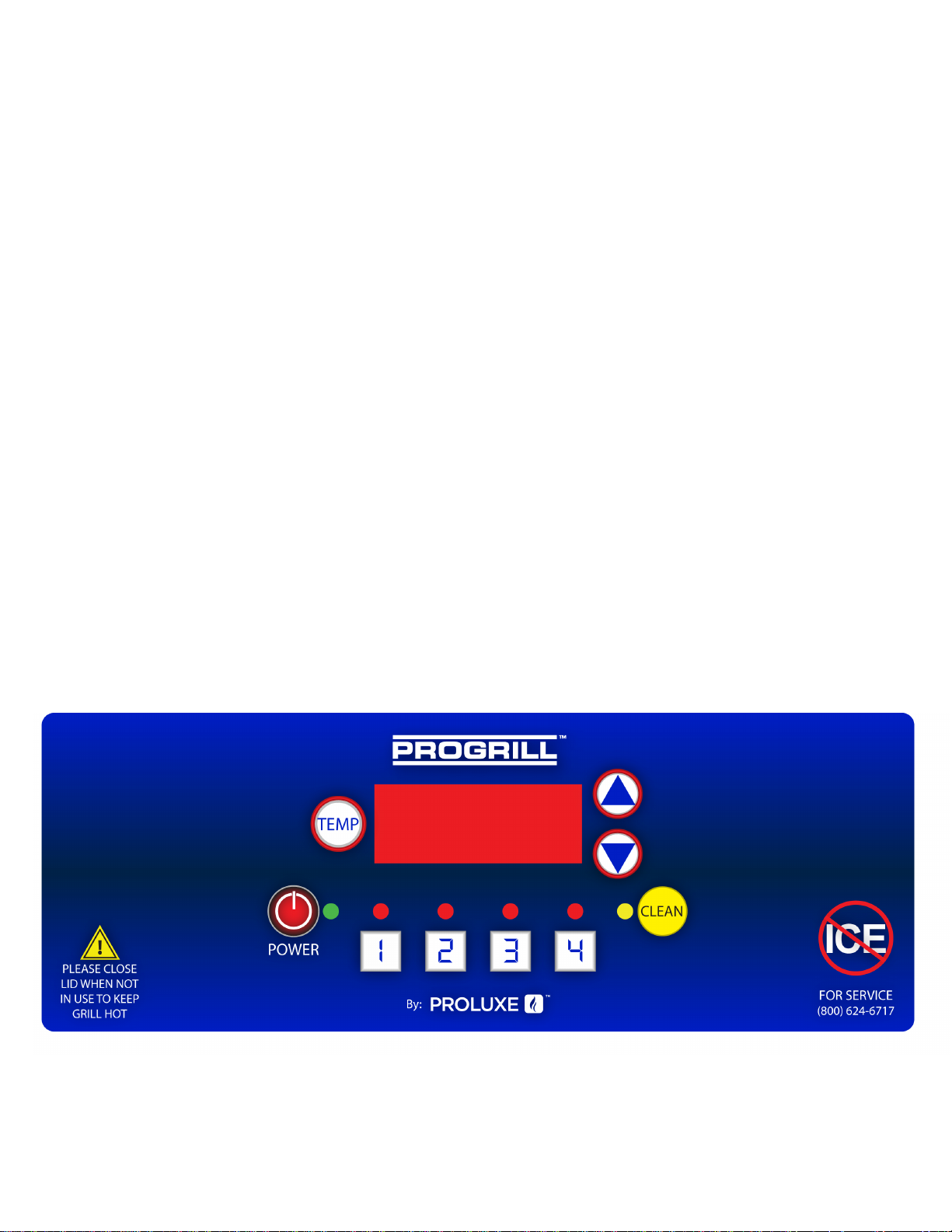
HOW TO FIND TEMPERATURE
1. To find the temperature of the UPPER PLATEN: Press the TEMPERATURE
button and the ARROW UP button at the same time.
2. To find the temperature of the LOWER PLATEN: Press the TEMPERATURE
button and the ARROW DOWN button at the same time
* 275° is the factory default temp for the CLEAN cycle. To change the CLEAN cycle temp,
simultaneously hold down the TEMP and CLEAN buttons for 15 seconds. The current temp setting will
display on the right digital display only. Using the up or down arrows to adjust to the desired temp.
CSD Operating Instructions:
1. Press desired time
reset the time cycle
2. If for any reason the timer has to be reset in the middle of a cycle, you must press and hold
to start the time cycle. After the cycle is finished, press it again to

Instruction’s for Adjusting the Temperature
PRESS and hold the TEMP and
ARROW up
buttons simultaneously for 15
seconds.
The current temperature setting
will display on the right
digital display only.
Using the ARROW buttons, you
may now adjust the temperature
to your
desired setting.
Once you have set your desired
temperature simply push
the TEMP button. The digital
displays will now read the
preset times.
Instructi
on’s for Adjusting the Set-Time
Press
desired timer button and continue to hold
both for 5 seconds.
The digital displays will now read their preset
times as shown here. Each side is capable of
having up to 4 different settings, making a total
of 8 set-times.
Now using the ARROW buttons you
can set your desired time.
Once you have set the desired time simply press the
TEMP button, the unit will display the new set-time.
*IMPORTANT NOTE: When adjusting the time settings, The RIGHT SIDE time buttons
control the left side, so the same time you set on the right will automatically be set to
the left side accordingly. If you desire an additional set of times you can adjust the left
side AFTER you have adjusted the right side without effecting the right side settings.
the TEMP button first and then the

A2
CSD1212A
10
13
2X
14
2X
A1
11
15
12
2X
2X
2X
2X
21
37
4X
3X
35
1
29
4X
16
72
4
23
2X
5
8
4X
9
4X
6
4X
20
2
7
12X
4X
2X
28
22
2X
2X
26
29
4X
27
4X
31
63
36
24
25
32
30
34
33
3X
EXPCSD1212A RF 012819
CUSTOMER MANUAL SHEET 1 OF 2

CSD1212A
3
61
2X
A3
72
4X
63
A4
62
38
40
2X
18
19
51
2X
A5
49
2X
47
45
2X
4X
67
52
48
58
4X
41
4X
64
46
59
50
2X
65
78
45
44
43
3X
3X
3X
60
2X
2X
2X
2X
70
72
52
68
42
69
76
71
3X
2X
2X
17
45
53
44
43
2X
73
46
3X
3X
2X
65
48
4X
75
45
64
63
2X
74
2X
66
67
12X
78
4X
77
4X
57
4X
56
55
54
50
2X
47
49
2X
40
51
2X
EXPCSD1212A RF 012819
CUSTOMER MANUAL SHEET 2 OF 2
39

PARTSLISTFORMODELCSD1212
A
ITEM
NO.
1
BASE FRAME ASSEMBLY PG115100 PG115100
DESCRIPTION MODEL CSD1212A
MODEL
CSD1212DT
2 FEET, RUBBER 3/4 11016546469 11016546469 4
3 POWER CORD, 120 VOLTS 1101217174 1101217174 1
4 LOWER PLATEN, INSULATION 11018344019 11018344019 1
5 LOWER PLATEN INSULATION COVER 11018344018 11018344018 1
6 SCREW, SET 3/8-16X 1-1/2 SST3816112 SST3816112 4
7 WASHER SAE 3/8 WSAE38 WSAE38 12
8 WASHER SPLIT LOCK WL38 WL38 4
9 NUT HEX 3/8-16 NH3816 NH3816 4
10 SHIM, LOWER PLATEN 11018344030 11018344030 1
11 GREEN INSULATION WASHER C4401 C4401 2
12 LOCK WASH 1/4 WL14 WL14 2
13 WASHER SAE 1/4 WSAE14 WSAE14 2
14 NUT, HEX 1/4-20 NH1420 NH1420 2
15 BOLT, HEX 1/4 - 20 X 1 BH14201 BH14201 2
16 RTD, BOTTOM SENSOR 1108881102 1108881102 1
17 BUSHING TEFLON 3/4 LONG 110113441 110113441 2
18 WIRE HARNESS PG115050 PG115050 1
19 CSD1212 OVERLAY OCSD1212B OCSD1212DTB 1
20 BOTTOM COVER WITH PEM NUTS 11018344022 11018344022 1
21 STOP, HEX PIN 11018344037 11018344037 2
22 SINK, HEAT, ALUMINUM (SSR) 11057322 11057322 2
23 SOLID STATE RELAY, 25 AMPS PL2425 PL2425 2
24
INSULATOR, TRANSFORMER 1101159180 1101159180
25 TRANSFORMER 11096975 11096975 1
26 SCREW, PHILLIPS PAN HEAD 8-32 X 1/4 SP83214 SP83214 2
27
MARKER STRIP #6 MS6016 MS6016
28 TERMINAL BLOCK #6, DOUBLE 6016 6016
29 SCREW, PAN HEAD PHILLIPS 8-32 X 1/2 SP83212 SP83212 6
30 FUSE HOLDER 1 AMP MPPF708 MPPF708 1
31 FUSE BUSS 1 AMP MPPF701R MPPF701R 1
32 SCREW, PHILLIPS PAN 2-56 X 1/4 SP25614 SP25614 1
33 SCREW, PHILLIPS PAN HEAD 8-32 X 1.0 SP8321 SP8321 1
34 WASHER, INTERNAL TOOTH LOCK #8 WLIT8 WLIT8 3
35 NUT, HEX 8-32 NH832 NH832 3
36 WASHER SAE #8 WSAE8 WSAE8 4
37 BUSHING FLANGED, TEFLON .500" 110115563 110115563 4
38 HANDLE LEFT ASSEMBLY 11018344027 11018344027 1
39 HANDLE RIGHT ASSEMBLY 11018344026 11018344026 1
40 HANDLE GRIP 110901168 110901168 2
41 CLEVIS ASSEMBLY LEFT HAND 11018344013 11018344013 1
42 CLEVIS ASSEMBLY RIGHT HAND 11018344012 11018344012 1
43 5/16 WASHER CUT WC516 WC516 6
44 WASHER, 5/16" SPLIT LOCK WL516 WL516 10
45 SCREW, SOCKET HD 5/16-18 X 3/4" SSH5161834 SSH5161834 6
46 SHIM, COVER 11018344014 11018344014 2
47 SPACER, LINK 11018344024 11018344024 2
48 LEVELING BRACKET 11018344023 11018344023 2
49 WASHER LOCK INTERNAL TOOTH 5/16 WLIT516 WLIT516 4
50 BUSHING, TEFLON, 3/4 I.D. X .875 X 1" LONG 110115541 110115541 4
51 5/16 - 18 x 1 SS., BOLT HEX HEAD BH516181S BH516181S 4
52 E-CLIP, RETAINING RING LCC3478 LCC3478 4
53 COVER, REAR 11018344016 11018344016 1
54 GREASE TRAY ASSY 11018344005 11018344005 1
55 DIGITAL CONTROL 110171433052 110171433052 1
56 WASHER, STEEL .311 O.D. X .150 I.D. 311150019 311150019 4
57 NYLON SPACER 1/4 X .141 X 9/32 11090109 11090109 4
58 WASHER, INTERNAL TOOTH LOCK #6
WLIT6 WLIT6
59 NUT, HEX 6-32 NH632 NH632 4
60 STRAIN RELIEF 1106546468 1106546468 1
61 UPPER PLATEN, INSULATION 11018344074C1 11018344074C1 2
62 TOP SHROUD 11019344010 11019344010 1
63 SCREW, PAN HEAD PHILLIPS 8-32 X 3/8 SS SP83238S SP83238S 12
64 TOP LINK 11018344017 11018344017 2
65 PIN, PIVOT FRONT 11017088865 11017088865 2
QTY.
1
1
1
1
4
PLCSD1212RF012819CUSTOMERMANUAL

PARTSLISTFORMODELCSD1212
66 SCREW, SET KNURKED CUP POINT 5/16-18 X 3/8 SST5161838KN SST5161838KN 12
67 RING RETAINING 3/8 11017088867 11017088867 8
68 PLUNGER ASSEMBLY 110115544 110115544 2
69 SPRING, DETENT 110115555 110115555 2
70 TUBING-PAD 110115531 110115531 2
71 SCREW, SET 3/8-16 x 1.00 SST38161 SST38161 2
72 SCREW, SET 3/8-16 X 1/2 SST381612 SST381612 4
73 COLLAR CAM 110115530 110115530 2
74 HANDLE SPRING ADJUSTING COLLAR 110115528 110115528 2
75 COUNTER BALANCE SPRING RIGHT HAND 1101023154R 1101023154R 1
76 COUNTER BALANCE SPRING LEFT HAND 1101023154L 1101023154L 1
77 RTD, TOP SENSOR 1108881101 1108881101 1
78 PIN, LEVELER REAR 11018344048 11018344048 2
79 MANUAL CSD1212 MCSD1212A MCSD1212DTA 1
A1 LOWER PLATEN WITH WIRING ONLY 11018344032120K 11018344032120K 1
LOWER PLATEN ASSEMBLY COMPLETE 11018344032120AK 11018344032120AK 1
A2
A3 UPPER PLATEN WITH WIRING ONLY 11019344074120K 11019344074120K 1
A4 UPPER PLATEN ASSEMBLY COMPLETE 11019344074120AK 11019344074120AK 1
A5
KITTED, CONTROLLER DIGITAL 110171433052K 110171433052K 1
PLCSD1212RF012819CUSTOMERMANUAL


Rev 12916
Warranty & Return Policy
Proluxe warrants all products manufactured by it against defects in workmanship or materials from the date of purchase for a period of
(1) year on parts and labor. This warranty applies to only equipment purchased and used in the United States. Warranty period
shall begin when equipment ships. Warranty travel shall only be covered for 60 miles. Limited lifetime warranty on heating
elements.
ALL WARRANTY SERVICE CALLS MUST BE APPROVED BY PROLUXE. IF THIS PROCEDURE IS NOT FOLLOWED,
WARRANTY SERVICE WILL NOT BE COVERED. WARRANTY SERVICE WILL BE PAID ON STRAIGHT TIME, OVERTIME WILL
NOT BE COVERED.
Exclusions:
1. WOOD / GAS FIRED OVENS: PROLUXE warranty applies to the main body of the oven being steel / refractory and insulation shall
be free from defects in materials and workmanship for a period of four years from the date of purchase. The gas equipment shall be
free from defects in materials and workmanship for a period of one (1) year
from the date of purchase. Lifetime warranty against cracks on oven floor.
2. Air compressors are excluded from this warranty, but PROLUXE may act as a warranty expeditor in certain instances regarding
these compressors. The air compressor manufacturer provides a limited warranty
and a copy of this warranty is furnished with all compressors sold by PROLUXE. For prompt handling of compressor warranty claims
the instructions of the compressor manufacturer must be adhered to.
3. Equipment built to special order as well as accessories cannot be canceled and are not returnable unless defective within the
terms of this warranty.
4. In no event shall PROLUXE be liable for consequential damages arising out of the failure of any of its products if operated
improperly or caused by normal wear or damage by operator abuse.
5. BC2325 pedestal warranty disclaimer: Pedestals shall only be covered under warranty if they have been cleaned using the factory
approved cleaning method. cracked or damaged pedestals must be inspected by the factory before warranty is authorized.
6. Limited lifetime warranty on heating elements: If replacement is needed, Proluxe will send the new part at no charge but labor will
not be covered unless the unit is still under the 1 year manufacture warranty.
Returned Merchandise Policy:
Should it become necessary to return any of the company’s products, the following instructions must be adhered to: First,
contact our customer service department for approval and a return authorization number. Please have the serial number
of your item available at that time. All merchandise must be shipped freight prepaid by customer or service agency.
Subject to the inspection of the product by the company, a restocking charge of 20% of the Net purchased price paid to
PROLUXE will be assessed. Merchandise may not be returned for credit without prior written approval of PROLUXE. Collect shipments
will not be accepted. No returns after 60 days of original shipment date on machines. Purchased parts may not be returned after 30
days.
If upon inspection by PROLUXE or its authorized agent it is determined the equipment has not been used in an appropriate manner,
has been modified, or has not been properly maintained, or has been subject to misuse,
misapplication, neglect, abuse, accident, unauthorized modification, damage during transit, delivery, fire, flood, act or war,
riot or act of God, then this warranty shall be deemed null and void.
Terms & Conditions:
1. Prices indicated in the PRICE LIST are suggested retail prices and are shown in U.S. DOLLARS.
2. Terms of Payment: 1% 10 days, NET 30 days.
3. NEW ACCOUNTS: Satisfactory credit information must be provided before open account status can be extended.
Unless agreed otherwise, all shipments will be made C.O.D., CASH IN ADVANCE.
4. PRICING: Prices, specifications, model numbers, capacities and accessories are subject to change without notice.
5. FREIGHT / ROUTING: Method of shipment will be determined by PROLUXE unless otherwise
advised by PURCHASER.
6. DAMAGED CLAIMS: All merchandise shipped at purchaser’s risk. Inspection must be made by purchaser at time
goods are received. If goods are damaged, the PURCHASER shall request that the agent of the transportation
company make a written notation on the proper shipping documents immediately and then file a claim for damage.
GOODS DAMAGED IN SHIPMENT ARE NOT RETURNABLE.
7. RETURNS: Machines may not be returned after 60 days. Purchased parts may not be returned after 30 days. A
restocking fee of 20% will be assessed on non-warranty returns.
8. TAXES: Prices indicated herein DO NOT include State, Federal, Local or foreign taxes or duties, nor do they include
fees, permits, insurance or other levies, all of which are the responsibility of the purchaser.
9. All orders are subject to acceptance by PROLUXE.
10. Possession of this price list shall not be considered an offer to sell.
 Loading...