


Operations Manual
Model: CS157PHNA
15”x 7” Clamshell Grill
formerly DOUGHPRO. New Name. Same Quality. Superior Service.
proluxe.com

Operation Instructions
Please read carefully before attempting to use this appliance.
Step 1. Carefully unpack and clean grill plates with mild soap then sponge clean
with cold water.
Step. 2. Place in location where it will be used allowing for clearances per the
dimensions indicated.
WARNING! Allow 2” minimum clearance between adjacent equipment and/or
wall areas.
Do not touch hot surfaces.
Step 3. Plug into proper 3 prong wall outlet. If other appliances are connected
to the same circuit make sure the total load does not exceed maximum
ampacity of the circuit. Electrical information is as follows:
120V/60Hz/1 phase/1150W/9.6 Amps
208V/60Hz/1 phase/2800W/13.5 Amps
Step 4: Warm-up
on. The display flashes and shows left preset timer during warm-up. Pre heat temperature time will be 40-50 minutes. When the set point is
reached, the display stops flashing and beeps 3 times.
Step 4: Operation
Energize by turning on the power switch which will illuminate when turned
Simply place product on grill, close lid and press the
desired pre-set time cycle (ex: 10 seconds). After the time cycle is
finished press it again to reset the time cycle.
Cleaning Instructions
NOTE! Always turn off power and allow to cool down before attempting to clean.
Never submerge grill in water or other liquid nor use mineral spirits
or other flammable material to clean this appliance.
!Never use ice to cool down grill, warranty will be void!
Clean stainless steel and griddle surfaces with soap and water using a
soft, clean cloth periodically as required, but at least once daily. Never
use harsh abrasives. Use only non-abrasive scouring pads when required.

Clean Cycle
275°F is the factory default temp for the CLEAN cycle. To change the CLEAN cycle temp, simultaneously
hold down the TEMP and CLEAN buttons for 15 seconds.
Using the up or down arrows to adjust to the desired temp.
To start a clean cycle, push CLEAN button once so the CLEAN LED light is turned on. All preset LED’s are
turned off, and the temperature set point is changed to the clean set point of 275°F. This also initiates
the cool down to clean set point condition as well the display starts flashing until the clean set point is
reached.
To stop the clean cycle, simply press the CLEAN button once to deactivate the clean cycle. The CLEAN
LED is turned off, the preset LED’s are restored, the temperature set point is changed to the main set
point. Again, the warm-up condition is initiated and the display flashes until the cook set point is
reached.
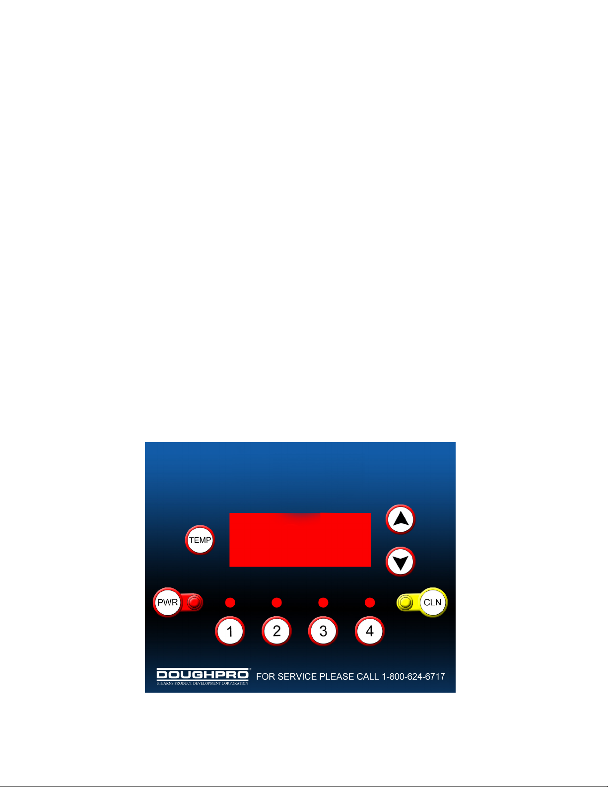
HOW TO FIND TEMPERATURE
1. To find the temperature of the UPPER PLATEN: Press the TEMPERATURE
button and the ARROW UP button at the same time.
2. To find the temperature of the LOWER PLATEN: Press the TEMPERATURE
button and the ARROW DOWN button at the same time
* 275° is the factory default temp for the CLEAN cycle. To change the CLEAN cycle temp,
simultaneously hold down the TEMP and CLEAN buttons for 15 seconds. The current temp setting will
display on the right digital display only. Using the up or down arrows to adjust to the desired temp.
CS157 Operating Instructions:
1. Press des
reset the time cycle
2. If for any reason the timer has to be reset in the middle of a cycle, you must press and hold
ired time to start the time cycle. After the cycle is finished, press it again to

Instruction’s for Adjusting the Temperature
PRESS and hold the TEMP and
ARROW up
buttons simultaneously for 15
seconds.
Using the ARROW buttons, you
may now adjust the temperature
to your desired setting.
Once you have set your desired
temperature simply push
the TEMP button. The digital
displays will now read the
preset times.
Instruction’s for Adjusting the Set-Time
PRESS the desired button you
wish to program.
Now press BOTH button and
TEMP buttons simultaneously
for 5 seconds.
The digital displays will now read their preset
time. The unit is capable of having
up to 4 different settings.
Now using the ARROW buttons you
can set your desired time.
Once you have set the desired time simply press the
TEMP button, the unit will display the new set-time.

DOUGHPRO
CS157 Clamshell Grill Trouble Shooting Guide
Symptom Probable Cause Action to be Taken Parts List Ref. #
Power Button on Control face is
depressed but doesn’t turn on.
Power Cord is not plugged in.
Plug power cord into wall 's
receptacle and depress power
button on controller
9
Circuit Breaker is tripped off in the
site's breaker box
Reset circuit breaker that the Grill is
plugged into. Depress Power Button
to turn on.
___
Transformer has taken a electrical
surge and is damaged
Replace Transformer
6
Check voltage on the secondary side
of the Transformer. If you read
12VDC then you are receiving voltage
to the Controller.
Replace Controller. Controller
should be on once the power button
is depressed.
58
Possibly blown Fuse Check fuse and repace if necessary
5
Digital Controller's LED's are
scrambled or randomly irratic
Possibly a componet on the Digital
Controller is damaged
Replace the Digital Controller.
58
Possibly control needs to reset
While unit is on (controller lit up)
Unplug unit, wait for 1 min. then
plug machine on and depress power
button.
___
Digital Controller is constantly
Beeping No heat on either on left
right Upper, or Lower Platen.
Depress Temp. While depressing
Temp., depress either up or down
arrow to locate error
message,"PROB" (zone 1, Lower
Platen, zone 2 Left Upper Platen,
zone 3, right Upper Platen.) . If
occurred when depressing the up
arrow indicates either the left or
right Upper Platen has the open
sensor or probe. same goes for the
down arrow indicating Lower Platen.
Sensor in one of two zones lost it's
continuity. Depress Temp. While
depressing Temp., depress either up
or down arrow to locate error
message,"PROB" (zone 1, Lower
Platen, zone 2 Left Upper Platen,
zone 3, right Upper Platen.) . If
occurred when depressing the up
arrow indicates either the left or right
Upper Platen has the open sensor or
probe. same goes for the down
arrow indicating Lower Platen
Disconnect prob and check for
continuity (by using Ohm Meter) and
replace. Do not cut and splice new
sensor. Install new 2000 ohm RTD
sensor to under side of Heat Platen
and reconnect to Controller. Upper
left and right sensor for replacement
on upper platens, Lower Platen
sensor for replacement for Lower
Platen.
69
Digital Controller is beeper chirping
and is over heating.
The Mechanical Relay on the
switched side is not opening to
regulate temperture. Same as above,
hold Temp button then depress
either the down or up arrow (zone 1,
Lower Platen, zone 2 Left Upper
Platen, zone 3, right Upper Platen.)
which ever zone is the problem, you
will see RLY indicating the damage (in
closed position) .
Replace the Mechanical Relay.
#15
One of the three Heater Platens not
close to set point.
The offset function in the Controller's
setting needs to be adjusted to
achieve proper shade of toast.
Call Doughpro (800) 624-6717 for
instructions. This information must
not to be given to operators of the
Carmelizer. They may get confused
and cause further temperature
discrepancies.
____
Beeper not functioning Beeper has failing. Replace Controller board
# A8

DOUGHPRO
CS157 Clamshell Grill Trouble Shooting Guide
Symptom Probable Cause Action to be Taken Parts List Ref. #
Either Heater Platen is not Heating
but the Digital Controller is on and
appears to be functioning.
If the Mechanical Relay (s) on the coil
side are receiving 12vdc indicates the
Controller is functioning properly. On
the switching side of the relay, is the
rated voltage for the Model(120,208,
or 220~AC) going to the heater in
question? If there is no voltage on
the to the switching side of the relay
to the heaters, the Relay is not
working properly
Replace Mechanical Relay.
# 15
Heater Platen overheating
The mechanical Relay may be stuck in
the closed position (zone 1, Lower
Platen #1 labeled on this relay, zone
2, left upper and zone 3, right upper).
Replace Mechanical Relay(s).
33
If you are receiving 12vdc on the coil
of the relay, the Controller is properly
functioning thus maybe you have a
break in the wire to the heater (s) or
the Heater Platen lost it's continuity
One of the Heater's embedded into
to the Heated Aluminum Platen may
have lost Continuity. With use of a
Ohm Meter a condinuity check must
check at the cold pins of the heater
(where the heater wire is brazed at
the cold pin. This will eliminate any
other failue before the the heater
element validating the loss off
condinuity at the source (Heater
Element). If so, either the Upper left
A6 or A6P
Either Upper Heater not coming
down parallel to the Lower Heater
Platen.
Parallel Lever not attached either in
the rear out on the Upper Heater
Platen. Check to see if Parallel leveler
is connected on both sides. The
retaining clip attached to pin may
have come off.
Reconnect the pin and the retaining
E-Clip.
17
Upper Platen falling down or lost It's
retension .
Possibly the Springs (2, one for each
Upper Heater Platen has lost some
retension.
Remove rear panel and adjust the
retaining collars on shaft by winding
spring tighter. There are mutlple set
screws that need to be loosened in
order to wind the spring tighter.
Once achieving proper tension be
sure to tighten all set screws so that
tension isn't lost again.
65 & 63
If one heating zone is not reaching
setpoint and another heater is
overheating
Sensors maybe crossed
Make sure each sensor is connected
to it's prospective postion on the
terminal block which in turn to the
Controller.
___

MODEL CS157PHN
55
14
56
57
76
23
79
51
54
A1P
91
A2P
52
36
1868
12
11
24
88
14
1
14
44
53
45
EXPCS157PHN RA 1000 060414
SHEET 1 OF 3

MODEL CS157PHN
A5
60
10
3
A3P
75
52
54
51
69
78
51
21
20
64
20
63
66
37
36
50
42
41
17
37
73
37
17
13
19
72
EXPCS157PHN RA 1000 060414
SHEET 2 OF 3

MODEL CS157PHN
49
67
77
A4P
22
65
17
17
62
84
A6
46
43
58
38
27
4
43
46
48
5
30
33
8
29
43
46
6
89
90
28
32
29
28
32
29
70
48
9
83
61
31
43
46
7
40
16
42
47
84
82
15
84
84
34
EXPCS157PHN RA 1000 060414
47
SHEET 3 OF 3

PARTLISTFORTHE
6
0969
13
GREASE TRAY
110103903
1
21
RUBBER GROMET, 5/16 X 1/2
110115554
1
30
SCREW, PAN HEAD PHILLIPS 2 56
X 1/4
SP25614
1
40
MARKER STRIP #6 DOUBLE
MS6016
1
7
SC
S 8-32X3/8 S
SS S
SP83238S
3
7
SC , S 8 3 3/8 S SS S
S 83 38S
3
55
BOLT, HEX 1/4-20 x 1 STAINLESS STEEL
BH14201S
1
CS157PHN
ITEM #
1 LOWER WRAP AROUND SHROUD ASSEMBLY 110103901 1
3 SPRING, DETENT1/2 LONG 110115555 1
4 FUSE HOLDER MPPF708 1
5 FUSE BUSS 1 AMP MPPF701R 1
TRANSFORMER 11
7 TERMINAL BLOCK #6 6016 1
8 STRAIN FELIEF 11016546468 1
9 CORD, POWER 120V 110969174 1
10 TUBBING-PAD 110115531 1
11 COVER, LOWER PLATTEN ASSEMBLY 110103909 1
12 LOWER PLATEN INSULATION 110103910 1
14 GREEN INSULATION WASHER C4401 9
15 TOP LINK 110115508 1
16 BOLT, HEX 5/16-18 X1 STAINLESS STEEL BH516181S 2
17 E-CLIP, RETAINING RING LCC3478 2
18 PIN, BACK STOP 110115543 1
19 HANDLE GRIP 110901168 1
20 SCREW, SET KNURLED CUP POINT 5/16-18 x 3/8 SST5161838KN 6
DESCRIPTION
MODEL
CS157PHNA
120V
75 1
QTY.
22 INSULATION, UPPER PLATEN RIGHT HAND 110888251R 1
23 BUSHING, TEFLON , 3/4 110113441 1
24 GROMET, RUBBER 3/4 X 1 3/8 110103919 1
27 SPACER, NYLON 1/4X.141 X 9/32 11090109 4
28 WASHER, SAE #8 WSAE8 4
29 NUT, HEX 8-32 NH832 3
31 WASHER, INTERNAL TOOTH LOCK 5/16 WLIT516 2
32 WASHER, INTERNAL TOOTH LOCK #8 WLIT8 2
33 RELAY 110942520 2
34 BOTTOM COVER 110103917 1
36 FLANGE TEFLON BUSHING 1/2 110115563 1
37 BUSHING TEFLON 1" 110115541 3
38 WASHER, STEEL 311150019 4
41 WASHER, CUT 5/16 WC516 3
42 WASHER, SPLIT LOCK 5/16 WL516 5
43 WASHER, INTERNAL TOOTH LOCK #6 WLIT6 12
44 WASHER, SAE 3/8 WSAE38 4
45 NUT, HEX 3/8-16 NH3816 4
46 NUT, HEX 6-32 NH632 12
4
48 SCREW, PHILLIPS 6-32X3/8 SP63238 6
49 SCREW, PAN HEAD SLOTED 10-32 X 3/8 STAINLESS STEEL SPS103238S 6
50 SCREW, SOCKED HEAD 5/16-18 X 3/4 SSH5161834 3
51 SCREW, SET 3/8-16 X 1/2 SST381612 3
52 SCREW, PAN HEAD PHILLIPS 6-32 X 1/4 SP63214 2
53 WASHER, SPLIT LOCK 3/8 WL38 4
54 WASHER, SAE #6 WSAE6 2
REW, PHILLIP
TAINLE
TEEL
1
56 WASHER, SAE 1/4 WSAE14 1
57 WASHER, SPLIT LOCK 1/4 WL14 1
PLCS157PHNRA1000060414

PARTLISTFORTHE
63
G C
O
28
70
SCREW, PAN HEAD PHILLIPS 8 32
X 1
SP8321
1
82
PIN, PIVOT BACK
110115566
1
91
LOWER PLATEN
110103932P
1
CS157PHN
ITEM #
DESCRIPTION
58 DIGITAL CONTROL 1101029052 1
60 PLUNGER ASSEMBLY 110115544 1
61 UPPER LEVELING BRACKET 110115510 1
62 UPPER LEVELING SHIM 110115557 1
HANDLE, SPRING ADJUSTIN
LLAR 1101155
64 COLLAR, HOLDER 110115530 1
65 BACK COVER 110103907 1
66 COUNTER BALANCE SPRING 1101039154 1
67 RIGHT SHROUD ASSY 11016546457 1
68 RTD SENSOR 1108881102 1
69 RTD SENSOR 1108881101 1
72 HANDLE RIGHT ASSEMBLY 110103916 1
73 CLEVIS ASSY, RIGHT HAND 110115504 1
75 SST SET SCREW 3-8-16 X 1 SST38161 1
76 NUT, SERRATED FLANGED HEX 1/4-20 NHSF1420 1
77 OVERLAY OCS157PHN 1
78 UPPER PLATEN, RIGHT 110115540R120 1
79 WIRE HARNESS 110103950 1
MODEL
CS157PHNA
120V
QTY.
1
83 PIN, PIVOT FRONT 110115565 1
84 RETAINING RING 110115567 4
87 MANUAL CS157 MSCS157 1
88 SCREW, SET 3/8-16 X 1 1/2 SST3816112 4
89 TRANSFORMER INSULATION 1101159180 1
90 SCREW, PHILLIPS 6-32X5/8 SP63258 2
A1P
A2P
A3P
A4P
A5
A6
LOWER PLATEN PANINI WITH WIRING 110103932307
LOWER PLATEN PANINI ASSEMBLY 110103932PK
UPPER PLATEN PANINI RIGHT HAND WITH WIRING 1101155304
UPPER PLATEN PANINI RIGHT HAND ASSEMBLY 1101155313
SCRAPER, PANINI 110115580
KITTED, PROGRAMMED CONTROLLER TEMPERATURE ASSEMBLY
1101029052K 1
1
1
1
1
1
PLCS157PHNRA1000060414


PLEASE READ CAREFULLY BEFORE ATTEMPTING TO USE THIS APPLIANCE.
LIMITED MACHINE WARRANTY
WHAT IS COVERED
Doughpro warrants the CS157, from manufacturing defects in workmanship and material sold within
the domestic United States.
HOW LONG DOES THE COVERAGE LAST
One year warranty for parts and labor. The heating elements on the upper and lower platens have
a limited lifetime warranty on the elements.
WHAT WE WILL DO
We will repair or replace the defective CS157 on normal warranty one year parts and labor. The
heating elements on the upper and lower platen only; will be replaced by next day air service;
under the normal one year warranty. Such repair or replacement will be at the expense of
Doughpro on under the normal one year warranty.
HOW TO GET SERVICE
Contact our Factory to obtain warranty service. Doughpro must issue a return authorization
number, and call tag, or find the name and location of a Factory Authorized Service Center
nearest you. When calling for service, please furnish the model number, serial number, and a
description of the problem.
WHAT THIS WARRANTY DOES NOT COVER
THE WARRANTIES PROVIDED BY DOUGHPRO DO NOT APPLY IN THE FOLLOWING
INSTANCES:
*Do not * Do not apply ice to grill surface as this will cause it to warp and void the warranty. Do
not use abrasive cleaners not specified by Doughpro .Do not use abrasive material such as grill
blocks or metallic scrubbers to clean the grill surface. Do not place unit in sink to wash down or
apply water to the unit
• Damage due to misuse, abuse, alteration, or accident.
• Improper or unauthorized repairs.
• Submerged in water.
• Dropped.
• Damage in shipment.
• Equipment exported to foreign countries.

Rev 12916
Warranty & Return Policy
Proluxe warrants all products manufactured by it against defects in workmanship or materials from the date of purchase for a period of
(1) year on parts and labor. This warranty applies to only equipment purchased and used in the United States. Warranty period
shall begin when equipment ships. Warranty travel shall only be covered for 60 miles. Limited lifetime warranty on heating
elements.
ALL WARRANTY SERVICE CALLS MUST BE APPROVED BY PROLUXE. IF THIS PROCEDURE IS NOT FOLLOWED,
WARRANTY SERVICE WILL NOT BE COVERED. WARRANTY SERVICE WILL BE PAID ON STRAIGHT TIME, OVERTIME WILL
NOT BE COVERED.
Exclusions:
1. WOOD / GAS FIRED OVENS: PROLUXE warranty applies to the main body of the oven being steel / refractory and insulation shall
be free from defects in materials and workmanship for a period of four years from the date of purchase. The gas equipment shall be
free from defects in materials and workmanship for a period of one (1) year
from the date of purchase. Lifetime warranty against cracks on oven floor.
2. Air compressors are excluded from this warranty, but PROLUXE may act as a warranty expeditor in certain instances regarding
these compressors. The air compressor manufacturer provides a limited warranty
and a copy of this warranty is furnished with all compressors sold by PROLUXE. For prompt handling of compressor warranty claims
the instructions of the compressor manufacturer must be adhered to.
3. Equipment built to special order as well as accessories cannot be canceled and are not returnable unless defective within the
terms of this warranty.
4. In no event shall PROLUXE be liable for consequential damages arising out of the failure of any of its products if operated
improperly or caused by normal wear or damage by operator abuse.
5. BC2325 pedestal warranty disclaimer: Pedestals shall only be covered under warranty if they have been cleaned using the factory
approved cleaning method. cracked or damaged pedestals must be inspected by the factory before warranty is authorized.
6. Limited lifetime warranty on heating elements: If replacement is needed, Proluxe will send the new part at no charge but labor will
not be covered unless the unit is still under the 1 year manufacture warranty.
Returned Merchandise Policy:
Should it become necessary to return any of the company’s products, the following instructions must be adhered to: First,
contact our customer service department for approval and a return authorization number. Please have the serial number
of your item available at that time. All merchandise must be shipped freight prepaid by customer or service agency.
Subject to the inspection of the product by the company, a restocking charge of 20% of the Net purchased price paid to
PROLUXE will be assessed. Merchandise may not be returned for credit without prior written approval of PROLUXE. Collect shipments
will not be accepted. No returns after 60 days of original shipment date on machines. Purchased parts may not be returned after 30
days.
If upon inspection by PROLUXE or its authorized agent it is determined the equipment has not been used in an appropriate manner,
has been modified, or has not been properly maintained, or has been subject to misuse,
misapplication, neglect, abuse, accident, unauthorized modification, damage during transit, delivery, fire, flood, act or war,
riot or act of God, then this warranty shall be deemed null and void.
Terms & Conditions:
1. Prices indicated in the PRICE LIST are suggested retail prices and are shown in U.S. DOLLARS.
2. Terms of Payment: 1% 10 days, NET 30 days.
3. NEW ACCOUNTS: Satisfactory credit information must be provided before open account status can be extended.
Unless agreed otherwise, all shipments will be made C.O.D., CASH IN ADVANCE.
4. PRICING: Prices, specifications, model numbers, capacities and accessories are subject to change without notice.
5. FREIGHT / ROUTING: Method of shipment will be determined by PROLUXE unless otherwise
advised by PURCHASER.
6. DAMAGED CLAIMS: All merchandise shipped at purchaser’s risk. Inspection must be made by purchaser at time
goods are received. If goods are damaged, the PURCHASER shall request that the agent of the transportation
company make a written notation on the proper shipping documents immediately and then file a claim for damage.
GOODS DAMAGED IN SHIPMENT ARE NOT RETURNABLE.
7. RETURNS: Machines may not be returned after 60 days. Purchased parts may not be returned after 30 days. A
restocking fee of 20% will be assessed on non-warranty returns.
8. TAXES: Prices indicated herein DO NOT include State, Federal, Local or foreign taxes or duties, nor do they include
fees, permits, insurance or other levies, all of which are the responsibility of the purchaser.
9. All orders are subject to acceptance by PROLUXE.
10. Possession of this price list shall not be considered an offer to sell.
 Loading...