

Page 1

AssuredSAN Ultra48 Series
Setup Guide
Abstract
This document describes initial hardware setup for Dot Hill AssuredSAN Ultra48 Series controller enclosures, and is intended for use
by storage system administrators familiar with servers and computer networks, network administration, storage system installation
and configuration, storage area network management, and relevant protocols.
P/N 83-00006723-10-01
Revision A
April 2014
Page 2

Copyright © 2014 Dot Hill Systems Corp. All rights reserved. Dot Hill Systems Corp., Dot Hill, the Dot Hill logo, AssuredSAN, AssuredSnap,
AssuredCopy, AssuredRemote, R/Evolution, and the R/Evolution logo are trademarks of Dot Hill Systems Corp. All other trademarks and registered
trademarks are proprietary to their respective owners.
The material in this document is for information only and is subject to change without notice. While reasonable efforts have been made in the
preparation of this document to assure its accuracy, changes in the product design can be made without reservation and without notification to its
users.
Page 3

Contents
About this guide. . . . . . . . . . . . . . . . . . . . . . . . . . . . . . . . . . . . . . . . . . . . . . . . . . . . . . 11
Overview. . . . . . . . . . . . . . . . . . . . . . . . . . . . . . . . . . . . . . . . . . . . . . . . . . . . . . . . . . . . . . . . . . . . . 11
CNC ports used for host connection . . . . . . . . . . . . . . . . . . . . . . . . . . . . . . . . . . . . . . . . . . . . . . . . 11
HD mini-SAS ports used for host connection . . . . . . . . . . . . . . . . . . . . . . . . . . . . . . . . . . . . . . . . . . 12
Intended audience . . . . . . . . . . . . . . . . . . . . . . . . . . . . . . . . . . . . . . . . . . . . . . . . . . . . . . . . . . . . . . 12
Prerequisites. . . . . . . . . . . . . . . . . . . . . . . . . . . . . . . . . . . . . . . . . . . . . . . . . . . . . . . . . . . . . . . . . . . 12
Related documentation . . . . . . . . . . . . . . . . . . . . . . . . . . . . . . . . . . . . . . . . . . . . . . . . . . . . . . . . . . . 12
Document conventions and symbols . . . . . . . . . . . . . . . . . . . . . . . . . . . . . . . . . . . . . . . . . . . . . . . . . . 13
1 Components . . . . . . . . . . . . . . . . . . . . . . . . . . . . . . . . . . . . . . . . . . . . . . . . . . . . . . 15
Front panel components . . . . . . . . . . . . . . . . . . . . . . . . . . . . . . . . . . . . . . . . . . . . . . . . . . . . . . . . . . 15
48-drive enclosure front panel components . . . . . . . . . . . . . . . . . . . . . . . . . . . . . . . . . . . . . . . . . . . 15
Enclosure bezel installed . . . . . . . . . . . . . . . . . . . . . . . . . . . . . . . . . . . . . . . . . . . . . . . . . . . . . 15
Enclosure bezel removed . . . . . . . . . . . . . . . . . . . . . . . . . . . . . . . . . . . . . . . . . . . . . . . . . . . . . 16
Enclosure drawers . . . . . . . . . . . . . . . . . . . . . . . . . . . . . . . . . . . . . . . . . . . . . . . . . . . . . . . . . . . . 16
Disk drives used in Ultra48 Series enclosures . . . . . . . . . . . . . . . . . . . . . . . . . . . . . . . . . . . . . . . . . 17
Controller enclosure — rear panel layout. . . . . . . . . . . . . . . . . . . . . . . . . . . . . . . . . . . . . . . . . . . . . . . 18
4844 controller module — rear panel components . . . . . . . . . . . . . . . . . . . . . . . . . . . . . . . . . . . . . 19
4544 controller module — rear panel components . . . . . . . . . . . . . . . . . . . . . . . . . . . . . . . . . . . . . 20
4144 drive enclosure rear panel components . . . . . . . . . . . . . . . . . . . . . . . . . . . . . . . . . . . . . . . . . . . 20
Component installation and replacement . . . . . . . . . . . . . . . . . . . . . . . . . . . . . . . . . . . . . . . . . . . . . . . 20
Cache . . . . . . . . . . . . . . . . . . . . . . . . . . . . . . . . . . . . . . . . . . . . . . . . . . . . . . . . . . . . . . . . . . . . . . . 21
CompactFlash . . . . . . . . . . . . . . . . . . . . . . . . . . . . . . . . . . . . . . . . . . . . . . . . . . . . . . . . . . . . . . . . . 21
Supercapacitor pack. . . . . . . . . . . . . . . . . . . . . . . . . . . . . . . . . . . . . . . . . . . . . . . . . . . . . . . . . . . . . 22
2 Installing the enclosures. . . . . . . . . . . . . . . . . . . . . . . . . . . . . . . . . . . . . . . . . . . . . . . 23
Installation checklist . . . . . . . . . . . . . . . . . . . . . . . . . . . . . . . . . . . . . . . . . . . . . . . . . . . . . . . . . . . . . 23
Populating drawers . . . . . . . . . . . . . . . . . . . . . . . . . . . . . . . . . . . . . . . . . . . . . . . . . . . . . . . . . . . . . . 24
Opening and closing a drawer . . . . . . . . . . . . . . . . . . . . . . . . . . . . . . . . . . . . . . . . . . . . . . . . . . . 24
Aligning an AMS or disk module for installation into a drawer . . . . . . . . . . . . . . . . . . . . . . . . . . . . . 25
Installing an AMS . . . . . . . . . . . . . . . . . . . . . . . . . . . . . . . . . . . . . . . . . . . . . . . . . . . . . . . . . . . . 26
Installing a disk module . . . . . . . . . . . . . . . . . . . . . . . . . . . . . . . . . . . . . . . . . . . . . . . . . . . . . . . . 26
FDE considerations . . . . . . . . . . . . . . . . . . . . . . . . . . . . . . . . . . . . . . . . . . . . . . . . . . . . . . . . . 27
Connecting the controller enclosure and drive enclosures. . . . . . . . . . . . . . . . . . . . . . . . . . . . . . . . . . . . 28
Connecting the Ultra48 Series controller to the 4144 drive enclosure. . . . . . . . . . . . . . . . . . . . . . . . . 29
Cable requirements for storage enclosures . . . . . . . . . . . . . . . . . . . . . . . . . . . . . . . . . . . . . . . . . . . 29
Summary of drive enclosure cabling illustrations . . . . . . . . . . . . . . . . . . . . . . . . . . . . . . . . . . . . . 29
Testing enclosure connections. . . . . . . . . . . . . . . . . . . . . . . . . . . . . . . . . . . . . . . . . . . . . . . . . . . . . . . 31
Powering on/powering off. . . . . . . . . . . . . . . . . . . . . . . . . . . . . . . . . . . . . . . . . . . . . . . . . . . . . . . . . 31
AC PSUs. . . . . . . . . . . . . . . . . . . . . . . . . . . . . . . . . . . . . . . . . . . . . . . . . . . . . . . . . . . . . . . . . . . 31
Connect power cord to AC power supply . . . . . . . . . . . . . . . . . . . . . . . . . . . . . . . . . . . . . . . . . 32
Power cycle . . . . . . . . . . . . . . . . . . . . . . . . . . . . . . . . . . . . . . . . . . . . . . . . . . . . . . . . . . . . . . 32
3 Connecting hosts . . . . . . . . . . . . . . . . . . . . . . . . . . . . . . . . . . . . . . . . . . . . . . . . . . . 33
Host system requirements. . . . . . . . . . . . . . . . . . . . . . . . . . . . . . . . . . . . . . . . . . . . . . . . . . . . . . . . . . 33
Cabling considerations . . . . . . . . . . . . . . . . . . . . . . . . . . . . . . . . . . . . . . . . . . . . . . . . . . . . . . . . . . . 33
Connecting the enclosure to hosts . . . . . . . . . . . . . . . . . . . . . . . . . . . . . . . . . . . . . . . . . . . . . . . . . . . . 33
CNC technology . . . . . . . . . . . . . . . . . . . . . . . . . . . . . . . . . . . . . . . . . . . . . . . . . . . . . . . . . . . . . 33
Fibre Channel protocol . . . . . . . . . . . . . . . . . . . . . . . . . . . . . . . . . . . . . . . . . . . . . . . . . . . . . . 34
10GbE iSCSI protocol . . . . . . . . . . . . . . . . . . . . . . . . . . . . . . . . . . . . . . . . . . . . . . . . . . . . . . 34
1 Gb iSCSI protocol . . . . . . . . . . . . . . . . . . . . . . . . . . . . . . . . . . . . . . . . . . . . . . . . . . . . . . . . 35
HD mini-SAS technology . . . . . . . . . . . . . . . . . . . . . . . . . . . . . . . . . . . . . . . . . . . . . . . . . . . . . . . . 35
12 Gb mini-SAS ports . . . . . . . . . . . . . . . . . . . . . . . . . . . . . . . . . . . . . . . . . . . . . . . . . . . . . . . 35
Connecting direct attach configurations . . . . . . . . . . . . . . . . . . . . . . . . . . . . . . . . . . . . . . . . . . . . . 35
AssuredSAN Ultra48 Series Setup Guide 3
Page 4

Fibre Channel host connection . . . . . . . . . . . . . . . . . . . . . . . . . . . . . . . . . . . . . . . . . . . . . . . . . 35
10GbE iSCSI host connection. . . . . . . . . . . . . . . . . . . . . . . . . . . . . . . . . . . . . . . . . . . . . . . . . . 35
1 Gb iSCSI host connection . . . . . . . . . . . . . . . . . . . . . . . . . . . . . . . . . . . . . . . . . . . . . . . . . . . 36
HD mini-SAS host connection . . . . . . . . . . . . . . . . . . . . . . . . . . . . . . . . . . . . . . . . . . . . . . . . . . 36
Dual-controller configurations . . . . . . . . . . . . . . . . . . . . . . . . . . . . . . . . . . . . . . . . . . . . . . . . . . 36
Connecting switch attach configurations . . . . . . . . . . . . . . . . . . . . . . . . . . . . . . . . . . . . . . . . . . . . . 38
Dual-controller configuration. . . . . . . . . . . . . . . . . . . . . . . . . . . . . . . . . . . . . . . . . . . . . . . . . . . 38
Connecting a management host on the network . . . . . . . . . . . . . . . . . . . . . . . . . . . . . . . . . . . . . . . . . . 40
Connecting two storage systems to replicate volumes . . . . . . . . . . . . . . . . . . . . . . . . . . . . . . . . . . . . . . 40
Cabling for replication . . . . . . . . . . . . . . . . . . . . . . . . . . . . . . . . . . . . . . . . . . . . . . . . . . . . . . . . . 41
CNC ports and replication . . . . . . . . . . . . . . . . . . . . . . . . . . . . . . . . . . . . . . . . . . . . . . . . . . . . . . 41
Dual-controller configuration. . . . . . . . . . . . . . . . . . . . . . . . . . . . . . . . . . . . . . . . . . . . . . . . . . . 42
Updating firmware . . . . . . . . . . . . . . . . . . . . . . . . . . . . . . . . . . . . . . . . . . . . . . . . . . . . . . . . . . . . . . 45
Obtaining IP values . . . . . . . . . . . . . . . . . . . . . . . . . . . . . . . . . . . . . . . . . . . . . . . . . . . . . . . . . . . . . 45
Setting network port IP addresses using DHCP. . . . . . . . . . . . . . . . . . . . . . . . . . . . . . . . . . . . . . . . . 45
Setting network port IP addresses using the CLI port and cable . . . . . . . . . . . . . . . . . . . . . . . . . . . . . 45
Change the CNC port mode . . . . . . . . . . . . . . . . . . . . . . . . . . . . . . . . . . . . . . . . . . . . . . . . . . . . . 48
Set CNC port mode to iSCSI . . . . . . . . . . . . . . . . . . . . . . . . . . . . . . . . . . . . . . . . . . . . . . . . . . 48
Set CNC port mode to FC and iSCSI. . . . . . . . . . . . . . . . . . . . . . . . . . . . . . . . . . . . . . . . . . . . . 48
Configure the system . . . . . . . . . . . . . . . . . . . . . . . . . . . . . . . . . . . . . . . . . . . . . . . . . . . . . . . . 48
4 Basic operation. . . . . . . . . . . . . . . . . . . . . . . . . . . . . . . . . . . . . . . . . . . . . . . . . . . . 51
Accessing RAIDar . . . . . . . . . . . . . . . . . . . . . . . . . . . . . . . . . . . . . . . . . . . . . . . . . . . . . . . . . . . . . . . 51
Configuring and provisioning the storage system . . . . . . . . . . . . . . . . . . . . . . . . . . . . . . . . . . . . . . . . . 51
5 Troubleshooting . . . . . . . . . . . . . . . . . . . . . . . . . . . . . . . . . . . . . . . . . . . . . . . . . . . 53
USB CLI port connection . . . . . . . . . . . . . . . . . . . . . . . . . . . . . . . . . . . . . . . . . . . . . . . . . . . . . . . . . . 53
Fault isolation methodology . . . . . . . . . . . . . . . . . . . . . . . . . . . . . . . . . . . . . . . . . . . . . . . . . . . . . . . . 53
Basic steps . . . . . . . . . . . . . . . . . . . . . . . . . . . . . . . . . . . . . . . . . . . . . . . . . . . . . . . . . . . . . . . . . 53
Options available for performing basic steps . . . . . . . . . . . . . . . . . . . . . . . . . . . . . . . . . . . . . . . . . 53
Use RAIDar . . . . . . . . . . . . . . . . . . . . . . . . . . . . . . . . . . . . . . . . . . . . . . . . . . . . . . . . . . . . . . 53
Use the CLI . . . . . . . . . . . . . . . . . . . . . . . . . . . . . . . . . . . . . . . . . . . . . . . . . . . . . . . . . . . . . . 54
Monitor event notification . . . . . . . . . . . . . . . . . . . . . . . . . . . . . . . . . . . . . . . . . . . . . . . . . . . . 54
View the enclosure LEDs . . . . . . . . . . . . . . . . . . . . . . . . . . . . . . . . . . . . . . . . . . . . . . . . . . . . . 54
Performing basic steps . . . . . . . . . . . . . . . . . . . . . . . . . . . . . . . . . . . . . . . . . . . . . . . . . . . . . . . . . 54
Gather fault information. . . . . . . . . . . . . . . . . . . . . . . . . . . . . . . . . . . . . . . . . . . . . . . . . . . . . . 54
Determine where the fault is occurring . . . . . . . . . . . . . . . . . . . . . . . . . . . . . . . . . . . . . . . . . . . . 54
Review the event logs . . . . . . . . . . . . . . . . . . . . . . . . . . . . . . . . . . . . . . . . . . . . . . . . . . . . . . . 54
Isolate the fault . . . . . . . . . . . . . . . . . . . . . . . . . . . . . . . . . . . . . . . . . . . . . . . . . . . . . . . . . . . . 55
If the enclosure does not initialize . . . . . . . . . . . . . . . . . . . . . . . . . . . . . . . . . . . . . . . . . . . . . . . . . 55
Correcting enclosure IDs. . . . . . . . . . . . . . . . . . . . . . . . . . . . . . . . . . . . . . . . . . . . . . . . . . . . . . . . 55
Stopping I/O. . . . . . . . . . . . . . . . . . . . . . . . . . . . . . . . . . . . . . . . . . . . . . . . . . . . . . . . . . . . . . . . . . 55
Diagnostic steps . . . . . . . . . . . . . . . . . . . . . . . . . . . . . . . . . . . . . . . . . . . . . . . . . . . . . . . . . . . . . . . . 56
Is the enclosure front panel Fault/Service Required LED amber?. . . . . . . . . . . . . . . . . . . . . . . . . . . . . 56
Is the controller back panel FRU OK LED off? . . . . . . . . . . . . . . . . . . . . . . . . . . . . . . . . . . . . . . . . . 57
Is the controller back panel Fault/Service Required LED amber? . . . . . . . . . . . . . . . . . . . . . . . . . . . . 57
Is the drawer panel Fault/Service Required LED amber? . . . . . . . . . . . . . . . . . . . . . . . . . . . . . . . . . . 57
Is the disk drive module LED off? . . . . . . . . . . . . . . . . . . . . . . . . . . . . . . . . . . . . . . . . . . . . . . . . . . 58
Is the disk drive module LED blinking blue (4Hz blink rate)? . . . . . . . . . . . . . . . . . . . . . . . . . . . . . . . 58
Is a connected host port Host Link Status LED off? . . . . . . . . . . . . . . . . . . . . . . . . . . . . . . . . . . . . . . 58
Is a connected port Expansion Port Status LED off? . . . . . . . . . . . . . . . . . . . . . . . . . . . . . . . . . . . . . . 59
Is a connected port’s Network Port link status LED off? . . . . . . . . . . . . . . . . . . . . . . . . . . . . . . . . . . . 59
Is the power supply Input Power Source LED off? . . . . . . . . . . . . . . . . . . . . . . . . . . . . . . . . . . . . . . . 59
Is the Voltage/Fan Fault/Service Required LED amber? . . . . . . . . . . . . . . . . . . . . . . . . . . . . . . . . . . 59
Controller failure in a single-controller configuration . . . . . . . . . . . . . . . . . . . . . . . . . . . . . . . . . . . . . . . 60
If the controller has failed or does not start, is the Cache Status LED on/blinking? . . . . . . . . . . . . . . . . 60
Transporting cache via professional services . . . . . . . . . . . . . . . . . . . . . . . . . . . . . . . . . . . . . . . . . . 60
Isolating a host-side connection fault . . . . . . . . . . . . . . . . . . . . . . . . . . . . . . . . . . . . . . . . . . . . . . . . . . 61
Host-side connection troubleshooting featuring CNC ports . . . . . . . . . . . . . . . . . . . . . . . . . . . . . . . . 61
4Contents
Page 5

Host-side connection troubleshooting featuring SAS host ports . . . . . . . . . . . . . . . . . . . . . . . . . . . . . . 62
Isolating a controller module expansion port connection fault . . . . . . . . . . . . . . . . . . . . . . . . . . . . . . . . . 63
Isolating AssuredRemote replication faults . . . . . . . . . . . . . . . . . . . . . . . . . . . . . . . . . . . . . . . . . . . . . . 64
Cabling for replication . . . . . . . . . . . . . . . . . . . . . . . . . . . . . . . . . . . . . . . . . . . . . . . . . . . . . . . . . 64
Replication setup and verification. . . . . . . . . . . . . . . . . . . . . . . . . . . . . . . . . . . . . . . . . . . . . . . . . . 64
Diagnostic steps for replication setup . . . . . . . . . . . . . . . . . . . . . . . . . . . . . . . . . . . . . . . . . . . . . . . 64
Can you successfully use the AssuredRemote feature? . . . . . . . . . . . . . . . . . . . . . . . . . . . . . . . . . 64
Can you view information about remote links? . . . . . . . . . . . . . . . . . . . . . . . . . . . . . . . . . . . . . . 65
Can you create a replication set? . . . . . . . . . . . . . . . . . . . . . . . . . . . . . . . . . . . . . . . . . . . . . . . 65
Can you replicate a volume? . . . . . . . . . . . . . . . . . . . . . . . . . . . . . . . . . . . . . . . . . . . . . . . . . . 66
Can you view a replication image?. . . . . . . . . . . . . . . . . . . . . . . . . . . . . . . . . . . . . . . . . . . . . . 67
Can you view remote systems? . . . . . . . . . . . . . . . . . . . . . . . . . . . . . . . . . . . . . . . . . . . . . . . . . 67
Resolving voltage and temperature warnings . . . . . . . . . . . . . . . . . . . . . . . . . . . . . . . . . . . . . . . . . . . . 67
Sensor locations . . . . . . . . . . . . . . . . . . . . . . . . . . . . . . . . . . . . . . . . . . . . . . . . . . . . . . . . . . . . . 68
Power supply sensors . . . . . . . . . . . . . . . . . . . . . . . . . . . . . . . . . . . . . . . . . . . . . . . . . . . . . . . . . . 68
Cooling fan sensors . . . . . . . . . . . . . . . . . . . . . . . . . . . . . . . . . . . . . . . . . . . . . . . . . . . . . . . . . . . 68
Temperature sensors. . . . . . . . . . . . . . . . . . . . . . . . . . . . . . . . . . . . . . . . . . . . . . . . . . . . . . . . . . . 68
Power supply module voltage sensors. . . . . . . . . . . . . . . . . . . . . . . . . . . . . . . . . . . . . . . . . . . . . . . 69
A LED descriptions . . . . . . . . . . . . . . . . . . . . . . . . . . . . . . . . . . . . . . . . . . . . . . . . . . . . 71
Front panel LEDs. . . . . . . . . . . . . . . . . . . . . . . . . . . . . . . . . . . . . . . . . . . . . . . . . . . . . . . . . . . . . . . . 71
Enclosure bezel . . . . . . . . . . . . . . . . . . . . . . . . . . . . . . . . . . . . . . . . . . . . . . . . . . . . . . . . . . . . . . 71
Enclosure bezel attachment and removal . . . . . . . . . . . . . . . . . . . . . . . . . . . . . . . . . . . . . . . . . . . . 71
Enclosure bezel attachment . . . . . . . . . . . . . . . . . . . . . . . . . . . . . . . . . . . . . . . . . . . . . . . . . . . 71
Enclosure bezel removal . . . . . . . . . . . . . . . . . . . . . . . . . . . . . . . . . . . . . . . . . . . . . . . . . . . . . 71
48-drive enclosure front panel LEDs . . . . . . . . . . . . . . . . . . . . . . . . . . . . . . . . . . . . . . . . . . . . . . . . 73
LEDs visible with enclosure bezel installed . . . . . . . . . . . . . . . . . . . . . . . . . . . . . . . . . . . . . . . . . 73
LEDs visible with enclosure bezel removed . . . . . . . . . . . . . . . . . . . . . . . . . . . . . . . . . . . . . . . . . 74
Disk drive LED . . . . . . . . . . . . . . . . . . . . . . . . . . . . . . . . . . . . . . . . . . . . . . . . . . . . . . . . . . . . . . . . . 75
Controller enclosure — rear panel layout. . . . . . . . . . . . . . . . . . . . . . . . . . . . . . . . . . . . . . . . . . . . . . . 77
4844 CNC controller module — rear panel LEDs . . . . . . . . . . . . . . . . . . . . . . . . . . . . . . . . . . . . . . 78
4544 SAS controller module—rear panel LEDs . . . . . . . . . . . . . . . . . . . . . . . . . . . . . . . . . . . . . . . . 80
Power supply LEDs . . . . . . . . . . . . . . . . . . . . . . . . . . . . . . . . . . . . . . . . . . . . . . . . . . . . . . . . . . . . 81
4144 drive enclosure rear panel LEDs. . . . . . . . . . . . . . . . . . . . . . . . . . . . . . . . . . . . . . . . . . . . . . . . . 82
B Environmental requirements and specifications . . . . . . . . . . . . . . . . . . . . . . . . . . . . . . . 83
Safety requirements. . . . . . . . . . . . . . . . . . . . . . . . . . . . . . . . . . . . . . . . . . . . . . . . . . . . . . . . . . . . . . 83
Site requirements and guidelines . . . . . . . . . . . . . . . . . . . . . . . . . . . . . . . . . . . . . . . . . . . . . . . . . . . . 83
Site wiring and AC power requirements . . . . . . . . . . . . . . . . . . . . . . . . . . . . . . . . . . . . . . . . . . . . . 83
Weight and placement guidelines . . . . . . . . . . . . . . . . . . . . . . . . . . . . . . . . . . . . . . . . . . . . . . . . . 84
Electrical guidelines . . . . . . . . . . . . . . . . . . . . . . . . . . . . . . . . . . . . . . . . . . . . . . . . . . . . . . . . . . . 84
Ventilation requirements . . . . . . . . . . . . . . . . . . . . . . . . . . . . . . . . . . . . . . . . . . . . . . . . . . . . . . . . 84
Cabling requirements . . . . . . . . . . . . . . . . . . . . . . . . . . . . . . . . . . . . . . . . . . . . . . . . . . . . . . . . . . 84
Management host requirements . . . . . . . . . . . . . . . . . . . . . . . . . . . . . . . . . . . . . . . . . . . . . . . . . . . . . 84
Physical requirements . . . . . . . . . . . . . . . . . . . . . . . . . . . . . . . . . . . . . . . . . . . . . . . . . . . . . . . . . . . . 85
Environmental requirements . . . . . . . . . . . . . . . . . . . . . . . . . . . . . . . . . . . . . . . . . . . . . . . . . . . . . . . . 87
Electrical requirements. . . . . . . . . . . . . . . . . . . . . . . . . . . . . . . . . . . . . . . . . . . . . . . . . . . . . . . . . . . . 88
Site wiring and power requirements . . . . . . . . . . . . . . . . . . . . . . . . . . . . . . . . . . . . . . . . . . . . . . . . 88
Power cable requirements . . . . . . . . . . . . . . . . . . . . . . . . . . . . . . . . . . . . . . . . . . . . . . . . . . . . . . . 88
C Electrostatic discharge . . . . . . . . . . . . . . . . . . . . . . . . . . . . . . . . . . . . . . . . . . . . . . . 89
Preventing electrostatic discharge . . . . . . . . . . . . . . . . . . . . . . . . . . . . . . . . . . . . . . . . . . . . . . . . . . . . 89
Grounding methods to prevent electrostatic discharge . . . . . . . . . . . . . . . . . . . . . . . . . . . . . . . . . . . . . . 89
D USB device connection . . . . . . . . . . . . . . . . . . . . . . . . . . . . . . . . . . . . . . . . . . . . . . . 91
Rear panel USB ports . . . . . . . . . . . . . . . . . . . . . . . . . . . . . . . . . . . . . . . . . . . . . . . . . . . . . . . . . . . . 91
USB CLI port . . . . . . . . . . . . . . . . . . . . . . . . . . . . . . . . . . . . . . . . . . . . . . . . . . . . . . . . . . . . . . . . 91
Emulated serial port . . . . . . . . . . . . . . . . . . . . . . . . . . . . . . . . . . . . . . . . . . . . . . . . . . . . . . . . . . . 91
Supported host applications . . . . . . . . . . . . . . . . . . . . . . . . . . . . . . . . . . . . . . . . . . . . . . . . . . . . . 92
Command-line Interface . . . . . . . . . . . . . . . . . . . . . . . . . . . . . . . . . . . . . . . . . . . . . . . . . . . . . . . . 92
AssuredSAN Ultra48 Series Setup Guide 5
Page 6

Device driver/special operation mode . . . . . . . . . . . . . . . . . . . . . . . . . . . . . . . . . . . . . . . . . . . . . . . . 92
Microsoft Windows . . . . . . . . . . . . . . . . . . . . . . . . . . . . . . . . . . . . . . . . . . . . . . . . . . . . . . . . . . . 92
Obtaining the software download. . . . . . . . . . . . . . . . . . . . . . . . . . . . . . . . . . . . . . . . . . . . . . . 92
Linux . . . . . . . . . . . . . . . . . . . . . . . . . . . . . . . . . . . . . . . . . . . . . . . . . . . . . . . . . . . . . . . . . . . . . 93
Setting parameters for the device driver. . . . . . . . . . . . . . . . . . . . . . . . . . . . . . . . . . . . . . . . . . . 93
Using the CLI port and cable—known issues on Windows . . . . . . . . . . . . . . . . . . . . . . . . . . . . . . . . . . . 93
Problem . . . . . . . . . . . . . . . . . . . . . . . . . . . . . . . . . . . . . . . . . . . . . . . . . . . . . . . . . . . . . . . . . . . 93
Workaround . . . . . . . . . . . . . . . . . . . . . . . . . . . . . . . . . . . . . . . . . . . . . . . . . . . . . . . . . . . . . . . . 93
E SFP option for CNC ports. . . . . . . . . . . . . . . . . . . . . . . . . . . . . . . . . . . . . . . . . . . . . 95
Locate the SFP transceivers . . . . . . . . . . . . . . . . . . . . . . . . . . . . . . . . . . . . . . . . . . . . . . . . . . . . . . . . 95
Install an SFP transceiver . . . . . . . . . . . . . . . . . . . . . . . . . . . . . . . . . . . . . . . . . . . . . . . . . . . . . . . . . . 95
Verify component operation. . . . . . . . . . . . . . . . . . . . . . . . . . . . . . . . . . . . . . . . . . . . . . . . . . . . . . . . 95
Index . . . . . . . . . . . . . . . . . . . . . . . . . . . . . . . . . . . . . . . . . . . . . . . . . . . . . . . . . . . . . 97
6Contents
Page 7

Figures
1 2U48 enclosure: front panel with bezel installed . . . . . . . . . . . . . . . . . . . . . . . . . . . . . . . . . . . . . . 15
2 2U48 enclosure: front panel with bezel removed . . . . . . . . . . . . . . . . . . . . . . . . . . . . . . . . . . . . . . 16
3 2U48 enclosure: drawer front and side views with disk slot numbering. . . . . . . . . . . . . . . . . . . . . . . 16
4 2U48 enclosure: sample drawer population . . . . . . . . . . . . . . . . . . . . . . . . . . . . . . . . . . . . . . . . . 17
5 Ultra48 Series high-capacity controller enclosure: rear panel . . . . . . . . . . . . . . . . . . . . . . . . . . . . . 18
6 4844 controller module face plate (FC or 10GbE iSCSI). . . . . . . . . . . . . . . . . . . . . . . . . . . . . . . . . 19
7 4844 controller module face plate (1 Gb RJ-45) . . . . . . . . . . . . . . . . . . . . . . . . . . . . . . . . . . . . . . 19
8 4544 controller module face plate (HD mini-SAS) . . . . . . . . . . . . . . . . . . . . . . . . . . . . . . . . . . . . . 20
9 4144 high-capacity expansion enclosure: rear panel . . . . . . . . . . . . . . . . . . . . . . . . . . . . . . . . . . . 20
10 CompactFlash card . . . . . . . . . . . . . . . . . . . . . . . . . . . . . . . . . . . . . . . . . . . . . . . . . . . . . . . . . . 22
11 Opening a drawer: loosen the drawer stop screw . . . . . . . . . . . . . . . . . . . . . . . . . . . . . . . . . . . . . 24
12 Opening a drawer: revolve the handle . . . . . . . . . . . . . . . . . . . . . . . . . . . . . . . . . . . . . . . . . . . . . 24
13 Opening and closing a drawer: pull or push drawer along slide . . . . . . . . . . . . . . . . . . . . . . . . . . . 25
14 Align AMS or disk module for installation into the drawer. . . . . . . . . . . . . . . . . . . . . . . . . . . . . . . . 25
15 Orient the AMS for installation . . . . . . . . . . . . . . . . . . . . . . . . . . . . . . . . . . . . . . . . . . . . . . . . . . 26
16 Secure the AMS into the disk bay . . . . . . . . . . . . . . . . . . . . . . . . . . . . . . . . . . . . . . . . . . . . . . . . 26
17 Orient the disk for installation . . . . . . . . . . . . . . . . . . . . . . . . . . . . . . . . . . . . . . . . . . . . . . . . . . . 27
18 Secure the disk module into the drive slot . . . . . . . . . . . . . . . . . . . . . . . . . . . . . . . . . . . . . . . . . . . 27
19 Cabling connections between a controller enclosure and one drive enclosure . . . . . . . . . . . . . . . . . . 30
20 Fault-tolerant cabling between a dual-controller enclosure and three drive enclosures . . . . . . . . . . . . . 30
21 AC PSU with power switch . . . . . . . . . . . . . . . . . . . . . . . . . . . . . . . . . . . . . . . . . . . . . . . . . . . . . 31
22 AC power cord . . . . . . . . . . . . . . . . . . . . . . . . . . . . . . . . . . . . . . . . . . . . . . . . . . . . . . . . . . . . . 32
23 Connecting hosts: direct attach—one server/one HBA/dual path . . . . . . . . . . . . . . . . . . . . . . . . . . 37
24 Connecting hosts: direct attach—two servers/one HBA per server/dual path . . . . . . . . . . . . . . . . . . 37
25 Connecting hosts: direct attach—four servers/one HBA per server/dual path . . . . . . . . . . . . . . . . . . 37
26 Connecting hosts: direct attach—four servers/one HBA per server/dual path . . . . . . . . . . . . . . . . . . 38
27 Connecting hosts: switch attach—two servers/two switches. . . . . . . . . . . . . . . . . . . . . . . . . . . . . . . 38
28 Connecting hosts: switch attach—four servers/multiple switches/SAN fabric. . . . . . . . . . . . . . . . . . . 39
29 Connecting two storage systems for AssuredRemote: multiple servers/one switch/one location . . . . . . 42
30 Connecting two storage systems for AssuredRemote: multiple servers/switches/one location . . . . . . . . 42
31 Connecting two storage systems for AssuredRemote: multiple servers/switches/two locations . . . . . . . 43
32 Connecting two storage systems for AssuredRemote: multiple servers/SAN fabric/two locations . . . . . 44
33 Connecting a USB cable to the CLI port . . . . . . . . . . . . . . . . . . . . . . . . . . . . . . . . . . . . . . . . . . . . 46
34 Front panel enclosure bezel: 48-drive enclosure (2U48) . . . . . . . . . . . . . . . . . . . . . . . . . . . . . . . . . 71
35 Partial assembly showing bezel alignment with 2U48 chassis . . . . . . . . . . . . . . . . . . . . . . . . . . . . . 72
36 Drawer detail showing handle rotation and drawer travel. . . . . . . . . . . . . . . . . . . . . . . . . . . . . . . . 72
37 LEDs: 2U48 enclosure front panel . . . . . . . . . . . . . . . . . . . . . . . . . . . . . . . . . . . . . . . . . . . . . . . . 73
38 LEDs: 2U48 drawer front panel . . . . . . . . . . . . . . . . . . . . . . . . . . . . . . . . . . . . . . . . . . . . . . . . . . 74
39 LEDs: Disk drive modules . . . . . . . . . . . . . . . . . . . . . . . . . . . . . . . . . . . . . . . . . . . . . . . . . . . . . . 75
40 Ultra48 Series controller enclosure: rear panel . . . . . . . . . . . . . . . . . . . . . . . . . . . . . . . . . . . . . . . 77
41 LEDs: 4844 CNC controller module (FC and 10GbE SFPs) . . . . . . . . . . . . . . . . . . . . . . . . . . . . . . . 78
42 LEDs: 4844 CNC controller module (1 Gb RJ-45 SFPs) . . . . . . . . . . . . . . . . . . . . . . . . . . . . . . . . . . 79
43 LEDs: 4544 SAS controller module (HD mini-SAS) . . . . . . . . . . . . . . . . . . . . . . . . . . . . . . . . . . . . . 80
44 LEDs: Power supply units — rear panel . . . . . . . . . . . . . . . . . . . . . . . . . . . . . . . . . . . . . . . . . . . . . 81
45 LEDs: 4144 drive enclosure — rear panel. . . . . . . . . . . . . . . . . . . . . . . . . . . . . . . . . . . . . . . . . . . 82
46 Rackmount enclosure dimensions . . . . . . . . . . . . . . . . . . . . . . . . . . . . . . . . . . . . . . . . . . . . . . . . . 86
47 USB device connection — CLI port . . . . . . . . . . . . . . . . . . . . . . . . . . . . . . . . . . . . . . . . . . . . . . . . 91
48 Install a qualified SFP option . . . . . . . . . . . . . . . . . . . . . . . . . . . . . . . . . . . . . . . . . . . . . . . . . . . . 95
AssuredSAN Ultra48 Series Setup Guide 7
Page 8

8Figures
Page 9

Tables
1 Related documents . . . . . . . . . . . . . . . . . . . . . . . . . . . . . . . . . . . . . . . . . . . . . . . . . . . . . . . . . . . . 12
2 Document conventions . . . . . . . . . . . . . . . . . . . . . . . . . . . . . . . . . . . . . . . . . . . . . . . . . . . . . . . . . 13
3 Installation checklist . . . . . . . . . . . . . . . . . . . . . . . . . . . . . . . . . . . . . . . . . . . . . . . . . . . . . . . . . . . 23
4 Terminal emulator display settings . . . . . . . . . . . . . . . . . . . . . . . . . . . . . . . . . . . . . . . . . . . . . . . . . 46
5 Terminal emulator connection settings. . . . . . . . . . . . . . . . . . . . . . . . . . . . . . . . . . . . . . . . . . . . . . . 46
6 Diagnostics LED status: Front panel “Fault/Service Required” . . . . . . . . . . . . . . . . . . . . . . . . . . . . . . 56
7 Diagnostics LED status: Rear panel “FRU OK” . . . . . . . . . . . . . . . . . . . . . . . . . . . . . . . . . . . . . . . . . 57
8 Diagnostics LED status: Rear panel “Fault/Service Required” . . . . . . . . . . . . . . . . . . . . . . . . . . . . . . . 57
9 Diagnostics LED status: Drawer panel “Fault/Service Required” . . . . . . . . . . . . . . . . . . . . . . . . . . . . . 57
10 Diagnostics LED status: Disk LED off . . . . . . . . . . . . . . . . . . . . . . . . . . . . . . . . . . . . . . . . . . . . . . . . 58
11 Diagnostics LED status: Disk drive module fault status . . . . . . . . . . . . . . . . . . . . . . . . . . . . . . . . . . . .58
12 Diagnostics LED status: Rear panel “Host Link Status” . . . . . . . . . . . . . . . . . . . . . . . . . . . . . . . . . . . . 58
13 Diagnostics LED status: Rear panel “Expansion Port Status” . . . . . . . . . . . . . . . . . . . . . . . . . . . . . . . . 59
14 Diagnostics LED status: Rear panel “Network Port Link Status” . . . . . . . . . . . . . . . . . . . . . . . . . . . . . . 59
15 Diagnostics LED status: Rear panel power supply “Input Power Source” . . . . . . . . . . . . . . . . . . . . . . . 59
16 Diagnostics LED status: Rear panel power supply “Voltage/Fan Fault/Service Required” . . . . . . . . . . . 59
17 Diagnostics LED status: Rear panel “Cache Status”. . . . . . . . . . . . . . . . . . . . . . . . . . . . . . . . . . . . . . 60
18 Diagnostics for replication setup: Using AssuredRemote feature . . . . . . . . . . . . . . . . . . . . . . . . . . . . . 64
19 Diagnostics for replication setup: Viewing information about remote links . . . . . . . . . . . . . . . . . . . . . . 65
20 Diagnostics for replication setup: Creating a replication set. . . . . . . . . . . . . . . . . . . . . . . . . . . . . . . . 65
21 Diagnostics for replication setup: Replicating a volume . . . . . . . . . . . . . . . . . . . . . . . . . . . . . . . . . . . 66
22 Diagnostics for replication setup: Viewing a replication image . . . . . . . . . . . . . . . . . . . . . . . . . . . . . 67
23 Diagnostics for replication setup: Viewing a remote system . . . . . . . . . . . . . . . . . . . . . . . . . . . . . . . . 67
24 Power supply sensor descriptions . . . . . . . . . . . . . . . . . . . . . . . . . . . . . . . . . . . . . . . . . . . . . . . . . . 68
25 Cooling fan sensor descriptions . . . . . . . . . . . . . . . . . . . . . . . . . . . . . . . . . . . . . . . . . . . . . . . . . . . 68
26 Controller module temperature sensor descriptions . . . . . . . . . . . . . . . . . . . . . . . . . . . . . . . . . . . . . . 69
27 Power supply temperature sensor descriptions . . . . . . . . . . . . . . . . . . . . . . . . . . . . . . . . . . . . . . . . .69
28 Voltage sensor descriptions . . . . . . . . . . . . . . . . . . . . . . . . . . . . . . . . . . . . . . . . . . . . . . . . . . . . . . 69
29 LEDs: Disks in 2U48 enclosures . . . . . . . . . . . . . . . . . . . . . . . . . . . . . . . . . . . . . . . . . . . . . . . . . . 76
30 LEDs: Vdisks in 2U48 enclosures . . . . . . . . . . . . . . . . . . . . . . . . . . . . . . . . . . . . . . . . . . . . . . . . . . 76
31 Power requirements - AC Input. . . . . . . . . . . . . . . . . . . . . . . . . . . . . . . . . . . . . . . . . . . . . . . . . . . . 83
32 Rackmount controller enclosure weights . . . . . . . . . . . . . . . . . . . . . . . . . . . . . . . . . . . . . . . . . . . . . 86
33 Rackmount compatible drive enclosure weights (ordered separately) . . . . . . . . . . . . . . . . . . . . . . . . . 87
34 Operating environmental specifications . . . . . . . . . . . . . . . . . . . . . . . . . . . . . . . . . . . . . . . . . . . . . 87
35 Non-operating environmental specifications . . . . . . . . . . . . . . . . . . . . . . . . . . . . . . . . . . . . . . . . . .87
36 Supported terminal emulator applications . . . . . . . . . . . . . . . . . . . . . . . . . . . . . . . . . . . . . . . . . . . . 92
37 USB vendor and product identification codes . . . . . . . . . . . . . . . . . . . . . . . . . . . . . . . . . . . . . . . . .92
AssuredSAN Ultra48 Series Setup Guide 9
Page 10

10 Tables
Page 11

About this guide
Overview
This guide provides information about initial hardware setup for the AssuredSAN™ Ultra48 Series storage
enclosure products listed below:
• CNC (Converged Network Controller) controller enclosure: 4844
• Qualified Fibre Channel SFP option supporting (4/8/16 Gb)
• Qualified Internet SCSI (10GbE) SFP option
• Qualified Internet SCSI (1 Gb) Copper RJ-45 SFP option
• HD mini-SAS (12 Gb) controller enclosure: 4544
AssuredSAN Ultra48 Series provides high-capacity storage enclosures supporting up to 48 2.5" small form
factor (SFF) disks in a 2U chassis. The chassis form factor supports controller enclosures and expansion
enclosures. Storage enclosures are equipped with dual I/O modules (IOMs); and they are equipped with
two AC power supply modules.
The Ultra48 Series controller enclosures can optionally be cabled to 4144 drive enclosures for adding
storage. A maximum of four enclosures (including the controller enclosure) are supported.
See the Dot Hill web site for more information about specific storage product models and uses:
http://www.dothill.com
CNC ports used for host connection
.
AssuredSAN 4844 models use Converged Network Controller (CNC) technology, allowing you to select
the desired host interface protocol from the available Fibre Channel (FC) or Internet SCSI (iSCSI) host
interface protocols supported by the system. You can use the Command-line Interface (CLI) to set all
controller module CNC ports to use one of these host interface protocols:
• 16 G b F C
• 8 Gb FC
• 4 Gb FC
• 10 G bE iSC SI
• 1 GbE iSCSI
Alternatively, you can use the CLI to set CNC ports to support a combination of host interface protocols.
When configuring a combination of host interface protocols, host ports 0 and 1 are set to FC (either
both16 Gbit/s or both 8 Gbit/s), and host ports 2 and 3 must be set to iSCSI (either both 10GbE or both
1 Gbit/s), provided the CNC ports use the qualified SFP connectors and cables required for supporting
the selected host interface protocol. See CNC technology on page 33 and 4844 CNC controller module
— rear panel LEDs on page 78 for more information.
TIP: See the “Configuring host ports” topic within the RAIDar User Guide for information about
configuring CNC ports with host interface protocols of the same type or a combination of types.
IMPORTANT: AssuredSAN 4844 models ship with CNC ports initially configured for FC. When
connecting CNC ports to iSCSI hosts, you must use the CLI (not RAIDar) to specify which ports will use
iSCSI. It is best to do this before inserting the iSCSI SFPs into the CNC ports (see Change the CNC port
mode on page 48 for instructions).
AssuredSAN Ultra48 Series Setup Guide 11
Page 12
HD mini-SAS ports used for host connection
AssuredSAN 4544 models provide four high-density mini-SAS (HD mini-SAS) ports per controller module.
The HD mini-SAS host interface protocol uses the SFF-8644 external connector interface defined for
SAS3.0 to support a link rate of 12 Gbit/s using the qualified connectors and cable options. See
4544 SAS controller module—rear panel LEDs on page 80 for more information.
Intended audience
This guide is intended for storage system administrators.
Prerequisites
Prerequisites for installing and using this product include knowledge of:
• Servers and computer networks
• Network administration
• Storage system installation and configuration
• Storage area network (SAN) management and direct attach storage (DAS)
• Fibre Channel (FC), Internet SCSI (iSCSI), Serial Attached SCSI (SAS), and Ethernet protocols
Related documentation
Table 1 Related documents
For information about See
Enhancements, known issues, and late-breaking
information not included in product documentation
Overview of product shipkit contents and setup tasks Getting Started
Using a rackmount bracket kit to install an enclosure
into a rack
Obtaining and installing a license to use licensed
features
Using the web interface to configure and manage the
product
Using the command-line interface (CLI) to configure
and manage the product
Event codes and recommended actions AssuredSAN Event Descriptions Reference Guide
Identifying and installing or replacing field-replaceable
units (FRUs)
* Printed document included in product shipkit.
Release Notes
*
AssuredSAN Rackmount Bracket Kit Installation
AssuredSAN 4004 Series Obtaining and Installing a
License Certificate File
AssuredSAN 4004 Series RAIDar User Guide
AssuredSAN 4004 Series CLI Reference Guide
AssuredSAN Ultra48 Series FRU Installation and
Replacement Guide
*
For additional information, see Dot Hill’s Customer Resource Center web site: http://crc.dothill.com.
12 About this guide
Page 13
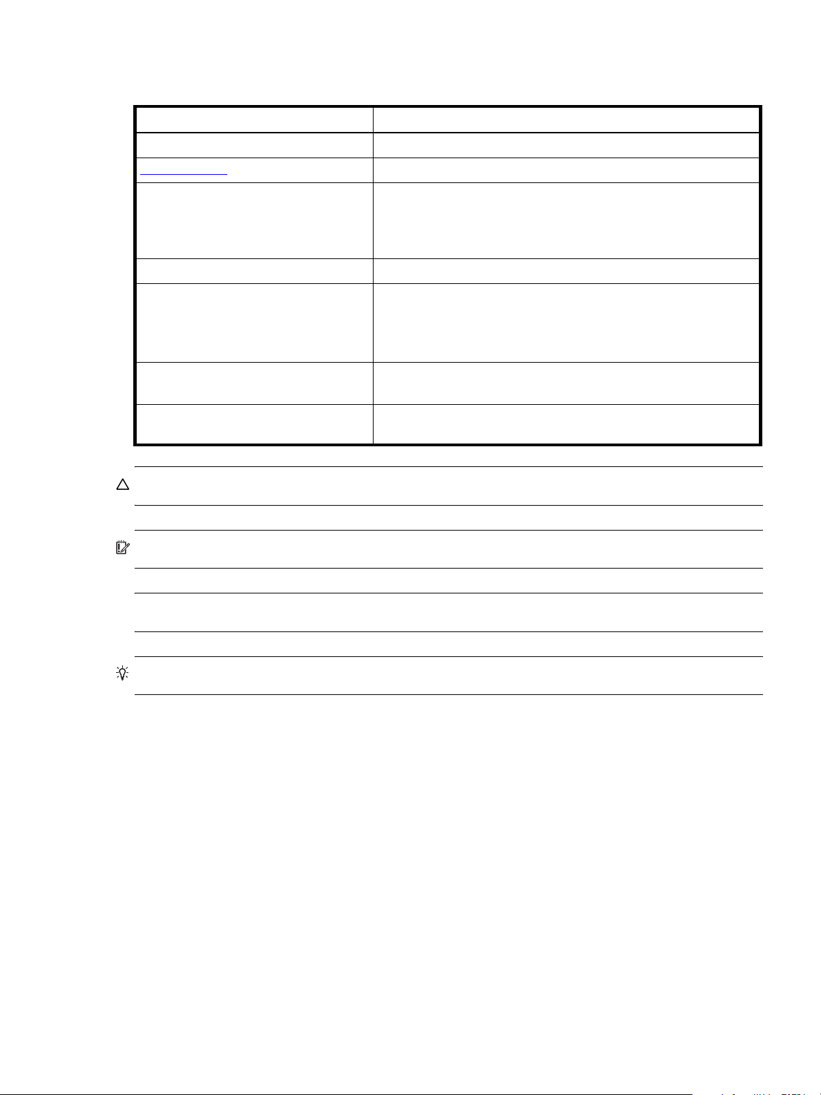
Document conventions and symbols
Table 2 Document conventions
Convention Element
Blue text Cross-reference links and e-mail addresses
Blue, underlined
Bold text • Key names
Italic text Text emphasis
Monospace text • File and directory names
Monospace, italic
Monospace, bold text Emphasis of file and directory names, system output, code, and text
text Web site addresses
• Text typed into a GUI element, such as into a box
• GUI elements that are clicked or selected, such as menu and list
items, buttons, and check boxes
• System output
• Code
• Text typed at the command-line
text • Code variables
• Command-line variables
typed at the command-line
CAUTION: Indicates that failure to follow directions could result in damage to equipment or data.
IMPORTANT: Provides clarifying information or specific instructions.
NOTE: Provides additional information.
TIP: Provides helpful hints and shortcuts.
AssuredSAN Ultra48 Series Setup Guide 13
Page 14

14 About this guide
Page 15
1Components
OK
2
3
4
5
Note: Remove this enclosure bezel to access the front panel components shown below
1, 2
1
Front panel components
AssuredSAN Ultra48 Series supports 2U48 enclosures. The 2U48 chassis—configured with up to 48 2.5"
small form factor (SFF) disks—is used as either a controller enclosure or expansion enclosure.
Supported expansion enclosures are used for adding storage. The 4144 is the high-capacity 2U48 drive
enclosure used for adding storage. The 4144 is briefly described in this guide.
Storage enclosures support dual I/O modules (IOMs), and they are equipped with two redundant AC
power supply modules.
48-drive enclosure front panel components
Enclosure bezel installed
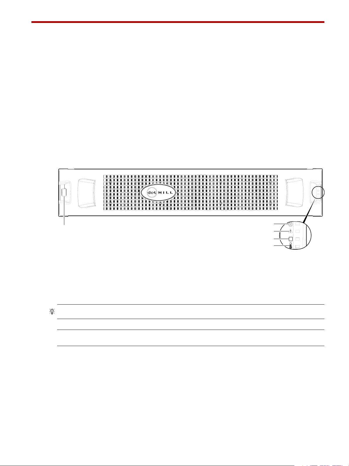
When the enclosure is in operation, the bezel should be installed on the front panel as shown in Figure 1.
The enclosure bezel is equipped with an EMI (Electromagnetic Interface) shield to provide protection for the
disks.
1 Enclosure ID LED
2 Enclosure status LED: Unit Locator
3 Enclosure status LED: Fault/Service Required
Figure 1 2U48 enclosure: front panel with bezel installed
TIP: See Enclosure bezel attachment and removal on page 71 and Figure 35 on page 72 (2U48).
NOTE: Front and rear panel LEDs for controller enclosures are described in LED descriptions.
4 Enclosure status LED: FRU OK
5 Enclosure status LED: Temperature Fault
AssuredSAN Ultra48 Series Setup Guide 15
Page 16
Enclosure bezel removed
1 20
61
7
2
Left ear
Right ear
Note: Integers atop drawers indicate drawer numbering sequence.
OK
(Silk screens on bezel)
14
3
5
8
Drawer Profiles
Disk bays with sequentially−numbered disk slots
Right side view
(Revolved Y −90°)
Left side view
(Revolved Y +90°)
47
46
45
44
43
42
41
40
39
38
37
36
35
34
33
32
31
30
29
28
27
26
25
24
23
22
21
20
19
18
17
16
0
1
15
14
13
12
11
10
9
8
7
6
5
4
3
2
1
0
Right side view
(Revolved Y −90°)
2
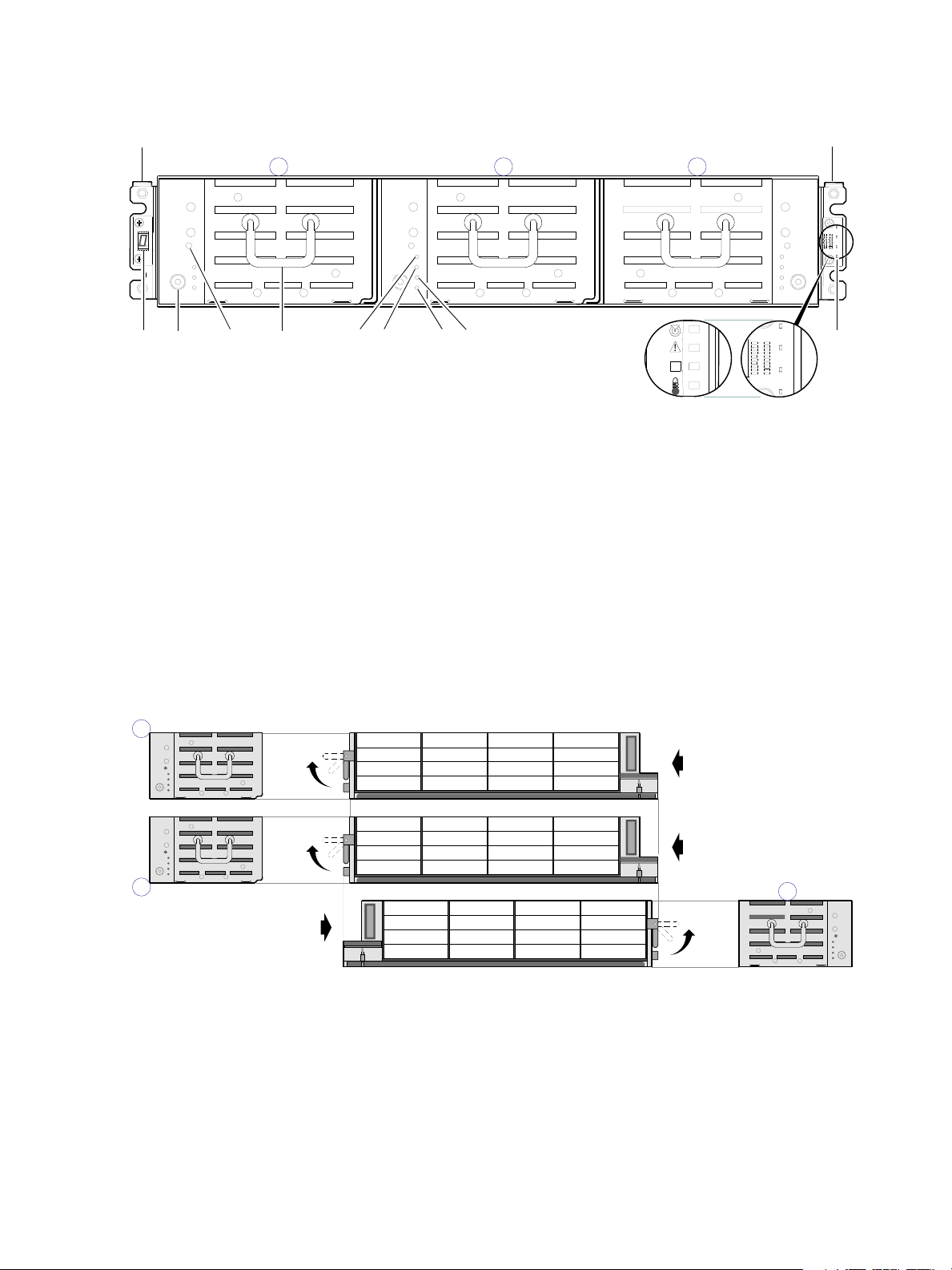
To access the drawers, you must remove the enclosure bezel (shown removed in Figure 2).
1 Enclosure ear LEDs (see Figure 1 on page 15)
2 Thumbscrew for securing or accessing drawer
3 Disabled button (used by engineering only)
4 Drawer handle (shown in stowed position)
Enclosure drawers
You can open the enclosure drawers to access the disks. Drawers 0 and 1 provide access to disk bays from
the right side of the drawer; whereas drawer 2 provides access to disk bays from the left side of the
drawer. These respective side views—or profiles—are shown below.
5 Drawer status LED: FRU OK
6 Drawer status LED: Fault/Service Required
7 Drawer status LED: OK to Remove
8 Drawer status LED: Unit Locator
Figure 2 2U48 enclosure: front panel with bezel removed
Figure 3 2U48 enclosure: drawer front and side views with disk slot numbering
Your 2U48 enclosure is shipped with the drawers installed, but they are not populated with disks.
Depending on the your product configuration, disk bay blanks—also known as Air Management Solution
(AMS) inserts—might be installed. Locate the box containing your sledded disks and AMS inserts (if
applicable) in preparation for populating the drive slots.
• See Table 3 on page 23 for sequential tasks required for successful enclosure installation.
• See Populating drawers on page 24 for instructions on installing disks and AMS inserts.
16 Components
Page 17
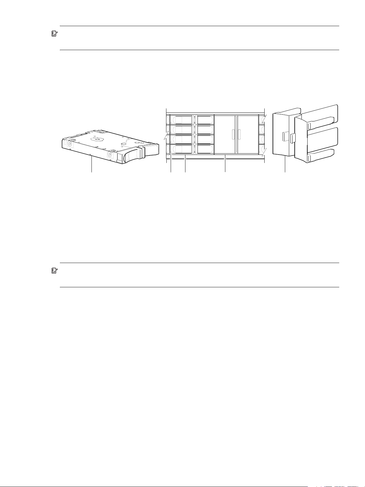
IMPORTANT: Disk drive slot numbering is also provided on the label that is laminated to the sheet metal
1 23 5
4
Disks and AMS installed in drive slots
(partial view of a 4-bay drawer)
housing (top face) on each drawer. Refer to the drawer label when installing disks into the drawer.
Figure 4 below provides a sample partial configuration of disk bays within a drawer. The bay on the left is
populated with four disks, whereas the adjacent bay on the right contains an AMS insert to manage air
flow within the enclosure to maintain optimal operating temperature.
1 2.5" sledded disk module assembly pictorial
2 Disk drive status LED (see Disk drive LED on page 75)
3 2.5" disk drive module (installed in 3 of 4 disk bays)
1
The disk is oriented in the sled such that its PCBA faces upward on the top side of the disk drive module as shown.
2
Electromagnetic interface protection for disk drives is provided by the EMI shield within the enclosure bezel.
3
The AMS insert spans an entire disk bay (4 slots). A single disk slot AMS might become a future option.
1, 2
Figure 4 2U48 enclosure: sample drawer population
IMPORTANT: Empty bays will cause overheating. To avoid overheating, install an AMS insert in disk bays
that do not contain quantity four disk drive modules.
Disk drives used in Ultra48 Series enclosures
Ultra48 Series enclosures support SFF Midline SAS, SFF Enterprise SAS, and SFF SSD disks. They also
support LFF/SFF Midline SAS and LFF/SFF Enterprise self-encrypting disks that work with the Full Disk
Encryption (FDE) feature. For information about creating vdisks and adding spares using different disk
drive types, see the AssuredSAN 4004 Series RAIDar User Guide or online help. Also see FDE
considerations on page 27.
4 Air Management Solution (AMS) insert (installed)
5 AMS insert pictorial
3
3
AssuredSAN Ultra48 Series Setup Guide 17
Page 18
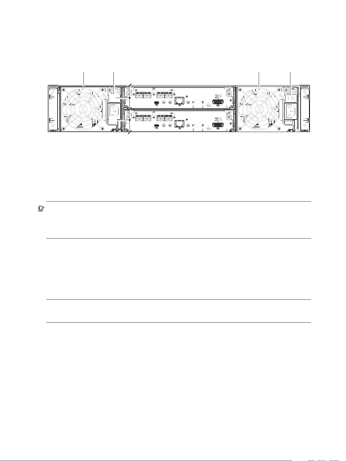
Controller enclosure — rear panel layout
CACHE
LINK
ACT
6Gb/s
CACHE
LINK
ACT
6Gb/s
CLI
CLI
PORT 2 PORT 3
SERVICE−1SERVICE−2
PORT 0 PORT 1
CLI
CLI
PORT 2 PORT 3
SERVICE−1SERVICE−2
PORT 0 PORT 1
1 1
4
2 2
3
The diagram and table below display and identify important component items that comprise the rear panel
layout of an AssuredSAN Ultra48 Series controller enclosure. The 4844 is shown as a representative
example of 2U48 controller enclosure models included in the product series.
1 AC power supply
2 AC power switch
3 Controller module A (see face plate detail figures)
4 Controller module B (see face plate detail figures)
Figure 5 Ultra48 Series high-capacity controller enclosure: rear panel
A controller enclosure accommodates two AC power supply FRUs within the two power supply slots (see
two instances of callout No.1 above). The controller enclosure accommodates two controller module FRUs
of the same type within the I/O module (IOM) slots (see callouts No.3 and No.4 above).
IMPORTANT: Ultra48 Series controller enclosures support dual-controller configuration only.
Single-controller support is provided only when a controller fails over to its partner controller. A controller
module must be installed in each IOM slot to ensure sufficient airflow through the enclosure during
operation.
The diagrams with tables that immediately follow provide descriptions for the controller modules and
power supply modules that can be installed into the rear panel of an Ultra48 Series controller enclosure.
Showing controller modules and power supply modules separately from the enclosure enables improved
clarity in identifying the component items called out in the diagrams and described in the tables.
Descriptions are also provided for optional drive enclosures supported by Ultra48 Series controller
enclosures for expanding storage capacity.
NOTE: Ultra48 Series enclosures support hot-plug replacement of redundant controller modules, fans,
power supplies, and expansion modules. Hot-add replacement of drive enclosures is also supported.
18 Components
Page 19
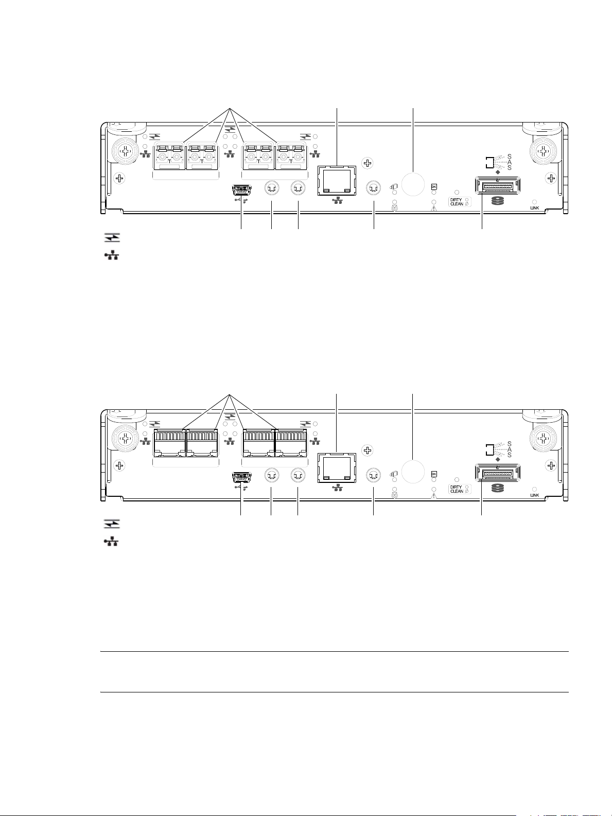
4844 controller module — rear panel components
CACHE
CLI
CLI
LINK
ACT
6Gb/s
SERVICE−1SERVICE−2
PORT 0 PORT 1 PORT 2 PORT 3
5
2 3 6 8
1
7
4
= FC LEDs
= 10GbE iSCSI LEDs
CACHE
CLI
CLI
LINK
ACT
6Gb/s
SERVICE−1SERVICE−2
PORT 0 PORT 1 PORT 2 PORT 3
5
2 3 6 8
1
7
4
= FC LEDs
= 1Gb iSCSI LEDs (all CNC ports use 1 Gb RJ-45 SFPs in this figure)
Figure 6 shows CNC ports configured with SFPs supporting either 4/8/16 Gb FC or 10GbE iSCSI. The
SFPs look identical. Refer to the CNC LEDs that apply to the specific configuration of your CNC ports.
1 CNC ports used for host connection or replication
(see Install an SFP transceiver on page 95)
2 CLI port (USB - Type B) [see Appendix D]
3 Service port 2 (used by service personnel only)
4 Reserved for future use
5 Network port
6 Service port 1 (used by service personnel only)
7 Disabled button (used by engineering only)
(Sticker shown covering the opening)
8 mini-SAS expansion port
Figure 6 4844 controller module face plate (FC or 10GbE iSCSI)
Figure 7 shows CNC ports configured with 1 Gb RJ-45 SFPs.
1 CNC ports used for host connection or replication
(see Install an SFP transceiver on page 95)
2 CLI port (USB - Type B) [see Appendix D]
3 Service port 2 (used by service personnel only)
4 Reserved for future use
5 Network port
6 Service port 1 (used by service personnel only)
7 Disabled button (used by engineering only)
(Sticker shown covering the opening)
8 mini-SAS expansion port
Figure 7 4844 controller module face plate (1 Gb RJ-45)
NOTE: See CNC ports used for host connection on page 11 for more information about CNC technology. For
CNC port configuration, see the “Configuring host ports” topic within the RAIDar User Guide or online help.
AssuredSAN Ultra48 Series Setup Guide 19
Page 20
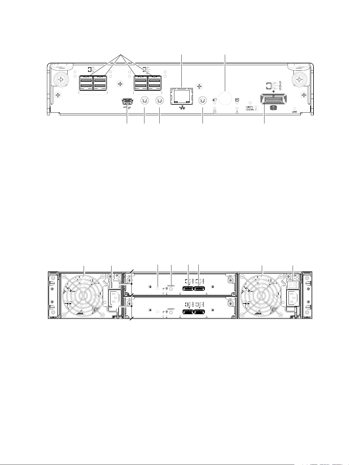
4544 controller module — rear panel components
CACHE
CLI
CLI
LINK
ACT
6Gb/s
SERVICE−1SERVICE−2
ACT
LINK
12Gb/s
S
S
A
ACT
LINK
SAS 0 SAS 1
ACT
LINK
12Gb/s
S
S
A
ACT
LINK
SAS 2 SAS 3
5
2 3 6 8
1
7
4
IN OUT
IN OUT
6Gb/s 6Gb/s
6Gb/s 6Gb/s
1
6
7 85
1
4
2
2
3
Figure 8 shows host ports configured with 12 Gbit/s HD mini-SAS (SFF-8644) connectors.
1 HD mini-SAS ports used for host connection
2 CLI port (USB - Type B) [see Appendix D]
3 Service port 2 (used by service personnel only)
4 Reserved for future use
6 Service port 1 (used by service personnel only)
7 Disabled button (used by engineering only)
(Sticker shown covering the opening)
8 mini-SAS expansion port
5 Network port
Figure 8 4544 controller module face plate (HD mini-SAS)
4144 drive enclosure rear panel components
AssuredSAN Ultra48 Series controller enclosures support the high-capacity 2U48 drive enclosure for
adding storage. The 4144 expansion enclosure uses the same 2.5" SFF disk drive modules use by the
Ultra48 Series controller enclosures (see Figure 4 on page 17 for a visual representation of disk drive
modules and AMS inserts used by the 4144). The 4144 uses mini-SAS (SFF-8088) connectors to facilitate
back-end SAS expansion. See Cable requirements for storage enclosures on page 29 for cabling
information.
1 AC Power supply
2 AC Power supply switch
3 Expansion module A
4 Expansion module B
Figure 9 4144 high-capacity expansion enclosure: rear panel
Component installation and replacement
Installation and replacement of Ultra48 Series FRUs (field-replaceable units) is addressed in the
AssuredSAN Ultra48 Series FRU Installation and Replacement Guide within the “Procedures” chapter.
FRU procedures facilitate replacement of a damaged chassis or chassis component:
• Replacing a controller or expansion module
• Replacing a disk drive module
20 Components
5 Disabled button (used by engineering/test only)
6 Service port (used by service personnel only)
7 SAS In port
8 SAS Out port
Page 21

• Replacing a power supply unit with integrated cooling fans.
• Replacing ear components
• Replacing a Fibre Channel transceiver
• Replacing a 10GbE SFP+ transceiver
• Replacing a 1 Gb SFP transceiver
• Replacing a controller enclosure chassis
See Dot Hill’s Customer Resource Center web site for additional information: http://crc.dothill.com
Select AssuredSAN & R/Evolution Products > Ultra48 Series to download the FRU I&R guide.
Cache
To enable faster data access from disk storage, the following types of caching are performed:
• Write-back or write-through caching. The controller writes user data into the cache memory in the
controller module rather than directly to the disks. Later, when the storage system is either idle or aging
—and continuing to receive new I/O data—the controller writes the data to the disks.
• Read-ahead caching. The controller detects sequential data access, reads ahead into the next
sequence of data—based upon settings—and stores the data in the read-ahead cache. Then, if the
next read access is for cached data, the controller immediately loads the data into the system memory,
avoiding the latency of a disk access.
TIP: See the “About volume cache options” and “Changing system cache settings” topics in the RAIDar
User Guide for setting options.
CompactFlash
During a power loss or controller failure, data stored in cache is saved off to non-volatile memory
(CompactFlash). The data is restored to cache, and then written to disk after the issue is corrected. To
protect against writing incomplete data to disk, the image stored on the CompactFlash is verified before
committing to disk.
.
The CompactFlash card is located at the midplane-facing end of the controller module as shown in
Figure 10 on page 22. Do not remove the card; it is used for cache recovery only.
IMPORTANT: Customer removal of CompactFlash will void the product warranty.
IMPORTANT: In dual-controller configurations featuring one healthy partner controller, there is no need to
transport failed controller cache to a replacement controller because the cache is duplicated between the
controllers (subject to volume write optimization setting).
IMPORTANT: The Ultra48 Series enclosures support dual-controller environments only. Do not transport
the CompactFlash since data corruption might occur. Single-controller support is provided only when a
controller fails over to its partner controller.
AssuredSAN Ultra48 Series Setup Guide 21
Page 22
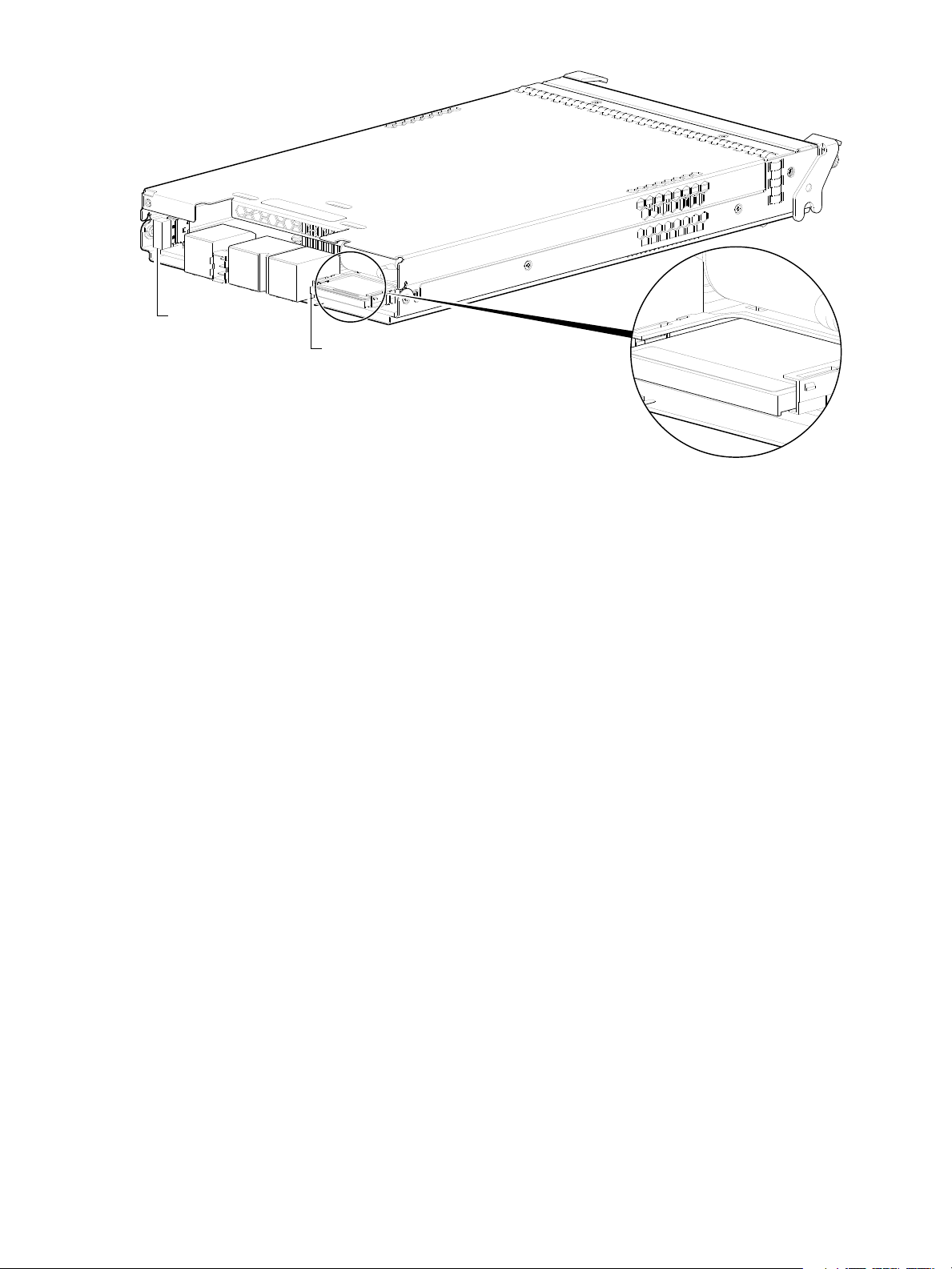
Supercapacitor pack
Do not remove
Used for cache recovery only
Controller module pictorial
CompactFlash card
(Midplane-facing rear view)
Host interface
USB - Type A
(shown covered)
To protect controller module cache in case of power failure, each controller enclosure model is equipped
with supercapacitor technology, in conjunction with CompactFlash memory, built into each controller
module to provide extended cache memory backup time. The supercapacitor pack provides energy for
backing up unwritten data in the write cache to the CompactFlash, in the event of a power failure.
Unwritten data in CompactFlash memory is automatically committed to disk media when power is restored.
In the event of power failure, while cache is maintained by the supercapacitor pack, the Cache Status LED
flashes at a rate of 1/10 second on and 9/10 second off.
Figure 10 CompactFlash card
22 Components
Page 23
2Installing the enclosures
Installation checklist
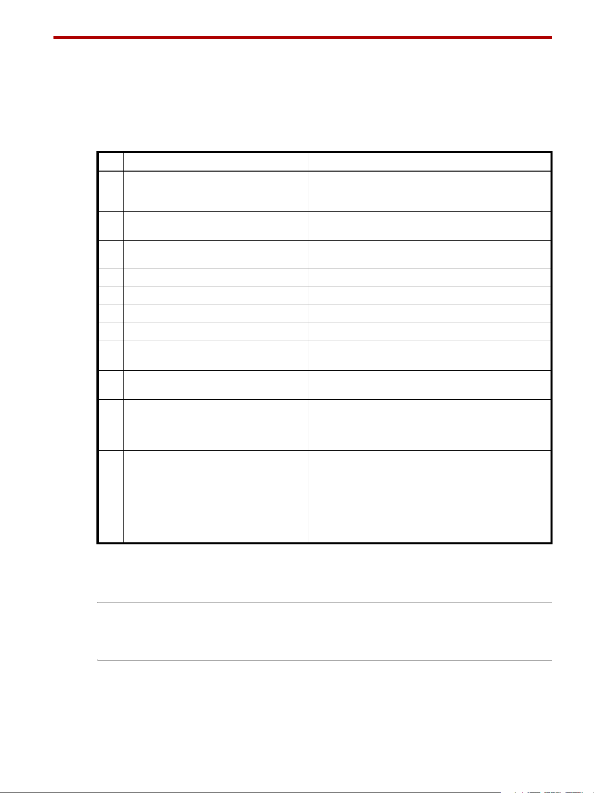
The following table outlines the steps required to install the enclosures, and initially configure and provision
the storage system. To ensure successful installation, perform the tasks in the order presented.
Table 3 Installation checklist
Step Task Where to find procedure
1. Install the controller enclosure and optional
drive enclosures in the rack, and attach the
enclosure bezel.
2. Install the disk drive modules and any air
management solution inserts into the drawers.
3. Connect controller enclosure and optional
drive enclosures.
4. Connect power cords. See Powering on/powering off on page 31.
5. Test enclosure connectivity. See Testing enclosure connections on page 31.
6. Install required host software. See Host system requirements on page 33.
7. Connect hosts.
8. Connect remote management hosts.
9. Obtain IP values and set network port IP
properties on the controller enclosure.
10. Use the CLI to set the host interface protocol. See CNC technology on page 33. The 4844 models allow
11 . Perform initial configuration tasks
• Sign-in to the web-browser interface
(RAIDar) to access the application GUI.
• Verify firmware revisions and update if
necessary.
• Initially configure and provision the system
using RAIDar.
1
2
2
3
:
See the rack-mount bracket kit installation instructions
pertaining to your enclosure. Also refer to the bezel
attachment instructions for your enclosure.
See Populating drawers on page 24.
(Remove the bezel for this step. Re-attach when finished.)
See Connecting the controller enclosure and drive enclosures
on page 28.
See Connecting the enclosure to hosts on page 33.
See Connecting a management host on the network,
page 40.
See Obtaining IP values on page 45.
For USB CLI port and cable use, see Appendix D.
you to set the host interface protocol for your qualified SFP
option. Use the set host-port-mode command as
described in the CLI Reference Guide or online help.
Topics below correspond to bullets at left:
See “Getting Started” in the web-posted AssuredSAN 4004
Series RAIDar User Guide.
See Updating firmware on page 45. Also see the same topic
in the AssuredSAN 4004 Series RAIDar User Guide.
See “Configuring the System” and “Provisioning the System”
topics in the RAIDar User Guide or online help.
1
See the AssuredSAN Ultra48 Series FRU Installation and Replacement Guide for illustrations and narrative describing attachment of
enclosure bezels to 2U48 chassis. See also Enclosure bezel attachment and removal on page 71.
2
For more about hosts, see the “About hosts” topic in the AssuredSAN 4004 Series RAIDar User Guide.
3
RAIDar is introduced in Accessing RAIDar on page 51. See the RAIDar User Guide or online help for additional information.
NOTE: Additional installation notes:
• Controller modules within the same enclosure must be of the same type.
• For optimal performance, do not mix 6 Gb and 3 Gb disk drives within the same enclosure.
AssuredSAN Ultra48 Series Setup Guide 23
Page 24
Populating drawers
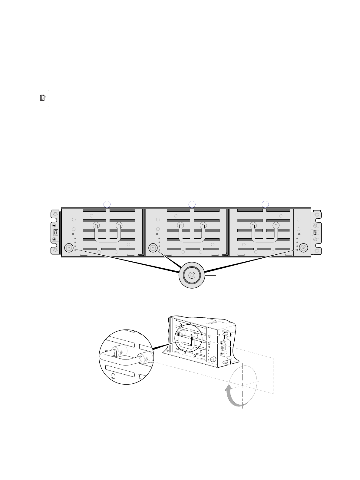
1 20
Enclosure front panel with bezel removed showing left (0), middle, (1) and right (2) drawers
Loosen screw on target drawer
90°
The drawer handle functions identically on all drawers.
Pull position
Although the 2U48 chassis provides pre-assembled and pre-installed drawer FRUs (drawers), disk drive
modules must be installed into the drawers. In addition to locating your disk modules—and any Air
Management Solution (AMS) inserts, you should become familiar with the following concepts before
populating the drawers:
• Full Disk Encryption (FDE) firmware feature (see FDE considerations on page 27).
• Preventing electrostatic discharge (see Electrostatic discharge appendix).
IMPORTANT: Please review the bullet topics above before populating the drawers.
Opening and closing a drawer
You can open a drawer for visual inspection of disk bays. Before accessing the drawer via its handle, you
must first remove the enclosure bezel (see Enclosure bezel removal on page 71). Given that the enclosure
bezel is required to provide EMI protection for disks, you should re-attach the bezel to the enclosure after
examining the drawer (see Enclosure bezel attachment on page 71).
1. Using a Torx T10 screwdriver, loosen the drawer stop screw on the front face of the drawer.
Once the screw is loosened, turn the outer thumbwheel counter-clockwise to unlock the drawer. Take
care not to remove the screw.
Figure 11 Opening a drawer: loosen the drawer stop screw
2. Revolve the drawer handle upwards by 90° to enable pulling the drawer outward for viewing disks.
3. Face the front of the drawer—and using the handle—pull the drawer outward along the drawer slide
until it meets the drawer stop.
24 Installing the enclosures
Figure 12 Opening a drawer: revolve the handle
Page 25
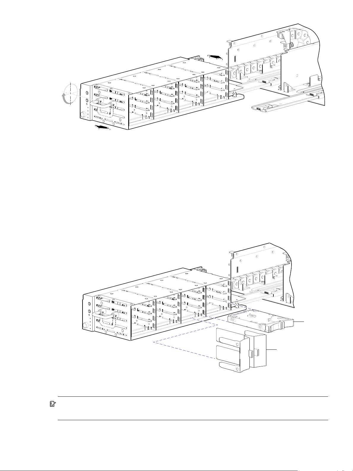
Figure 13 Opening and closing a drawer: pull or push drawer along slide
90°
Disk
AMS
To close the drawer, simply slide the drawer into the enclosure along the drawer slide until it properly seats
in the drawer bay. Take care to ensure there are no loose cable wires protruding beyond the limits of the
igus chainflex cable. After closing the drawer, revolve the handle downwards such that it is flush with the
drawer front panel—in its stowed position—and re-attach the bezel to the front of the enclosure.
Aligning an AMS or disk module for installation into a drawer
Once you have opened the drawer, you can access the disk bays. The enclosure uses an SFF sledded disk
positioned to lay on its side—with the disk PCBA facing up—for insertion into the disk slot within the
drawer. Each disk is mated to a connector on the drawer PCBA. In the absence of quantity-four disks, the
enclosure uses an AMS insert within disk bays to manage air flow within the enclosure, to help maintain
optimal operating temperature.
Figure 14 Align AMS or disk module for installation into the drawer
IMPORTANT: Each disk bay must be populated with either an AMS insert or a full complement of four
disk drive modules.
AssuredSAN Ultra48 Series Setup Guide 25
Page 26
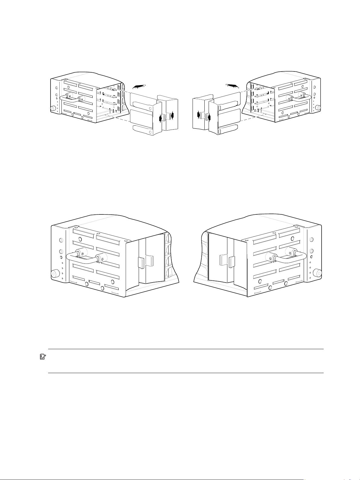
Installing an AMS
Align AMS for insertion into disk bay
Right drawerLeft or middle drawer
Right drawerLeft or middle drawer
Refer to Figure 15 when orienting the AMS for insertion into the target drawer. If you are installing into the
left drawer or middle drawer, refer to the illustration on the left when performing this step-procedure. If you
are installing into the right drawer, refer to the illustration on the right when performing this step-procedure.
1. Squeeze the latch release flanges together—so that the locking-nib will clear the sheet metal bay
wall—and insert the AMS into the target disk bay.
2. Verify that the AMS is firmly seated in place.
The installed disk drive module should now appear as shown in the sectioned cutaway views of the
respective drawers in Figure 16.
Figure 15 Orient the AMS for installation
Installing a disk module
IMPORTANT: Please review FDE considerations on page 27 before populating the Ultra48 Series
enclosure drawers.
Refer to Figure 17 when orienting the disk drive module for insertion into the target drawer. If you are
installing a disk drive module in the left drawer or middle drawer, refer to the illustration on the left when
performing the step-procedure. If you are installing a disk drive module in the right drawer, refer to the
illustration on the right when performing this step-procedure.
26 Installing the enclosures
Figure 16 Secure the AMS into the disk bay
Page 27
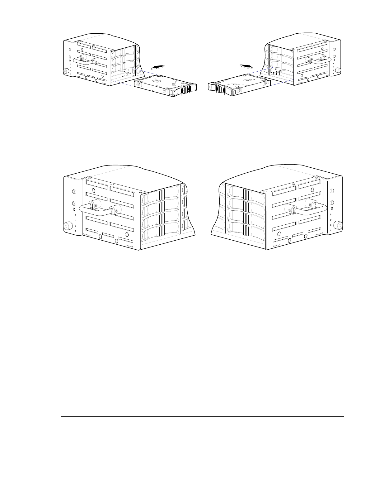
Figure 17 Orient the disk for installation
Align SFF 2.5" disk module for insertion into drive slot
Left or middle drawer Right drawer
Left or middle drawer Right drawer
1. While supporting the bottom of the disk module with one hand (disk PCBA should be facing up and
latch release flanges should be facing out)—align the disk for insertion into the target disk slot.
2. Using your other hand, squeeze the latch release flanges together—so that the locking-nib will clear the
sheet metal bay wall—and insert the disk drive module into the target slot.
Figure 18 Secure the disk module into the drive slot
3. Gently push the disk drive module into the slot until it latches in place.
The installed disk drive module should now appear as shown in the sectioned cutaway views of the
respective drawers in Figure 18.
For a more complete discussion—including disk removal and replacement— see the “Replacing a disk
drive module” topic within the AssuredSAN Ultra48 Series FRU Installation and Replacement Guide.
FDE considerations
The Full Disk Encryption feature available via the management interfaces requires use of self-encrypting
drives (SED) which are also referred to as FDE-capable disk drive modules. When installing FDE-capable
disk drive modules, follow the same procedures for installing disks that do not support FDE. The exception
occurs when you move FDE-capable disk drive modules for one or more vdisks to a different system, which
requires additional steps.
The procedures for using the FDE feature, such as securing the system, viewing disk FDE status, and
clearing and importing keys are performed using RAIDar or CLI commands (see the 4004 Series version of
the RAIDar User Guide guide or CLI Reference Guide for more information).
NOTE: When moving FDE-capable disk drive modules for a vdisk, stop I/O to any volumes in the vdisk
before removing the disk drive modules. Follow the “Removing a disk drive module” and “Installing a disk
drive module” procedures within the AssuredSAN Ultra48 Series FRU Installation and Replacement Guide.
Import the keys for the disks so that the disk content becomes available.
AssuredSAN Ultra48 Series Setup Guide 27
Page 28

While replacing or installing FDE-capable disk drive modules, consider the following:
• If you are installing FDE-capable disk drive modules that do not have keys into a secure system, the
system will automatically secure the disks after installation. Your system will associate its existing key
with the disks, and you can transparently use the newly-secured disks.
• If the FDE-capable disk drive modules originate from another secure system, and contain that system’s
key, the new disks will have the Secure, Locked status. The data will be unavailable until you enter the
passphrase for the other system to import its key. Your system will then recognize the metadata of the
vdisks and incorporate it. The disks will have the status of Secure, Unlocked and their contents will be
available:
• To view the FDE status of disks, use RAIDar or the show fde-state CLI command.
• To import a key and incorporate the foreign disks, use RAIDar or the set fde-import-key CLI
command.
NOTE: If the FDE-capable disks contain multiple keys, you will need to perform the key importing
process for each key to make the content associated with each key become available.
• If you do not want to retain the disks’ data, you can repurpose the disks. Repurposing disks deletes all
disk data, including lock keys, and associates the current system’s lock key with the disks.
To repurpose disks, use RAIDar or the
• You need not secure your system to use FDE-capable disks. If you install all FDE-capable disks into a
system that is not secure, they will function exactly like disks that do not support FDE. As such, the data
they contain will not be encrypted. If you decide later that you want to secure the system, all of the disks
must be FDE-capable.
• If you install a disk module that does not support FDE into a secure system, the disk will have the
Unusable status and will be unavailable for use.
• If you are re-installing your FDE-capable disk drive modules as part of the process to replace the
chassis-and-midplane FRU, you must insert the original disks and re-enter their FDE passprhase (see the
AssuredSAN Ultra48 Series FRU Installation and Replacement Guide for more information).
set disk CLI command.
Connecting the controller enclosure and drive enclosures
AssuredSAN Ultra48 Series controller enclosures—available in 48-drive (2.5") 2U chassis—support up to
four enclosures (including the controller enclosure), or a maximum of 192 disk drives. The Ultra48 Series
enclosures support both straight-through and reverse SAS cabling. Reverse cabling allows any drive
enclosure to fail—or be removed—while maintaining access to other enclosures. Fault tolerance and
performance requirements determine whether to optimize the configuration for high availability or high
performance when cabling. AssuredSAN Ultra48 Series controller modules support both 3-Gbps and
6-Gbps internal disk drive speeds together with 3-Gbps and 6-Gbps expander link speeds.
CAUTION: Some 6-Gbps disks might not consistently support a 6-Gbps transfer rate. If this happens, the
system automatically adjusts transfers to those disks to 3 Gbps, increasing reliability and reducing error
messages with little impact on system performance. This rate adjustment persists until the controller is
restarted or power-cycled.
Cabling diagrams in this section show fault-tolerant cabling patterns. Controller and expansion modules
are identified by <enclosure-ID><controller-ID>. When connecting multiple drive enclosures, use
reverse cabling to ensure the highest level of fault tolerance, enabling controllers to access remaining drive
enclosures if a drive enclosure fails.
For example, the illustration on the left in Figure 20 on page 30 shows reverse cabling, wherein
controller 0A (i.e., enclosure-ID = 0; controller-ID = Able) is connected to expansion module 1A, with a
chain of connections cascading down (blue). Controller 0B is connected to the lower expansion
module (B) of the last drive enclosure in the chain, with connections moving in the opposite direction
(green). Several cabling examples are provided on the following pages.
28 Installing the enclosures
Page 29

Connecting the Ultra48 Series controller to the 4144 drive enclosure
The high capacity 4144 48-drive enclosure, supporting 6 Gb internal disk drive and expander link speeds,
can be attached to a Ultra48 Series controller enclosure using supported mini-SAS to mini-SAS cables of
0.5 m (1.64') to 2 m (6.56') length (see Figure 19 on page 30).
Cable requirements for storage enclosures
The Ultra48 Series enclosures support 6-Gbps or 3-Gbps expansion port data rates. Use only AssuredSAN
or OEM-qualified cables, and observe the following guidelines:
• When installing SAS cables to expansion modules, use only supported mini-SAS x4 cables with
SFF-8088 connectors supporting your 6 Gb application.
• Qualified mini-SAS to mini-SAS 0.5 m (1.64') cables are used to connect cascaded enclosures in the
rack. The “mini-SAS to mini-SAS” cable designator connotes SFF-8088 to SFF-8088 connectors.
• The maximum expansion cable length allowed in any configuration is 2 m (6.56').
• Cables required, if not included, must be separately purchased.
• When adding more than two drive enclosures, you may need to purchase additional 1 m or 2 m
cables, depending upon number of enclosures and cabling method used:
Spanning 3 drive enclosures requires 1 m (3.28') cables.
• You may need to order additional or longer cables when reverse-cabling a fault-tolerant configuration
(see Figure 20 on page 30).
• Use only AssuredSAN or OEM-qualified cables for host connection:
• Qualified Fibre Channel SFP and cable options
• Qualified 10GbE iSCSI SFP and cable options
• Qualified 1 Gb RJ-45 SFP and cable options
• Qualified HD mini-SAS cable options supporting SFF-8644 and SFF-8088 host connection
A qualified SFF-8644 to SFF-8644 cable option is used for connecting to a 12 Gbit/s enabled host;
whereas a qualified SFF-8644 to SFF-8088 cable option is used for connecting to a 6 Gbit/s
enabled host.
Summary of drive enclosure cabling illustrations
The following illustrations show both reverse and straight-through cabling examples featuring Ultra48
Series controller enclosures and compatible 4144 drive enclosures. All storage enclosures use mini-SAS
connectors for expansion.
NOTE: The Ultra48 Series controller enclosures and compatible drive enclosures support mini-SAS
SFF-8088 connectors for adding storage.
NOTE: For clarity, the schematic diagrams show only relevant details such as face plate outlines and
expansion ports. For detailed illustrations, see Controller enclosure — rear panel layout on page 18. Also
see the controller module face plate illustrations that follow the rear panel layout.
AssuredSAN Ultra48 Series Setup Guide 29
Page 30
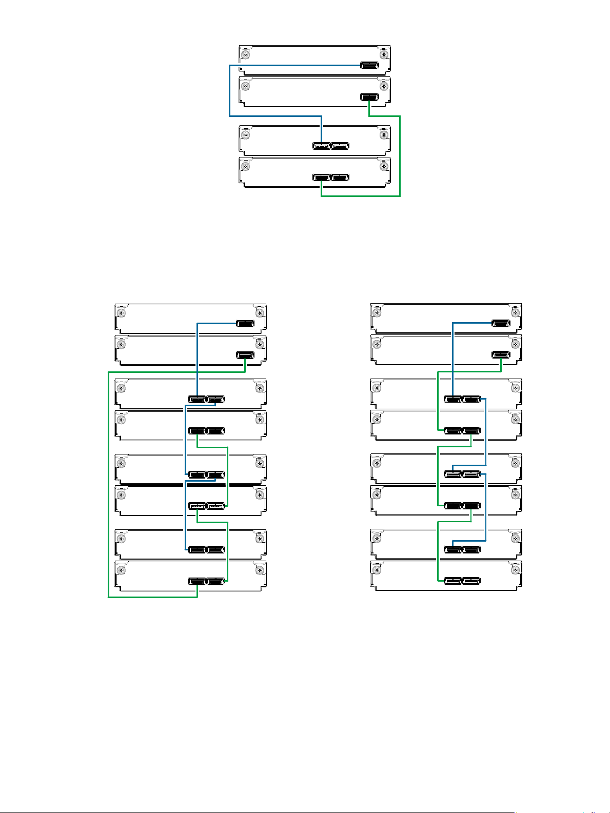
Figure 19 Cabling connections between a controller enclosure and one drive enclosure
Controller
enclosure
0
Drive
enclosure
In Out
In Out
0B
0A
1A
1B
Controller A
Controller B
1
Controller
enclosure
0
Drive
enclosure
In
Out
In Out
0B
0A
1A
1B
Controller A
Controller B
1
0B
0A
1A
1B
In Out
In
Out
In Out
In Out
Reverse cabling
Drive
enclosure
2
Drive
enclosure
3
Out
In
In Out
Out
In
Out
In
In Out
In Out
2B
2A
3A
3B
Straight-through cabling
2B
2A
3A
3B
Controller A
Controller B
The figure above provides an example of an Ultra48 Series controller enclosure cabled to a single drive
enclosure. The illustration shows cabling of enclosures equipped with dual IOMs.
See the “Replacing a controller or expansion module” topic within the AssuredSAN Ultra48 Series FRU
Installation and Replacement Guide for additional information.
The diagram at left (above) shows reverse cabling of an Ultra48 Series dual-controller enclosure and 4144
drive enclosures configured with dual-expansion modules. Controller module 0A is connected to expansion
module 1A, with a chain of connections cascading down (blue). Controller module 0B is connected to the
lower expansion module (3B), of the last expansion enclosure, with connections moving in the opposite
direction (green). Reverse cabling allows any expansion enclosure to fail—or be removed—while
maintaining access to other enclosures.
The diagram at right (above) shows the same storage components connected using straight-through
cabling. Using this method, if an expansion enclosure fails, the enclosures that follow the failed enclosure
30 Installing the enclosures
in the chain are no longer accessible until the failed enclosure is repaired or replaced.
Figure 20 Fault-tolerant cabling between a dual-controller enclosure and three drive enclosures
Page 31
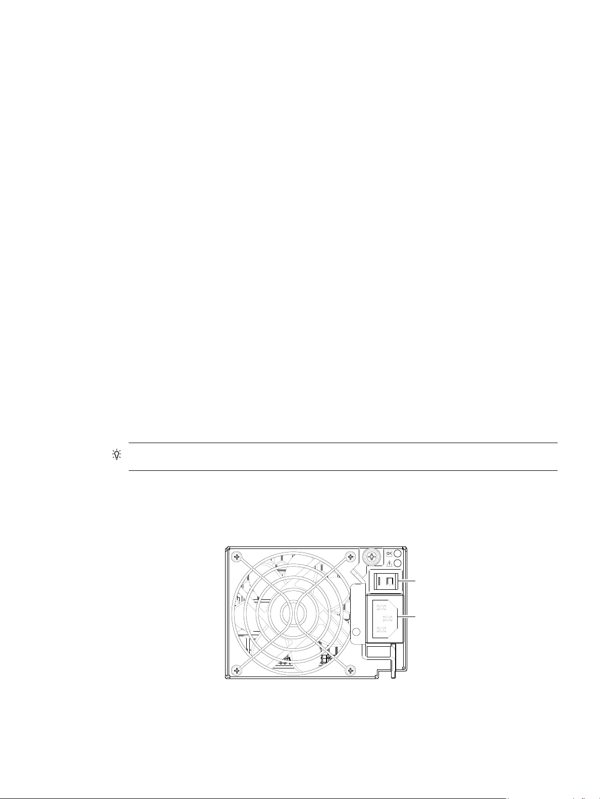
Refer to these diagrams when cabling multiple compatible drive enclosures together with the Ultra48 Series
Power
switch
Power
cord
connect
controller enclosure.
Testing enclosure connections
Power cycling procedures vary according to the type of power supply unit (PSU) provided with the
enclosure. Some compatible enclosure models are equipped with PSUs that do not have power switches;
whereas Ultra48 Series enclosures use a PSU model that is equipped with a power switch.
The following section, Powering on/powering off, describes power cycling procedures relative to PSUs
installed within enclosures. Once the power-on sequence succeeds, the storage system is ready to be
connected to hosts as described in Connecting the enclosure to hosts
Powering on/powering off
Before powering on the enclosure for the first time:
• Install all disk drive modules in the enclosure drawers so the controller can identify and configure them
at power-up.
• Connect the cables and power cords to the enclosure as described herein.
• Generally, when powering up, make sure to power up the enclosures and associated data host in the
following order:
•Drive enclosures first
This ensures that the disks in the drive enclosure have enough time to completely spin up before
being scanned by the controller modules within the controller enclosure.
While enclosures power up, their LEDs blink. After the LEDs stop blinking—if no LEDs on the front
and back of the enclosure are amber—the power-on sequence is complete, and no faults have been
detected. See LED descriptions on page 71 for descriptions of LED behavior.
• Controller enclosure next
Depending upon the number and type of disks in the system, it may take several minutes for the
system to become ready.
• Data host last (if powered down for maintenance purposes).
on page 33.
AC PSUs
AC power supplies are equipped with a power switch. The illustration below shows the face of an AC
power supply module as it appears when viewing the rear panel of the enclosure.
TIP: Generally, when powering off, you will reverse the order of steps used for powering on.
Figure 21 AC PSU with power switch
AssuredSAN Ultra48 Series Setup Guide 31
Page 32
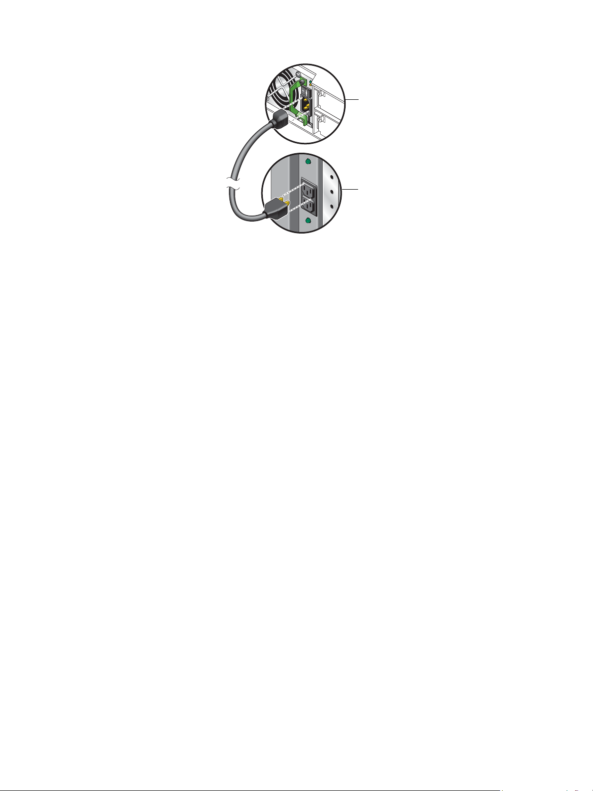
Connect power cord to AC power supply
Power supply
module
Rack power
source
Obtain two suitable AC power cords: one for each AC power supply that will connect to a separate power
source. See Figure 22 on page 32 and the illustration at left in Figure 21 when performing the following
steps:
1. Verify that the enclosure’s power switches are in the Off position.
2. Identify the power cord connector on the PSU, and locate the target power source.
3. Using the AC power cords provided, plug one end of the cord into the power cord connector on the
PSU. Plug the other end of the power cord into the rack power source.
4. Verify connection of primary power cords from the rack to separate external power sources.
See Power cycle.
Figure 22 AC power cord
Power cycle
Once the system is successfully cabled, use the following procedures to power on and power off.
To power on the system:
1. Power up drive enclosure(s). Allow several seconds for disks to spin up.
2. Power up the controller enclosure next.
To power off the system:
1. Stop all I/O from hosts to the system (see Stopping I/O on page 55).
2. Shut down both controllers using either method described below:
3. Press the power switches at the back of the controller enclosure to the Off position.
4. Press the power switches at the back of each drive enclosure to the Off position.
Press the power switches at the back of each drive enclosure to the On position.
Press the power switches at the back of the controller enclosure to the On position.
• Use RAIDar to shut down both controllers, as described in the online help and AssuredSAN 4004
Series RAIDar User Guide.
Proceed to step 3.
• Use the command-line interface (CLI) to shut down both controllers, as described in the AssuredSAN
4004 Series CLI Reference Guide.
32 Installing the enclosures
Page 33

3 Connecting hosts
Host system requirements
Hosts connected to an AssuredSAN Ultra48 Series controller enclosure must meet the following
requirements:
• Depending on your system configuration, host operating systems may require that multipathing is
supported.
If fault tolerance is required, then multipathing software may be required. Host-based multipath
software should be used in any configuration where two logical paths between the host and any
storage volume may exist at the same time. This would include most configurations where there are
multiple connections to the host or multiple connections between a switch and the storage.
• Use native Microsoft MPIO DSM support with Windows Server 2008 and Windows Server 2013.
Use either the Server Manager or the command-line interface (mpclaim CLI tool) to perform the
installation.
See the following web sites for information about using native Microsoft MPIO DSM:
http://support.microsoft.com/gp/assistsupport
http://technet.microsoft.com (search the site for “multipath I/O overview”)
Cabling considerations
Common cabling configurations address hosts, controller enclosures, drive enclosures, and switches. Host
interface ports on Ultra48 Series controller enclosures can connect to respective hosts via direct-attach or
switch-attach. Cabling systems to enable use of the optional AssuredRemote™ feature—to replicate
volumes—is yet another important cabling consideration. See Connecting two storage systems to replicate
volumes on page 40. The 4844 models can be licensed to support replication; whereas the 4544 models
do not support the feature.
Connecting the enclosure to hosts
A host identifies an external port to which the storage system is attached. Cable connections vary
depending on configuration. This section describes host interface protocols supported by Ultra48 Series
controller enclosures, while showing a few common cabling configurations.
NOTE: Ultra48 Series controllers use Unified LUN Presentation (ULP): a controller feature enabling a host
to access mapped volumes through any controller host port.
ULP can show all LUNs through all host ports on both controllers, and the interconnect information is
managed by the controller firmware. ULP appears to the host as an active-active storage system, allowing
the host to select any available path to access the LUN, regardless of vdisk ownership.
TIP: See “Configuring the system > Using the Configuration Wizard” in the AssuredSAN 4004 Series
RAIDar User Guide to initially configure the system or change system configuration settings (e.g.,
Configuring host ports).
CNC technology
AssuredSAN 4844 models use Converged Network Controller technology, allowing you to select the
desired host interface protocol(s) from the available FC or iSCSI host interface protocols supported by the
system. The small form-factor pluggable (SFP transceiver or SFP) connectors used in CNC ports are further
described in the subsections below. Also see CNC ports used for host connection on page 11 for more
information concerning use of CNC ports.
AssuredSAN Ultra48 Series Setup Guide 33
Page 34
NOTE: Controller modules are not shipped with pre-installed SFPs. Within your product kit, you will need
to locate the qualified SFP options, and install them into the CNC ports. See Install an SFP transceiver on
page 95.
IMPORTANT: Use the set host-port-mode CLI command to set the host interface protocol for CNC
ports using qualified SFP options. AssuredSAN 4844 models ship with CNC ports configured for FC.
When connecting CNC ports to iSCSI hosts, you must use the CLI (not RAIDar) to specify which ports will
use iSCSI. It is best to do this before inserting the iSCSI SFPs into the CNC ports (see Change the CNC
port mode on page 48 for instructions).
Fibre Channel protocol
AssuredSAN 4844 controller enclosures support two controller modules using the Fibre Channel interface
protocol for host connection. Each controller module provides four host ports designed for use with an FC
SFP supporting data rates up to 16 Gbit/s. When configured with FC SFPs, 4844 controller enclosures can
also be cabled to support the optionally-licensed AssuredRemote replication feature via the FC ports.
The controller supports Fibre Channel Arbitrated Loop (public or private) or point-to-point topologies. Loop
protocol can be used in a physical loop or in a direct connection between two devices. Point-to-point
protocol is used to connect to a fabric switch. See the set host-parameters command within the
AssuredSAN 4004 Series CLI Reference Guide for command syntax and details about parameter settings
relative to supported link speeds.
Fibre Channel ports are used in either of two capacities:
• To connect two storage systems through a Fibre Channel switch for use of AssuredRemote replication.
• For attachment to FC hosts directly, or through a switch used for the FC traffic.
The first usage option requires valid licensing for the AssuredRemote replication feature, whereas the
second option requires that the host computer supports FC and optionally, multipath I/O.
TIP: Use the RAIDar Configuration Wizard to set FC port speed. Within the RAIDar Reference Guide, see
“Configuring the system > Using the Configuration Wizard > Configuring host ports,” and scroll to FC port
options. Use the show host-parameters or show ports CLI commands to view information about
host ports.
10G b E iSCSI prot ocol
AssuredSAN 4844 controller enclosures support two controller modules using the Internet SCSI interface
protocol for host connection. Each controller module provides four host ports designed for use with a
10GbE iSCSI SFP supporting data rates up to 10 Gbit/s, using either one-way or mutual CHAP
(Challenge-Handshake Authentication Protocol).
TIP: See the “Configuring CHAP” topic in the RAIDar Reference Guide. Also see the important statement
about CHAP preceding the “Using the Replication Setup Wizard” procedure within that guide.
TIP: Use the RAIDar Configuration Wizard to set iSCSI port options. Within the RAIDar Reference Guide,
see “Configuring the system > Using the Configuration Wizard > Configuring host ports,” and scroll to
iSCSI port options. Use the show host-parameters or show ports CLI commands to view
information about host ports.
34 Connecting hosts
Page 35

The 10GbE iSCSI ports are used in either of two capacities:
• To connect two storage systems through a switch for use of AssuredRemote replication.
• For attachment to 10GbE iSCSI hosts directly, or through a switch used for the 10GbE iSCSI traffic.
The first usage option requires valid licensing for the AssuredRemote replication feature, whereas the
second option requires that the host computer supports Ethernet, iSCSI, and optionally, multipath I/O.
1 Gb iSCSI protocol
AssuredSAN 4844 controller enclosures support two controller modules using the Internet SCSI interface
protocol for host port connection. Each controller module provides four iSCSI host ports configured with an
RJ-45 SFP supporting data rates up to 1 Gbit/s, using either one-way or mutual CHAP.
TIP: See the “Configuring CHAP” topic in the RAIDar Reference Guide. Also see the admonition about
CHAP preceding the “Using the Replication Setup Wizard” procedure within that guide.
TIP: Use the RAIDar Configuration Wizard to set iSCSI port options. Within the RAIDar Reference Guide,
see “Configuring the system > Using the Configuration Wizard > Configuring host ports,” and scroll to
iSCSI port options. Use the show host-parameters or show ports CLI commands to view
information about host ports.
The 1 Gb iSCSI ports are used in either of two capacities:
• To connect two storage systems through a switch for use of AssuredRemote replication.
• For attachment to 1 Gb iSCSI hosts directly, or through a switch used for the 1 Gb iSCSI traffic.
The first usage option requires valid licensing for the AssuredRemote replication feature, whereas the
second option requires that the host computer supports Ethernet, iSCSI, and optionally, multipath I/O.
HD mini-SAS technology
AssuredSAN 4544 models use high-density mini-SAS (Serial Attached SCSI) interface protocol for host
connection.
12 Gb mini-SAS ports
Each controller module provides four SFF-8644 HD mini-SAS host ports supporting data rates up to 12
Gbit/s. HD mini-SAS host ports connect to hosts or switches; they are not used for replication. Use a
qualified SFF-8644 to SFF-8644 cable option when connecting to a 12 Gbit/s host. Use a qualified
SFF-8644 to SFF-8088 option when connecting to a supported 6 Gbit/s host.
Connecting direct attach configurations
AssuredSAN Ultra48 Series controller enclosures support up to eight direct-connect server connections,
four per controller module. Connect appropriate cables from the server’s HBAs to the controller module’s
host ports as described below, and shown in the following illustrations.
Fibre Channel host connection
To connect 4844 controller modules supporting (4/8/16 Gb) FC host interface ports to a server HBA or
switch—using the controller’s CNC ports—select a qualified FC SFP option.
Qualified options support cable lengths of 1 m (3.28'), 2 m (6.56'), 5 m (16.40'), 15 m (49.21'), 30 m
(98.43'), and 50 m (164.04') for OM4 multimode optical cables and OM3 multimode FC cables,
respectively. A 0.5 m (1.64') cable length is also supported for OM3. In addition to providing host
connection, these cables are used for connecting a local storage system to a remote storage system via a
switch, to facilitate use of the optional AssuredRemote replication feature.
AssuredSAN Ultra48 Series Setup Guide 35
Page 36

10GbE iSCSI host connection
To connect 4844 controller modules supporting 10GbE iSCSI host interface ports to a server HBA or
switch—using the controller’s CNC ports—select a qualified 10GbE SFP option.
Qualified options support cable lengths of 0.5 m (1.64'), 1 m (3.28'), 3 m (9.84'), 5 m (16.40'), and 7 m
(22.97') for copper cables; and cable lengths of 0.65 m (2.13'), 1 m (3.28'), 1.2 m (3.94'), 3 m (9.84'), 5
m (16.40'), and 7 m (22.97') for direct attach copper (DAC) cables. In addition to providing host
connection, these cables are used for connecting a local storage system to a remote storage system via a
switch, to facilitate use of the optional AssuredRemote replication feature.
1 Gb iSCSI host connection
To connect 4844 controller modules supporting 1Gb iSCSI host interface ports to a server HBA or
switch—using the controller’s CNC ports—select a qualified 1 Gb RJ-45 copper SFP option supporting
(CAT5-E minimum) Ethernet cables of the same lengths specified for 10GbE iSCSI above. In addition to
providing host connection, these cables are used for connecting a local storage system to a remote storage
system via a switch, to facilitate use of the optional AssuredRemote replication feature.
HD mini-SAS host connection
To connect 4544 controller modules supporting SAS host interface ports to a server HBA or switch —using
the controller’s SFF-8644 dual HD mini-SAS host ports—select a qualified HD mini-SAS cable option. A
qualified SFF-8644 to SFF-8644 cable option is used for connecting to a 12 Gbit/s enabled host; whereas
a qualified SFF-8644 to SFF-8088 cable option is used for connecting to a 6 Gbit/s host. Qualified
SFF-8644 to SFF-8644 options support cable lengths of 0.5 m (1.64'), 1 m (3.28'), 2 m (6.56'), and 4 m
(13.12'). Qualified SFF-8644 to SFF-8088 options support cable lengths of 1 m (3.28'), 2 m (6.56'), 3 m
(9.84'), and 4 m (13.12').
NOTE: Supported qualified cable options for host connection are subject to change.
NOTE: The diagrams that follow use a single representation for each CNC cabling example. This is due
to the fact that the CNC port locations and labeling are identical for each of the three possible
interchangeable SFPs supported by the system.
Within each cabling connection category, the HD mini-SAS model is shown beneath the CNC model.
Dual-controller configurations
A dual-controller configuration improves application availability because in the event of a controller failure,
the affected controller fails over to the partner controller with little interruption to data flow. A failed
controller can be replaced without the need to shut down the storage system.
In a dual-controller system, hosts use LUN-identifying information from both controllers to determine that up
to four paths are available to a given storage volume. Assuming MPIO software is installed, a host can use
any available data path to access a volume owned by either controller. The path providing the best
performance is through host ports on the volume’s owning controller. Both controllers share one set of
1,024 LUNs (0-1,023) for use in mapping volumes to hosts (see “ULP” in the AssuredSAN 4004 Series
RAIDar User Guide).
The illustrations below show dual-controller configurations for Ultra48 Series controller enclosures
equipped with either CNC ports or 12 Gb HD mini-SAS host ports.
IMPORTANT: Ultra48 Series controller enclosures support dual-controller configuration only.
Single-controller support is provided only when a controller fails over to its partner controller. A controller
module must be installed in each IOM slot to ensure sufficient airflow through the enclosure during
operation.
36 Connecting hosts
Page 37
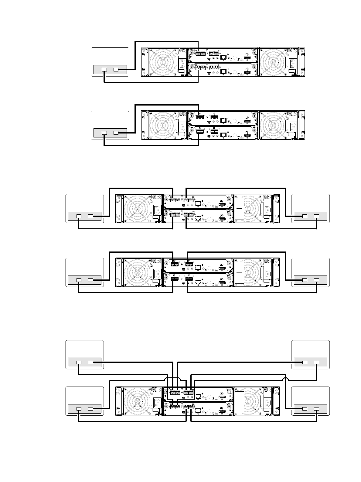
One server/one HBA/dual path
6Gb/s
6Gb/s
S
S
A
S
S
A
Server
4844
0A
0B
12Gb/s
S
S
A
6Gb/s
6Gb/s
S
S
A
S
S
A
12Gb/s
S
S
A
12Gb/s
S
S
A
12Gb/s
S
S
A
Server
4544
0A
0B
6Gb/s
6Gb/s
S
S
A
S
S
A
4844
Server 2
0A
0B
Server 1Server 1
12Gb/s
S
S
A
12Gb/s
S
S
A
6Gb/s
6Gb/s
S
S
A
S
S
A
12Gb/s
S
S
A
12Gb/s
S
S
A
4544
Server 2
0A
0B
Server 1Server 1
6Gb/s
S
S
A
6Gb/s
S
S
A
4844
Server 2
0A
0B
Server 1Server 1
Server 4Server 3
Figure 23 Connecting hosts: direct attach—one server/one HBA/dual path
Two servers/one HBA per server/dual path
Figure 24 Connecting hosts: direct attach—two servers/one HBA per server/dual path
Four servers/one HBA per server/dual path
Figure 25 Connecting hosts: direct attach—four servers/one HBA per server/dual path
AssuredSAN Ultra48 Series Setup Guide 37
Page 38
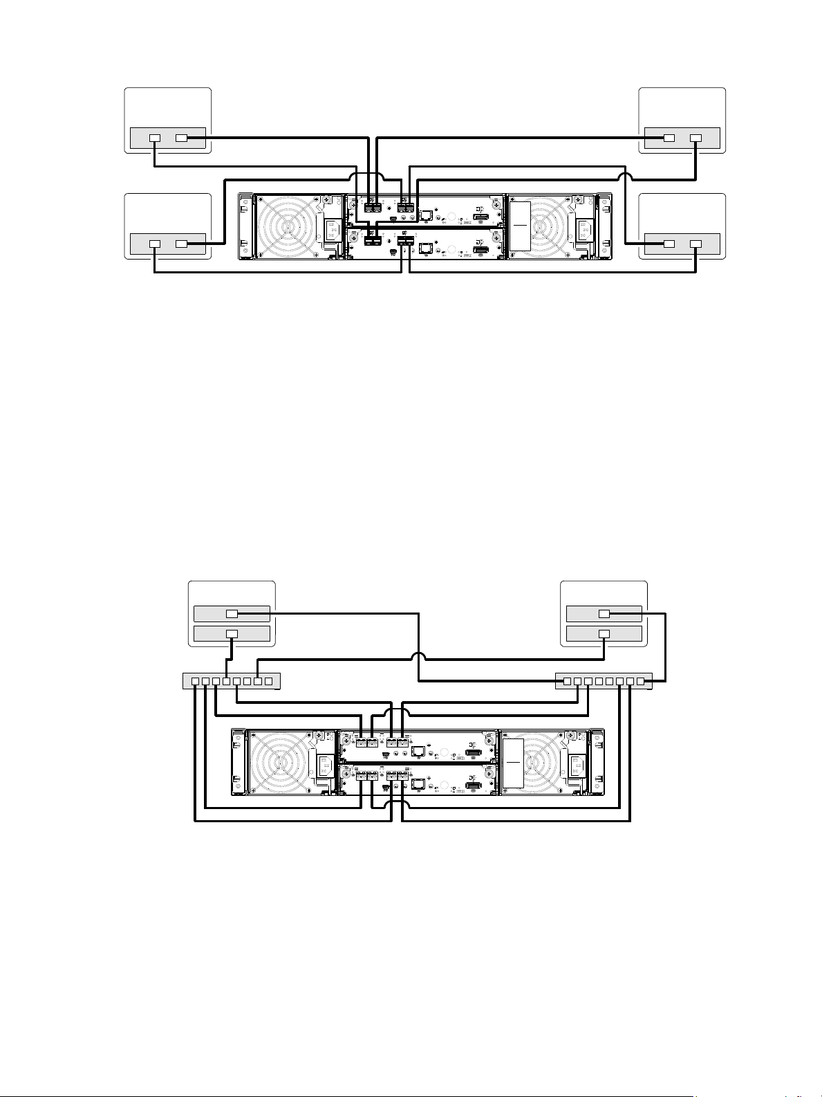
Figure 26 Connecting hosts: direct attach—four servers/one HBA per server/dual path
12Gb/s
S
S
A
12Gb/s
S
S
A
6Gb/s
S
S
A
6Gb/s
S
S
A
12Gb/s
S
S
A
12Gb/s
S
S
A
4544
Server 2
0A
0B
Server 1
Server 4Server 3
6Gb/s
S
S
A
6Gb/s
S
S
A
4844
Server 1
Server 2
Switch A
Switch B
0A
0B
Connecting switch attach configurations
A switch attach solution—or SAN—places a switch between the servers and the controller enclosures
within the storage system.
Using switches, a SAN shares a storage system among multiple servers, reducing the number of storage
systems required for a particular environment. Using switches increases the number of servers that can be
connected to the storage system. A Ultra48 Series controller enclosure supports 64 hosts.
The diagrams that follow show the SAN by using labeled switches and by using a cloud symbol to denote
a SAN fabric.
Dual-controller configuration
Two servers/two switches
38 Connecting hosts
Figure 27 Connecting hosts: switch attach—two servers/two switches
Page 39
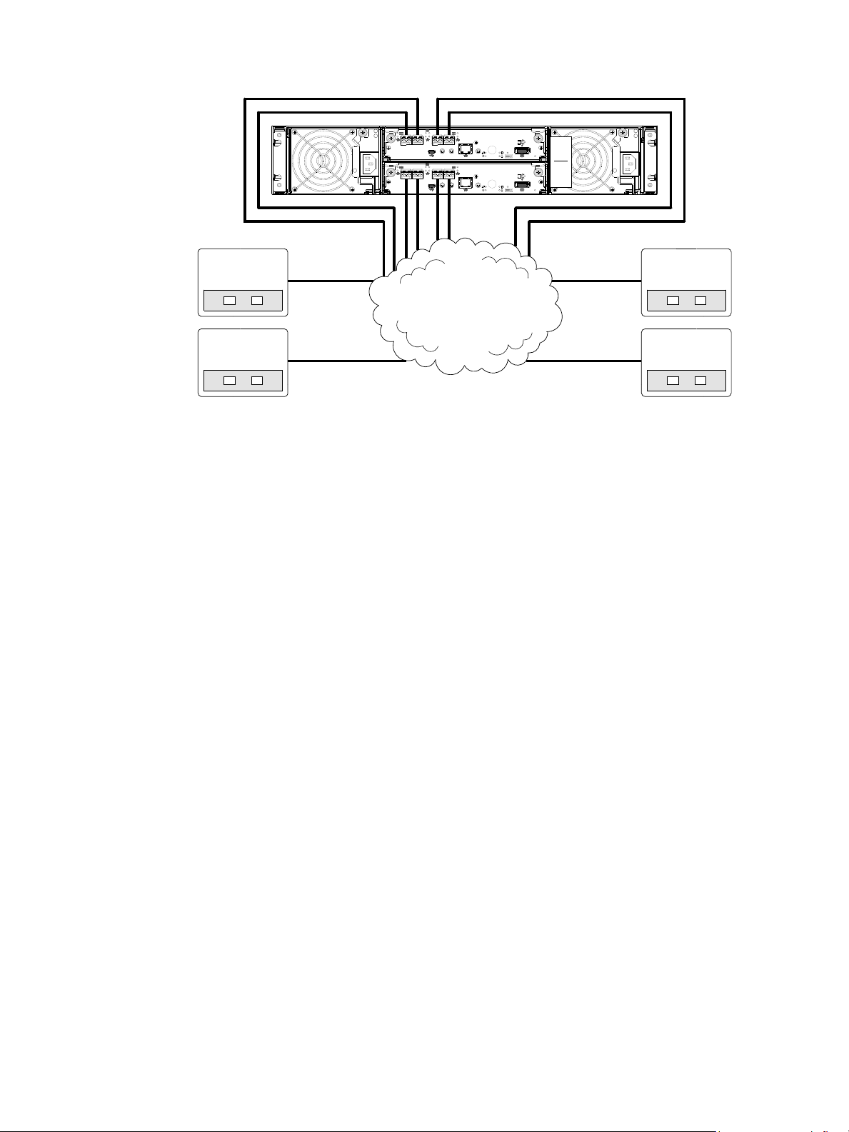
Four servers/multiple switches/SAN fabric
6Gb/s
S
S
A
6Gb/s
S
S
A
4844
Server 1
Server 2
SAN
0A
0B
Server 3
Server 4
Figure 28 Connecting hosts: switch attach—four servers/multiple switches/SAN fabric
Ultra48 Series controller enclosure iSCSI considerations
When installing an Ultra48 Series iSCSI controller enclosure, use at least three ports per server—two for
the storage LAN, and one or more for the public LAN(s)—to ensure that the storage network is isolated
from the other networks. The storage LAN is the network connecting the servers—via switch attach—to the
controller enclosure (see Figure 27 on page 38 and Figure 28).
IP address scheme for the controller pair — two iSCSI ports per controller
The 4844 can use port 2 of each controller as one failover pair, and port 3 of each controller as a second
failover pair for 1Gb iSCSI traffic. Port 2 of each controller must be in the same subnet, and port 3 of each
controller must be in second subnet. See Figure 7 on page 19 for iSCSI port numbering.
For example (with a netmask of 255.255.255.0):
• C on tro ll er A p or t 2: 10 .10.10.100
• Controller A port 3: 10.11.10.120
• C on tro ll er B p or t 2: 10.10.10.110
• C on tro ll er B p or t 3 : 10 .11.10 .130
The 4844 can use port 0 of each controller as one failover pair, and port 1 of each controller as a second
failover pair. Port 0 of each controller must be in the same subnet, and port 1 of each controller must be in
second subnet. See Figure 7 on page 19 for iSCSI port numbering.
For example (with a netmask of 255.255.255.0):
• Controller A port 0: 10.10.10.100
• C on tro ll er A p or t 1: 10 .11.10.120
• Controller B port 0: 10.10.10.110
• C on tr o ll er B p or t 1: 10 .11.10 .13 0
IP address scheme for the controller pair — four iSCSI ports per controller
When all CNC ports are configured for iSCSI, the scheme is similar to the one described for two-ports
above. See Figure 7 on page 19 for iSCSI port numbering.
For example (with a netmask of 255.255.255.0):
• Controller A port 0: 10.10.10.100
• C on tro ll er A p or t 1: 10 .11.10.120
• C on tro ll er A p or t 2: 10 .10.10.110
AssuredSAN Ultra48 Series Setup Guide 39
Page 40

• Controller A port 3: 10.11.10.130
• Controller B port 0: 10.10.10.140
• C on tr o ll er B p or t 1: 10 .11.10 .15 0
• Controller B port 2: 10.10.10.160
• C on tro ll er B p or t 3 : 10 .11.10 .170
In addition to setting the port-specific options described above, you can also set common options. In
RAIDar‘s Configuration View panel, right-click the system and select Configuration > System Settings >
Host Interfaces.
help.
See the “To change iSCSI host interface settings” topic within the RAIDar user guide or online
Connecting a management host on the network
The management host directly manages storage systems out-of-band over an Ethernet network.
1. Connect an RJ-45 Ethernet cable to the network port on each controller.
2. Connect the other end of each Ethernet cable to a network that your management host can access
(preferably on the same subnet).
NOTE: Connections to this device must be made with shielded cables—grounded at both ends—with
metallic
AssuredSAN Product Regulatory Compliance and Safety (included in your product’s ship kit).
RFI/EMI connector hoods, in order to maintain compliance with FCC Rules and Regulations. See
Alternatively, you can access the document online. See Dot Hill’s customer resource center (CRC) web site
for additional information: http://crc.dothill.com
Select AssuredSAN & R/Evolution Products > 4004 Series to download the PRC&S document.
.
Connecting two storage systems to replicate volumes
AssuredRemote™ replication is a licensed disaster-recovery feature that performs asynchronous (batch)
replication of block-level data from a volume on a local (primary) storage system to a volume that can be
on the same system or a second, independent system. The second system can be located at the same site
as the first system, or at a different site.
The two associated standard volumes form a replication set, and only the primary volume (source of data)
can be mapped for access by a server. Both systems must be licensed to use AssuredRemote, and must be
connected through switches to the same fabric or network (i.e., no direct attach). The server accessing the
replication set need only be connected to the primary system. If the primary system goes offline, a
connected server can access the replicated data from the secondary system.
Replication configuration possibilities are many, and can be cabled—in switch attach fashion—to support
the CNC-based 4844 systems on the same network, or on physically-split networks (4544 SAS systems do
not support replication). As you consider the physical connections of your system—specifically connections
for replication—keep several important points in mind:
• Ensure that controllers have connectivity between systems, whether local or remote.
• Assign specific ports for replication whenever possible. By specifically assigning ports available for
replication, you free the controller from scanning and assigning the ports at the time replication is
performed.
• For remote replication, ensure that all ports assigned for replication are able to communicate
appropriately with the remote replication system (see verify remote-link in the CLI Reference Guide for
more information).
• Allow two ports to perform replication. This permits the system to balance the load across those ports as
I/O demands rise and fall. On dual-controller enclosures, if some of the volumes replicated are owned
by controller A and others are owned by controller B, then allow at least one port for replication on
each controller module—and possibly more than one port per controller module—depending on
replication traffic load.
40 Connecting hosts
Page 41

• Be sure of the desired link type before creating the replication set, because you cannot change the
replication link type after creating the replication set.
• For the sake of system security, do not unnecessarily expose the controller module network port to an
external network connection.
Conceptual cabling examples are provided addressing cabling on the same network and cabling relative
to physically-split networks.
IMPORTANT: AssuredRemote must be licensed on all systems configured for replication, and the controller
module firmware must be compatible on all systems licensed for replication.
NOTE: Systems must be correctly cabled before performing replication. See the following documents for
more information about using AssuredRemote to perform replication tasks.
• AssuredSAN 4004 Series RAIDar User Guide
• AssuredSAN 4004 Series CLI Reference Guide
Cabling for replication
This section shows example replication configurations for CNC-based 4844 controller enclosures. The
following illustrations provide conceptual examples of cabling to support AssuredRemote replication. Blue
cables show I/O traffic and green cables show replication traffic.
NOTE: A simplified version of the controller enclosure rear panel is used in cabling illustrations to portray
either FC or iSCSI host interface protocol. The rear panel layouts for the three CNC models are identical;
only the external connectors used in the host interface ports differ.
Once the 4844 systems are physically cabled, see the AssuredSAN 4004 Series RAIDar User Guide or
online help for information about configuring, provisioning, and using the optional AssuredRemote feature.
NOTE: The RAIDar Replication Setup Wizard guides you through replication setup.
CNC ports and replication
CNC controller modules can use qualified SFP options of the same type, or they can use a combination of
qualified SFP options supporting different interface protocols. If you use a combination of different
protocols, then CNC ports 0 and 1 must be set to FC (either both16 Gbit/s or both 8 Gbit/s), and CNC
ports 2 and 3 must be set to iSCSI (either both 10GbE or both 1 Gbit/s). Each CNC port can perform I/O
or replication. In combination environments one interface—for example FC—might be used for I/O, and
the other interface type—10GbE or 1 Gb iSCSI—might be used for replication.
AssuredSAN Ultra48 Series Setup Guide 41
Page 42
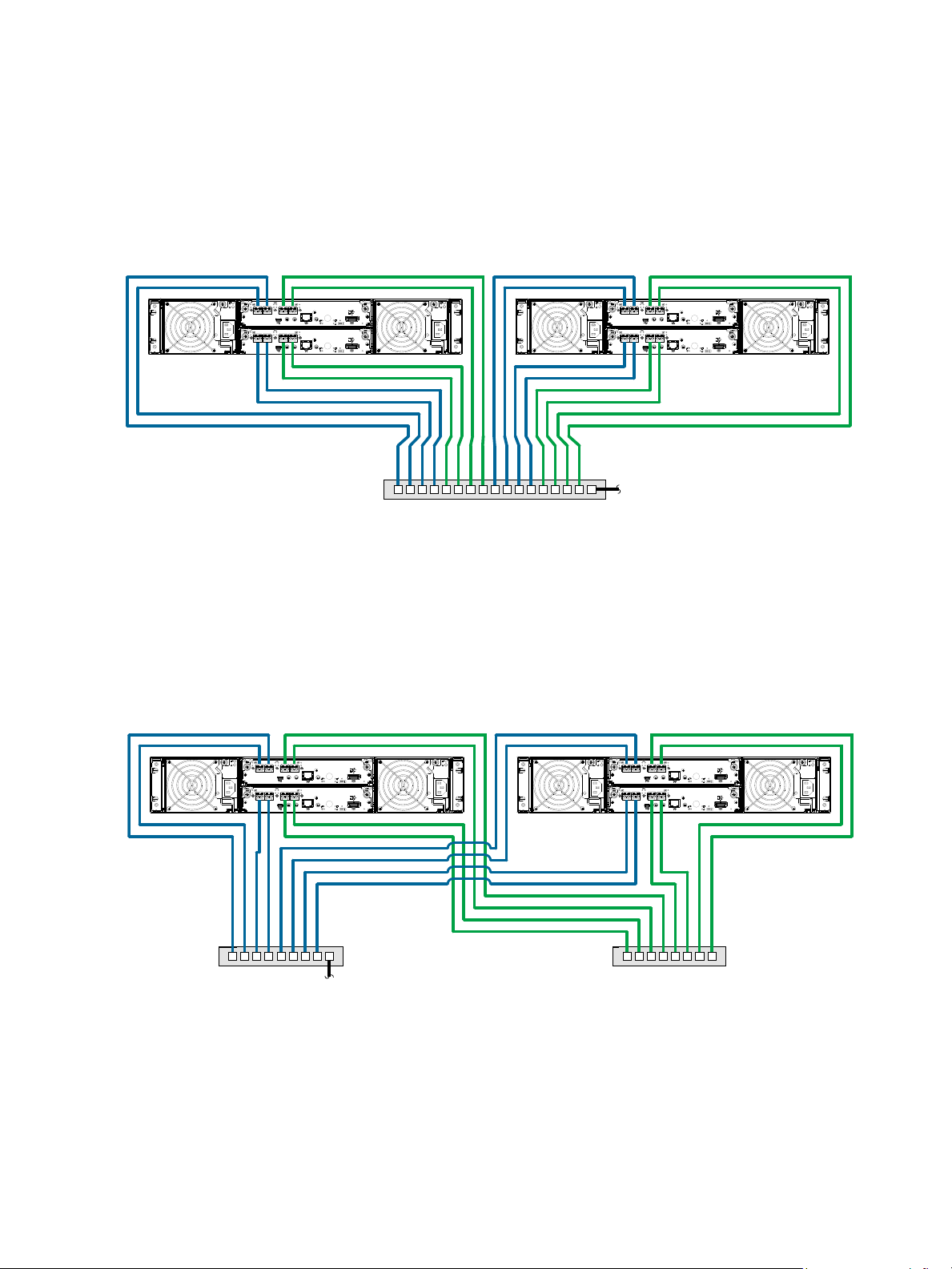
Dual-controller configuration
6Gb/s
S
S
A
6Gb/s
S
S
A
6Gb/s
S
S
A
6Gb/s
S
S
A
4844 controller enclosure
Switch To host server(s)
4844 controller enclosure
6Gb/s
S
S
A
6Gb/s
S
S
A
6Gb/s
S
S
A
6Gb/s
S
S
A
4844 controller enclosure 4844 controller enclosure
To host server(s)
I/O switch
Switch
(replication)
Each of the following diagrams show the rear panel of two 4844 controller enclosures equipped with
dual-controller modules. The controller modules can use qualified SFP options of the same type, or they can
use a combination of qualified SFP options supporting different interface protocols.
Multiple servers/single network
The diagram below shows the rear panel of two 4844 controller enclosures with both I/O and replication
occurring on the same physical network.
Figure 29 Connecting two storage systems for AssuredRemote: multiple servers/one switch/one location
The diagram below shows CNC host interface connections and CNC-based replication, with I/O and
replication occurring on different networks. For optimal protection, use two switches. Connect two ports
from each controller module to the first switch to facilitate I/O traffic, and connect two ports from each
controller module to the second switch to facilitate replication. Using two switches in tandem avoids the
potential single point of failure inherent to using a single switch; however, of one switch fails, either I/O or
replication will fail, depending on which of the switches fails.
Figure 30 Connecting two storage systems for AssuredRemote: multiple servers/switches/one location
Virtual Local Area Network (VLAN) and zoning can be employed to provide separate networks for iSCSI
and FC, respectively. Whether using a single switch or multiple switches for a particular interface, you can
create a VLAN or zone for I/O and a VLAN or zone for replication to isolate I/O traffic from replication
traffic. Since each switch would include both VLANs or zones, the configuration would function as multiple
networks.
42 Connecting hosts
Page 43
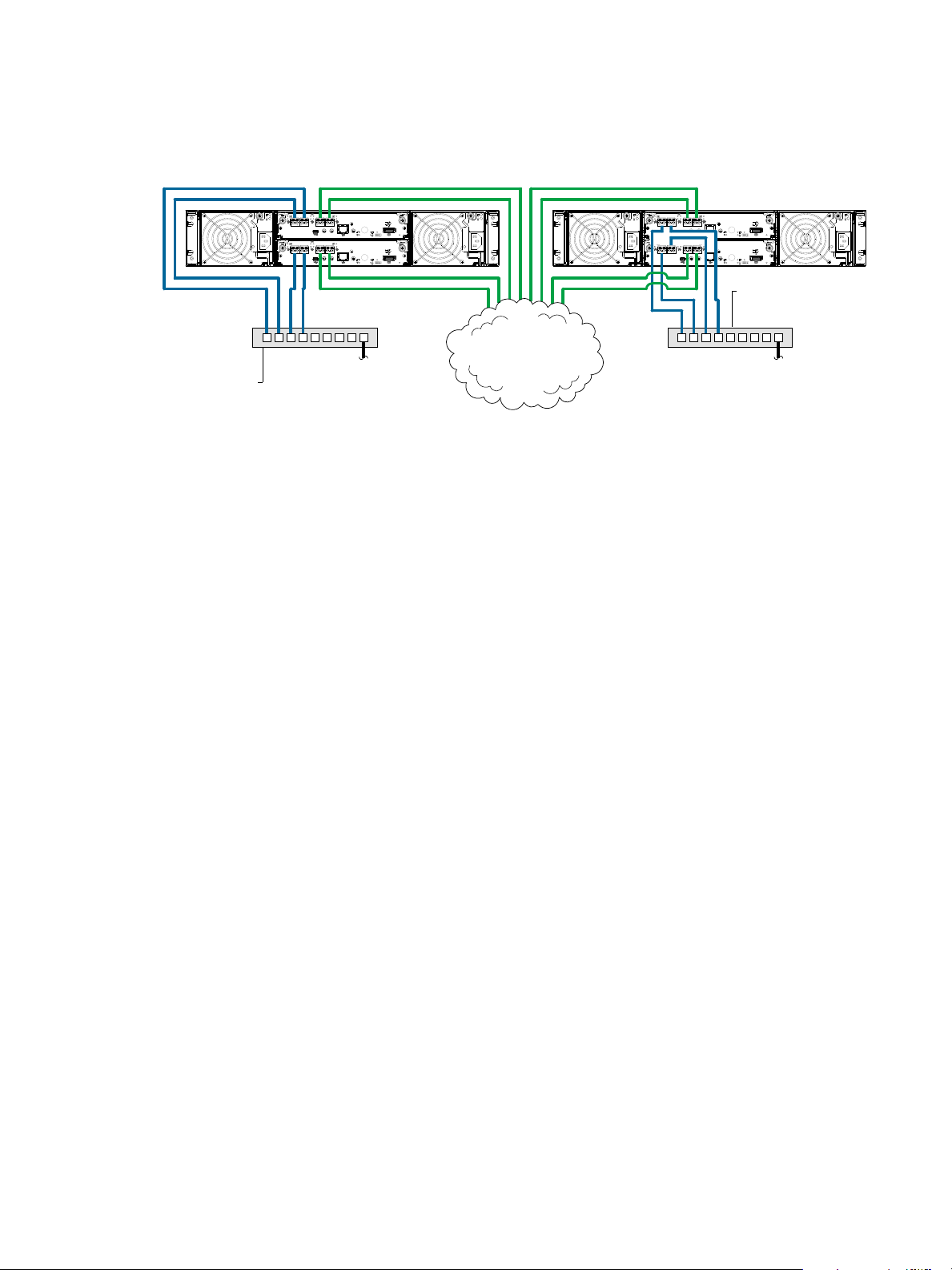
Multiple servers/different networks/multiple switches
6Gb/s
S
S
A
6Gb/s
S
S
A
6Gb/s
S
S
A
6Gb/s
S
S
A
Remote site "A"
CNC
I/O switch
To host servers
Remote site "B"
To host servers
CNC
I/O switch
Peer sites with failover
4844 controller enclosure 4844 controller enclosure
WAN
Ethernet
The diagram below shows the rear panel of two 4844 controller enclosures with I/O and replication
occurring on different networks.
Figure 31 Connecting two storage systems for AssuredRemote: multiple servers/switches/two locations
The diagram entitled “Connecting two storage systems for AssuredRemote: multiple servers/SAN
fabric/two locations” (Figure 32 on page 44) shows the rear-panel of two 4844 controller enclosures with
both I/O and replication occurring on different networks.
This diagram represents two branch offices cabled to enable disaster recovery and backup. In case of
failure at either the local site or the remote site, you can fail over the application to the available site.
AssuredSAN Ultra48 Series Setup Guide 43
Page 44
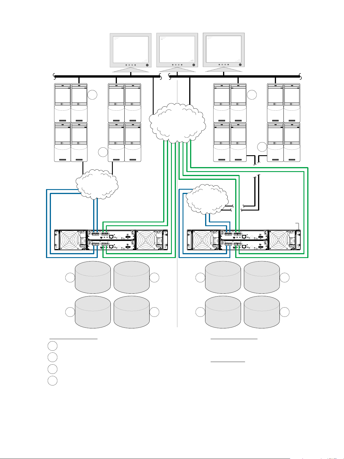
6Gb/s
S
S
A
6Gb/s
S
S
A
6Gb/s
S
S
A
6Gb/s
S
S
A
Peer sites with failover
Key — Server Codes:
= "A" File servers
Data Restore Modes:
- Replicate back over WAN
- Replicate via physical media transfer
Failover Modes
- VMware
- Hyper V failover to servers
A
1
A
2
B
2
A
1
B
1
A
2
B
2
A
1
B
1
A
1
A
2
B
1
B
2
= "A" Application servers
A
2
= "B" File servers
B
1
= "B" Application servers
B
2
Remote site “B”
Remote site “A”
Corporate
end-users
Corporate
end-users
LAN
LAN
WAN
Ethernet
SAN
FC
SAN
FC
data
FS “A”
data
App “A”
replica
App “B”
replica
FS “B”
replica
FS “A”
replica
App “A”
data
FS “B”
data
App “B”
4844 storage
system (typ. 2 places)
44 Connecting hosts
Although not shown in the preceding cabling examples, you can cable replication-enabled 4844 systems
and compatible 4004 Series systems—via switch attach—for performing replication tasks.
Figure 32 Connecting two storage systems for AssuredRemote: multiple servers/SAN fabric/two locations
Page 45

Updating firmware
After installing the hardware and powering on the storage system components for the first time, verify that
the controller modules, expansion modules, and disk drives are using the current firmware release. Using
RAIDar, right-click the system in the Configuration View panel, and select Tools > Update Firmware. The
Update Firmware panel displays the currently installed firmware versions, and allows you to update them.
Optionally, you can update firmware using FTP (File Transfer Protocol) as described in the AssuredSAN
4004 Series RAIDar User Guide.
IMPORTANT: See the “Updating firmware” topic in the AssuredSAN 4004 Series RAIDar User Guide
before performing a firmware update.
Obtaining IP values
You can configure addressing parameters for each controller module’s network port. You can set static IP
values or use DHCP.
TIP: See the “Configuring network ports” topic in the AssuredSAN 4004 Series RAIDar User Guide.
Setting network port IP addresses using DHCP
In DHCP mode, network port IP address, subnet mask, and gateway values are obtained from a DHCP
server if one is available. If a DHCP server is unavailable, current addressing is unchanged. You must have
some means of determining what addresses have been assigned, such as the list of bindings on the DHCP
server.
Because DHCP is disabled by default in Ultra48 Series systems, you must either use the CLI (Command-line
Interface) to change controller IP address settings, or use RAIDar’s Configuration Wizard as described in
the Using the Configuration Wizard topic in the RAIDar User Guide or online help.
Setting network port IP addresses using the CLI port and cable
If you did not use DHCP to set network port IP values, set them manually (default method) as described
below. If you are using the USB CLI port and cable, you will need to enable the port for communication
(also see Using the CLI port and cable—known issues on Windows on page 93).
Network ports on controller module A and controller module B are configured with the following default
values:
• Network port IP address: 10.0.0.2 (controller A), 10.0.0.3 (controller B)
•IP subnet mask: 255.255.255.0
• Gateway IP address: 10.0.0.1
If the default IP addresses are not compatible with your network, you must set an IP address for each
network port using the CLI embedded in each controller module. The CLI enables you to access the system
using the USB (Universal Serial Bus) communication interface and terminal emulation software.
NOTE: If you are using the mini USB CLI port and cable, see Appendix D - USB device connection:
• Windows customers should download and install the device driver as described in Obtaining the
software download on page 92.
• Linux customers should prepare the USB port as described in Setting parameters for the device driver on
page 93.
Use the CLI commands described in the steps below to set the IP address for the network port on each
controller module.
AssuredSAN Ultra48 Series Setup Guide 45
Page 46
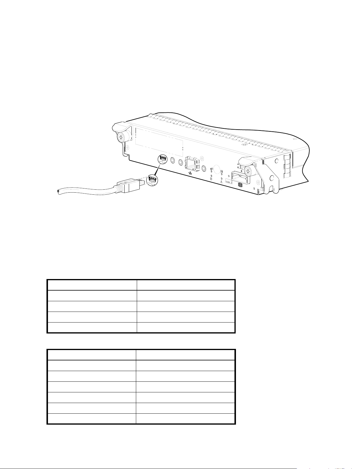
Once new IP addresses are set, you can change them as needed using RAIDar. Be sure to change the IP
CACHE
LINK
DIRTY
LINK
ACT
CLI
CLI
Host Interface
Not Shown
SERVICE−2
SERVICE−1
6Gb/s
Connect USB cable to CLI
port on controller face plate
address via RAIDar before changing the network configuration. See Accessing RAIDar on page 51 for
more information concerning the web-based storage management application.
1. From your network administrator, obtain an IP address, subnet mask, and gateway address for
controller A and another for controller B.
Record these IP addresses so you can specify them whenever you manage the controllers using RAIDar
or the CLI.
2. Use the provided USB cable to connect controller A to a USB port on a host computer. The USB mini 5
male connector plugs into the CLI port as shown in Figure 33 on page 46 (generic Ultra48 Series
controller module shown).
Figure 33 Connecting a USB cable to the CLI port
3. Enable the CLI port for subsequent communication:
• Linux customers should enter the command syntax provided in Setting parameters for the device
driver on page 93.
• Windows customers should locate the downloaded device driver described in Obtaining the
software download on page 92, and follow the instructions provided for proper installation.
4. Start and configure a terminal emulator, such as HyperTerminal or VT-100, using the display settings in
Table 4 and the connection settings in Table 5 (also, see the note following this procedure).
Table 4 Terminal emulator display settings
Parameter Value
Terminal emulation mode VT-100 or ANSI (for color support)
Font Terminal
Translations None
Columns 80
Table 5 Terminal emulator connection settings
Parameter Value
Connector COM3 (for example)
1, 2
Baud rate 115,200
Data bits 8
Parity N one
Stop bits 1
Flow control None
1
Your server or laptop configuration determines which COM port is used for Disk Array USB Port.
2
Verify the appropriate COM port for use with the CLI.
46 Connecting hosts
Page 47

5. In the terminal emulator, connect to controller A.
6. Press Enter to display the CLI prompt (#).
The CLI displays the system version, MC version, and login prompt:
a. At the login prompt, enter the default user
b. Enter the default password
!manage.
manage.
If the default user or password—or both—have been changed for security reasons, enter the secure
login credentials instead of the defaults shown above.
7. At the prompt, enter the following command to set the values you obtained in step 1 for each Network
port, first for controller A, and then for controller B:
set network-parameters ip
address
netmask
netmask
gateway
gateway
controller a|b
where:
•
address
•
netmask
•
gateway
is the IP address of the controller
is the subnet mask
is the IP address of the subnet router
• a|b specifies the controller whose network parameters you are setting
For example:
# set network-parameters ip 192.168.0.10 netmask 255.255.255.0 gateway
192.168.0.1 controller a
# set network-parameters ip 192.168.0.11 netmask 255.255.255.0 gateway
192.168.0.1 controller b
8. Enter the following command to verify the new IP addresses:
show network-parameters
Network parameters, including the IP address, subnet mask, and gateway address are displayed for
each controller.
9. Use the ping command to verify connectivity to the gateway address.
For example:
# ping 192.168.0.1
Info: Pinging 192.168.0.1 with 4 packets.
Success: Command completed successfully. - The remote computer responded with 4
packets.(2011-12-19 10:20:37)
10. In the host computer's command window, type the following command to verify connectivity, first for
controller A and then for controller B:
ping controller-
IP-address
If you cannot access your system for at least three minutes after changing the IP address, you might
need to restart the Management Controller(s) using the serial CLI.
When you restart a Management Controller, communication with it is temporarily lost until it
successfully restarts.
Enter the following command to restart the Management Controller in both controllers:
restart mc both
IMPORTANT: When configuring an iSCSI system or a system using a combination of FC and iSCSI
SFPs, do not restart the Management Controller or exit the terminal emulator session until
configuring the CNC ports as described in Change the CNC port mode on page 48.
11 . When you are done using the CLI, exit the emulator.
12 . Retain the IP addresses (recorded in step 1) for accessing and managing the controllers using either
RAIDar or the CLI.
AssuredSAN Ultra48 Series Setup Guide 47
Page 48

NOTE: Using HyperTerminal with the CLI on a Microsoft Windows host:
On a host computer connected to a controller module’s mini-USB CLI port, incorrect command syntax in a
HyperTerminal session can cause the CLI to hang. To avoid this problem, use correct syntax, use a different
terminal emulator, or connect to the CLI using telnet rather than the mini-USB cable.
Be sure to close the HyperTerminal session before shutting down the controller or restarting its Management
Controller. Otherwise, the host’s CPU cycles may rise unacceptably.
If communication with the CLI is disrupted when using an out-of-band cable connection, communication
can sometimes be restored by disconnecting and reattaching the mini-USB CLI cable as described in step 2
and Figure 33 on page 46.
Change the CNC port mode
This subsection applies to 4844 models only. While the USB cable is still connected and the terminal
emulator session remains active, perform the following steps to change the CNC port mode from the
default setting (FC), to either iSCSI or FC-and-iSCSI used in combination.
When using FC SFPs and iSCSI SFPs in combination, host ports 0 and 1 are set to FC (either both 16
Gbits/s or both 8 Gbit/s), and host ports 2 and 3 must be set to iSCSI (either both 10GbE or both 1
Gbit/s).
Set CNC port mode to iSCSI
To set the CNC port mode for use with iSCSI SFPs, run the following command at the command prompt:
set host-port-mode iSCSI
The command notifies you that it will change host port configuration, stop I/O, and restart both controllers.
When asked if you want to continue, enter y to change the host port mode to use iSCSI SFPs.
Once the set host-port-mode command completes, it will notify you that the specified system host
port mode was set, and that the command completed successfully.
Continue with step 11 of Setting network port IP addresses using the CLI port and cable.
Set CNC port mode to FC and iSCSI
To set the CNC port mode for use with FC SFPs and iSCSI SFPs in combination, run the following command
at the command prompt:
set host-port-mode FC-and-iSCSI
The command notifies you that it will change host port configuration, stop I/O, and restart both controllers.
When asked if you want to continue, enter y to change the host port mode to use FC and iSCSI SFPs.
Once the set host-port-mode command completes, it will notify you that the specified system host
port mode was set, and that the command completed successfully.
Continue with step 11 of Setting network port IP addresses using the CLI port and cable.
Configure the system
NOTE:
• After using either of the CLI command sequences shown above, you may see events stating that the
SFPs installed are not compatible with the protocol set for the host ports. The new host port mode
setting will be synchronized with the qualified SFP option once the controller modules restart.
• See Appendix E—SFP option for CNC ports for instructions about locating and installing your qualified
SFP transceivers within the CNC ports.
48 Connecting hosts
Page 49

After changing the CNC port mode, you can invoke RAIDar and use the Configuration Wizard to initially
configure the system, or change system configuration settings as described in the AssuredSAN 4004
Series RAIDar User Guide and Basic operation.
AssuredSAN Ultra48 Series Setup Guide 49
Page 50

50 Connecting hosts
Page 51
4 Basic operation
Verify that you have successfully completed the sequential “Installation Checklist” instructions in Table 3 on
page 23. Once you have successfully completed steps 1 through 8 therein, you can access the
management interfaces using your web-browser, to complete the system setup.
Accessing RAIDar
Upon completing the hardware installation, you can access the controller module’s web-based
management interface, RAIDar, to configure, monitor, and manage the storage system. Invoke your web
browser, and enter the IP address of the controller module’s network port in the address field (obtained
during completion of “Installation Checklist” step 8), then press Enter. To sign-in to RAIDar, use the default
user name manage and password !manage. If the default user or password—or both—have been
changed for security reasons, enter the secure login credentials instead of the defaults shown above. This
brief Sign In discussion assumes proper web browser setup.
IMPORTANT: For detailed information on accessing and using RAIDar, see the “Getting Started” section
in the web-posted AssuredSAN 4004 Series RAIDar User Guide.
In addition to summarizing the processes to configure and provision a new system for the first time—using
the wizards—the Getting Started section provides instructions for signing in to RAIDar, introduces key
system concepts, addresses browser setup, and provides tips for using the main window and the help
window.
TIP: After signing-in to RAIDar, you can use online help as an alternative to consulting the user guide.
Configuring and provisioning the storage system
Once you have familiarized yourself with RAIDar, use it to configure and provision the storage system. If
you are licensed to use the optional AssuredRemote feature, you may also need to set up the storage
systems for replication. Refer to the following chapters within the RAIDar user guide or online help:
• Getting started
• Configuring the system
• Provisioning the system
• Using AssuredRemote to replicate volumes
NOTE: See the “Installing a license” topic within the RAIDar User Guide for instructions about creating a
temporary license, or installing a permanent license.
IMPORTANT: If the system is used in a VMware environment, set the system’s Missing LUN Response
option to use its Illegal Request setting. To do so, see either the configuration topic “Changing the missing
LUN response” in the RAIDar user guide or the command topic “set-advanced-settings” in the CLI Reference
Guide.
AssuredSAN Ultra48 Series Setup Guide 51
Page 52

52 Basic operation
Page 53

5Troubleshooting
USB CLI port connection
AssuredSAN Ultra48 Series controllers feature a CLI port employing a mini-USB Type B form factor. If you
encounter problems communicating with the port after cabling your computer to the USB device, you may
need to either download a device driver (Windows), or set appropriate parameters via an operating
system command (Linux). See Appendix D for more information.
Fault isolation methodology
AssuredSAN Ultra48 Series storage systems provide many ways to isolate faults. This section presents the
basic methodology used to locate faults within a storage system, and to identify the pertinent FRUs (Field
Replaceable Units) affected.
As noted in Basic operation on page 51, use RAIDar to configure and provision the system upon
completing the hardware installation. As part of this process, configure and enable event notification so the
system will notify you when a problem occurs that is at or above the configured severity (see “Using the
Configuration Wizard > Configuring event notification” within the AssuredSAN Series 4004 RAIDar User
Guide). With event notification configured and enabled, you can follow the recommended actions in the
notification message to resolve the problem, as further discussed in the options presented below.
Basic steps
The basic fault isolation steps are listed below:
• Gather fault information, including using system LEDs
(see Gather fault information on page 54)
• Determine where in the system the fault is occurring
(see Determine where the fault is occurring on page 54)
• Review event logs
(see Review the event logs on page 54)
• If required, isolate the fault to a data path component or configuration
(see Isolate the fault on page 55)
Cabling systems to enable use of the licensed AssuredRemote feature—to replicate volumes—is another
important fault isolation consideration pertaining to initial system installation. See Isolating AssuredRemote
replication faults on page 64 for more information about troubleshooting during initial setup.
Options available for performing basic steps
When performing fault isolation and troubleshooting steps, select the option or options that best suit your
site environment. Use of any option (four options are described below) is not mutually-exclusive to the use
of another option. You can use RAIDar to check the health icons/values for the system and its components
to ensure that everything is okay, or to drill down to a problem component. If you discover a problem, both
RAIDar and the CLI provide recommended-action text online. Options for performing basic steps are listed
according to frequency of use:
• Use RAIDar
• Use the CLI
• Monitor event notification
• View the enclosure LEDs
Use RAIDar
RAIDar uses health icons to show OK, Degraded, Fault, or Unknown status for the system and its
components. RAIDar enables you to monitor the health of the system and its components. If any component
has a problem, the system health will be Degraded, Fault, or Unknown. Use RAIDar’s GUI to drill down to
AssuredSAN Ultra48 Series Setup Guide 53
Page 54

find each component that has a problem, and follow actions in the component Health Recommendations
field to resolve the problem.
Use the CLI
As an alternative to using RAIDar, you can run the show system command in the CLI to view the health of
the system and its components. If any component has a problem, the system health will be Degraded,
Fault, or Unknown, and those components will be listed as Unhealthy Components. Follow the
recommended actions in the component Health Recommendations field to resolve the problem.
Monitor event notification
With event notification configured and enabled, you can view event logs to monitor the health of the
system and its components. If a message tells you to check whether an event has been logged, or to view
information about an event in the log, you can do so using either RAIDar or the CLI. Using RAIDar, you
would view the event log and then click on the event message to see detail about that event. Using the CLI,
you would run the
the detail for an event.
show events detail command (with additional parameters to filter the output) to see
View the enclosure LEDs
You can view the LEDs on the hardware (while referring to LED descriptions for your enclosure model) to
identify component status. If a problem prevents access to either RAIDar or the CLI, this is the only option
available. However, monitoring/management is often done at a management console using storage
management interfaces, rather than relying on line-of-sight to LEDs of racked hardware components.
Performing basic steps
You can use any of the available options described above in performing the basic steps comprising the
fault isolation methodology.
Gather fault information
When a fault occurs, it is important to gather as much information as possible. Doing so will help you
determine the correct action needed to remedy the fault.
Begin by reviewing the reported fault:
•
Is the fault related to an internal data path or an external data path?
• Is the fault related to a hardware component such as a disk drive module, controller module, or power
supply unit?
By isolating the fault to one of the components within the storage system, you will be able to determine the
necessary corrective action more quickly.
Determine where the fault is occurring
Once you have an understanding of the reported fault, review the enclosure LEDs. The enclosure LEDs are
designed to immediately alert users of any system faults, and might be what alerted the user to a fault in
the first place.
When a fault occurs, the Fault ID status LED on an enclosure’s right ear illuminates (see the diagram
pertaining to your product’s front panel components on page 15). Check the LEDs on the back of the
enclosure to narrow the fault to a FRU, connection, or both. The LEDs also help you identify the location of
a FRU reporting a fault.
Use RAIDar to verify any faults found while viewing the LEDs. RAIDar is also a good tool to use in
determining where the fault is occurring if the LEDs cannot be viewed due to the location of the system.
RAIDar provides you with a visual representation of the system and where the fault is occurring. It can also
provide more detailed information about FRUs, data, and faults.
Review the event logs
The event logs record all system events. Each event has a numeric code that identifies the type of event that
occurred, and has one of the following severities:
• Critical. A failure occurred that may cause a controller to shut down. Correct the problem immediately.
54 Troubleshooting
Page 55

• Error. A failure occurred that may affect data integrity or system stability. Correct the problem as soon
as possible.
• Warning. A problem occurred that may affect system stability, but not data integrity. Evaluate the
problem and correct it if necessary.
• Informational. A configuration or state change occurred, or a problem occurred that the system
corrected. No immediate action is required.
See the AssuredSAN Event Descriptions Reference Guide for information about specific events.
See Dot Hill’s Customer Resource Center web site for additional information: http://crc.dothill.com
Select AssuredSAN & R/Evolution Products > 4004 Series to download the Event Descriptions guide.
The event logs record all system events. It is very important to review the logs, not only to identify the fault,
but also to search for events that might have caused the fault to occur. For example, a host could lose
connectivity to a virtual disk if a user changes channel settings without taking the storage resources
assigned to it into consideration. In addition, the type of fault can help you isolate the problem to either
hardware or software.
Isolate the fault
Occasionally, it might become necessary to isolate a fault. This is particularly true with data paths, due to
the number of components comprising the data path. For example, if a host-side data error occurs, it could
be caused by any of the components in the data path: controller module, cable, or data host.
If the enclosure does not initialize
It may take up to two minutes for all enclosures to initialize. If an enclosure does not initialize:
• Perform a rescan
• Power cycle the system
• Make sure the power cord is properly connected, and check the power source to which it is connected
• Check the event log for errors
Correcting enclosure IDs
When installing a system with drive enclosures attached, the enclosure IDs might not agree with the
physical cabling order. This is because the controller might have been previously attached to enclosures in
a different configuration, and it attempts to preserve the previous enclosure IDs if possible. To correct this
condition, make sure that both controllers are up, and perform a rescan using RAIDar or the CLI. This will
reorder the enclosures, but can take up to two minutes for the enclosure IDs to be corrected.
.
To perform a rescan using the CLI, type the following command:
rescan
To rescan using RAIDar:
1. Verify that controllers are operating normally
2. In the Configuration View panel, right-click the system and select Tools > Rescan Disk Channels
3. Click Rescan
NOTE: The reordering enclosure IDs action only applies to Dual Controller mode. If only one controller is
available, due to either Single Controller configuration or controller failure, a manual rescan will not
reorder the drive enclosure IDs.
Stopping I/O
When troubleshooting disk drive and connectivity faults, stop I/O to the affected vdisks from all hosts and
remote systems as a data protection precaution. As an additional data protection precaution, it is helpful to
conduct regularly scheduled backups of your data.
AssuredSAN Ultra48 Series Setup Guide 55
Page 56
IMPORTANT: Stopping I/O to a vdisk is a host-side task, and falls outside the scope of this document.
When on-site, you can verify that there is no I/O activity by briefly monitoring the system LEDs; however,
when accessing the storage system remotely, this is not possible. Remotely, you can use the
vdisk-statistics
command to determine if input and output has stopped. Perform the steps below:
show
1. Using the CLI, run the
The Number of Reads and Number of Writes outputs show the number of these operations that
have occurred since the statistic was last reset, or since the controller was restarted.
2. Run the
show vdisk-statistics command a second time.
This provides you a specific window of time (the interval between requesting the statistics) to determine
if data is being written to or read from the disk.
3. If any reads or writes occur during this interval, a host is still reading from or writing to this vdisk.
Continue to stop IOPS from hosts, and repeat step 1 until the Number of Reads and Number of
Writes statistics are zero.
NOTE: See AssuredSAN 4004 Series CLI Reference Guide for additional information.
Diagnostic steps
This section describes possible reasons and actions to take when an LED indicates a fault condition during
initial system setup. See Appendix A – LED descriptions for descriptions of all LED statuses.
NOTE: Once event notification is configured and enabled using RAIDar, you can view event logs to
monitor the health of the system and its components using the GUI.
show vdisk-statistics command.
In addition to monitoring LEDs via line-of-sight observation of the racked hardware components when
performing diagnostic steps, you can also monitor the health of the system and its components using the
management interfaces previously discussed. Bear this in mind when reviewing the Actions column in the
following diagnostics tables, and when reviewing the step procedures provided later in this chapter.
Is the enclosure front panel Fault/Service Required LED amber?
Answer Possible reasons Actions
No System functioning properly. No action required.
Yes A fault condition exists/occurred.
If installing an I/O module FRU, the
module has gone online and likely
failed its self-test.
Table 6 Diagnostics LED status: Front panel “Fault/Service Required”
• Check the LEDs on the back of the controller to narrow the
fault to a FRU, connection, or both.
• Check the event log for specific information regarding the
fault; follow any Recommended Actions.
• If installing an IOM FRU, try removing and reinstalling the
new IOM, and check the event log for errors.
• If the above actions do not resolve the fault, isolate the fault,
and contact an authorized service provider for assistance.
Replacement may be necessary.
56 Troubleshooting
Page 57
Is the controller back panel FRU OK LED off?
Answer Possible reasons Actions
No
(blinking)
Yes The controller module is not powered on.
System functioning properly.
System is booting.
The controller module has failed.
No action required.
Wait for system to boot.
• Check that the controller module is fully inserted
and latched in place, and that the enclosure is
powered on.
• Check the event log for specific information
regarding the failure.
Table 7 Diagnostics LED status: Rear panel “FRU OK”
Is the controller back panel Fault/Service Required LED amber?
Answer Possible reasons Actions
No System functioning properly. No action required.
Yes (blinking) One of the following errors
occurred:
• Hardware-controlled power-up error
• Cache flush error
• Cache self-refresh error
Table 8 Diagnostics LED status: Rear panel “Fault/Service Required”
• Restart this controller from the other controller
using RAIDar or the CLI.
• If the above action does not resolve the fault,
remove the controller module and reinsert it.
• If the above action does not resolve the fault,
contact an authorized service provider for
assistance. It may be necessary to replace the
controller module.
Is the drawer panel Fault/Service Required LED amber?
Answer Possible reasons Actions
No System functioning properly. No action required.
Yes (solid) A drawer-level fault is detected or a
service action is required.
Yes (blink) Hardware-controlled power-up error • Check the event log for specific information
Table 9 Diagnostics LED status: Drawer panel “Fault/Service Required”
NOTE: Consider the following when troubleshooting drawer LEDs:
• See Enclosure bezel attachment and removal on page 71.
• See Enclosure drawers on page 16.
• The CLI commands
stop drawer and start drawer are used for communicating with enclosure
drawers. See the AssuredSAN 4004 Series CLI Reference Guide for information about command
syntax and usage.
• Check the event log for specific information
regarding the fault; follow any Recommended
Actions.
• If the above action does not resolve the fault,
contact an authorized service provider for
assistance.
regarding the fault; follow any Recommended
Actions.
• If the above action does not resolve the fault,
contact an authorized service provider for
assistance.
AssuredSAN Ultra48 Series Setup Guide 57
Page 58
Is the disk drive module LED off?
Answer Possible reasons Actions
Yes • There is no power.
• The disk drive is offline.
• The disk is not configured.
Check that the disk drive module is fully inserted and
latched in place, and that both the enclosure and the
drawer are powered on.
Table 10 Diagnostics LED status: Disk LED off
NOTE: See Disk drives used in Ultra48 Series enclosures on page 17.
Is the disk drive module LED blinking blue (4Hz blink rate)?
Answer Possible reasons Actions
Yes • The disk has failed or experienced a
fault.
• The disk is a leftover.
• The vdisk that the disk is associated
with is down or critical.
Table 11 Diagnostics LED status: Disk drive module fault status
NOTE: Consider the following when accessing disks:
• See Opening and closing a drawer on page 24.
• See FDE considerations on page 27.
• Check the event log for specific information
regarding the fault; follow any Recommended
Actions.
• Isolate the fault.
• Contact an authorized service provider for
assistance.
Is a connected host port Host Link Status LED off?
Answer Possible reasons Actions
No System functioning properly. No action required (see Link LED note: page 80).
Yes The link is down. • Check cable connections and reseat if necessary.
• Inspect cable for damage.
• Swap cables to determine if fault is caused by a defective
cable. Replace cable if necessary.
• Verify that the switch, if any, is operating properly. If possible,
test with another port.
• Verify that the HBA is fully seated, and that the PCI slot is
powered on and operational.
• In RAIDar, review event logs for indicators of a specific fault in
a host data path component.
• Contact an authorized service provider for assistance.
• See Isolating a host-side connection fault on page 61.
Table 12 Diagnostics LED status: Rear panel “Host Link Status”
58 Troubleshooting
Page 59
Is a connected port Expansion Port Status LED off?
Answer Possible reasons Actions
No System functioning properly. No action required.
Yes The link is down. • Check cable connections and reseat if necessary.
• Inspect cable for damage. Replace cable if necessary.
• Swap cables to determine if fault is caused by a defective
cable. Replace cable if necessary.
• In RAIDar, review the event logs for indicators of a specific
fault in a host data path component.
• Contact an authorized service provider for assistance.
• See Isolating a controller module expansion port connection
fault on page 63.
Table 13 Diagnostics LED status: Rear panel “Expansion Port Status”
Is a connected port’s Network Port link status LED off?
Answer Possible reasons Actions
No System functioning properly. No action required.
Yes The link is down. Use standard networking troubleshooting procedures to isolate
faults on the network.
Table 14 Diagnostics LED status: Rear panel “Network Port Link Status”
Is the power supply Input Power Source LED off?
Answer Possible reasons Actions
No System functioning properly. No action required.
Yes The power supply is not receiving
adequate power.
• Verify that the power cord is properly connected, and check
the power source to which it connects.
• Check that the power supply FRU is firmly locked into
position.
• Check the event log for specific information regarding the
fault.
• If the above action does not resolve the fault, isolate the
fault, and contact an authorized service provider for
assistance.
Table 15 Diagnostics LED status: Rear panel power supply “Input Power Source”
Is the Voltage/Fan Fault/Service Required LED amber?
Answer Possible reasons Actions
No System functioning properly. No action required.
Yes The power supply unit or a fan is
operating at an unacceptable
voltage/RPM level, or has failed.
When isolating faults in the power supply, remember that the
fans in both modules receive power through a common bus on
the midplane, so if a power supply unit fails, the fans continue
to operate normally.
• Verify that the power supply FRU is firmly locked into
position.
• Verify that the power cable is connected to a power source.
• Verify that the power cable is connected to the enclosure’s
power supply unit.
Table 16 Diagnostics LED status: Rear panel power supply “Voltage/Fan Fault/Service Required”
AssuredSAN Ultra48 Series Setup Guide 59
Page 60
Controller failure in a single-controller configuration
This subsection addresses a potential situation that might occur if a partner controller fails following failure
of its peer controller.
IMPORTANT: The Ultra48 Series enclosures support dual-controller environments only. Do not transport
the CompactFlash since data corruption might occur. Single-controller support is provided only when a
controller fails over to its partner controller.
Cache memory is flushed to CompactFlash in the case of a controller failure or power loss. During the write
to CompactFlash process, only the components needed to write the cache to the CompactFlash are
powered by the supercapacitor. This process typically takes 60 seconds per 1 Gbyte of cache. After the
cache is copied to CompactFlash, the remaining power left in the supercapacitor is used to refresh the
cache memory. While the cache is being maintained by the supercapacitor, the Cache Status LED flashes
at a rate of 1/10 second on and 9/10 second off.
If the controller has failed or does not start, is the Cache Status LED on/blinking?
Answer Actions
No, the Cache LED status is off, and the
controller does not boot.
No, the Cache Status LED is off, and the
controller boots.
Yes, at a strobe 1:10 rate - 1 Hz, and the
controller does not boot.
Yes, at a strobe 1:10 rate - 1 Hz, and the
controller boots.
Yes, at a blink 1:1 rate - 1 Hz, and the controller
does not boot.
Yes, at a blink 1:1 rate - 1 Hz, and the controller
boots.
If valid data is thought to be in Flash, see Transporting cache via
professional services; otherwise, replace the controller module.
The system has flushed data to disks. If the problem persists,
replace the controller module.
See Transporting cache via professional services.
The system is flushing data to CompactFlash. If the problem
persists, replace the controller module.
See Transporting cache via professional services.
The system is in self-refresh mode. If the problem persists, replace
the controller module.
Table 17 Diagnostics LED status: Rear panel “Cache Status” (continued)
NOTE: See also Cache Status LED details on page 81.
Transporting cache via professional services
IMPORTANT: Transportable cache only applies to single-controller configurations. In dual-controller
configurations, there is no need to transport a failed controller’s cache to a replacement controller because
the cache is duplicated between the partner controllers (subject to volume write optimization setting).
To preserve the existing data stored in the CompactFlash, you must transport the CompactFlash from the
failed controller to a replacement controller. To transport cache, you must return the controller module to a
maintenance depot for servicing by qualified personnel.
CAUTION: Transporting of cache must be performed by a qualified service technician.
60 Troubleshooting
Page 61

Isolating a host-side connection fault
During normal operation, when a controller module host port is connected to a data host, the port’s host
link status/link activity LED is green. If there is I/O activity, the host activity LED blinks green. If data hosts
are having trouble accessing the storage system, and you cannot locate a specific fault or cannot access
the event logs, use the applicable procedure that follows. These procedures require scheduled downtime.
IMPORTANT: Do not perform more than one step at a time. Changing more than one variable at a time
can complicate the troubleshooting process.
Host-side connection troubleshooting featuring CNC ports
The procedure below applies to AssuredSAN Ultra48 Series controller enclosures employing small form
factor pluggable (SFP) transceiver connectors in 4/8/16 Gb FC, 10GbE iSCSI, or 1 Gb iSCSI host
interface ports. In the following procedure, “SFP and host cable” is used to refer to any of the qualified SFP
options supporting CNC ports used for I/O or replication.
NOTE: When experiencing difficulty diagnosing performance problems, consider swapping out one SFP
at a time to see if performance improves.
1. Halt all I/O to the storage system (see Stopping I/O on page 55).
2. Check the host link status/link activity LED.
If there is activity, halt all applications that access the storage system.
3. Check the Cache Status LED to verify that the controller cached data is flushed to the disk drives.
• Solid – Cache contains data yet to be written to the disk.
• Blinking – Cache data is being written to CompactFlash.
•Flashing at
• Off – Cache is clean (no unwritten data).
4. Remove the SFP and host cable and inspect for damage.
5. Reseat the SFP and host cable.
Is the host link status/link activity LED on?
• Yes – Monitor the status to ensure that there is no intermittent error present. If the fault occurs again,
clean the connections to ensure that a dirty connector is not interfering with the data path.
• No – Proceed to the next step.
6. Move the SFP and host cable to a port with a known good link status.
This step isolates the problem to the external data path (SFP, host cable, and host-side devices) or to the
controller module port.
Is the host link status/link activity LED on?
• Yes – You now know that the SFP, host cable, and host-side devices are functioning properly. Return
the cable to the original port. If the link status LED remains off, you have isolated the fault to the
controller module’s port. Replace the controller module.
• No – Proceed to the next step.
7. Swap the SFP with the known good one.
Is the host link status/link activity LED on?
• Yes – You have isolated the fault to the SFP. Replace the SFP.
• No – Proceed to the next step.
8. Re-insert the original SFP and swap the cable with a known good one.
Is the host link status/link activity LED on?
• Yes – You have isolated the fault to the cable. Replace the cable.
• No – Proceed to the next step.
1/10 second on and 9/10 second off – Cache is being refreshed by the supercapacitor.
AssuredSAN Ultra48 Series Setup Guide 61
Page 62

9. Verify that the switch, if any, is operating properly. If possible, test with another port.
10. Verify that the HBA is fully seated, and that the PCI slot is powered on and operational.
11 . Replace the HBA with a known good HBA, or move the host side cable and SFP to a known good
HBA.
Is the host link status/link activity LED on?
• Yes – You have isolated the fault to the HBA. Replace the HBA.
• No – It is likely that the controller module needs to be replaced.
12 . Move the cable and SFP back to its original port.
Is the host link status/link activity LED on?
• No – The controller module port has failed. Replace the controller module.
• Yes – Monitor the connection for a period of time. It may be an intermittent problem, which can
occur with damaged SFPs, cables, and HBAs.
Host-side connection troubleshooting featuring SAS host ports
The procedure below applies to 4544 controller enclosures employing 12 Gb SFF-8644 connectors in the
HD mini-SAS host ports used for I/O. These models do not support AssuredRemote replication.
1. Halt all I/O to the storage system (see Stopping I/O on page 55).
2. Check the host activity LED.
If there is activity, halt all applications that access the storage system.
3. Check the Cache Status LED to verify that the controller cached data is flushed to the disk drives.
• Solid – Cache contains data yet to be written to the disk.
• Blinking – Cache data is being written to CompactFlash.
•Flashing at
• Off – Cache is clean (no unwritten data).
4. Reseat the host cable and inspect for damage.
Is the host link status LED on?
• Yes – Monitor the status to ensure that there is no intermittent error present. If the fault occurs again,
clean the connections to ensure that a dirty connector is not interfering with the data path.
• No – Proceed to the next step.
5. Move the host cable to a port with a known good link status.
This step isolates the problem to the external data path (host cable and host-side devices) or to the
controller module port.
Is the host link status LED on?
• Yes – You now know that the host cable and host-side devices are functioning properly. Return the
cable to the original port. If the link status LED remains off, you have isolated the fault to the
controller module port. Replace the controller module.
• No – Proceed to the next step.
6. Verify that the switch, if any, is operating properly. If possible, test with another port.
7. Verify that the HBA is fully seated, and that the PCI slot is powered on and operational.
8. Replace the HBA with a known good HBA, or move the host side cable to a known good HBA.
Is the host link status LED on?
• Yes – You have isolated the fault to the HBA. Replace the HBA.
• No – It is likely that the controller module needs to be replaced.
9. Move the host cable back to its original port.
Is the host link status LED on?
• No – The controller module port has failed. Replace the controller module.
• Yes – Monitor the connection for a period of time. It may be an intermittent problem, which can
occur with damaged cables and HBAs.
1/10 second on and 9/10 second off – Cache is being refreshed by the supercapacitor.
62 Troubleshooting
Page 63

Isolating a controller module expansion port connection fault
During normal operation, when a controller module’s expansion port is connected to a drive enclosure, the
expansion port status LED is green. If the connected port’s expansion port LED is off, the link is down. Use
the following procedure to isolate the fault.
This procedure requires scheduled downtime.
NOTE: Do not perform more than one step at a time. Changing more than one variable at a time can
complicate the troubleshooting process.
1. Halt all I/O to the storage system (see Stopping I/O on page 55).
2. Check the host activity LED.
If there is activity, halt all applications that access the storage system.
3. Check the Cache Status LED to verify that the controller cached data is flushed to the disk drives.
• Solid – Cache contains data yet to be written to the disk.
• Blinking – Cache data is being written to CompactFlash.
•Flashing at
• Off – Cache is clean (no unwritten data).
4. Reseat the expansion cable, and inspect it for damage.
Is the expansion port status LED on?
• Yes – Monitor the status to ensure there is no intermittent error present. If the fault occurs again,
clean the connections to ensure that a dirty connector is not interfering with the data path.
• No – Proceed to the next step.
5. Move the expansion cable to a port on the controller enclosure with a known good link status.
This step isolates the problem to the expansion cable or to the controller module’s expansion port.
Is the expansion port status LED on?
• Yes – You now know that the expansion cable is good. Return the cable to the original port. If the
expansion port status LED remains off, you have isolated the fault to the controller module’s
expansion port. Replace the controller module.
• No – Proceed to the next step.
6. Move the expansion cable back to the original port on the controller enclosure.
7. Move the expansion cable on the drive enclosure to a known good expansion port on the drive
enclosure.
Is the expansion port status LED on?
• Yes – You have isolated the problem to the drive enclosure’s port. Replace the expansion module.
• No – Proceed to the next step.
8. Replace the cable with a known good cable, ensuring the cable is attached to the original ports used
by the previous cable.
Is the host link status LED on?
• Yes – Replace the original cable. The fault has been isolated.
• No – It is likely that the controller module must be replaced.
1/10 second on and 9/10 second off – Cache is being refreshed by the supercapacitor.
AssuredSAN Ultra48 Series Setup Guide 63
Page 64
Isolating AssuredRemote replication faults
Cabling for replication
AssuredRemote replication is a licensed feature for disaster-recovery. This feature performs asynchronous
(batch) replication of block-level data from a volume on a local storage system to a volume that can be on
the same system, or a second, independent system. The second system can be located at the same site as
the first system, or at a different site. See Connecting two storage systems to replicate volumes on page 40
for host connection information concerning AssuredRemote.
Replication setup and verification
After storage systems and hosts are cabled for replication, you can use RAIDar‘s Replication Setup Wizard
to prepare to use the AssuredRemote feature. Alternatively, you can use telnet to access the IP address of
the controller module and access the optional AssuredRemote feature using the CLI.
NOTE: Refer to the following manuals for more information about replication setup:
• See AssuredSAN 4004 Series RAIDar User Guide for procedures to setup and manage replications.
• See AssuredSAN 4004 Series CLI Reference Guide for replication commands and syntax.
• See AssuredSAN Event Descriptions Reference Guide for replication event reporting.
Basic information for enabling the Ultra48 Series controller enclosures for replication supplements the
troubleshooting procedures that follow.
• Familiarize yourself with AssuredRemote by reviewing the “Getting started” and “Using AssuredRemote
to replicate volumes” chapters in the RAIDar User Guide.
• Use RAIDar‘s Wizards > Replication Setup Wizard to prepare to replicate an existing volume to another
vdisk in the primary system or secondary system.
Follow the wizard to select the primary volume, replication mode, and secondary volume, and to
confirm your replication settings. The wizard verifies the communication links between the primary and
secondary systems. Once setup is successfully completed, you can initiate replication from RAIDar or
the CLI.
• For descriptions and replication-related events, see the Event Descriptions guide.
Diagnostic steps for replication setup
Can you successfully use the AssuredRemote feature?
Answer Possible reasons Actions
Yes System functioning properly. No action required.
No AssuredRemote is not licensed on
each controller enclosure used for
replication.
Verify licensing of the optional feature per system:
• In the Configuration View panel in RAIDar, right-click on
• If the Replication feature is not enabled, obtain and install a
the system, and select View > Overview. Within the System
Overview table, select the Licensed Features component to
display the status of licensed features.
valid license for AssuredRemote.
Table 18 Diagnostics for replication setup: Using AssuredRemote feature
64 Troubleshooting
NOTE: AssuredRemote is not supported by Ultra48
Series SAS controller enclosures.
Page 65
Answer Possible reasons Actions
No Compatible firmware revision
supporting AssuredRemote is not
running on each system used for
replication.
No Invalid cabling connection.
(If multiple controller enclosures are
used, check the cabling for each
system.)
Table 18 Diagnostics for replication setup: Using AssuredRemote feature
Can you view information about remote links?
Answer Possible reasons Actions
Yes System functioning properly. No action required.
No Invalid login credentials • Verify user name with Manage role on remote system.
Perform the following actions on each system used for
replication:
• In the Configuration View panel in RAIDar, right-click the
system, and select Tools > Update Firmware.
The Update Firmware panel displays currently installed
firmware versions.
• If necessary, update the controller module firmware to
ensure compatibility with the other systems.
Verify controller enclosure cabling:
• Verify use of proper cables.
• Verify proper cabling paths for host connections.
• Verify cabling paths between replication ports and switches
on the same fabric or network.
• Verify that cable connections are securely fastened.
• Inspect cables for damage and replace if necessary.
• Verify user’s password on remote system.
No Communication link is down • Verify controller enclosure cabling (see Table 18).
Table 19 Diagnostics for replication setup: Viewing information about remote links
Can you create a replication set?
Answer Possible reasons Actions
Yes System functioning properly. No action required.
No Selected link type or port-to-link
connections are incorrect.
No On controller enclosures with iSCSI
host interface ports, replication set
creation fails due to use of CHAP.
• In RAIDar, review event logs for indicators of a specific fault
in a host or replication data path component.
• Verify valid IP address of the network port on the remote
system.
• In the Configuration View panel in RAIDar, right-click the
remote system, and select Tools > Check Remote System
Link. Click Check Links.
• Remote Replication mode: In the Configuration View panel
in RAIDar, right-click the remote system, and select Tools >
Check Remote System Link. Click Check Links to verify
correct link type and remote host port-to-link connections.
• Local Replication mode: In the Configuration View panel in
RAIDar, right-click the local system, and select Tools >
Check Local System Link. Click Check Links to verify correct
link type and local host port-to-link connections.
If using CHAP (Challenge-Handshake Authentication Protocol),
configure it as described in the RAIDar topics “Using the
Replication Setup Wizard” or “Replicating a volume.”
Table 20 Diagnostics for replication setup: Creating a replication set
AssuredSAN Ultra48 Series Setup Guide 65
Page 66
Answer Possible reasons Actions
No Unable to select the replication mode
(Local or Remote)?
1
No Unable to select the secondary
volume (the destination volume on
the vdisk to which you will replicate
data from the primary volume)?
1
• In RAIDar, review event logs for indicators of a specific fault
in a host or replication data path component. Follow any
Recommended Actions.
• Local Replication mode replicates to a secondary volume
residing in the local storage system.
• Verify valid links.
On dual-controller systems, verify that A ports can
access B ports on the partner controller, and vice versa.
• Verify existence of either a replication-prepared volume
of the same size as the master volume, or a vdisk with
sufficient unused capacity.
• Remote Replication mode replicates to a secondary volume
residing in an independent storage system:
• Verify selection of a valid remote vdisk.
• Verify selection of valid remote volume on vdisk.
• Verify valid IP address of remote system network port.
• Verify user name with Manage role on remote system.
• Verify user password on remote system.
NOTE: If the remote system has not been added, it
cannot be selected.
• In RAIDar, review event logs for indicators of a specific fault
in a replication data path component. Follow any
Recommended Actions.
• Verify valid specification of the secondary volume
according to either of the following criteria:
• Creation of the new volume on the vdisk
• Selection of replication-prepared volume
No Communication link is down. • See actions described in Can you view information about
1
After ensuring valid licensing, valid cabling connections, and network availability, create the replication set using
the Wizards > Replication Setup Wizard in RAIDar.
Table 20 Diagnostics for replication setup: Creating a replication set
Can you replicate a volume?
Answer Possible reasons Actions
Yes System functioning properly. No action required.
No AssuredRemote is not licensed on
each controller enclosure used for
replication.
No Nonexistent replication set. • Determine existence of primary or secondary volumes.
Table 21 Diagnostics for replication setup: Replicating a volume
remote links? on page 65.
See actions described in Can you successfully use the
AssuredRemote feature? on page 64.
• If a replication set has not been successfully created, use
the RAIDar Replication Setup Wizard to create one.
• In RAIDar, review event logs for indicators of a specific fault
in a replication data path component. Follow any
Recommended Actions.
66 Troubleshooting
Page 67
Answer Possible reasons Actions
No Network error occurred during
in-progress replication.
No Communication link is down. See actions described in Can you view information about
Table 21 Diagnostics for replication setup: Replicating a volume
Can you view a replication image?
Answer Possible reasons Actions
Yes System functioning properly. No action required.
No Nonexistent replication image. • In the Configuration View panel in RAIDar, expand vdisks
• In RAIDar, review event logs for indicators of a specific fault
in a replication data path component. Follow any
Recommended Actions.
• In the Configuration View panel in RAIDar, right-click the
secondary volume, and select View > Overview to display
the Replication Volume Overview table:
• Check for replication interruption (suspended) status.
• Check for inconsistent status.
•Check for offline status.
• Replications that enter the suspended state must be resumed
manually.
remote links? on page 65.
and subordinate volumes to reveal the existence of a
replication image or images.
• If a replication image has not been successfully created,
use RAIDar to create one as described in the “Using
AssuredRemote to replicate volumes” topic within the
RAIDar User Guide.
No Communication link is down. See actions described in Can you view information about
remote links? on page 65.
Table 22 Diagnostics for replication setup: Viewing a replication image
Can you view remote systems?
Answer Possible reasons Actions
Yes System functioning properly. No action required.
No Communication link is down. See actions described in Can you view information about
remote links? on page 65.
Table 23 Diagnostics for replication setup: Viewing a remote system
Resolving voltage and temperature warnings
1. Check that all of the fans are working by making sure the Voltage/Fan Fault/Service Required LED on
each power supply module is off, or by using RAIDar to check enclosure health status. In the
Configuration View panel, right click the enclosure and click View > Overview to view the health status
of the enclosure and its components. The Enclosure Overview page enables you to see information
about each enclosure and its physical components in front, rear, and tabular views—using graphical or
tabular presentation—allowing you to view the health status of the enclosure and its components.
See Options available for performing basic steps on page 53 for a description of health status icons
and alternatives for monitoring enclosure health.
2. Make sure that all modules are fully seated in their slots and that their latches are locked.
3. Make sure that no slots are left open for more than two minutes.
AssuredSAN Ultra48 Series Setup Guide 67
Page 68
If you need to replace a module, leave the old module in place until you have the replacement or use a
blank module to fill the slot. Leaving a slot open negatively affects the airflow and can cause the
enclosure to overheat.
4. Try replacing each power supply one at a time.
5. Replace the controller modules one at a time.
Sensor locations
The storage system monitors conditions at different points within each enclosure to alert you to problems.
Power, cooling fan, temperature, and voltage sensors are located at key points in the enclosure. In each
controller module and expansion module, the enclosure management processor (EMP) monitors the status
of these sensors to perform SCSI enclosure services (SES) functions.
The following sections describe each element and its sensors.
Power supply sensors
Each enclosure has two fully redundant power supplies with load-sharing capabilities. The power supply
sensors described in the following table monitor the voltage, current, temperature, and fans in each power
supply. If the power supply sensors report a voltage that is under or over the threshold, check the input
voltage.
Table 24 Power supply sensor descriptions
Description Event/Fault ID LED condition
Power supply 1 Voltage, current, temperature, or fan fault
Power supply 2 Voltage, current, temperature, or fan fault
Cooling fan sensors
Each power supply includes two fans. The normal range for fan speed is 4,000 to 6,000 RPM. When a
fan speed drops below 4,000 RPM, the EMP considers it a failure and posts an alarm in the storage system
event log. The following table lists the description, location, and alarm condition for each fan. If the fan
speed remains under the 4,000 RPM threshold, the internal enclosure temperature may continue to rise.
Replace the power supply reporting the fault.
Table 25 Cooling fan sensor descriptions
Description Location Event/Fault ID LED condition
Fan 1 Power supply 1 < 4,000 RPM
Fan 2 Power supply 1 < 4,000 RPM
Fan 3 Power supply 2 < 4,000 RPM
Fan 4 Power supply 2 < 4,000 RPM
During a shutdown, the cooling fans do not shut off. This allows the enclosure to continue cooling.
Temperature sensors
Extreme high and low temperatures can cause significant damage if they go unnoticed. Each controller
module has six temperature sensors. Of these, if the CPU or FPGA (Field-programmable Gate Array)
temperature reaches a shutdown value, the controller module is automatically shut down. Each power
supply has one temperature sensor.
When a temperature fault is reported, it must be remedied as quickly as possible to avoid system damage.
This can be done by warming or cooling the installation location.
68 Troubleshooting
Page 69
Table 26 Controller module temperature sensor descriptions
Description Normal operating
range
CPU temperature 3°C–88°C0°C–3°C,
FPGA temperature 3°C–97°C0°C–3°C,
Onboard temperature 1 0°C–70°CNoneNoneNone
Onboard temperature 2 0°C–70°CNoneNoneNone
Onboard temperature 3
(Capacitor temperature)
CM temperature 5°C–50°C ≤ 5°C,
0°C–70°CNoneNoneNone
Warning operating
range
88°C–90°C
97°C–100°C
≥ 50°C
Critical operating
range
> 90°C0°C
None 0°C
≤ 0°C,
≥ 55°C
Shutdown values
100 °C
105°C
None
When a power supply sensor goes out of range, the Fault/ID LED illuminates amber and an event is
logged to the event log.
Table 27 Power supply temperature sensor descriptions
Description Normal operating range
Power supply 1 temperature –10°C–80°C
Power supply 2 temperature –10°C–80°C
Power supply module voltage sensors
Power supply voltage sensors ensure that an enclosure’s power supply voltage is within normal ranges.
There are three voltage sensors per power supply.
Table 28 Voltage sensor descriptions
Sensor Event/Fault LED condition
Power supply 1 voltage, 12V < 11.00V
> 13.00V
Power supply 1 voltage, 5V < 4.00V
> 6.00V
Power supply 1 voltage, 3.3V < 3.00V
> 3.80V
AssuredSAN Ultra48 Series Setup Guide 69
Page 70

70 Troubleshooting
Page 71
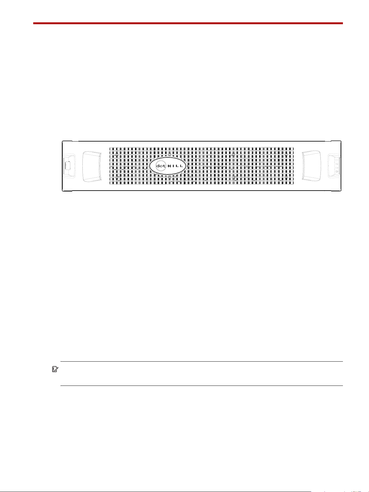
A LED descriptions
Front panel LEDs
AssuredSAN Ultra48 Series supports high-capacity 2U48 enclosures. The 2U48 chassis—configured with
48 2.5" small form factor (SFF) disks—is used as either a controller enclosure or expansion enclosure.
The 4144 2U48 48-drive enclosure is used for adding storage.
Enclosure bezel
Each AssuredSAN Ultra48 Series enclosure is equipped with a removable bezel designed to cover the
front panel during enclosure operation. The bezel used with the 2U48 chassis provides two debossed
pockets. It is equipped with an EMI (Electromagnetic Interface) shield to provide protection for the disks.
Figure 34 Front panel enclosure bezel: 48-drive enclosure (2U48)
Enclosure bezel attachment and removal
When you initially attach or remove the front panel enclosure bezel for the first time, refer to the
appropriate pictorials for your enclosure(s) from the list below, and follow the instructions provided.
• Front view of 48-drive enclosure (2U48): Figure 34
• Bezel alignment for 48-drive enclosure (2U48): Figure 35 on page 72
Enclosure bezel attachment
Orient the enclosure bezel to align its back side with the front face of the enclosure as shown in Figure 35
on page 72. Face the front of the enclosure, and while supporting the base of the bezel, position it such
that the mounting sleeves within the integrated ear caps align with the ball studs, and then gently push-fit
the bezel onto the ball studs to securely attach the bezel to the front of the enclosure.
Enclosure bezel removal
While facing the front of the enclosure, insert the index finger of each hand into the top of the respective
(left or right) pocket opening, and insert the middle finger of each hand into the bottom of the respective
opening, with thumbs on the bottom of the bezel face. Gently pull the top of the bezel while applying slight
inward pressure below, to release the bezel from the ball studs.
IMPORTANT: Refer to Figure 35 on page 72 when either attaching or removing the enclosure bezel. The
bezel should be installed while the enclosure is in operation.
Figure 36 on page 72 provides illustration details showing drawer access. Before accessing the drawer,
you may need to loosen the drawer stop thumbscrew located on the front of the drawer to unlock the
drawer from its locked position (see Opening and closing a drawer on page 24).
AssuredSAN Ultra48 Series Setup Guide 71
Page 72
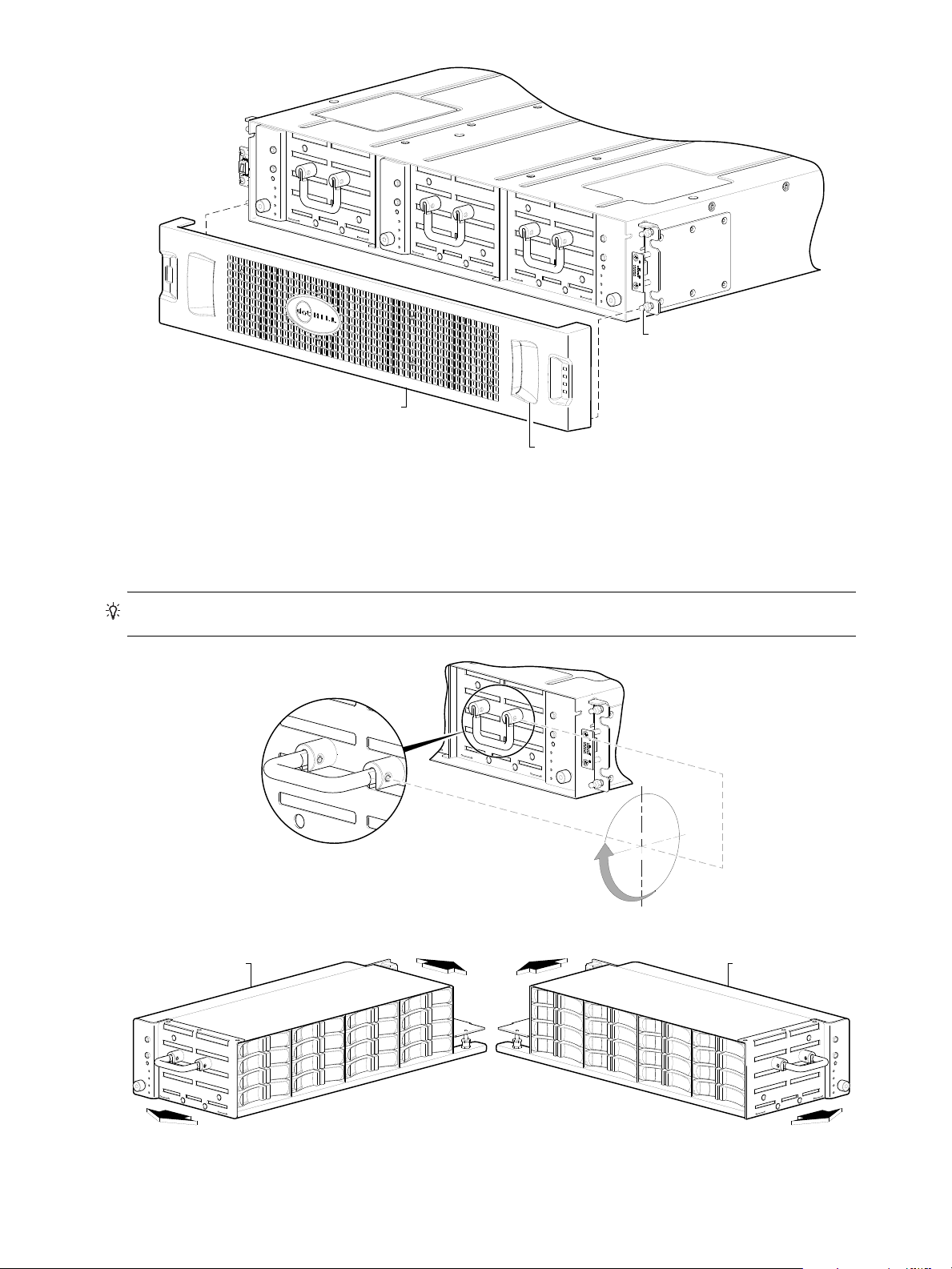
Figure 35 Partial assembly showing bezel alignment with 2U48 chassis
Ball stud on chassis ear
(typical 4 places)
Enclosure bezel sub-assembly
(Includes EMI shield for disks)
Pocket opening (typical 2 places)
90°
Revolve the handle 90° from its stowed position to
its pull-position before pulling the drawer outward.
Drawer travels inward and outward along the drawer slide.
Drawers 0 or 1 Drawer 2
Once you have removed the bezel, you can access the drawers. To open a drawer, you should first revolve
the pull-handle upwards by 90° to enable pulling the drawer outward for viewing disks. The handle can be
in the stowed position when pushing the drawer back into the enclosure along the drawer slide.
TIP: Revolve the drawer handle upwards by 90° before pulling the drawer outward along the slide.
Figure 36 Drawer detail showing handle rotation and drawer travel
72 LED descriptions
Page 73
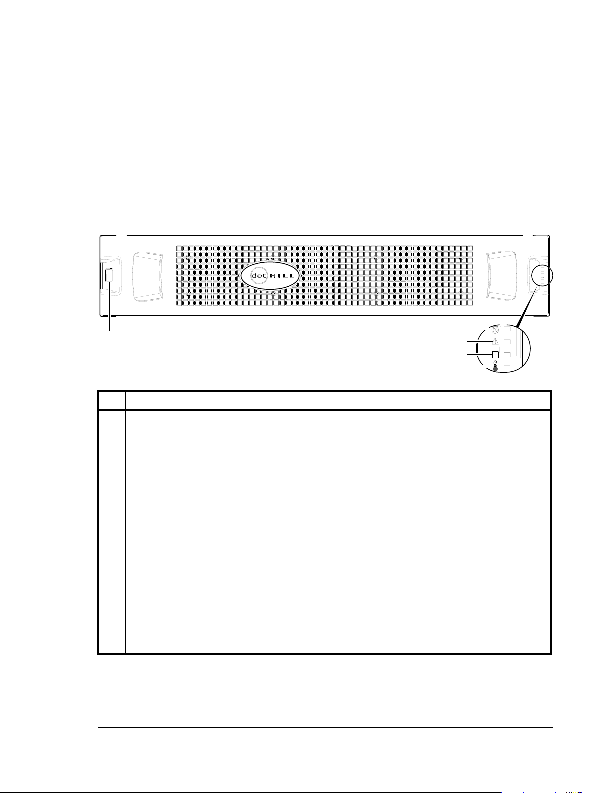
48-drive enclosure front panel LEDs
OK
2
3
4
5
Note: Remove this enclosure bezel to access drawers.
1
Enclosure front panel LEDs are described in two interrelated figure/table ensembles within this subsection:
• Figure 37: describes enclosure front panel LEDs (visible with the bezel installed).
• Figure 38 on page 74: describes drawer panel LEDs (visible with the bezel removed).
The disk module LED is described in another related figure/table ensemble within Disk drive LED:
• Figure 39 on page 75: describes the LED located on disk modules (visible with the bezel removed and
drawer(s) opened).
• Table 29 and Table 30 on page 76 describe additional disk LED behavior.
LEDs visible with enclosure bezel installed
The LEDs located on the chassis ears are described in Figure 37 and are visible with the enclosure bezel
installed.
LED Description Definition
1 Enclosure ID Green — On
Enables you to correlate the enclosure with logical views presented by
management software. Sequential enclosure ID numbering of controller
enclosures begins with the integer 0. The enclosure ID for an attached drive
enclosure is nonzero.
2 Unit Locator White blink — Enclosure is identified
Off — Normal operation
3 Fault/Service Required Amber — On
Enclosure-level fault condition exists. The event has been acknowledged but
the problem needs attention.
Off — No fault condition exists.
4 FRU OK Green — On
The enclosure is powered on with at least one power supply operating
normally.
Off — Both power supplies are off; the system is powered off.
5 Temperature Fault Green — On
The enclosure temperature is normal.
Amber — On
The enclosure temperature is above threshold.
Figure 37 LEDs: 2U48 enclosure front panel
NOTE: The enclosure front panel illustrations that follow assume that you have removed the enclosure
bezel to reveal underlying components.
AssuredSAN Ultra48 Series Setup Guide 73
Page 74
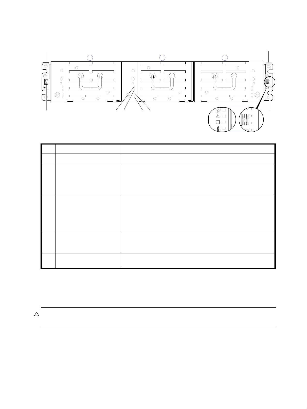
LEDs visible with enclosure bezel removed
1 20
31
4
Left ear
Right ear
Note: Integers atop drawers indicate drawer numbering sequence.
OK
(Silk screens on bezel)
1
2
5
The enclosure bezel is removed to reveal the underlying 2U48 enclosure front panel LEDs. The front panel
LEDs—including ear LEDs and drawer panel LEDs—are described in the table below the illustration.
LED Description Definition
1 Enclosure ear LEDs Enclosure ear LEDs (see Figure 37 on page 73).
2 FRU OK Green — On
The drawer is powered on with the power supply operating normally.
Green — blink
The drawer is initializing.
Off — The drawer is not OK.
3 Fault/Service Required Amber — On
Drawer-level fault condition exists. The event has been acknowledged but
the problem needs attention.
Amber — Blink
Hardware-controlled power-up.
Off — No fault condition exists.
4 OK to Remove Blue — On
The drawer is prepared for removal.
Off — The drawer is not prepared for removal.
5 Unit Locator White blink — Enclosure is identified
Off — Normal operation
Figure 38 LEDs: 2U48 drawer front panel
The enclosure bezel for this model provides the EMI protection for the SFF disk drive modules. The bezel
should be securely attached to the enclosure during operation (see Enclosure bezel attachment on page 71
and Figure 35 on page 72).
CAUTION: To ensure adequate EMI protection for the SFF disk drives, the enclosure bezel should be
properly installed while the enclosure is in operation.
74 LED descriptions
Page 75
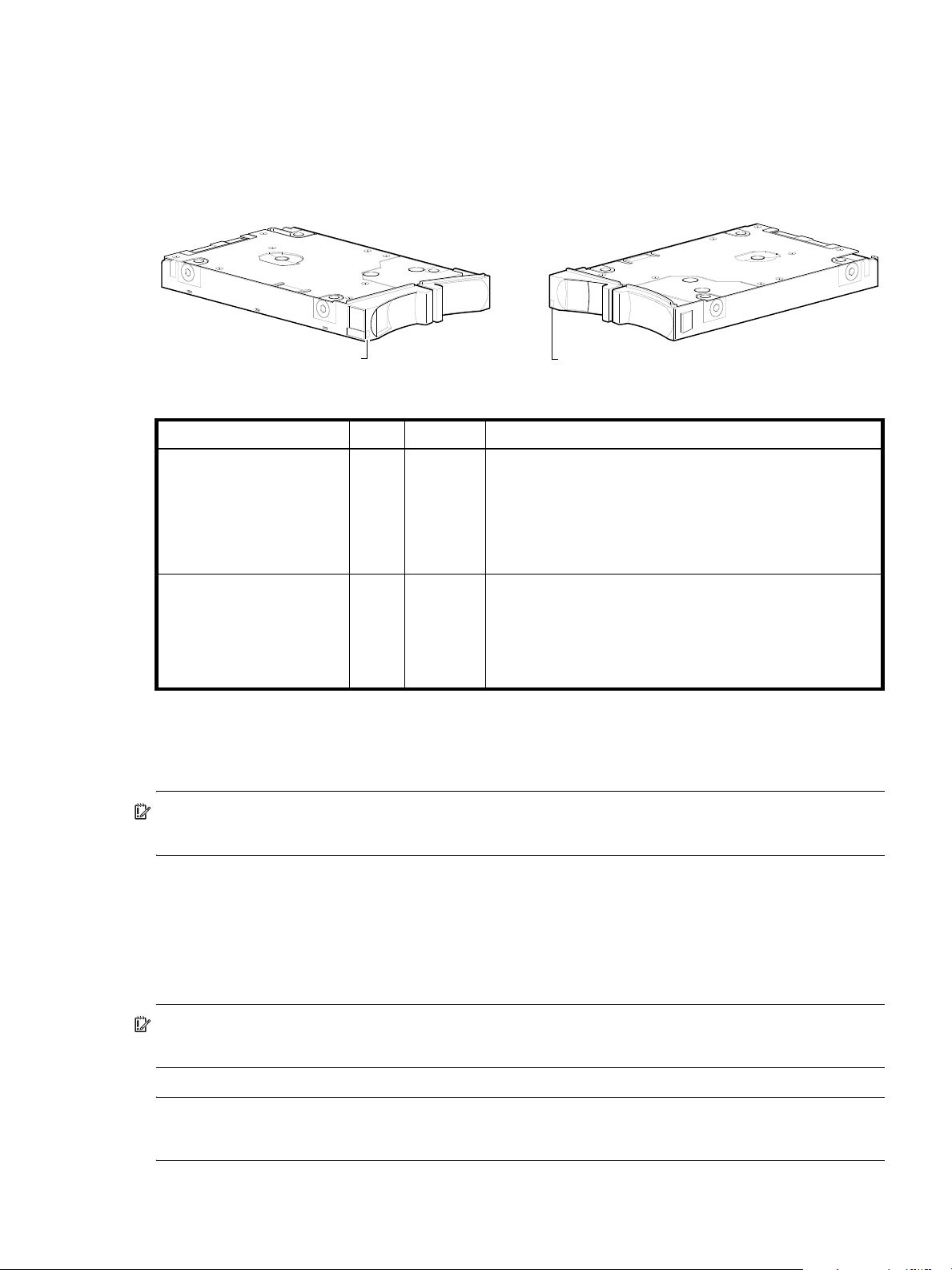
Disk drive LED
Disk aligned for Drawer 0 or 1
2.5" SFF disk drive module
(see table below for LED behaviors)
Bi-color LED Bi-color LED
Disk aligned for Drawer 2
You must remove the enclosure bezel to facilitate visual observation of the drawers containing disk drive
modules. To view disks in a drawer, you must open the drawer (see see Opening and closing a drawer on
page 24). Alternatively, you can use management interfaces to monitor disk LED behavior.
LED mode description Color State Definition
Removal/Identification/Fault Blue On
1Hz Blink
4Hz Blink
Off
Power/Activit y Green O n
Blink
Off
The disk drive is prepared for removal.
Physically identifies the disk drive module.
The disk has failed; experienced a fault; is a leftover; or the
vdisk that it is associated with is down or critical.
The disk drive is not powered on.
The disk drive module is operating normally.
The disk drive module is initializing; active and processing I/O;
performing a media scan; or the vdisk is initializing or
reconstructing.
The disk drive is not powered on.
Figure 39 LEDs: Disk drive modules
For information about disk drives supported in Ultra48 Series see SFF disk drive modules, see Disk drives
used in Ultra48 Series enclosures on page 17.
IMPORTANT: For instructions about accessing drawers and installing disk drive modules into them, see
Populating drawers on page 24.
For information about replacing a disk drive module in a Ultra48 Series controller enclosure or 4144 drive
enclosure, refer to the “Replacing a disk drive module” topic in the AssuredSAN Ultra48 Series FRU
Installation and Replacement Guide. Instructions are provided for replacing SFF disk drive modules therein.
For information about creating a vdisk with volumes, and mapping the volumes to hosts, see the
“Provisioning the system” topic within the AssuredSAN 4004 Series RAIDar User Guide.
IMPORTANT: For information about self-encrypting disk (SED) drives, see FDE considerations on page 27
and the RAIDar User Guide or online help.
NOTE: Additional information pertaining to disk drive LED behavior is provided in the supplementary
tables on the facing page.
AssuredSAN Ultra48 Series Setup Guide 75
Page 76
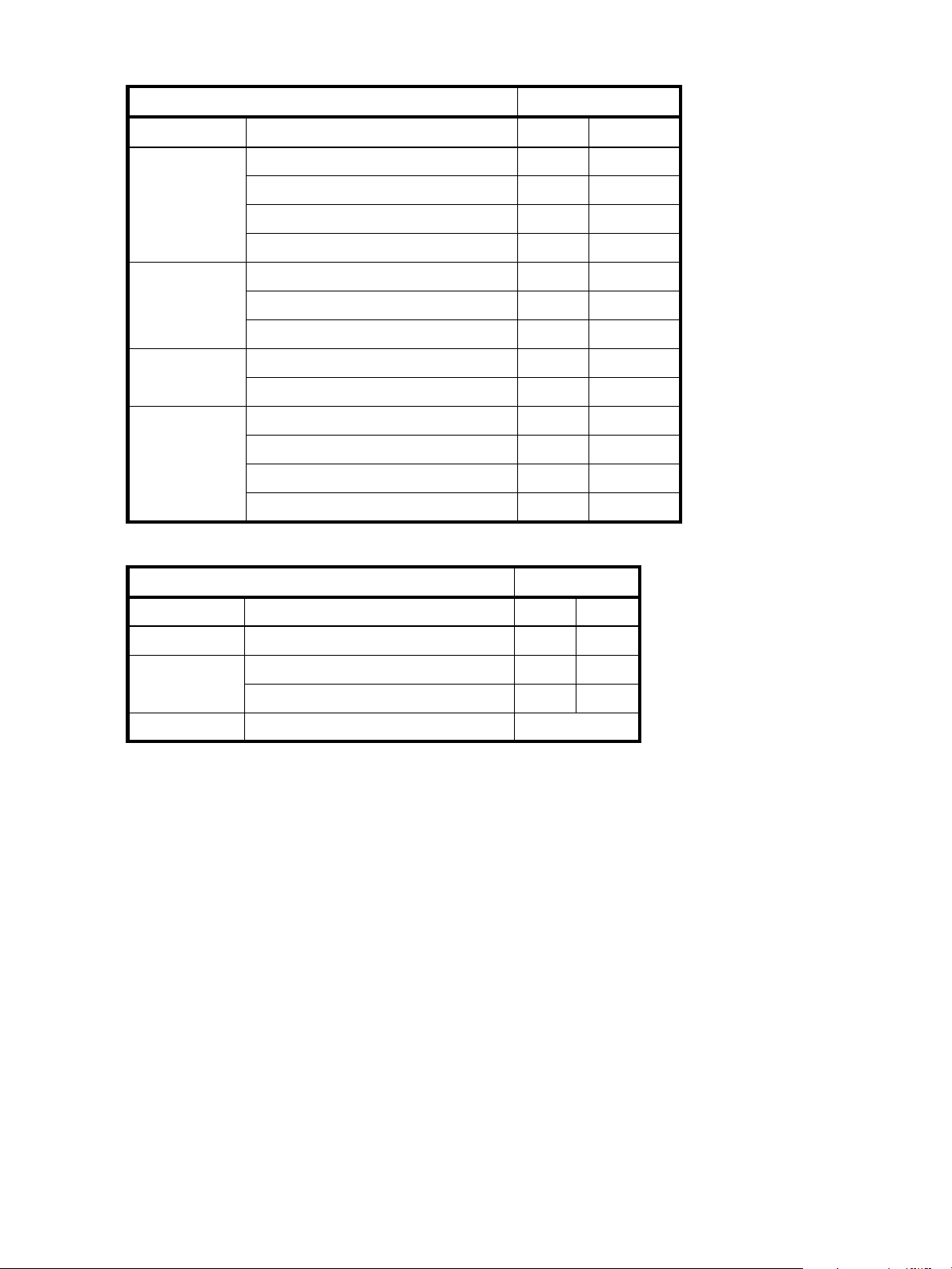
Table 29 LEDs: Disks in 2U48 enclosures
Disk drive module LED behavior SFF disk drive module
Description
Disk drive OK,
FTOL
Disk drive I/O Initializing Green Blink
Disk drive
leftover
Disk drive failed Fault or failure Blue Blink—4Hz
State Color Action
Off None None
On (operating normally) Green On
OK to remove Blue On
Identifying self—offline/online Blue Blink—1Hz
Active and processing I/O Green Blink
Performing a media scan Green Blink
Disk drive is a leftover Blue Blink—4Hz
Identifying a leftover Blue Blink—4Hz
Fault and remove disk drive Blue Blink—4Hz
Fault and identify disk drive Blue Blink—4Hz
Fault, identify, and remove disk drive Blue Blink—4Hz
Table 30 LEDs: Vdisks in 2U48 enclosures
Vdisk LED behavior SFF disks
Description State Color Action
FTOL On (operating normally) Green On
Vdisk activity Vdisk is reconstructing Green Blink
Vdisk is initializing Green Blink
Vdisk degraded Vdisk is critical/down
1
Individual disks will display fault LEDs
See note 1 below
76 LED descriptions
Page 77
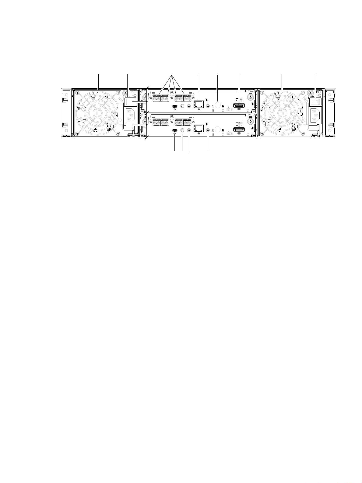
Controller enclosure — rear panel layout
CACHE
LINK
ACT
6Gb/s
CACHE
LINK
ACT
6Gb/s
CLI
CLI
PORT 2 PORT 3
SERVICE−1SERVICE−2
PORT 0 PORT 1
CLI
CLI
PORT 2 PORT 3
SERVICE−1SERVICE−2
PORT 0 PORT 1
159
10
12
6
11
1
4
4844 model is shown as a locator example
78
2
3
2
The diagram and table below display and identify important component items that comprise the rear panel
layout of an AssuredSAN Ultra48 Series controller enclosure. In Figure 40 below, a 4844 is shown as a
representative example. Diagrams and tables on the following pages describe rear panel LED behavior.
1 AC power supplies
2 AC power switch
3 Controller module A
4 Controller module B
5 CNC ports: used for host connection or replication
6 CLI port (USB - Type B)
8 Reserved for future use
9 Network port
10 Service port 1 (used by service personnel only)
11 Disabled button (used by engineering/test only)
(Stickers shown covering the openings)
12 SAS expansion port
7 Service port 2 (used by service personnel only)
Figure 40 Ultra48 Series controller enclosure: rear panel
A controller enclosure accommodates two AC power supply FRUs within the two power supply slots (see
two instances of callout No.1 above). The controller enclosure accommodates two controller module FRUs
of the same type within the I/O module (IOM) slots (see callouts No.3 and No.4 above).
The diagrams with tables that immediately follow provide descriptions for the different controller modules
and power supply modules that can be installed into the rear panel of an Ultra48 Series controller
enclosure. Showing controller modules and power supply modules separately from the enclosure enables
improved clarity in identifying the component items called out in the diagrams and described in the tables.
LED descriptions are also provided for optional drive enclosures supported by the Ultra48 Series controller
enclosures.
For information about replacing Ultra48 Series controller enclosure FRUs, refer to the appropriate FRU
replacement procedure in the AssuredSAN Ultra48 Series FRU Installation and Replacement Guide.
AssuredSAN Ultra48 Series Setup Guide 77
Page 78
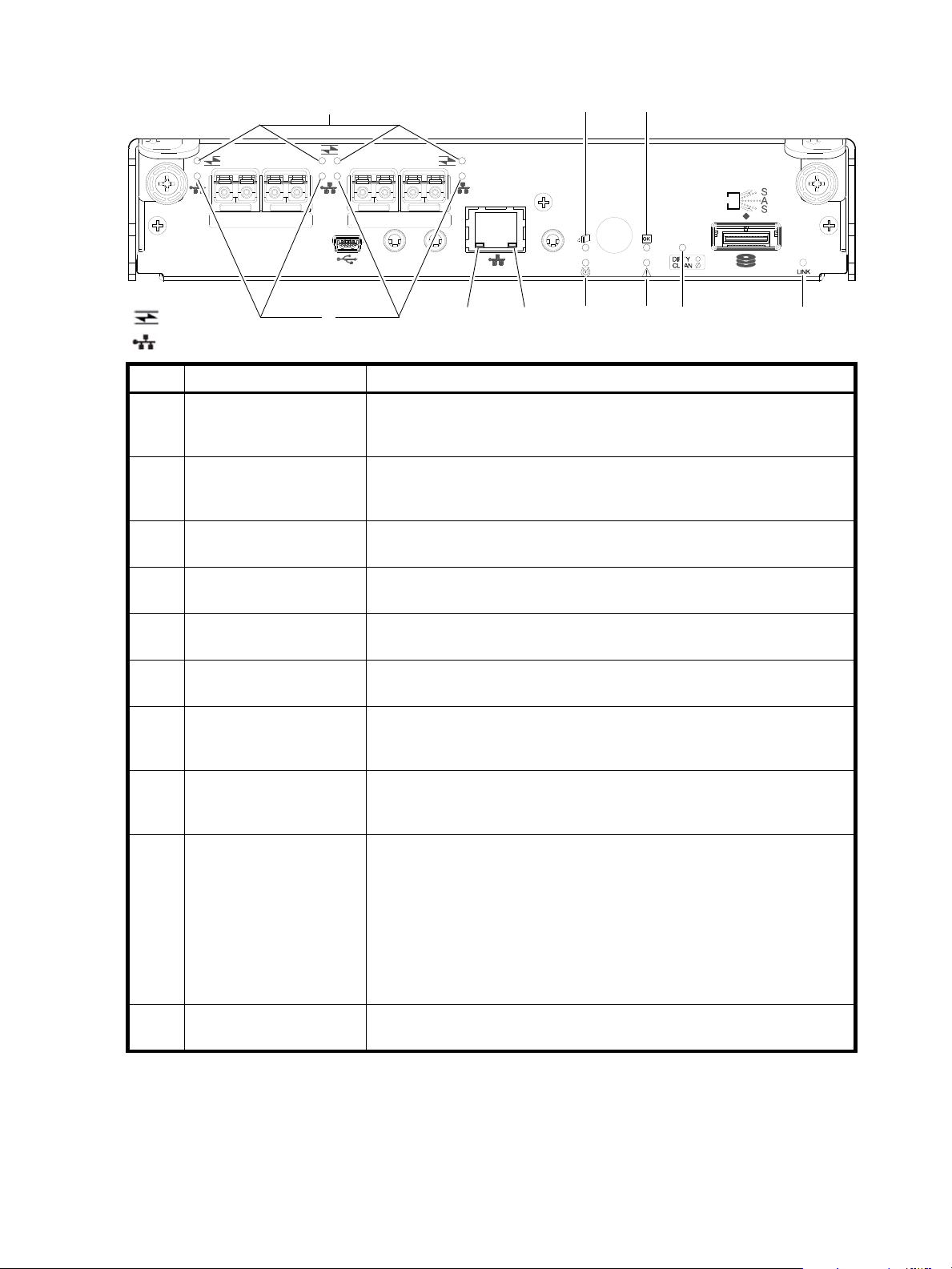
4844 CNC controller module — rear panel LEDs
CACHE
CLI
CLI
LINK
ACT
6Gb/s
SERVICE−1SERVICE−2
PORT 0 PORT 1 PORT 2 PORT 3
= FC LEDs
= iSCSI LEDs
157
23468910
LED Description Definition
2,3
1
Off — No link detected.
Green — The port is connected and the link is up.
Blinking green — The link has I/O or replication activity.
Off — No link detected.
Green — The port is connected and the link is up.
Blinking green — The link has I/O or replication activity.
1Host 4/8/16 Gb FC
Link Status/
Link Activity
2Host 10GbE iSCSI
Link Status/
Link Activity
3Network Port Link
Active Status
4
Off — The Ethernet link is not established, or the link is down.
Green — The Ethernet link is up (applies to all negotiated link speeds).
4 Network Port Link Speed4Off — Link is up at 10/100base-T negotiated speeds.
Amber — Link is up and negotiated at 1000base-T.
5 OK to Remove Off — The controller module is not prepared for removal.
Blue — The controller module is prepared for removal.
6 Unit Locator Off — Normal operation.
Blinking white — Physically identifies the controller module.
7 FRU OK Off — Controller module is not OK.
Blinking green — System is booting.
Green — Controller module is operating normally.
8 Fault/Service Required Amber — A fault has been detected or a service action is required.
Blinking amber — Hardware-controlled power-up or a cache flush or restore
error.
9 Cache Status Green — Cache is dirty (contains unwritten data) and operation is normal.
The unwritten information can be log or debug data that remains in the
cache, so a Green cache status LED does not, by itself, indicate that any user
data is at risk or that any action is necessary.
Off — In a working controller, cache is clean (contains no unwritten data).
This is an occasional condition that occurs while the system is booting.
Blinking green — A CompactFlash flush or cache self-refresh is in progress,
indicating cache activity.
See also Cache Status LED details on page 81.
10 Expansion Port Status Off — The port is empty or the link is down.
On — The port is connected and the link is up.
1
When in FC mode, the SFPs must be a qualified 8 Gb or 16 Gb fibre optic option. A 16 Gbit/s SFP can run at 16 Gbit/s, 8 Gbit/s,
4 Gbit/s, or auto-negotiate its link speed. An 8 Gbit/s SFP can run at 8 Gbit/s, 4 Gbit/s, or auto-negotiate its link speed.
2
When in 10GbE iSCSI mode, the SFPs must be a qualified 10GbE iSCSI optic option.
3
When powering up and booting, iSCSI LEDs will be on/blinking momentarily, then they will switch to the mode of operation.
4
When port is down, both LEDs are off.
Figure 41 LEDs: 4844 CNC controller module (FC and 10GbE SFPs)
78 LED descriptions
Page 79
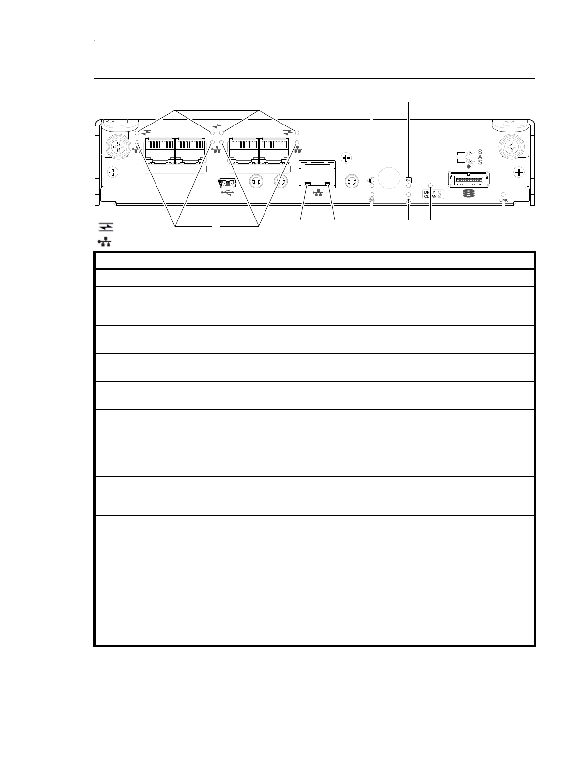
NOTE: For information about supported combinations of host interface protocols using CNC ports, see CNC
CACHE
CLI
CLI
LINK
ACT
6Gb/s
SERVICE−1SERVICE−2
PORT 0 PORT 1 PORT 2 PORT 3
= FC LEDs
157
23468910
= 1Gb iSCSI LEDs (all CNC ports use 1 Gb RJ-45 SFPs in this figure)
ports used for host connection on page 11 and the “Configuring host ports topic” in the RAIDar User Guide.
LED Description Definition
2,3
1
The FC SFP is not shown in this example (see Figure 41 on page 78).
Off — No link detected.
Green — The port is connected and the link is up.
Blinking green — The link has I/O or replication activity.
1 Not used in example
2Host 1 Gb iSCSI
Link Status/
Link Activity
3Network Port Link
Active Status
4
Off — The Ethernet link is not established, or the link is down.
Green — The Ethernet link is up (applies to all negotiated link speeds).
4 Network Port Link Speed4Off — Link is up at 10/100base-T negotiated speeds.
Amber — Link is up and negotiated at 1000base-T.
5 OK to Remove Off — The controller module is not prepared for removal.
Blue — The controller module is prepared for removal.
6 Unit Locator Off — Normal operation.
Blinking white — Physically identifies the controller module.
7 FRU OK Off — Controller module is not OK.
Blinking green — System is booting.
Green — Controller module is operating normally.
8 Fault/Service Required Amber — A fault has been detected or a service action is required.
Blinking amber — Hardware-controlled power-up or a cache flush or restore
error.
9 Cache Status Green — Cache is dirty (contains unwritten data) and operation is normal.
The unwritten information can be log or debug data that remains in the
cache, so a Green cache status LED does not, by itself, indicate that any user
data is at risk or that any action is necessary.
Off — In a working controller, cache is clean (contains no unwritten data).
This is an occasional condition that occurs while the system is booting.
Blinking green — A CompactFlash flush or cache self-refresh is in progress,
indicating cache activity.
See also Cache Status LED details on page 81.
10 Expansion Port Status Off — The port is empty or the link is down.
On — The port is connected and the link is up.
1
When in FC mode, the SFPs must be a qualified 8 Gb or 16 Gb fibre optic option. A 16 Gbit/s SFP can run at 16 Gbit/s, 8 Gbit/s,
4 Gbit/s, or auto-negotiate its link speed. An 8 Gbit/s SFP can run at 8 Gbit/s, 4 Gbit/s, or auto-negotiate its link speed.
2
When in 1 GbE iSCSI mode, the SFPs must be a qualified 1 GbE iSCSI optic option.
3
When powering up and booting, iSCSI LEDs will be on/blinking momentarily, then they will switch to the mode of operation.
4
When port is down, both LEDs are off.
Figure 42 LEDs: 4844 CNC controller module (1 Gb RJ-45 SFPs)
AssuredSAN Ultra48 Series Setup Guide 79
Page 80
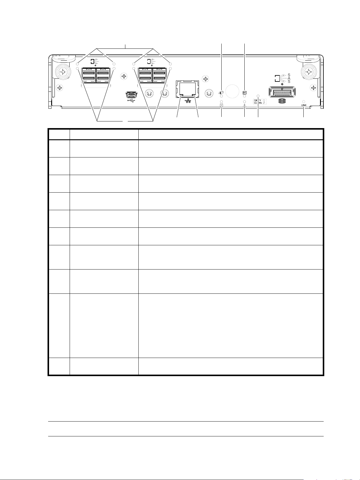
4544 SAS controller module—rear panel LEDs
CACHE
CLI
CLI
LINK
ACT
6Gb/s
SERVICE−1SERVICE−2
ACT
LINK
12Gb/s
S
S
A
ACT
LINK
SAS 0 SAS 1
ACT
LINK
12Gb/s
S
S
A
ACT
LINK
SAS 2 SAS 3
157
23468910
LED Description Definition
1- 3
1- 3
Off — No link detected.
Green — The port is connected and the link is up.
Off — The link is idle.
Blinking green — The link has I/O activity.
1Host 12 Gb SAS,
Link Status
2Host 12 Gb SAS
Link Activity
3Network Port Link
Active Status
4
4 Network Port Link Speed
Off — The Ethernet link is not established, or the link is down.
Green — The Ethernet link is up (applies to all negotiated link speeds).
4
Off — Link is up at 10/100base-T negotiated speeds.
Amber — Link is up and negotiated at 1000base-T.
5 OK to Remove Off — The controller module is not prepared for removal.
Blue — The controller module is prepared for removal.
6 Unit Locator Off — Normal operation.
Blinking white — Physically identifies the controller module.
7 FRU OK Off — Controller module is not OK.
Blinking green — System is booting.
Green — Controller module is operating normally.
8 Fault/Service Required Amber — A fault has been detected or a service action is required.
Blinking amber — Hardware-controlled power-up or a cache flush or restore
error.
9 Cache Status Green — Cache is dirty (contains unwritten data) and operation is normal.
The unwritten information can be log or debug data that remains in the
cache, so a Green cache status LED does not, by itself, indicate that any user
data is at risk or that any action is necessary.
Off — In a working controller, cache is clean (contains no unwritten data).
This is an occasional condition that occurs while the system is booting.
Blinking green — A CompactFlash flush or cache self-refresh is in progress,
indicating cache activity.
See also Cache Status LED details on page 81.
10 Expansion Port Status Off — The port is empty or the link is down.
1
Cables must be qualified HD mini-SAS host cable options.
2
Use a qualified SFF-8644 to SFF-8644 cable option when connecting the 4524/4534 controller to a 12 Gb SAS HBA.
3
Use a qualified SFF-8644 to SFF-8088 cable option when connecting the 4524/4534 controller to a 6 Gb SAS HBA.
4
When port is down, both LEDs are off.
Figure 43 LEDs: 4544 SAS controller module (HD mini-SAS)
80 LED descriptions
NOTE: Once a Link Status LED is lit, it remains so, even if the controller is shut down via RAIDar or CLI.
On — The port is connected and the link is up.
Page 81
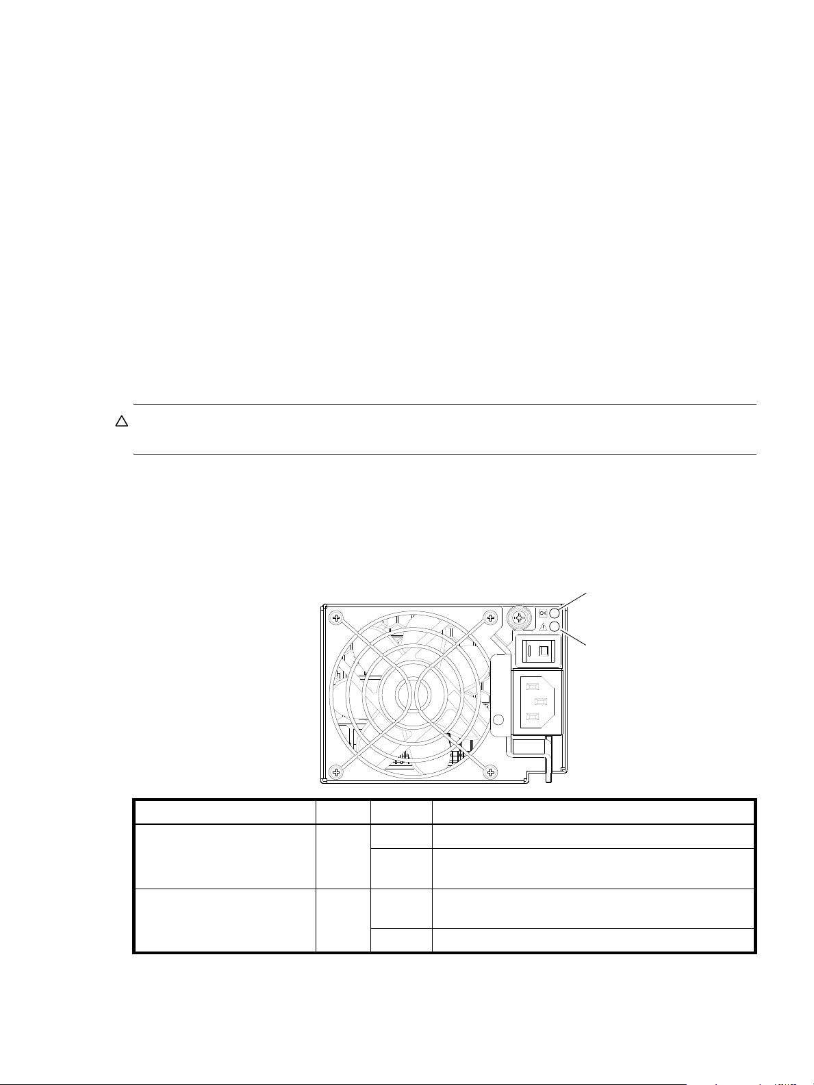
When a controller is shut down or otherwise rendered inactive—its Link Status LED remains illuminated—
1
2
falsely indicating that the controller can communicate with the host. Though a link exists between the host
and the chip on the controller, the controller is not communicating with the chip. To reset the LED, the
controller must be power-cycled (see Powering on/powering off
Cache Status LED details
If the LED is blinking evenly, a cache flush is in progress. When a controller module loses power and write
cache is dirty (contains data that has not been written to disk), the supercapacitor pack provides backup
power to flush (copy) data from write cache to CompactFlash memory. When cache flush is complete, the
cache transitions into self-refresh mode.
If the LED is blinking momentarily slowly, the cache is in a self-refresh mode. In self-refresh mode, if primary
power is restored before the backup power is depleted (3–30 minutes, depending on various factors), the
system boots, finds data preserved in cache, and writes it to disk. This means the system can be operational
within 30 seconds, and before the typical host I/O time-out of 60 seconds, at which point system failure
would cause host-application failure. If primary power is restored after the backup power is depleted, the
system boots and restores data to cache from CompactFlash, which can take about 90 seconds. The cache
flush and self-refresh mechanism is an important data protection feature; essentially four copies of user data
are preserved: one in controller cache and one in CompactFlash of each controller. The Cache Status LED
illuminates solid green during the boot-up process. This behavior indicates the cache is logging all POSTs,
which will be flushed to the CompactFlash the next time the controller shuts down.
CAUTION: If the Cache Status LED illuminates solid green—and you wish to shut-down the controller—do
so from the user interface, so unwritten data can be flushed to CompactFlash.
on page 31).
Power supply LEDs
Power redundancy is achieved through two independent load-sharing power supplies. In the event of a
power supply failure, or the failure of the power source, the storage system can operate continuously on a
single power supply. Greater redundancy can be achieved by connecting the power supplies to separate
circuits. AC power supplies have a power switch. Power supplies are used by controller and drive
enclosures.
LED No./Description Color State Definition
1 — Input Source Power Good Green On Power is on and input voltage is normal.
Off Power is off, or input voltage is below the minimum
threshold.
2 — Voltage/Fan Fault/Service
Required
Amber On Output voltage is out of range, or a fan is operating below
the minimum required RPM.
Off Output voltage is normal.
Figure 44 LEDs: Power supply units — rear panel
AssuredSAN Ultra48 Series Setup Guide 81
Page 82
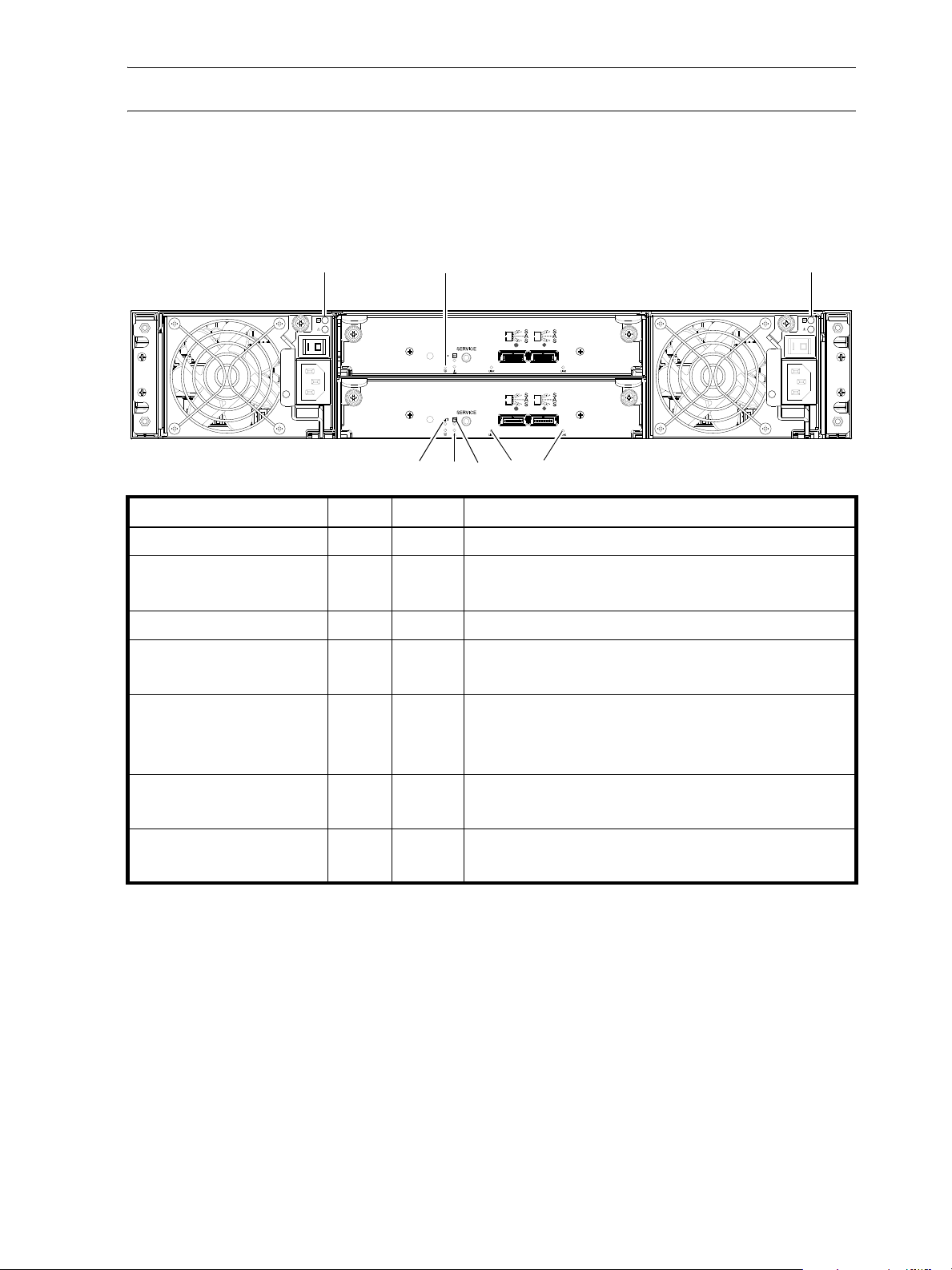
NOTE: See Powering on/powering off on page 31 for information on power-cycling enclosures.
IN OUT
IN OUT
6Gb/s 6Gb/s
6Gb/s 6Gb/s
12
63 54 7
1
4144 drive enclosure rear panel LEDs
The rear panel layout of the 4144 drive enclosure is shown below. Using mini-SAS (SFF-8088) external
connectors, this drive enclosure supports a 6-Gbps data rate for backend SAS expansion. See Powering
on/powering off
LED No./Description Color State Definition
1 — Power Supply — — See Power supply LEDs on page 81.
on page 31 for more information.
2 — Unit Locator White Off
Blink
Normal operation.
Physically identifies the expansion module.
3 — OK to Remove Blue Off Not implemented.
4 — Fault/Service Required Amber On
Blink
5 — FRU OK Green On
Off
Blink
6 — SAS In Port Status Green On
Off
7 — SAS Out Port Status Green On
Off
A fault is detected or a service action is required.
Hardware-controlled power-up.
Expansion module is operating normally.
Expansion module is not OK.
System is booting.
Port is connected and the link is up.
Port is empty or link is down.
Port is connected and the link is up.
Port is empty or link is down.
Figure 45 LEDs: 4144 drive enclosure — rear panel
82 LED descriptions
Page 83
B Environmental requirements and specifications
Safety requirements
Install the system in accordance with the local safety codes and regulations at the facility site. Follow all
cautions and instructions marked on the equipment.
IMPORTANT: Also see the hard copy AssuredSAN Product Regulatory Compliance and Safety document
(included in your product ship kit).
Alternatively, you can access the document online. See Dot Hill’s customer resource center (CRC) web site
for additional information: http://crc.dothill.com
Select AssuredSAN & R/Evolution Products > 4004 Series to download the PRC&S document.
Site requirements and guidelines
The following sections provide requirements and guidelines that you must address when preparing your site
for the installation.
When selecting an installation site for the system, choose a location not subject to excessive heat, direct
sunlight, dust, or chemical exposure. These conditions greatly reduce the system’s longevity and might void
your warranty.
.
.
Site wiring and AC power requirements
The following are required for all installations using AC power supplies:
.
Table 31 Power requirements - AC Input
Measurement Rating
Input power requirements 100-240 VAC, 50/60 Hz
Maximum input power 640 W maximum continuous
Heat dissipation 2,245 BTUs/hour
• All AC mains and supply conductors to power distribution boxes for the rack-mounted system must be
enclosed in a metal conduit or raceway when specified by local, national, or other applicable
government codes and regulations.
• Ensure that the voltage and frequency of your power source match the voltage and frequency inscribed
on the equipment’s electrical rating label.
• To ensure redundancy, provide two separate power sources for the enclosures. These power sources
must be independent of each other, and each must be controlled by a separate circuit breaker at the
power distribution point.
• The system requires voltages within minimum fluctuation. The customer-supplied facilities’ voltage must
maintain a voltage with not more than
suitable surge protection.
• Site wiring must include an earth ground connection to the AC power source. The supply conductors
and power distribution boxes (or equivalent metal enclosure) must be grounded at both ends.
• Power circuits and associated circuit breakers must provide sufficient power and overload protection. To
prevent possible damage to the AC power distribution boxes and other components in the rack, use an
external, independent power source that is isolated from large switching loads (such as air conditioning
motors, elevator motors, and factory loads).
± 5 percent fluctuation. The customer facilities must also provide
AssuredSAN Ultra48 Series Setup Guide 83
Page 84

Weight and placement guidelines
Refer to Physical requirements on page 85 for detailed size and weight specifications.
• The weight of an enclosure depends on the number and type of modules installed.
• Use two people to lift an enclosure. You can reduce the weight by removing the power supply modules
and enclosure drawers.
• Do not place enclosures in a vertical position. Always install and operate the enclosures in a horizontal
(level) orientation.
• When installing enclosures in a rack, make sure that any surfaces over which you might move the rack
can support the weight. To prevent accidents when moving equipment, especially on sloped loading
docks and up ramps to raised floors, ensure you have a sufficient number of helpers. Remove obstacles
such as cables and other objects from the floor.
• To prevent the rack from tipping, and to minimize personnel injury in the event of a seismic occurrence,
securely anchor the rack to a wall or other rigid structure that is attached to both the floor and to the
ceiling of the room.
Electrical guidelines
• These enclosures work with single-phase power systems having an earth ground connection. To reduce
the risk of electric shock, do not plug an enclosure into any other type of power system. Contact your
facilities manager or a qualified electrician if you are not sure what type of power is supplied to your
building.
• Enclosures are shipped with a grounding-type (three-wire) power cord. To reduce the risk of electric
shock, always plug the cord into a grounded power outlet.
• Do not use household extension cords with the enclosures. Not all power cords have the same current
ratings. Household extension cords do not have overload protection and are not meant for use with
computer systems.
Ventilation requirements
Refer to Environmental requirements on page 87 for detailed environmental requirements.
• Do not block or cover ventilation openings at the front and rear of an enclosure. Never place an
enclosure near a radiator or heating vent. Failure to follow these guidelines can cause overheating and
affect the reliability and warranty of your enclosure.
• Leave a minimum of 15.2 cm (6 inches) at the front and back of each enclosure to ensure adequate
airflow for cooling. No cooling clearance is required on the sides, top, or bottom of enclosures.
• Leave enough space in front and in back of an enclosure to allow access to enclosure components for
servicing. Removing a component requires a clearance of at least 38.1 cm (15 inches) in front of and
behind the enclosure.
Cabling requirements
• Keep power and interface cables clear of foot traffic. Route cables in locations that protect the cables
from damage.
• Route interface cables away from motors and other sources of magnetic or radio frequency
interference.
• Stay within the cable length limitations.
Management host requirements
A local management host with at least one mini-USB connection is recommended for the initial installation
and configuration of a controller enclosure. After you configure one or both of the controller modules with
an IP address, you then use a remote management host on an Ethernet network to manage and monitor.
NOTE: Connections to this device must be made with shielded cables – grounded at both ends – with
metallic RFI/EMI connector hoods, in order to maintain compliance with FCC Rules and Regulations.
84 Environmental requirements and specifications
Page 85

Physical requirements
The floor space at the installation site must be strong enough to support the combined weight of the rack,
controller enclosures, drive enclosures, and any additional equipment. The site also requires sufficient
space for installation, operation, and servicing of the enclosures, together with sufficient ventilation to allow
a free flow of air to all enclosures.
Figure 46 and Table 32 on page 86 show enclosure dimensions and weights. Enclosure designators are
described below. Enclosure weights assume the following configuration characteristics:
• 2U48 enclosure (high-capacity with SFF disks)
• “2U48” denotes the 2.5" 48-drive enclosure (with controller or expansion modules)
• The 2U48 chassis includes three installed drawer slots that must be populated with disks and
possibly AMS inserts if applicable, after the enclosure is installed into the rack. The table in this
section assumes each drive slot contains a disk drive module.
• 2U24 enclosure (comparative enclosure dimensions are provided for reference):
• “2U24” denotes the 2.5" 24-drive enclosure (with controller or expansion modules)
• The 2U24 chassis is equipped with a disk in each disk drive slot
NOTE: For 2U24 product information, see the AssuredSAN 4004 Series Setup Guide.
• 2U12 enclosure (comparative enclosure dimensions are provided for reference):
• “2U12” denotes the 3.5" 12-drive enclosure (with controller or expansion modules)
• The 2U12 chassis is equipped with a disk in each disk drive slot
NOTE: For 2U24 product information, see the AssuredSAN 4004 Series Setup Guide.
• Two controller modules or two expansion modules per enclosure
• Two power supply modules per enclosure
NOTE: The following table provides comparative measurements for the 2U48, 2U24, and 2U12
enclosures supported by AssuredSAN 4004 Series.
This document describes the AssuredSAN Ultra48 Series controller enclosures. Measurements for the 2U24
and 2U12 enclosures are included within the table portion of Figure 46 on page 86 simply for ease of
comparison. For information about the 2U24 and 2U12 enclosures, see the AssuredSAN 4004 Series
Setup Guide.
AssuredSAN Ultra48 Series Setup Guide 85
Page 86
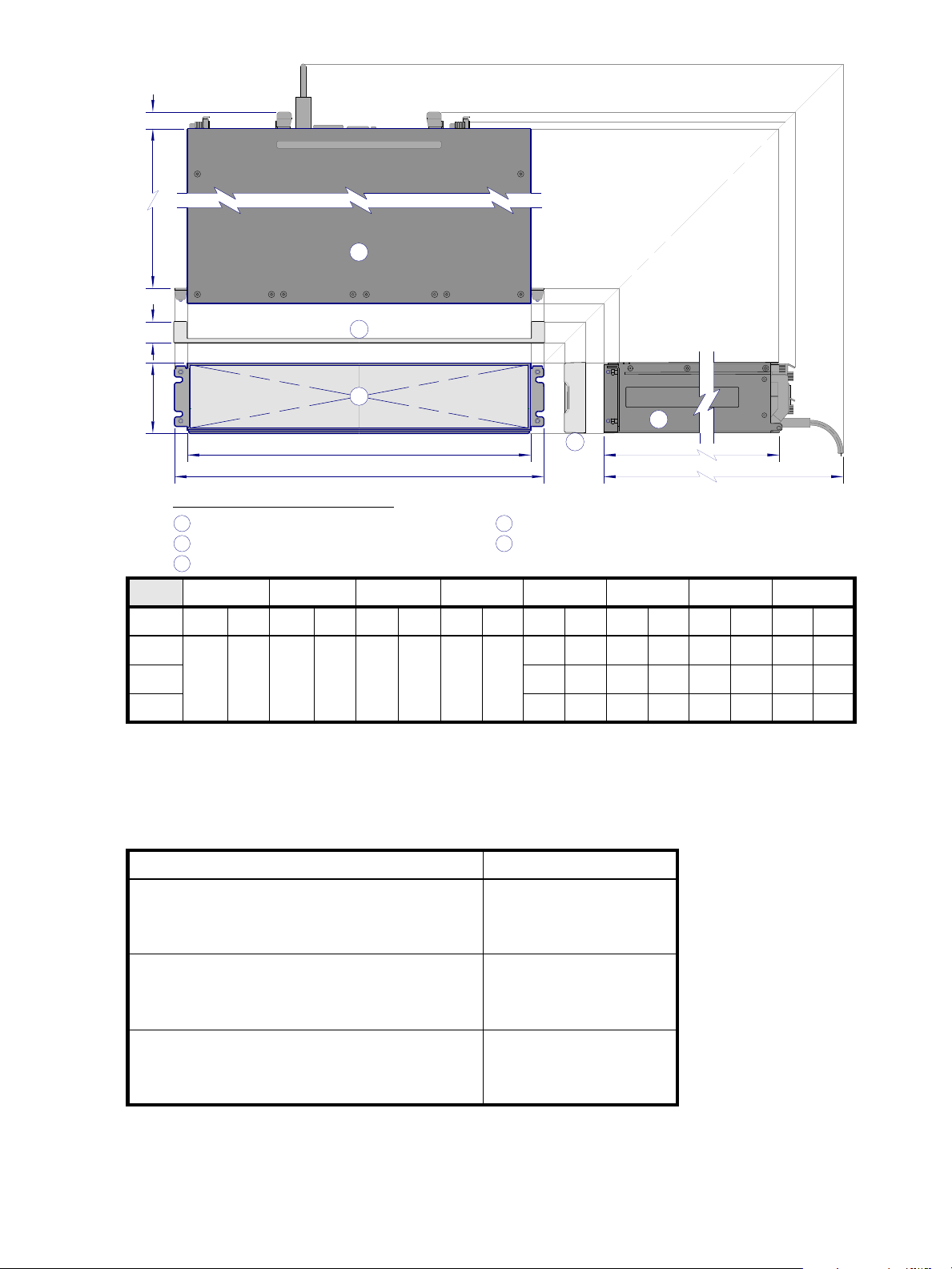
ABCDEFGH
A
C
BE
DF
G
H
1
1
2
3
4
5
Key for generic enclosure diagram:
−
Enclosure front view without bezel or disks
2
−
Enclosure top view (section removed)
3
−
Enclosure side view (section removed)
4
−
Enclosure bezel top view (reference only)
5
−
Enclosure bezel side view (reference only)
Critical−fit dimensions (see table)
A−H:
Note: For clarity, only key view projection lines are shown.
45° orthographic bisector
Form cm in cm in cm in cm in cm in cm in cm in cm in
1
2U48
2
2U24
2U12
.
.1The 2U48 enclosure uses 2.5" SFF disks. Remove the enclosure bezel and open the drawer to view disk drive module LEDs.
2
The 2U24 enclosure uses 2.5" SFF disks. Remove the enclosure bezel to view disk drive module LEDs.
3
The 2U12 enclosure uses 3.5" LFF disks. Remove the enclosure bezel to view disk drive module LEDs.
44.7 17.6 8.9 3.5 47.9 18.9 2.5 .98
3
72.4
47.6
52.7
28.5
18 . 7
20.5
3.0
3.0
3.0
1. 2
1. 2
1. 2
74 .4
51. 8
54.9
29.3
20.4
21. 6
81. 5
57.9
59.9
Figure 46 Rackmount enclosure dimensions
..
Table 32 Rackmount controller enclosure weights
Specifications Rackmount
32.1
22.8
23.6
SFF controller enclosure (2U24)
• Chassis with FRUs (no disks)
• Chassis with FRUs (including disks)
1- 3
1- 4
LFF controller enclosure (2U12)
• Chassis with FRUs (no disks)
• Chassis with FRUs (including disks)
1- 3
1- 4
High-capacity controller enclosure (2U48)
• Chassis with FRUs (no disks)
• Chassis with FRUs (including disks)
1
Weights shown are nominal, and subject to variances.
2
Rail kits add between 2.8 kg (6.2 lb) and 3.4 kg (7.4 lb) to the aggregate enclosure weight.
3
Weights may vary due to different power supplies, IOMs, and differing calibrations between scales.
4
Weights may vary due to actual number and type of disk drives (SAS or SSD) and air management modules installed.
1- 3
1- 4
86 Environmental requirements and specifications
8.6 kg (19.0 lb) [chassis]
17.4 kg (38.4 lb)
23 . 4 k g ( 51. 6 l b )
9.3 kg (20.6 lb) [chassis]
18 .1 kg (4 0 . 0 l b )
27.7 kg (61.0 lb)
12.7 kg (28.0 lb) [chassis]
23.1 kg (50.9 lb)
34.0 kg (74.9 lb)
Page 87
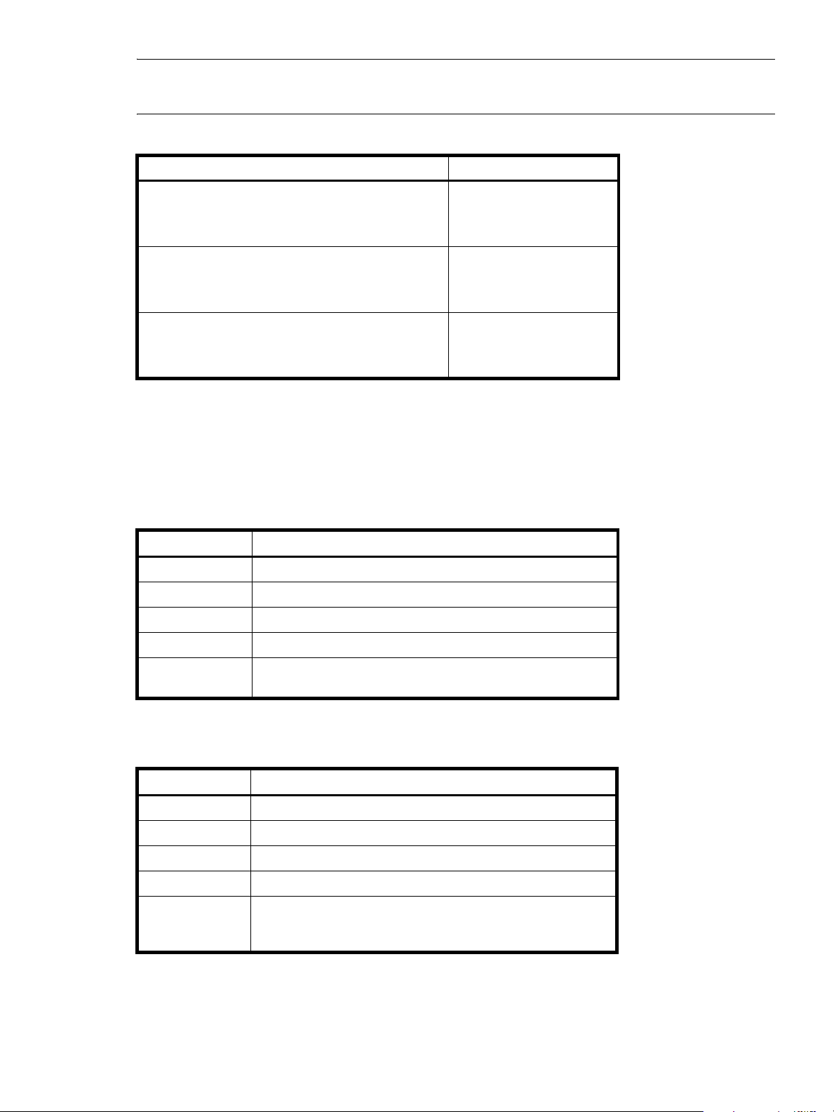
NOTE:
The table below provides comparative information about optional drive enclosures used with 4004
Series controller enclosures. Ultra48 Series controller enclosures optionally use 4144 drive enclosures
Table 33 Rackmount compatible drive enclosure weights (ordered separately)
Specifications Rackmount
.
4124 (SFF 2.5" 24-drive enclosure)
• Chassis with FRUs (no disks)
1- 3
• Chassis with FRUs (including disks)
4134 ( L F F 3 . 5 " 12 - d r iv e e n c lo s u r e )
• Chassis with FRUs (no disks)
1- 3
• Chassis with FRUs (including disks)
4144 (high-capacity 48-drive enclosure (SFF 2.5" disks)
• Chassis with FRUs (no disks)
1- 3
• Chassis with FRUs (including disks)
1
Weights shown are nominal, and subject to variances.
2
Rail kits add between 2.8 kg (6.2 lb) and 3.4 kg (7.4 lb) to the aggregate enclosure weight.
3
Weights may vary due to different power supplies and differing calibrations between scales.
4
Weights may vary due to actual number and type of disk drives (SAS or SSD) and air management modules installed.
Environmental requirements
Table 34 Operating environmental specifications
Specification Range
Altitude To 3,000 meters (9,843 feet )
Temperature
1
5ºC to 35ºC (41ºF to 95ºF)
1- 4
1- 4
1- 4
8.6 kg (19.0 lb) [chassis]
16.2 kg (35.8 lb)
22.2 kg (49.0 lb)
8.5 kg (18.8 lb) [chassis]
16.1 kg (35.6 lb)
25.6 kg (56.6 lb)
12.7 kg (28.0 lb) [chassis]
20.3 kg (44.8 lb)
31.2 kg (68.8 lb)
Humidity 10% to 90% RH up to 35ºC (95ºF) non-condensing
Shock 3.0 g, 11 ms, ½ sine pulses, X, Y, Z
2
Vibration (Shaped-spectrum)
5 Hz to 500 Hz, 0.14 G
1
Data center environmental conditions are required.
2
Drawers must be closed and secured.
total X, Y, Z
rms
Table 35 Non-operating environmental specifications
Specification Range
Altitude To 12,000 meters (39,370 feet)
Temperature -5ºC to 70ºC (23ºF to 158ºF)
Humidity Up to 93% RH @ 40ºC (104ºF) non-condensing
Shock 10.0 g, 11 ms, ½ sine pulses, X, Y, Z
Vibration (Shaped-spectrum)
2.8 Hz to 365.4 Hz, 0.852 G
2.8 Hz to 365.4 Hz, 1.222 G
total (horizontal)
rms
total (vertical)
rms
AssuredSAN Ultra48 Series Setup Guide 87
Page 88

Electrical requirements
Site wiring and power requirements
Each enclosure has two power supply modules for redundancy. If full redundancy is required, use a
separate power source for each module. The AC power supply unit in each power supply module is
auto-ranging and is automatically configured to an input voltage range from 88–264 VAC with an input
frequency of 47–63 Hz. The power supply modules meet standard voltage requirements for both U.S. and
international operation. The power supply modules use standard industrial wiring with line-to-neutral or
line-to-line power connections.
Power cable requirements
Each enclosure ships with two power cables designed for use with the enclosure power supply module. AC
power cords ship with enclosures equipped with AC power supply modules. Each power cable connects
one of the power supply modules to an independent, external power source. To ensure power redundancy,
connect the two power cables to two separate circuits; for example, to one commercial circuit and one
uninterruptible power source (UPS).
88 Environmental requirements and specifications
Page 89

C Electrostatic discharge
Preventing electrostatic discharge
To prevent damaging the system, be aware of the precautions you need to follow when setting up the
system or handling parts. A discharge of static electricity from a finger or other conductor may damage
system boards or other static-sensitive devices. This type of damage may reduce the life expectancy of the
device.
To prevent electrostatic damage:
• Avoid hand contact by transporting and storing products in static-safe containers.
• Keep electrostatic-sensitive parts in their containers until they arrive at static-protected workstations.
• Place parts in a static-protected area before removing them from their containers.
• Avoid touching pins, leads, or circuitry.
• Always be properly grounded when touching a static-sensitive component or assembly.
Grounding methods to prevent electrostatic discharge
Several methods are used for grounding. Use one or more of the following methods when handling or
installing electrostatic-sensitive parts:
• Use a wrist strap connected by a ground cord to a grounded workstation or computer chassis. Wrist
straps are flexible straps with a minimum of 1 megohm (± 10 percent) resistance in the ground cords.
To provide proper ground, wear the strap snug against the skin.
• Use heel straps, toe straps or boot straps at standing workstations. Wear the straps on both feet when
standing on conductive floors or dissipating floor mats.
• Use conductive field service tools.
• Use a portable field service kit with a folding static-dissipating work mat.
If you do not have any of the suggested equipment for proper grounding, have an authorized reseller
install the part. For more information about static electricity or assistance with product installation, contact
an authorized reseller.
AssuredSAN Ultra48 Series Setup Guide 89
Page 90

90 Electrostatic discharge
Page 91
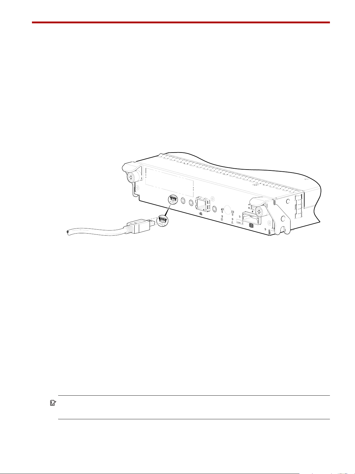
D USB device connection
CACHE
LINK
DIRTY
LINK
ACT
CLI
CLI
Host Interface
Not Shown
SERVICE−2
SERVICE−1
6Gb/s
Connect USB cable to CLI
port on controller face plate
Rear panel USB ports
AssuredSAN Ultra48 Series controllers contain two different USB (universal serial bus) management
interfaces: a Host interface and a Device interface. Both interfaces pertain to the Management Controller
(MC). The Device interface is accessed via a port on the controller module face plate. The Host interface
(USB Type A)—reserved for future use—is accessible from the midplane-facing end of the controller module
(see Figure 10 on page 22), and its discussion is deferred.
This appendix describes the port labeled CLI (USB Type B), which enables direct connection between a
management computer and the controller, using the command-line interface and appropriate cable (see
Figure 47).
USB CLI port
AssuredSAN Ultra48 Series controllers feature a USB CLI port used to cable directly to the controller and
initially set IP addresses, or perform other configuration tasks. The USB CLI port employs a mini-USB Type B
form factor, and requires a specific cable and additional support, so that a server or other computer
running a Linux or Windows operating system can recognize the controller enclosure as a connected
device. Without this support, the computer might not recognize that a new device is connected, or might
not be able to communicate with it.
For Linux computers, no new driver files are needed, but a Linux configuration file must be created or
modified (see Linux on page 93). For Windows computers a special device driver file,
be downloaded from a web site, and installed on the computer that will be cabled directly to the
controller’s CLI port (see Microsoft Windows on page 92).
Emulated serial port
Once attached to the controller module, the management computer should detect a new USB device.
Using the Emulated Serial Port interface, the Ultra48 Series controller presents a single serial port using a
customer vendor ID and product ID. Effective presentation of the emulated serial port assumes the
management computer previously had terminal emulator installed (see Supported host applications). Serial
port configuration is unnecessary.
IMPORTANT: Certain operating systems require a device driver or special mode of operation to enable
proper functioning of the USB CLI port (see Device driver/special operation mode).
Figure 47 USB device connection — CLI port
gserial.inf, must
AssuredSAN Ultra48 Series Setup Guide 91
Page 92
Supported host applications
Ultra48 Series controllers support the following applications to facilitate connection.
Table 36 Supported terminal emulator applications
Application Operating system
HyperTerminal and TeraTerm Microsoft Windows (all versions)
Minicom Linux (all versions)
Solaris
HP-UX
Command-line Interface
Once the management computer detects connection to the USB-capable device, the Management
Controller awaits input of characters from the host computer via the command-line. To see the
command-line prompt, you must press Enter. The MC provides direct access to the CLI.
NOTE: Directly cabling to the CLI port is an out-of-band connection, because it communicates outside of
the data paths used to transfer information from a computer or network to the controller enclosure.
Device driver/special operation mode
Certain operating systems require a device driver or special mode of operation. Product and vendor
identification information required for such setup is provided below.
Table 37 USB vendor and product identification codes
USB Identification code type Code
USB Vendor ID 0x210c
USB Product ID 0xa4a7
Microsoft Windows
Microsoft Windows operating systems provide a USB serial port driver. However, the USB driver requires
details for connecting to AssuredSAN Ultra48 Series controller enclosures. Dot Hill provides a device driver
for use in the Windows environment. The USB device driver and installation instructions are available via
download.
Obtaining the software download
1. Verify that the management computer has Internet access.
2. See Dot Hill’s customer resource center (CRC) web site http://crc.dothill.com
a. Select AssuredSAN & R/Evolution Products > Software Downloads.
Peruse the list of articles for an entry pertaining to USB device driver.
b. Click on the underscored article title to view its content.
The screen reformats to display article content together with a supporting pane to the right of the
article. This pane provides optional actions and attachments.
c. Click on the zip file icon under Attachments in the right pane adjacent to the article.
The File Download dialog displays.
d. From the File Download dialog, save the zip file locally to the management computer.
e. Follow the instructions accompanying the device driver within the zip file to install the USB device
driver.
.
92 USB device connection
Page 93

Linux
Although Linux operating systems do not require installation of a device driver, certain parameters must be
provided during driver loading to enable recognition of the AssuredSAN Ultra48 Series controller
enclosures.
Setting parameters for the device driver
1. Enter the following command:
modprobe usbserial vendor=0x210c product=0xa4a7 use_acm=1
2. Press Enter to execute the command.
The Linux device driver is loaded with the parameters required to recognize the controllers.
NOTE: Optionally, this information can be incorporated into the /etc/modules.conf file.
Using the CLI port and cable—known issues on Windows
When using the CLI port and cable for setting network port IP addresses, be aware of the following known
issues on Microsoft Windows platforms.
Problem
On Windows operating systems, the USB CLI port may encounter issues preventing the terminal emulator
from reconnecting to storage after the Management Controller (MC) restarts or the USB cable is unplugged
and reconnected.
Workaround
Follow these steps when using the mini-USB cable and USB Type B CLI port to communicate out-of-band
between the host and controller module for setting network port IP addresses.
To create a new connection or open an existing connection (HyperTerminal):
1. From the Windows Control Panel, select Device Manager.
2. Connect using the USB COM port and Detect Carrier Loss option.
a. Select Connect To > Connect using: > pick a COM port from the list.
b. Select the Detect Carrier Loss check box.
The Device Manager page should show “Ports (COM & LPT)” with an entry entitled “Disk Array USB
Port (COMn)”—where n is your system’s COM port number.
3. Set network port IP addresses using the CLI (see procedure on page 45).
To restore a hung connection when the MC is restarted (any supported terminal emulator):
1. If the connection hangs, disconnect and quit the terminal emulator program.
a. Using Device Manager, locate the COMn port assigned to the Disk Array Port.
b. Right-click on the hung Disk Array USB Port (COMn), and select Disable.
c. Wait for the port to disable.
2. Right-click on the previously hung—now disabled—Disk Array USB Port (COMn), and select Enable.
3. Start the terminal emulator and connect to the COM port.
4. Set network port IP addresses using the CLI (see procedure on page 45).
AssuredSAN Ultra48 Series Setup Guide 93
Page 94

94 USB device connection
Page 95
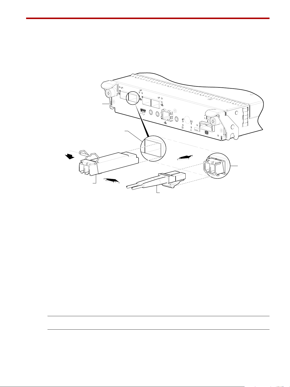
E SFP option for CNC ports
PORT 1
CACHE
LINK
DIRTY
LINK
ACT
CLI
CLI
SERVICE−2
SERVICE−1
PORT 0
PORT 1
PO
RT 2
PO
RT 3
PORT 1
6Gb/s
Installed SFP
(actuator closed)
Target CNC port
Align SFP for installation
(plug removed/actuator open)
Controller module face plate
Fibre-optic interface cable
Locate the SFP transceivers
Locate the qualified SFP option for your CNC controller module within your product ship kit. The SFP
transceiver (SFP) should look similar to the generic SFP shown in the figure below.
provided in Electrostatic discharge when installing an SFP.
Follow the guidelines
Install an SFP transceiver
For each target CNC port, perform the following procedure to install an SFP. Refer to the figure above
when performing the steps.
1. Orient the SFP as shown above, and align it for insertion into the target CNC port.
2. If the SFP has a plug, remove it before installing the transceiver. Retain the plug.
3. Flip the actuator open as shown in the figure (near the left detail view).
4. Slide the SFP into the target CNC port until it locks into place.
5. Flip the actuator down, as indicated by the down-arrow next to the open actuator in the figure.
6. When ready to attach to the host, obtain and connect a qualified fibre-optic interface cable into the
NOTE: To remove an SFP module, perform the above steps in reverse order.
Verify component operation
Figure 48 Install a qualified SFP option
The SFP should be positioned such that the actuator pivot-hinge is on top.
The actuator on your SFP option may look slightly different than the one shown, and it may not open to
a sweep greater than 90° (as shown in the figure).
The installed SFP should look similar to the position shown in the right detail view.
duplex jack at the end of the SFP connector.
View the CNC port Link Status/Link Activity LED on the controller module face plate. A green LED indicates that
the port is connected and the link is up (see LED descriptions for information about controller module LEDs).
AssuredSAN Ultra48 Series Setup Guide 95
Page 96

96 SFP option for CNC ports
Page 97

Index
Numerics
2U12
3.5" 12-drive enclosure
2U24
2.5" 24-drive enclosure
2U48
2.5" 48-drive enclosure
85
85
85
A
accessing
CLI (Command-line Interface)
RAIDar (web-based management GUI)
AssuredRemote
licensed replication feature
audience
12
46
40
B
bezel
2U48 enclosure
71
C
cables
FCC compliance statement
shielded
cabling
cable routing requirements
connecting controller and drive enclosures
considerations
direct attach configurations
switch attach configurations
cache
post-write
read-ahead
clearance requirements
service
ventilation
CNC ports
change port mode
locate and install SFPs
SFP transceivers
Command-line Interface
using to set controller IP addresses
CompactFlash
card location
transporting
components
2U48 enclosure front panel
4144 rear panel
4544 rear panel
40, 84
33
21
21
84
84
48
33
22
60
20
12 Gb SAS ports
CLI (reserved for future use)
CLI port (USB)
expansion port
20
20
40, 84
84
35
38
95
45
15
20
20
51
28
network port
service port 1
service port 2
4844 rear panel
CLI (reserved for future use)
CLI port (USB)
CNC ports (1 Gb iSCSI)
CNC ports (FC/10GbE)
expansion port
network port
service port 1
service port 2
Power Supply Unit (PSU)
AC
18
connecting
controller enclosures to hosts
to remote management hosts
connections
test
31
verify
31
console requirement
controller enclosures
connecting to hosts
connecting to remote management hosts
controller modules
4-port 1 Gb iSCSI (CNC)
4-port 10GbE iSCSI (CNC)
4-port 12 Gb SAS
4-port 8/16 Gb FC (CNC)
conventions
document
20
20
20
19
19
19
19
19
19
19
19
33
40
84
33
11
11
11
11
13
D
DHCP
obtaining IP addresses
server
45
direct attach configurations
disk drive
LEDs
general
specific states
document
conventions
prerequisite knowledge
related documentation
75
13
45
33
76
12
12
E
electrostatic discharge
grounding methods
precautions
enclosure
cabling
IDs, correcting
89
28
89
55
40
AssuredSAN Ultra48 Series Setup Guide 97
Page 98

initial configuration 23
input frequency requirement
input voltage requirement
installation checklist
site requirements
troubleshooting
weight
86, 87
Ethernet cables
requirements
85
55
40
88
23
F
faults
isolating
a host-side connection
expansion port connection fault
methodology
53
61
H
host interface ports
FC (8/16 Gb)
FC host interface protocol
loop topology
point-to-point protocol
iSCSI (10GbE)
iSCSI (1Gb)
iSCSI host interface protocol
mutual CHAP
SAS (12Gb)
SAS host interface protocol
hosts
defined
optional software
stopping I/O
system requirements
humidity non-operating range
humidity operating range
34
34
34
34
35
34, 35
35
35
33
33
56
33
87
87
I
IDs, correcting for enclosure 55
Installing a license
permanent
temporary
IP addresses
setting using DHCP
setting using the CLI
51
51
45
45
L
LEDs
2U48 front panel
Enclosure ID
Fault/Service Required
FRU OK
Temperature Fault
Unit Locator
4144 face plate
Fault/Service Required
FRU OK
OK to Remove
73, 74
73, 74
73, 74
73, 74
73, 74
82
82
82
88
63
SAS In Port Status
SAS Out Port Status
Unit Locator
Disk
Power/Activity
Removal/ID/Fault
enclosure rear panel
4544
12 Gb Host Link Activity
12 Gb Host Link Status
Cache Status
Expansion Port Status
Fault/Service Required
FRU OK
Network Port Link Active
Network Port Link Speed
OK to Remove
Unit Locator
4844
10GbE iSCSI Host Link Status/Link Activity
1Gb iSCSI Host Link Status/Link Activity
Cache Status
Expansion Port Status
Fault/Service Required
FC Host Link Status/Link Activity
FRU OK
Network Port Link Active
Network Port Link Speed
OK to Remove
Unit Locator
Power Supply Unit (PSU)
AC
Ultra48 Series controller enclosure rear panel
using to diagnose fault conditions
local management host requirement
80
78, 79
81
82
82
82
75
75
80
80
80
80
80
80
80
80
80
78, 79
78, 79
78, 79
78
78, 79
78, 79
78, 79
78, 79
56
84
M
MPIO DSM
native Microsoft installation
see related documentation
33
33
N
non-operating ranges, environmental 87
O
operating ranges, environmental 87
optional software
33
P
physical requirements 85
power cord requirements
power cycle
power off
power supply
AC power requirements
site wiring requirements
prerequisite knowledge
32
88
83
83
12
78
79
77
98 Index
Page 99

R
RAIDar
web-based storage management interface
regulatory compliance
notices
shielded cables
see related document
related documentation
remote management
requirements
cabling
clearance
Ethernet cables
host system
physical
ventilation
RFI/EMI connector hoods
84
84
85
84
40, 84
83
12
40
40
33
40, 84
S
safety precautions 83
sensors
locating
power supply
temperature
voltage
SFP transceivers
installing
locating
supported options
verifying operation
shock non-operating range
shock operating range
site planning
local management host requirement
physical requirements
safety precautions
storage system setup
configuring
getting started
provisioning
replicating
supercapacitor pack
switch attach configurations
68
68
68
69
95
95
33
95
87
87
85
83
51
51
51
51
22
38
84
51
U
Unified LUN Presentation 33
USB device connection
Command-line Interface (CLI)
device driver
emulated serial port
rear panel USB ports
supported host applications
vendor and product ID codes
92
91
91
92
92
92
V
ventilation requirements 84
vibration non-operating range
vibration operating range
87
87
W
warnings
temperature
voltage
web site
Dot Hill Systems Customer Resource Center 12, 21, 55
67
67
T
temperature non-operating range 87
temperature operating range
troubleshooting
controller failure, single controller configuration
correcting enclosure IDs
enclosure does not initialize
expansion port connection fault
host-side connection fault
using event notification
using RAIDar
using system LEDs
using the CLI
53
53
54, 56
54
87
55
55
63
61
54
60
AssuredSAN Ultra48 Series Setup Guide 99
Page 100

100 Index
 Loading...