


WQXM-PG WI-Q™ GATEWAY
SETUP AND USER GUIDE
Wireless Intelligence
That Stands Alone


CREDITS |COPYRIGHT
Credits/Copyright
Copyright ©2019 dormakaba USA Inc. All rights reserved.
Information in this document is subject to change without notice
and does not represent a commitment on the part of dormakaba
USA Inc. The software described in this document are furnished
under a license agreement or nondisclosure agreement.
This publication is intended to be an accurate description and set
of instructions pertaining to its subject matter. However, as with
any publication of this complexity, errors or omissions are pos-
sible. Please call dormakaba USA Inc. at (800) 392-5209 if you
see any errors or have any questions. No part of this manual and/
or databases may be reproduced or transmitted in any form or
by any means, electronic or mechanical, including photocopying,
recording, or information storage and retrieval systems, for any
purpose, without the express written permission of dormakaba
USA Inc.
Written and designed at dormakaba USA Inc.
6161 East 75th Street
Indianapolis, IN 46250
T91416/Rev A November 2019
This document is distributed as is, without warranty of any kind,
either express or implied, respecting the contents of this book,
including but not limited to implied warranties for the publication’s
quality, performance, merchantability, or tness for any particular
purpose. Neither dormakaba USA Inc., nor its dealers or distribu-
tors shall be liable to the user or any other person or entity with
respect to any liability, loss, or damage caused or alleged to be
caused directly or indirectly by this publication.
The Mercury LP4502, Wi-Q Technology and BEST are trademarks
of dormakaba USA Inc.
WQXM-PG Wi-Q™ Gateway Setup and User Guide | 3

DOCUMENT DISCLAIMERS
FCC/IC Certication
FCC/IC Certication
CAUTION: Please keep the PG antenna 20cm away from
people to ensure that FCC RF exposure compliance requirements are not exceeded.
THIS DEVICE COMPLIES WITH PART 15 OF THE FCC RULES.
Operation is subject to the following two conditions:
1. This device may not cause harmful interference, and
2. This device must accept any interference received, including interference that may cause undesired operation.
This equipment has been tested and found to comply with the lim-
its for Class B Digital Device, pursuant to Part 15 of the FCC Rules.
These limits are designed to provide reasonable protection against
harmful interference in a residential installation. This equipment
generates and can radiate radio frequency energy and, if not
installed and used in accordance with the instructions, may cause
harmful interference to radio communications. However, there is
no guarantee that interference will not occur in a particular instal-
lation. If this equipment does cause harmful interference to radio
or television reception, which can be determined by turning the
equipment o and on, you can try to correct the interference by
taking one or more of the following measures:
• Reorient or relocate the receiving antenna.
• Increase the separation between the equipment and receiver.
• Connect the equipment into an outlet on a circuit dierent from
that to which the receiver is connected.
• Consult the dealer or an experienced radio/TV technician for
help.
THIS DEVICE COMPLIES WITH INDUSTRY CANADA LICENSE-EXEMPT RSS STANDARD(S).
Operation is subject to the following two conditions:
1. This device may not cause interference, and
2. This device must accept any interference, including any
interference that may cause undesired operation of the
device.
This Class [B] digital apparatus meets all requirements of the Ca-
nadian Interference-Causing Equipment Regulations.
CET APPAREIL EST CONFORME À LA NORME RSS INDUSTRIE
CANADA EXEMPT DE LICENSE.
Son fonctionnement est soumis aux deux conditions suivantes:
1. Cet appareil ne doit pas provoquer d’interférences et
2. Cet appareil doit accepter toute interférence, y compris les
interferences pouvant causer un mauvais fonctionnement
du dispositif.
Cet appareil numérique de la classe [B] respecte toutes les exi-
gences du Réglement sur le matériel brouilleur du Canada.
4 | WQXM-PG Wi-Q™ Gateway Setup and User Guide

DOCUMENT DISCLAIMERS
FCC/IC Certication
Approved antennas are listed below, and antennas not included in
this list are strictly prohibited for use with these devices.
Approved Antennas
Conguration Description Antenna Part number
Gateway with rubber duck
antennas
Gateway with Ceiling Mount
Omni-directional antenna
Gateway with Interior/Exterior
Wall mount directional antenna
Gateway with Exterior omnidirectional mast mount antenna
WARNING: Changes or modications not expressly ap-
proved by dormakaba could void the user’s authority to
operate the equipment.
Pulse W1030W
PCTEL (Maxrad) MC2400PTMSMA
Mobile Mark (Comtelco) CMTB36247V
Mobile Mark (Comtelco)
CMTBS2400XL3
WQXM-PG Wi-Q™ Gateway Setup and User Guide | 5
dormakaba TECHNICAL SUPPORT
Address
dormakaba USA Inc.
6161 East 75th Street
Indianapolis, IN 46250
Web Page
www.bestaccess.com
Phone
1-800-392-5209
6 | WQXM-PG Wi-Q™ Gateway Setup and User Guide

TABLE OF CONTENTS
1 System Overview ...................................................................................8
1.1. Mercury LP4502 and Wi-Q Components ............................................... 8
2 Setup Checklist ...................................................................................... 9
3 Hardware Installation ............................................................................ 10
3.1 Hardware Overview ........................................................................ 10
3.1.1 LP4502 Controller Board ............................................................ 11
3.1.2 Gateways ................................................................................ 11
3.1.3 Wireless Controllers .................................................................. 11
3.1.4 Wireless Access Controllers ........................................................ 12
3.1.5 Antenna Types and Applications ................................................. 12
3.2 Installing System Hardware ............................................................. 13
3.2.1 What is needed to install Wi-Q hardware ..................................... 13
3.2.2 Develop a Site Plan (Task 1) ...................................................... 14
3.2.2.1 Site Survey ........................................................................... 21
3.2.2.2 Plotting the Plan .................................................................... 16
3.2.2.3 Device Identication .............................................................. 16
3.2.2.4 Interference .......................................................................... 16
3.2.2.5 Extended Range .................................................................... 16
3.2.3 Position Gateways (Task 2) ........................................................ 17
3.2.3.1 Antenna Types ...................................................................... 17
3.2.3.2 Power Supply ........................................................................ 17
3.2.3.3 Troubleshooting ..................................................................... 18
WQXM-PG Wi-Q™ Gateway Setup and User Guide | 7

TABLE OF CONTENTS
3.2.3.4 Next Steps ............................................................................ 19
3.2.4 Install Gateways (Task 3) .............................................................. 19
3.2.4.1 Connecting the Gateway and Verifying Operation ........................ 20
3.2.5 Congure Gateways (Task 4) ......................................................... 21
3.2.5.1 Access the Gateway’s Wireless Network ..................................... 21
3.2.5.2 Congure the WQXM-PG Gateway ............................................. 23
3.2.5.2.1 Login Screen .................................................................... 23
3.2.5.2.2 Manage Prole .................................................................. 23
3.2.5.3 SURVEY MODE ....................................................................... 25
3.2.5.3.1 Using the WQXM-PG Gateway for a Stand-Alone Site Survey ... 25
3.2.5.4 Gateway Status Window .......................................................... 27
3.2.5.4.1 Details ........................................................................................ 28
3.2.5.5 GATEWAY MENU .............................................................................. 31
3.2.5.5.1 Assigning an IP Address ................................................................. 32
3.2.5.6 INTERFACE MENU ........................................................................... 36
3.2.5.6 1 Enable Mercury Mode .................................................................... 36
3.2.5.6.2 Update the IP Conguration for the LP4502 Mercury Board ................. 39
3.2.5.6.3 Adding Sign-On Credentials to the WQXM-PG (Gateway) ................... 39
3.2.5.6.4 Sign On Wi-Q Controllers to the WQXM-PG ...................................... 42
3.2.5.6 Conguring the Mercury Panel for use with the WQXM-PG .................... 43
3.2.5.6 .1 Logging into the Mercury Board UI (User Interface) .......................... 43
3.2.5.6.2 Updating/Creating Users & Passwords .............................................. 44
8 | WQXM-PG Wi-Q™ Gateway Setup and User Guide

TABLE OF CONTENTS
3.2.5.6.3 Load SSL Certicates into the Mercury panel .................................... 45
3.2.6 Install Wireless Access Controllers (Task 5) ............................................ 47
3.2.6.1 Installation ..................................................................................... 48
3.2.6.2 Wireless Access Control Wiring .......................................................... 48
3.2.6.3 Resetting the WAC ........................................................................... 49
3.2.7 Install Wireless Door Controllers (Task 6) .............................................. 50
Before Beginning ........................................................................................ 50
Check Controller Operation .......................................................................... 51
Proximity Card Check .................................................................................. 51
Magnetic Card Check .................................................................................. 51
Keypad Check ............................................................................................ 51
Troubleshooting WDC and Omnilock locks ...................................................... 53
Troubleshooting the WAC\SDC ...................................................................... 53
3.2.8 Sign-On Wi-Q Controllers (Task 7) ........................................................ 55
Keypad Method .......................................................................................... 55
Magnetic Card Method ................................................................................. 55
Proximity Card Method ................................................................................ 55
3.2.8.1 Verify Sign-On Success..................................................................... 56
WDC 56
WAC 56
Omnilock ................................................................................................... 56
3.2.8.1 Verify Signal Strength and Packet Ratio Using Survey Mode ................... 57
WQXM-PG Wi-Q™ Gateway Setup and User Guide | 9

TABLE OF CONTENTS
Portal Signal Strength ................................................................................. 58
Reader Signal Strength ............................................................................... 58
Packet Transfer Ratio .................................................................................. 58
10 | WQXM-PG Wi-Q™ Gateway Setup and User Guide

TABLE OF CONTENTS
WQXM-PG Wi-Q™ Gateway Setup and User Guide | 11

1 SYSTEM OVERVIEW

1 SYSTEM OVERVIEW
This manual is the complete guide to the
integration of BEST Wi-Q wireless hard-
1.1 MERCURY LP4502 AND WI-Q COMPONENTS
1. ACS–Access Control Software
ware with the Mercury panel and the Access Control System. It provides detailed
steps for installing hardware and conguring the Mercury LP4502 for use with Wi-Q
gateways and controllers.
SYSTEM OVERVIEW
The information in this guide is presented in a linear manner;
however, tasks to install hardware and congure the system for
the rst time do not necessarily progress in a linear manner. There
is a Set Up Checklist in chapter 2 with step-by-step instructions to
walk through the initial setup and conguration tasks in a logical
sequence.
Figure 1 Mercury LP4502 and Wi-Q Components
Portal
Gateway
MERCURY
ACS
LP4502
LAN/WAN
Wireless
Door
Controller
2. Optional Mercury LP4502 ACS Interface Board
The Mercury LP4502 Access Control panel interface board can
communicate with up to 32 Wi-Q-Gateways with up to 128
Wi-Q controllers. This interface board is used for 3rd party
integration into Access Control Software.
3. WQXM-PG Portal Gateway
The Portal Gateway is a wireless device connected to the Host
computer through a secure IP address, similar to the way the
computer is connected to the Internet. It transfers data signals
from Wireless Controllers to and from the Host computer. The
Gateway recognizes all Wireless Controllers within its antenna
range. One Gateway can control as many as 64 Wireless Controllers in a system.
4. Wireless Door Controller
The Wireless Controller is equipped with Wi-Q Technology that
controls user access at the door. The basic conguration is
battery operated, with either keypad or card reading capability
and an internal antenna that communicates with the Gateway.
The Wireless Controller grants user requests according to how
they are congured in the Access Control Software.
WQXM-PG Wi-Q™ Gateway Setup and User Guide | 13

2 SETUP CHECKLIST

2 SETUP CHECKLIST
The Mercury Access Panel and Wi-Q hardware is set up in seven basic tasks. Com-
SETUP CHECKLIST
Note: System setup does not proceed in a linear manner. It may
be required to skip around in the process.
pleting these tasks will assist in getting
the system up and running as quickly and
eciently as possible. Some tasks are performed at the Host computer and some at
the segment site. It is appropriate to perform some tasks concurrently. For example, someone may prepare the computer
and install the software concurrently with
site plan development and hardware installation. However, the software must be
installed and Gateways ‘online’ before the
controllers can be signed in.
Task 1: Develop a Site Plan
See Page (20)
Task 2: Position Gateways
See Page (22)
Task 3: Install Gateways
See page (25)
Task 4: Congure Gateways
See page (26)
Task 5: Install Wireless Access Controllers
See page (42)
Task 6: Install Wireless Door Hardware
See page (44)
Task 7: Sign on Wi-Q Controllers
See page (47)
WQXM-PG Wi-Q™ Gateway Setup and User Guide | 15

3 HARDWARE INSTALLATION

3 HARDWARE INSTALLATION
Battery Pack
3 HARDWARE INSTALLATION
The Mercury LP4502 access panel locates
the Wi-Q portals on the local network and
integrates wireless hardware into your existing Access Control System.
HARDWARE INSTALLATION
existing Prox/Wiegand, RQE, door strike, and door monitor switch
congurations (B). Conguration types are briey described in the
following paragraphs. Full installation instructions are provided in
the following sections.
Note: Once Wi-Q controllers are installed, sign them on to the
WQXM-PG. Therefore, it is appropriate to install and congure the
Mercury before or concurrent with hardware installation. For more
information, see “Sign on Wi-Q Controller (Task 7)” on page 47.
3.1 HARDWARE OVERVIEW
Below is a block diagram showing various congurations. The
Mercury LP4502 interface panel supports all Wi-Q Technology
Wireless Controllers via the WQXM-PG Gateways (A); and
Figure 2 Hardware Overview
Secure
Socket
Host
Ethernet
10/100 BASE T
802.11g or Other
Comm. Carrier
LAN/WAN
Mercury LP4502
Up to 64 Wireless Devices
Per Portal Gateway
(configured in
increments of 16)
Portal
Gateway
Portal
Gateway
3.1.1 LP4502 Controller Board
The Mercury LP4502 Access Control panel interface board can
communicate with up to 32 Wi-Q-Gateways with up to 128 Wi-Q
controllers. This interface board is used for 3rd party integration
into Access Control Software.
2.4 Ghz, Spread Spectrum/
AES 128 Bit Encryption
B
Wireless Access
Controller
12V DC
Optional 12/24 V
DC Power
Supply
Sealed Led Acid
Strike
A
RQE
Existing
Prox/Weigand
Card Reader
Wireless
Door
Controller
Door Monitor
Switch
WQXM-PG Wi-Q™ Gateway Setup and User Guide | 17

3 HARDWARE INSTALLATION
3 HARDWARE INSTALLATION
3.1.2 Gateways
The Wi-Q Gateway is a wireless device connected to the Mercury
LP4502 interface panel or the Wi-Q Access Management Software through a secure IP address. It transfers data signals from
Wireless Controllers to and from the Host computer. The Gateway
recognizes all Wi-Q Wireless Controllers within its antenna range.
One Gateway can control up to 64 Wireless Controllers.
Gateways provide bi-directional radio frequency communication
between Wireless Controllers and the associated host computer(s).
All wireless communications are via secure AES 128-Bit encryption
using spread spectrum 2.4GHz RF Radio technology. The Gateway communicates to the host computer through web services
via either Ethernet 10/100 BaseT or an approved commercial RF
carrier-enabling a wireless solution end-to-end. Transmit range
from Gateways will vary based on building construction. Cabled
and directional antennas are also available to manage range within
the buildings.
3.1.3 Wireless Controllers
The Wi-Q Gateway is designed to operate with Wi-Q Technology
BEST 45HQ mortise and/or BEST 9KQ Cylindrical locksets equipped
with either keypad, card, or a combination of controller input devices. Door switch monitor, request to exit, and door lock position
sensors are included in the locks. BEST Wi-Q Technology controllers support a broad range of controller technologies:
• Card or Keypad ID (with PINs)
• Magnetic Stripe, Prox, MIFARE (card number only)
• 512 Time-zones (per Segment)
• 14000 User Credentials per door
• Cardholder access level denition
• Dynamic ash memory for IDs vs Transactions
• Locally stored and transmitted transactions
• ADA (Americans with Disabilities Act) Compliant
• No AC power required at door
3.1.4 Wireless Access Controllers
Existing controller conguration can be retrot to communicate
with BEST Wi-Q Technology Gateways using Wi-Q Technology
Wireless Access Controllers. This device can also be used to connect other I/O devices to the system. About the size of a standard
double-gang box electrical box, these controllers operate on standard 12V DC or an optional 12/24V DC power supply, sealed, lead
acid battery pack. They seamlessly integrate existing door hardware with the LP4502 controller board into many Access Control
Systems, supporting Wiegand-compatible keypad controller inputs.
Note: Please check with your dormakaba representative for a list
of compatible controllers.
3.1.5 Antenna Types and Applications
To optimize system performance, it is important to position Gateways to receive maximum signal strength from the Wireless
Controllers. Once all door hardware has been installed, it is time
to position Gateways using the Wi-Q Site Survey feature in the
gateway.
Wi-Q Technology supports two antenna types: Omni-directional,
designed to provide coverage in all directions; and Directional
antennas that focus the signal from point-to-point over longer distances and through obstacles. For more information, see “Position
Gateways (Task 2)” on page 22.
18 | WQXM-PG Wi-Q™ Gateway Setup and User Guide

3 HARDWARE INSTALLATION
3 HARDWARE INSTALLATION
Antenna Types
Gateway Model
WQXM-PG Gateway with whip anten-
WQXM-PG Gateway with Ceiling
WQXM-PG Gateway with Interior/Ex-
WQXM-PG Gateway with Exterior
3.2 Installing System Hardware
Many Access Control systems can integrate the Wi-Q Technology
by using the LP4502. These integrations can operate with BEST
45HQ Mortise locks, BEST 9KQ Cylindrical locks, BEST EXQ Trim,
Wireless Access Controllers and Wi-Q Technology Gateways. Detailed installation instructions are provided in the following sections
and in the lock’s instructions provided with the hardware.
Conguration
Description
nas
Mount Omni-directional
antenna
terior Wall mount directional antenna
omnidirectional mast
mount antenna
dormakaba
antenna Model
Reference
B89993
WQD-ACMO
WQD-AWMD
WQX-AEMO
3.2.1 What is needed to install Wi-Q hardware
Engineering drawings or segment map
A Site Survey Competed via the WQXM-PG Gateway
A Spectrum Analysis Tool to identify the best open channels
for the network.
For keypad controllers, the sign-on credential from the
WQXM-PG Web Interface
For magnetic stripe or proximity card readers, the Tempo-
rary Operator Card (supplied with the controller) and Sign-on
Card created in the ACS or the WQXM-PG are both required.
The appropriate magnetic stripe or proximity USB enrollment
reader to create a proximity/magnetic sign-on credential is
also required.
Locksets to be installed on doors, including cores and keys
supplied with specic model.
Installation instructions for specic lockset brand and model.
WQXM-PG Gateways
Access to standby power for 120 VAC non-switch circuit for 12
VDC plug-in transformer or PoE.
10/100/1 GigE Base-T network connection
Wireless Access Controllers, if used, and knowledge of exist-
ing hardware and switches for any retrot installations
Installation tools
Drill Motor/hole saw with bits appropriate for the specic lock
(see the template included in with the lock)
Phillips-head and at-head screw drivers
Access to the Host, a networked workstation, or wireless lap-
top computer.
WQXM-PG Wi-Q™ Gateway Setup and User Guide | 19

3 HARDWARE INSTALLATION
3 HARDWARE INSTALLATION
3.2.2 Develop a Site Plan (Task 1)
Before installing Gateways, it is a good idea to develop a general
plan for the segment. This plan will provide guidance in deciding where to install the Gateways. It is important to consider the
following:
• Transmit range from Gateway to controller varies based on
building construction.
• Site characteristics, such as reinforced concrete walls,
could interfere or weaken the signal.
• Open spaces and low interference can increase signal
strength.
Figure 3 shows a typical site conguration. The Host (A) is located
in Building-1. The Building-1 Gateway (B) is located near the electrical panel in the communications / electronics room.
The Building-2 Gateway (C) is positioned next to the electrical
panel. With 48 rooms in this three-story dorm, front and rear ac-
cess doors and access to the elevator on three oors, this gateway
provides coverage to 53 controllers. Its range extends to all three
oors of the building, and will also cover the pedestrian access,
and elevator of the Parking Garage.
Figure 3 Typical Site Conguration
Parking Garage
Stair/
Elevators
D
D
Portal
Gateway
50 ft
Admin.
6 Staff
Host
A
Portal
Gateway
B
Electrical
Panel Box
108
107
106
105
104
103
102
Building 2
C
C
Comm./
Elect.
Stair/
Elevators
3 Story Dorm Rooms
101-148
Double Occupancy
96 Students
Housekeeping
10 Staff
116
115
114
113
200 ft
112
111
110
109101
The Parking Garage portal (D) is positioned to cover the pedestrian door near the dorm and the stairway and elevator doors. Its
range also extends to the entrance of Buildings-1 and 2.
20 | WQXM-PG Wi-Q™ Gateway Setup and User Guide
Building 1
Lecture 1
150 ft
Lecture 2
250 ft

3 HARDWARE INSTALLATION
Building 2
C
Comm./
Elect.
Stair/
Elevators
3 Story Dorm Rooms
101-148
Double Occupancy
96 Students
200 ft
102
103
104
105
106
107
108
109101
110
111
112
113
114
115
116
Parking Garage
Stair/
Elevators
Portal
Gateway
D
50 ft
Building 1
Lecture 1
Admin.
6 Staff
Lecture 2
Housekeeping
10 Staff
250 ft
Host
Electrical
Panel Box
150 ft
Portal
Gateway
C
B
A
D
3 HARDWARE INSTALLATION
3.2.2.1 Site Survey
The WQXM-PG Wi-Q gateway has a built in Site Survey feature.
This part of the portal functionality allows the installer to conduct
an on-site survey of the wireless communication between the
gateways and the Wi-Q controllers without the use of a 3rd party
application. This feature is useful when positioning the gateway
antennas for optimal communication with the controllers. Additionally, it helps the installer to identify the best channels to select for
the Wi-Q gateway and controllers. We recommend a site survey be
performed during this step of the planning process. For additional information on the Survey mode and how to use it, please see
SURVEY MODE under Position Gateways (Task 2) on page (22).
3.2.2.2 Plotting the Plan
A site plan indicating building dimensions, distances between
buildings, possible obstructions, parking segment, and other gated
access points, contact the facilities maintenance or project engineer if needed. If none are available, visit the site, take measure-
ments and draw up a plan. A sample plan is shown in gure 4.
Note: The MAC address is most commonly shown or inside the
device. It is important to record this number before installing the
device.
Figure 4 Sample Site Installation Plan
3.2.2.3 Device Identication
Each device in the system will have its own unique identity. It will
be important to document that identity, along with capacities and
locations, and to give each device a common name such as “Parking Garage” or “Admin 1”. At a minimum, record the Media Access
Control number (MAC address) for each device. This 12-digit number is assigned by the manufacturer of a network device so that it
can be recognized as a unique member of a network.
WQXM-PG Wi-Q™ Gateway Setup and User Guide | 21

3 HARDWARE INSTALLATION
3 HARDWARE INSTALLATION
When moving on to congure the Access Control software, it is
essential to have a list identifying each Controller and Gateway
recognized by the system. We recommend creating a temporary
label for each device that includes the MAC address, device name,
location, capacity, and type of antenna so that installers on the
site will have a reference for installing the correct device in a location.
3.2.2.4 Interference
Wi-Q Technology transfers information between devices in the
form of data packets over the 2.4 GHz ISM band. This frequency
band is very heavily used in many devices such as wireless computer networks (Wi-Fi) and cordless phones, which increases the
risk of lost packets, that is, packets that do not make it from a
controller to a Gateway because of interference. Interference can
also reduce controller battery life due to the constant re-broadcasting of packets and lost connections to the portals. To achieve
maximum eciency with Wi-Q communications, this frequency
range must be managed eectively. Therefore, the installer must
know the positions and channels of all the 2.4 GHz wireless devices in the segment and ensure channels are assigned to each
device so that there is minimum frequency overlap with adjacent
or nearby devices. dormakaba recommends using channels 15,
20, 25 for Wi-Q congurations as these channels do not directly
overlap Wi-Fi. Please be aware that these are not guaranteed to
be interference free and it is imperative to work with the local person managing the customer wireless networking to coordinate.
3.2.2.5 Extended Range
It is likely that there will be locations in the segment separated by
distances greater than 100 feet. It is important to consider adding a Gateway with a directional antenna to extend the transmit
range.
Note: Actual distances will vary based on building construction
and materials used as well as local interference.
3.2.3 Position Gateways (Task 2)
Once all door hardware and controllers have been installed, Gate-
ways nal placement is determine using the results from the Wi-Q
Technology Site Survey feature built into the Wi-Q gateway.
Note: The signal strength at all door locations should be veried
near the perimeter of the coverage area as well as any location
where a physical obstruction may cause interference.
3.2.3.1 Antenna Types
Wi-Q Technology supports two antenna types: Omni-directional,
designed to provide coverage in all directions; and Directional
antennas that focus the signal from point-to-point over longer
distances and through obstacles. If there is trouble verifying signals, consider antenna type options. Figure 5 shows two available
antenna types.
22 | WQXM-PG Wi-Q™ Gateway Setup and User Guide

3 HARDWARE INSTALLATION
3 HARDWARE INSTALLATION
Figure 5: Selecting the antenna type that best suits the needs of the installation.
Interior
Omni-Directional
Interior
Directional
Stair/
Elevators
Electrical
Panel Box
3.2.3.2 Power Supply
Gateways must be located where they can receive 110 VAC power
from a transformer plugged into a dedicated power source or receive power through a PoE IEEE 802.3af compliant class 2 switch.
The power draw will be around 4W or about 350mA at 12 V from
the AC adapter.
To make the nal determination, consider the following:
• Access to Ethernet 10/100 Base-T network connection
• Proximity to other I/O devices(s) if implemented
• Placement within range of controllers
Note: Transmit range will vary based on building construction and
materials used.
Exterior
Omni-Directional
Exterior
Directional
3.2.3.3 Survey Mode
The WQXM-PG gateway has a built in Survey mode. This feature
is especially handy when performing a site survey for portal and
controller approximations for future installations as well as trouble-
shooting existing installations. The survey mode oers a live trace
of signal strength and packet ratio transfer ratio.
3.2.3.3.1 Using the WQXM-PG Gateway for a Stand-Alone
Site Survey
The WQXM-PG gateway can be used standalone without an ACS
to perform a site survey to determine the gateway antenna placement in approximation to the Wi-Q controllers, the number of
gateway’s needed for adequate coverage as well as troubleshooting signal and packet transfer ratio issues.
WIRELESS
1. Power on the WQXM-PG.
2. Using the smart device’s Wi-Fi, locate the WQXM-PG’s
wireless network and connect to it.
3. Using a smart device’s browser, navigate to the WQXM-PG
wireless network IP Address: 192.168.1.200.
4. Login to the Gateway’s webpage using the previously updated username and password.
□ Default Username: admin
□ Default Password: password
5. Once connected, click on the ‘Survey Mode’ button in the
upper right corner of the gateway webpage.
6. Click on the ‘Standalone Survey’ button to perform a site
survey without an ACS.
7. The ‘Current Sign On Key’ eld will ll with a static 6 digit
sign on key (987654) to sign a demo reader into the gateway.
WQXM-PG Wi-Q™ Gateway Setup and User Guide | 23

3 HARDWARE INSTALLATION
3 HARDWARE INSTALLATION
8. Noting the gateway’s sign-on key, sign on the Wi-Q Controller(s) with a keypad.
□ On the Keypad enter 5 -6 -7 -8 - # immediately fol-
lowed by the 6-digit sign-on key in the segment tab.
□ The LED’s on the WDC will alternate Red, Green and
Blue. If the sign-on is a success, there will be 3 green
LED’s accompanied by 3 tones that go up in pitch.
□ If the Sign-on is unsuccessful, there will be 3 red LED’s
with 3 tones that go down in pitch.
The WQXM-PG Gateway will begin logging the portal packet ratio,
the reader packet ratio as well as the signal strength at the portal
and the reader.
Figure 6 Portal Signal Strength
by the blue dashed line in the Signal Strength chart. If the Portal
RSSI value is below the limit, please reposition the gateway or the
Antennas to improve signal strength. It may also be possible that
another portal is required for adequate coverage.
Reader Signal Strength
The Reader RSSI value indicates how well the reader is receiving
signal from the gateway and should be at least -65dB or better
denoted on the chart with the blue dashed line. If the reader RSSI
value is below the recommended limit check the reader antenna
and the gray antenna jumper cable to verify there is not damage
to them. Also, it may be required that the WQXM-PG or the antennas need to be repositioned so the reader can hear the WQXM-PG
more clearly.
Figure 6 (cont) Packet Transfer Ratio
Portal Signal Strength
The Portal RSSI value indicates how well the portal receives signal from the door controller and should be -75dB or better. The
Survey mode charts in the WQXM-PG denotes the lowest limit
24 | WQXM-PG Wi-Q™ Gateway Setup and User Guide
Packet Transfer Ratio
It is recommended that the packet transfer ratio rate is 80% or
better. This value indicates how ecient the communication is between the readers and the WQXM-PG as well as how much inter-

3 HARDWARE INSTALLATION
3 HARDWARE INSTALLATION
ference maybe in the area. If this value is below 80%, the reader
will not receive all the conguration data. To verify the portal
packet ratio, update the reader statistics to poll every 10 seconds
instead of once a day while running the survey tool in the WQXMPG.
It is imperative to consider the wireless environment and the
placement of the gateway and its antennas during planning. The
gateway communicates on the 2.4 GHz frequency using the ZigBee
channels. If the location has other wireless devices or networking
using the 2.4 frequency, please orient the antennas away from
these devices to manage interference. It may be required to work
with local personnel to manage the wireless environment to prevent causing interference with other Wi-Fi installations and products.
3.2.4 Install Gateways (Task 3)
The most common installation site is inside an existing protected
area such as a locked room or other secure enclosure, or above
ceiling level. If a dealer-supplied locked enclosure is being installed, refer to the instructions provided with that equipment.
Figure 7 shows a Gateway positioned in a protected area.
Figure 7: Installing a Gateway in a protected area.
Approx.
5' 6" High
(eye level)
Portal
Gateway
3.2.4.1 Connecting the Gateway and Verifying Operation
Once the Gateway is installed, connect and verify operation as
follows:
1. Connect the power supply to the Gateway and plug the
transformer into a dedicated AC power supply (wall outlet)
if Power over Ethernet is unavailable.
2. Insert the Ethernet cable into the Ethernet connection
on the bottom of the Gateway. The Link Status Light at
the top of the gateway will ash red while the gateway is
WQXM-PG Wi-Q™ Gateway Setup and User Guide | 25

3 HARDWARE INSTALLATION
3 HARDWARE INSTALLATION
booting. When it ashes Green, it is ready to be congured. Please see the table below for a complete list of the
various LED indications and what they mean.
MODE LED BEHAVIOR
Boot Flashing Purple, 1 ash every 2 seconds
Waiting for or Lost
ACS Connection
Online and Connected
to ACS
Survey mode Solid Blue
Firmware Update Flashing Aqua
Boot Error Solid Purple
Rebooting Flashing Purple, 2 ashes per second
Factory Reset Flashing Purple, 4 ashes per second
Figure 8: Connecting the Gateway to Power and Ethernet Connections.
Solid Red
Solid Green
3.2.5 Congure Gateways (Task 4)
The gateway can be congured to work as a standalone device
for use with the Wi-Q AMS software or for use with the LP4502
controller board and third-party access control software. The
WQXM-PG model gateway’s come equipped with a Wi-Fi radio
and Ethernet connection. This Wi-Fi radio is used to congure the
gateway and the Ethernet connection is for communication on the
customer’s network. The Wi-Fi connection cannot be used to wirelessly connect the gateway to a customer network for use with the
access control software.
The WQXM-PG gateway’s Wi-Fi network reserves the
192.168.3.xxx IP address space. When a device is connected to
the gateway’s wireless network, it allows the device browser to
connect to the Gateway via the default IP address, 192.168.3.200.
Because, the gateway’s wireless network is locked down to the
192.168.3 IP address space, the hard-wired Ethernet IPv4 conguration cannot use this IP scheme for a local closed network. The
3rd octet of the IPv4 LAN connection must be something other
than 3.
Ethernet Port
Power Port
Note: If no protected area is available, consider positioning the
Gateway inside a locked enclosure designed for that purpose. Contact your dormakaba dealer for more information.
26 | WQXM-PG Wi-Q™ Gateway Setup and User Guide
For example: Use 192.168.2.100, where 2 instead of 3 is used in
the address’s 3rd octet, when assigning an IP address to the Ethernet adapter on the Gateway if a Class C IPv4 network is in use.
3.2.5.1 Access the Gateway’s Wireless Network
The WQXM-PG gateway is equipped with a wireless network used
to access the gateway and congure it. The portal default IP address on this network is 192.168.1.200. To temporarily enable the
portal’s wireless network for conguration, push the Wi-Fi enable
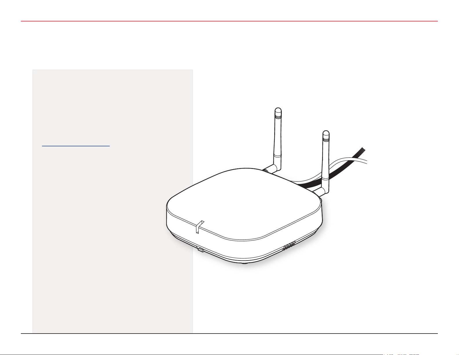
button on the side of the WQXM-PG Wi-Q Gateway. See gure 9.

3 HARDWARE INSTALLATION
3 HARDWARE INSTALLATION
Figure 9 Wi-Fi Enable Button
Wi-Fi Enable Button
• Connect to the WQXM-PG wireless network using a smart
device (ex... tablet, cell phone) or laptop Wi-Fi Connection.
• The Gateway’s Wi-Fi SSID will appear in the list of available wireless connections.
Note: The gateway’s last 6 of the mac-address will correlate to
the Wi-Fi SSID (connection name) and more than one portal’s
wireless network may appear in the list at a time.
Example ---> Mac Address of new Gateway: 0014F500002E
Wi-Fi SSID to use: WiQ-00002E
Click on the network for the portal that is to be congured.
Note: If the portal cannot be logged into using the steps above try
the following troubleshooting steps:
1. Press Wi-Fi button on the side of the Wi-Q Gateway.
2. Reconnect to the Gateway’s unique wireless network connection.
3. Try to login again.
4. Power Cycle the Gateway and attempt to login again once
powered back up.
5. If the ‘Power Cycle’ is not successful and connection to the
to the gateway’s webpage is still inaccessible, then perform
a *Deep-Reset by taking a pin and depressing the reset
button on the Gateway for 10+ seconds at which time the
LED will begin to icker purple. See gure 10.
Figure 10 Wi-Fi Reset Button
WQXM-PG Wi-Q™ Gateway Setup and User Guide | 27
Reset Button

3 HARDWARE INSTALLATION
3 HARDWARE INSTALLATION
6. A purple light will ash conrming the deep reset.
7. Once the deep-reset process has completed, wait 3-4
minutes before attempting to log back into the gateway.
Follow the steps previously mentioned to enable Wi-Fi,
reconnect, and login.
* The Deep Reset will take the settings on the board and restore
them to the factory defaults.
3.2.5.2 Congure the WQXM-PG Gateway
Open the device’s browser window and navigate to the gateway’s
default IP address: 192.168.1.200.
Note: dormakaba recommends Google Chrome as the web brows-
er to navigate the WQXM-PG web pages.
3.2.5.2.1 Login Screen
Login to the gateway.
• The default Username is admin.
• The default Password is password.
Note: The portal will log itself out after 10 minutes of non-use.
Change the default username.
1. Click on the ‘Edit’ icon next to the Username eld.
2. Enter the New Username into the ‘New Username’ and
‘Conrm Username’ elds.
3. Click the ‘Update’ Button to save the changes.
4. Click on the ‘Update’ button to conrm the changes in the
pop-up notication.
5. Click the ‘Close’ button to close the pop-up notication.
3.2.5.2.2 Manage Prole
The rst time a gateway is logged into, the manage prole screen
will appear prompting to change the username or password. The
user will be prompted to change the password every time the
gateway is logged into until it has been changed to something other than the default. To update the username and password after
the initial conguration, click on the username link in the upper
right corner of the screen. In the following image, it is labeled:
Hello, admin!
28 | WQXM-PG Wi-Q™ Gateway Setup and User Guide

3 HARDWARE INSTALLATION
3 HARDWARE INSTALLATION
Change the default password.
1. Click on the ‘Edit’ icon to the right of the ‘Password’ eld.
2. Enter the current password in the ‘Password’ eld.
3. Enter the new password in the ‘New Password’ eld.
4. Enter the new password again in the ‘Conrm Password’
eld.
5. Click the ‘Update’ button to save the changes.
6. Click the ‘Update’ button in the pop-up notication win-
dow to conrm the changes.
7. Click the ‘Close’ button to close the notication window.
Once changes are updated, a pop-up window appears with the
status of the changes being made. Click the ‘Close’ button to
close the pop-up window.
3.2.5.4 Gateway Status Window
The gateway status page provides and overview of the WQXM-PG
gateway conguration, the sign-on key, the number of associated
controllers, channels enabled, and can generate logs for troubleshooting purposes.
WQXM-PG Wi-Q™ Gateway Setup and User Guide | 29

3 HARDWARE INSTALLATION
3.2.5.4.1 Details
• IP Address – Displays the Ethernet IP address of the gate-
way as congured in its current state.
• MAC Address – The gateway’s unique Media Access
Control address that uniquely addresses the device on the
network.
• Time of Last system Reboot – The last date and time the
gateway was reset, or power cycled.
• Current Sign-On Key – 6-digit sign on key associated with
the segment the gateway is associated with.
• Associated Controllers on Gateway – Displays the num-
ber of controllers communicating with the gateway when
the view was initially displayed.
• Wi-Fi IP Address – IPv4 addressed assigned to the Wi-Fi
radio on the gateway.
• Wi-Fi SSID – The Gateway’s wireless network name. This
is always Wi-Q followed by the last six characters of the
device’s unique MAC Address.
• Radio Channels Allowed – The channels currently en-
abled on the Gateway to connect to the Wi-Q controllers.
• Radio 1 Channel – The channel assigned to Wi-Q Radio 1.
• Radio 1 PAN ID – The personal area network ID assigned
to Wi-Q Radio 1.
Note: Radio 1 PAN ID can be edited when in Mercury mode. PAN
IDs only need to be changed if there is a conict with multiple
gateways within RF range of each other. Editing Radio 1 PAN ID
will also change Radio 2 PAN ID. Each gateway uses up to 66 PAN
IDs.
• Radio 2 Channel – The channel assigned to Wi-Q Radio 2.
• Radio 2 PAN ID – The personal area network ID assigned
to Wi-Q Radio 2.
3.2.5.4.1.1 Wireless Controllers
At the bottom of the Gateway Status window is a list of the
associated Wi-Q Controllers and their attributes.
• ACR ID – The Reader ID when the portal is in Mercury
mode with the LP4502 Access Control Board. This eld will
be blank when Mercury Mode is not in use.
• MAC Address – The Reader’s unique Media Access Con-
trol address that uniquely addresses the device on the
network.
• Radio Channel – The channel the door controller is com-
municating on with the gateway.
• Associate Time – The date and time the Wi-Q door con-
troller associated with the gateway.
• Last Beacon Time – The last date and time the Wi-Q
door controller beaconed information up to the gateway.
• Pending Operations – Progress percentage of pending
messages from the door controller to the gateway.
• Package Count – The number of pending messages in the
current queue that the gateway has received from the Wi-Q
door controller.
• Firmware Version – The current version of door controller
rmware on the Wi-Q device.
30 | WQXM-PG Wi-Q™ Gateway Setup and User Guide

3 HARDWARE INSTALLATION
• Portal RSSI – Portal RSSI is the how well the gateway
received a signal from the Wi-Q door controller. The signal
strength ranges from -18 (highest/best) to -91 (lowest/
worst). Ideally, this value should be -75dB or better.
• Reader RSSI – Reader RSSI is the how well the Wi-Q door
controller receives a signal from the gateway. The signal
strength ranges from -18 (highest/best) to -91 (lowest/
worst). Ideally, this should be -65dB or better.
• Flags – The Flags indicate the device status. Common de-
vice statuses for Wi-Q controllers when they are connected
to a gateway are below:
□ 010001 – Controller initial connection to the gateway.
□ 30207 – Controller connected to the gateway and is
waiting for segment updates.
□ 30063 – Controller has a deep reset command pending.
□ 30017 – Controller waiting to be pulled into the seg-
ment and has not received segment updates.
□ 30007 – Controller has received segment updates and
is waiting in the ‘New Segment Items’ folder in Wi-Q
AMS Conguration software.
□ 30043 – Controller is signed into the ACS, connected,
congured, and not locked to the gateway.
□ 30053 – Controller is taking conguration updates.
□ 32043 – Controller is signed into the ACS, connected,
congured, and locked to the gateway.
□ 32243 – Controller is locked to portal but has not been
added to an access level or a direct assignment to a
User. No user credentials are assigned to the controller
in the software.
□ 38053 – Controller has a rmware update pending.
□ 38043 – Controller is receiving a rmware update.
□ 32207 – Controller completed the rmware update and
is waiting for updates from the portal.
• Pending Messages – The letters in the pending messag-
es column are update messages that are being sent to the
controller.
□ S – Segment Information (Pin length, DST Times)
□ C – Card Formats
□ L – Controller Conguration (beacon time settings,
channels, transaction masks, etc.)
□ U – User Credentials and Properties
□ T – Timezone Intervals
□ I – WAC I/O
□ F – Firmware
□ P – Ping (missing LIF data after association or updates)
3.2.5.4.1.2 Generate Logs
Click on the ‘Generate Logs’ button in the upper right corner of
the gateway status screen.
The “Technician” and “Advanced” log buttons allows the installer/technician to assist dormakaba BEST software support in troubleshooting an issue. These logs may be used by the local installer
to troubleshoot or verify the credentials are all making it to the
controllers or requested during a troubleshooting session with the
software technical support engineers.
WQXM-PG Wi-Q™ Gateway Setup and User Guide | 31

3 HARDWARE INSTALLATION
To generate logs, do the following:
TECHNICIAN LOG
The TECHNICIAN LOG button is used to aid installers/technicians
when the Wi-Q System is setup in Mercury mode. This log provides information on when each controller was last updated with
user credentials. This can aid a technician to determine if there is
a problem pushing changes in user credentials to the door controllers.
There are four elds in the log le: Credential Number, MAC Address, download status, lastupdate
• Credential Number – provides the credential pushed to
the door controller
• MAC Address – MAC address identier for the door con-
troller
• Download status – shows if the door controller has
received the user update. If download completed to door
controller with ACK then download status = 1. If CRCs
match with what is already in the controller download
status will = 0.
• Lastupdate – last time the door controller recognized that
it received an update from the ACS
Note: Adding the credentials to an access level, clearance, or
reader will not automatically propagate the information to the
readers. Time must be allowed for the beacon cycle and possible
network lag.
ADVANCED LOG
Advanced logs are used by Engineering to perform advanced troubleshooting. These logs are encrypted and can only be decrypted
by our engineering group. These logs may occasionally be requested by software technical support during a troubleshooting session.
Clicking on the “ADVANCED LOG” button will download the log
le to the browser’s download location and should be forwarded
to technical support via email at bas.support.best.us@dormakaba.
com. The le will be named with the following naming convention:
Portal_0014fmacaddress_201907datetime.tar.gz.enc
3.2.5.5 Gateway Menu
The GATEWAY page has multiple sections of this page with dierent functions as the windows are scrolled down. The primary focus
of this page is to congure the gateway for the customer network.
This page allows the rmware to be upgraded on the gateway
should there be an updated rmware release the technician or
system administrator the ability to send a reboot command to the
device. The conguration section of the Gateway menu allows the
Ethernet network card conguration of the IP address, update to
the Portal Service Port as well as SSL certicate generation and
enablement.
32 | WQXM-PG Wi-Q™ Gateway Setup and User Guide

3 HARDWARE INSTALLATION
pressed for a second time to disable the Wi-Fi on the WQXM-PG.
Additionally, if nothing has been connected to WQXM-PG wireless
network for 30 minutes, the internal Wi-Fi network will automatically disable.
3.2.5.5.1.1 DHCP
A static IP Address of 192.168.1.200 is the default IP of the
WQXM-PG for rst time conguration via the LAN port, however, the gateway has built in DHCP functionality allowing network
administrators to assign portal IP’s dynamically via DHCP. To take
advantage of this feature, verify the DHCP checkbox is selected
instead of manually assigning an IP address. Provide the customer’s local Network Administrator with the list of MAC Addresses and
other information as required by the customer.
To complete enabling the DHCP setting, click on the ‘Save’ button
at the bottom of the screen to save the changes.
3.2.5.5.1 Assigning an IP Address
Conguration changes on the gateway are only available via the
portal’s wireless network after the “Enable Wi-Fi” button has
been pushed. The IP address for the WQXM-PG wireless network
is a static 192.168.3.200 and cannot be changed. Once the IP
Address has been updated, the enable Wi-Fi button can be de-
3.2.5.5.1.2 Static IP Assignment
The WQXM-PG Gateway has built in exibility to use IPv4 as well
as IPv6 addresses. Contact the local IT or network administrators
for IP addresses available for each device. To assign the IP addresses to the devices, verify the DHCP checkbox is not selected
and enter in the IP address as specied into the IP address elds.
Verify that the correct subnet mask as well as default gateway for
the assigned IP schema.
To assign a static IP address congure the following elds:
• IPv4 Address or IPv6 Address
• Subnet mask (for IPv4 Addresses Only)
• Gateway (for IPv4 Addresses Only)
WQXM-PG Wi-Q™ Gateway Setup and User Guide | 33

3 HARDWARE INSTALLATION
To save the changes for the Static IP address, click on the ‘Save’
button at the bottom of the window.
3.2.5.5.1.3 Portal Service Port
The default portal service port for the ACS to communicate to the
gateway is port 8000. The portal service port is the port used to
connect to and congure the gateway. If a port other than 8000 is
required, the portal service cannot be 80, 443 nor within the range
of 13000-13019. Valid ports are within the range of 0-65 or 535.
3.2.5.5.1.4 Enabling SSL
AES encryption is used for the wireless communication from the
gateway to the radios. If SSL is also required to encrypt the communication between the gateway and the ACS as well as between
the gateway and the browser, the WQXM-PG gateway can issue a
self-sign SSL certicate for use with the ACS. To enable SSL, do
the following:
1. Click on the ‘Enable SSL’ checkbox in the gateway cong-
uration page.
2. Click on the ‘GET CERTIFICATE’ button to download the
portal’s SSL certicate. This portal certicate will download
to the predetermined location on the local browser.
3. Click on the ‘Save’ button to save the SSL setting.
4. Locate the SSL Certicate on the PC where the certicate
was downloaded and upload the SSL certicate into the
ACS.
Note: SSL certicates expire after 20 years. Please take a note of
the expiration date and plan to reissue the certicates and upload
them before the SSL expiration to prevent disruption in communication between the ACS and the gateways.
3.2.5.5.1.5 Update Portal Firmware
Occasionally it is necessary to upgrade the portal rmware. To
upgrade the portal rmware, do the following:
1. Navigate to the Gateway menu option in the WQXM-PG
webpage.
2. Click on the ‘Update’ button towards the bottom of the
Gateway page.
34 | WQXM-PG Wi-Q™ Gateway Setup and User Guide

3 HARDWARE INSTALLATION
In the rmware upgrade pop-up screen, click on the ‘Browse’
button to browse to the rmware le.
3. Browse to the previously extracted .gzhe portal rmware
le and click the ‘Open’ button to upload the le.
4. The selected le will be listed in the pop-up window. Verify
it is correct and click the ‘Apply’ button.
5. The rmware will be applied to the gateway. The gateway’s
LED will ash aqua when it downloads the rmware.
3.2.5.5.1.6 Reboot Gateway
Occasionally it may be necessary to reboot the WQXM-PG gateway.
This action can also be referred to as a reset. To reboot the gateway do the following:
1. Navigate to the ‘Gateway’ menu option of the Gateway.
2. Scroll to the bottom of the screen.
3. Click the ‘REBOOT GATEWAY’ button.
4. A pop-up window will appear asking if you are sure you
want to reboot the gateway. Any changes made and that
have not been save will be lost. Click the ‘RESET’ button
to continue.
5. The gateway will reboot immediately. During a reboot, the
gateway will ash purple. Once it reconnects to the ACS,
the LED will display a solid green light.
3.2.5.5.1.7 Factory Reset the Gateway
Occasionally, situations arise that require the gateway to be reset
back to factory default settings. To perform a factory reset, do the
following:
1. Remove gateway from enclosure or from the mounted
location.
2. On the back of the gateway locate deep reset button next
to the Ethernet inlet. See gure 11.
3. Push and hold the deep reset button using a small implement such as a paper clip for more than 10 seconds.
Figure 11 Wi-Fi Reset Button
Reset Button
WQXM-PG Wi-Q™ Gateway Setup and User Guide | 35

3 HARDWARE INSTALLATION
3.2.5.6 INTERFACE MENU
The interface menu option on the WQXM-PG is for use when the
gateway will be used in a 3rd party ACS. This menu option will
allow the WQXM-PG to be congured to communicate with the
mercury LP4502 board.
3.2.5.6 1 Enable Mercury Mode
Mercury mode is enabled when using the WQXM-PG with a 3rd
party ACS and the mercury controller board LP-4502 or MP-4502
v1.29 or higher.
1. Click on the “Interface” menu option to navigate to the
Mercury Interface Conguration page.
2. Click on the “Enable Mercury Mode” checkbox to select
it. It will turn red when selected and enabled.
3. If SSL will be used, click on the “Enable SSL” checkbox
to enable SSL for use with the Mercury LP4502 controller
board.
□ Click on the ‘Enable SSL’ checkbox in the gateway
conguration page.
□ Click on the ‘GET CERTIFICATE’ button to download
the portal’s SSL certicate.
□ Click on the ‘Save’ button to save the SSL setting.
□ Upload the SSL certicate into the ACS.
4. Click on the “Update” button to apply the settings.
5. Once checked, the ‘Enable Mercury Mode’ will validate
this change and display a pop-up notication window.
36 | WQXM-PG Wi-Q™ Gateway Setup and User Guide
6. Click the ‘Close’ button and ll out the remaining elds on
the Mercury Interface Conguration screen as follows:
7. Enter the Mercury LP4502 IPv4 Address.

3 HARDWARE INSTALLATION
8. Port 1883 is used for portal service communication by
default. If port 1883 is already in use and the customer
would prefer the port to be something else, change this
port number in the LP4502 as well as in the WQXM-PG
Mercury Interface Conguration.
9. Enter the Mercury LP4502 Username and Password. Please
note this will need to be updated each time the LP4502 Username and Password is changed.
12. The system will then validate all changes and pop open a
notication window showing “Save Successful”. Click the
“Close” button to continue.
10. After making all updates, a notication window will appear
to verify the updates being made to the WQXM-PG Mercury
Mode conguration.
11. Verify the changes are correct and click the “UPDATE”
button to commit the changes.
Note: If changes are required, click the “CANCEL” button to go
back and update the form.
3.2.5.6.2 Update the IP Conguration for the LP4502
Mercury Board
• Make sure all the dip-switches on the LP4502 Mercury
board are in the OFF state/position (see below). If they
are not, then turn them to the OFF position and reboot the
LP4502.
• Next, go to the UI (user interface) webpage for the Mercury board by typing the IP address of the board into a web
browser’s URL.
WQXM-PG Wi-Q™ Gateway Setup and User Guide | 37

3 HARDWARE INSTALLATION
3.2.5.6.3 Adding Sign-On Credentials to the WQXM-PG
(Gateway)
From the Portals UI homepage click on the ‘CREDENTIALS’ tab.
From the Credentials page, click on the ‘ADD NEW SIGN ON
CREDENTIAL’ button on right side of screen.
Note: If “Wiegand/Proximity” card is chosen, a prompt will appear
to conrm and/or edit the “Bit Length” for the card.
Enter credential criteria as prompted:
• Credential Name – Name of credentialed user to add
• Type – Magnetic Stripe or Wiegand/Proximity Card
• Credential Number – Manually enter card number
Alternativly, attach a USB card reader; press the ‘SCAN’ button;
and scan the card with the reader.
When all credential information has been entered, click ‘SAVE’ on
the Edit Credential page.
Click the ‘CONFIRM’ button on the pop-up notication window to
add the new sign on credential.
38 | WQXM-PG Wi-Q™ Gateway Setup and User Guide

3 HARDWARE INSTALLATION
Credentials already in the system can be edited (or deleted) by
clicking the ‘EDIT’ button on the Credentials home screen, and
saved once done.
Credentials can be deleted from the Credentials screen as well.
Choose the user to be removed, click the ‘DELETE’ button.
Click ‘CONFIRM’ on the pop-up notication window when editing
is complete.
3.2.5.6.4 Sign On Wi-Q Controllers to the WQXM-PG
The enrollment process for the Wi-Q controllers requires a default
token followed by a sign-on token and can take 20-30 seconds.
Sign-on is also conrmed with a three-tone increasing frequency
beep1-beep2-beep3 and 3 ashes of the green LED on the lock. If
sign-on fails there will be three beeps with decreasing tones and 3
red LED’s.
Note: If the controller is a WAC or Omnilock, there will not be any
audible beeps.
3.2.5.6.4.1 Keypad Method
• If a keypad is attached to the wireless door controller
(WDC) do the following:
□ Enter 5678# and then within 3 seconds enter the
six-digit sign-on key then the # key.
□ Example: 5678# 816645#
• If there is a Keypad on the Omnilock or Wireless Access
Controller (WAC) do the following:
□ Enter 5678 and then within 3 seconds enter the
six-digit sign-on key.
□ Example: 5678 816645
• The Wi-Q controller should sign on to the WQXM-PG and
display the controller’s unique MAC Address at the bottom
of the STATUS page.
WQXM-PG Wi-Q™ Gateway Setup and User Guide | 39

3 HARDWARE INSTALLATION
3.2.5.6.4.2 Magnetic Card Method
• If the WDC, WAC or Omnilock is equipped with a Magnetic
card reader do the following:
□ Present the Magnetic Temporary Operator badge that
comes with the Wi-Q lock.
□ Within 3 seconds present the Sign-On Credential
created in the Credentials screen of the WQXM-PG
previously.
• The Wi-Q controller should sign on to the WQXM-PG and
display the controller’s unique MAC Address at the bottom
of the STATUS page.
3.2.5.6.4.3 Proximity Card Method
• If the WDC, WAC or Omnilock is equipped with a Proximity
card reader do the following:
□ Present the Proximity Temporary Operator badge that
comes with the Wi-Q lock.
□ Within 3 seconds present the Sign-On Credential
created in the Credentials screen of the WQXM-PG
previously.
• The Wi-Q controller should sign on to the WQXM-PG and
display the controller’s unique MAC Address at the bottom
of the STATUS page.
3.2.5.6 Conguring the Mercury Panel for use with the
WQXM-PG
3.2.5.6.1 Logging into the Mercury Board UI (User Interface)
1. Open an internet browser (Google Chrome is recommended)
2. Log into the UI for the LP-4502/MP-4502 Mercury Board
by going to (192.168.2.251) in the URL eld of the browser. Then click on the ‘Click Here to Login’ link.
3. Enter the case-sensitive Username of ‘admin’ and Password of ‘password’ into the appropriate elds.
40 | WQXM-PG Wi-Q™ Gateway Setup and User Guide

3 HARDWARE INSTALLATION
The Mercury Board User Interface page (aka...LP4502 Conguration Manager) will appear as follows:
3.2.5.6.2 Updating/Creating Users & Passwords
1. Log into the LP4502 Conguration Manager (aka...LP4502
Mercury Board Interface).
2. Click on the “USER” tab on the left-side of the LP4502
home screen.
3.2.5.6.3 Load SSL Certicates into the Mercury panel
On the Mercury panel some custom settings must be congured as
follows:
Note: Steps 1-4 are one-time conguration after hard reset of
the Mercury panel.
1. Network – Set IPV4 conguration as required.
2. Host Comm – Set the Data Security drop-down to “TLS if
available”.
3. Users:
□ Option – Create a New User. Level 1. This is for alter-
nate login other than admin/password. This new user
will not require Switch 1 to be ON to log in.
□ Option – Check “Enable Diagnostic Logging” if
troubleshooting is required.
4. Security Options – Check “Enable Encrypted Parti-
tion.”
5. Over Watch – Create user username and password. This
should match the username and the password set in the
WQXM-PG.
6. Apply Settings – Click on the ‘Apply Settings, Reboot’
button to apply the settings and reboot the Mercury board.
The board will take approximate XX minutes to complete
this process. Please w
log back into the Mercury board.
7. From the Load Certicates tab
□ Choose certicate le: client.crt.
□ Choose private key le: client.pem.
□ Press “Load certicate les.”
X minutes before attempting to
ait
Note: The certicate can be generated through the WQXM-PG or
through a 3rd party.
WQXM-PG Wi-Q™ Gateway Setup and User Guide | 41

3 HARDWARE INSTALLATION
8. Click on the Apply Settings tab. Click on the “Apply Settings, Reboot” button.
3.2.6 Install Wireless Access Controllers (Task 5)
Installing a Wireless Access Controller
The Wi-Q Technology Wireless Access Controller (WAC) provides
an optional, cost eective way to retrot an existing hard-wired
application, or where the installed controller may be obsolete or
unable to handle additional controller inputs. It supports Wiegand
compatible keypad controllers and is congured and monitored in
the Access Control Software, just like a standard controller.
42 | WQXM-PG Wi-Q™ Gateway Setup and User Guide
Note: Please check with your dormakaba representative for a list
of compatible controllers.

3 HARDWARE INSTALLATION
Figure 12: Wireless Access Controller
Using the Wireless Access Controller (Figure 12), controllers or
other I/O devices can be added to an overall wireless solution
without the high cost of installing conduit such as RS485 or CAT5
to the controller. Position the controller at the door or where suitable above the ceiling tile.
The most common installation site is inside an existing protected
area such as a locked room or other secure enclosure, or above
the door in the ceiling.
3.2.6.1 Installation
Specic installation methods are dependent on the device type and
conguration of the system; therefore, the WAC should be in-
stalled by a trained technician using the instructions provided with
the controller.
WARNING: Wireless Access Controllers are intended for use
in indoor or protected area. For other applications, such as
outdoor use, contact the factory for the appropriate NEMA
enclosure. Changes or modications not expressly approved
by dormakaba could void the user’s authority to operate the
equipment.
3.2.6.2 Wireless Access Control Wiring
The Wireless Access Controller (WAC) can be installed with its own
12 VDC power supply or slaved to the existing installation. Figure
13 is a wiring diagram illustrating both congurations. Dotted lines
represent optional connections for the slaved conguration.
Figure 13 Connecting Devices to a WAC
(+ Power)
(–)
(+)
STRIKE NC (Relay 1)
Electric
Lock
Connect
as required
Weigand
Output
Reader
STRIKE COM (Relay 1)
STRIKE NO (Relay 1)
SHUNT NC (Relay 2)
SHUNT COM (Relay 2)
SHUNT NC (Relay 2)
KEY (I/O)
GND
RQE (I/O)
DSM (I/O)
GND
DLS (I/O)
WIEGAND 0 (I/O)
GND
WIEGAND 1 (I/O)
RED
GND
GRN
(+ Power)
ANT
DO NOT USE
GND
3.3V (10mA MAX)
DO NOT USE
– DC 9-24V
+ DC 9-24V
– DC 9-24V
+ DC 9-24V
RESERVED FOR
FUTURE USE
+12 VDC
12 VDC
Strike Power
Supply
by Others
GND
WQXM-PG Wi-Q™ Gateway Setup and User Guide | 43

3 HARDWARE INSTALLATION
Once the WAC is installed and all points connected, it will be
recognized by the ACS as a ‘Controller’ in the system. The WAC is
congured in an almost identical manner as a Controller.
3.2.6.3 Resetting the WAC
The wireless access controller (WAC) may occasionally need a soft
reset or a factory reset.
A soft reset would be required if the WAC has stopped communicating with the gateway and an Anti-Tamper event does not
re-establish communication. To reset the WAC, push and hold the
reset button located on the controller board next to the antenna
inlet until the rst green LED ash. Release immediately after the
rst green LED ashes.
The deep reset restores the WAC to factory default. To deep reset
the WAC, push and hold the reset button on the WAC located next
to the antenna and wait until the 3 slow red LED ashes.
3.2.7 Install Wireless Door Controllers (Task 6)
This section provides general instructions for installing the wireless door controllers. Complete instructions for installing locks are
packaged with the hardware.
• Wi-Q and Omnilock Technology locks will work from -31°F
to 151°F.
Note: Extreme heat will cause a reduction in wireless signal
strength and can cause a loss of connectivity while the heat remains.
Note: Alkaline batteries cease to operate if they reach a tempera-
ture of -20°F.
Wi-Q Technology controllers are designed for use on 1-3/4-inch
doors. If the locks will be installed on non-standard doors, contact
dormakaba Customer Service for more information.
Lockset instructions are given for right-hand doors (as determined
from outside the door). If the door is left hand, see the instructions provided with the lockset for hand change instructions.
If the locksets will be installed on unprepared (un-drilled) doors,
use the template provided with that specic lockset.
Please refer to the instructions provided with the lock to complete
these steps. Once this is done, check controller operation as described in the following paragraphs.
Before Beginning
Before beginning, take a few moments to review the following
considerations:
• Record the device MAC address before installing device.
This is needed when conguring the controller in the ACS
or the LP4502 Mercury Interface Board.
44 | WQXM-PG Wi-Q™ Gateway Setup and User Guide
Check Controller Operation
Verify controller operation using the steps appropriate for the
controller type (Proximity Card, Magnetic Card or keypad). If the
system does not operate properly, see the troubleshooting table,
at the end of the section.

3 HARDWARE INSTALLATION
Proximity Card Check
If the Wi-Q controller has a proximity card reader, the Temporary
Operator Card (supplied with the controller) and the Sign-on card
(created in the ACS Software or the web interface of the LP4502
board) are both required to sign on the readers.
To perform a proximity card verication:
1. Select the Temporary Operator Card supplied with the
controller.
2. Present the Temporary Operator Card to the proximity
bezel at the face of the reader. The light on top of the con-
troller will ash green once and the lock will unlock. After
3 seconds, the controller will ash green and lock.
3. While unlocked, check for proper lock operation.
Magnetic Card Check
If Wi-Q Controller has a magnetic card reader, the Temporary Operator Card (supplied with the controller) and Sign-on Card (created in the ACS Software or the web interface of the LP4502 board)
are both needed to sign on the readers.
To perform a magnetic stripe card verication:
1. Determine if the magnetic card type is Track-1, Track-2 or
Track-3.
2. Select the Temporary Operator card supplied with the
controller.
□ If the lock is a WDC, slide the magnetic card through
the slot in the face of the reader bezel with the print
facing the left and the arrow toward the door.
□ If the lock is an Omnilock, insert the magnetic card
into the top of the reader with the print facing you and
the arrow pointing down and pull back out.
□ The magnetic stripe on the card should be aligned
with the ‘V’ mark by the card slot. The lights on the
top of the controller will ash green once and unlock,
then during the open delay time, it will ash green ve
times. Once this occurs, the card controller light will
ash red and lock.
3. While unlocked, check for proper lock operation.
Keypad Check
If the controller is a keypad type, perform the following steps:
WDC
1. At the keypad, enter the default Programmer-ID, 1234#.
The green light on top of the card controller will ash once
and the lock will unlock, then during the open delay time,
it will ash green ve times. Once this occurs, the control-
ler red light will ash and the lock will relock.
2. While unlocked, check for proper lock operation.
OMW
1. At the keypad, enter the default Programmer-ID, 1234.
The green light on top of the card controller will ash once
and the lock will unlock, then during the open delay time,
it will ash green ve times. Once this occurs, the control-
ler red light will ash and the lock will relock.
2. While unlocked, check for proper lock operation.
WQXM-PG Wi-Q™ Gateway Setup and User Guide | 45

3 HARDWARE INSTALLATION
Troubleshooting WDC and Omnilock locks
If the mechanism doesn’t unlock, refer to the following table:
LEDs lights Sounder Try
Single Red Flash -------- Use the card at a moderate
speed
Red Flashes 3 short
tones
Green Flashes -------- Check the motor connection on
Green and Red
Alternating
Flashes
-------- Check the motor connection
Use the temporary operator card
provided with the lock.
Or
Perform a deep reset to restore
to the factory default settings
(the lock may already be associated (programmed).
the Omnilock.
is secured on the WDC at the
connector between the wiring
harnesses and at the controller
board.
Troubleshooting the WAC\SDC
LEDs lights Sounder Try
Single Red Flash -------- Use the card at a moderate
speed
Red Flashes 3 short tones Use the temporary operator
card provided with the lock
Or
Perform a deep reset to
restore to the factory default settings (the lock may
already be associated (programmed)
Green Flashes -------- Check the motor connection
on the Omnilock.
Green and Red
Alternating
Flashes
For additional troubleshooting instructions, see the Service Manual
for the hardware components and assemblies.
-------- Check the motor connection
to the WDC board as well
as the harnesses. Verify all
connections are tight.
46 | WQXM-PG Wi-Q™ Gateway Setup and User Guide
Once the installed controllers have been tested, they are ready to
be signed into LP4502 or ACS. To do this, ACS must be installed
on the Host computer or the LP4502 congured and communicating with the ACS as well as the WQXM-PG gateways. At a minimum, the segment should be created and the gateways online
and communicating to the ACS or the LP4502 Mercury controller
board. For more information see the “Congure Gateways (Task
4)” section on page (26).

3 HARDWARE INSTALLATION
Once this is done, return to the site and sign-on the controllers.
For more information see the “Sign on and Congure Controllers
(Task 7)” section on page 47.
3.2.8 Sign-On Wi-Q Controllers (Task 7)
To successfully sign on Wi-Q controllers, the temporary operator
card as well as the Sign-on cards created in the ACS or the WQXMPG are both needed. If the Wi-Q reader has a keypad, the keypad
code can be used to sign the readers onto the WQXM-PG or the
ACS.
Keypad Method
1. Test the Reader – Enter 1 2 3 4 # on a WDC or 1 2 3 4
on the WAC or Omnilock
□ The reader should display the green LED and Unlock
2. Prepare the Reader to receive the Sign on Code – En-
ter 5 6 7 8# on the WDC or 1 2 3 4 on the WAC or Omnilock
3. Enter the Segment’s Unique Sign-on Key – Enter the
6-digit sign-on key in the ACS or on the Segment tab of
the WQXM-PG followed by the # key if the reader is a
WDC. If the reader is a WAC or Omnilock, the # key is not
needed.
□ Example – key sequence for the WDC: 1 2 3 4 # 5 6
7 5 6 7#
□ Example – key sequence for the WAC or the Om-
nilock: 5 6 7 8 5 6 7 5 6 7
Note: The keypad codes 5678 and the sign-on key should be
presented in rapid success. It is important to not let the controller
time out before entering the 6-digit sign on code. There should be
no more than a 2 second delay between the 5 6 7 8 (#) keypad
entry and the six-digit code keypad entry.
Magnetic Card Method
1. Test the Reader – Swipe the temporary operator card
through the reader bezel of the WDC or Wall Mounted
magnetic reader wired to a WAC
□ The WDC controller will display a brief green LED and
unlock.
□ The Omnilock controller will display a brief green LED
and unlock.
□ The WAC will display a green LED on the controller
board and unlock.
2. Present the Temporary Operator badge to the reader, look
for the green LED and the reader to unlock.
3. Immediately present the sign-on card to the reader.
Proximity Card Method
1. Test the Reader – Present the temporary operator card
to the face of the reader bezel on the WDC , Omnilock or
Wall Mounted proximity reader wired to a WAC
□ The WDC controller will display a brief green LED and
unlock.
□ The Omnilock controller will display a brief green LED
and unlock.
□ The WAC will display a green LED on the controller
board and unlock.
2. Present the Temporary Operator badge to the reader, look
for the green LED and the reader to unlock.
3. Immediately present the sign-on card to the reader.
WQXM-PG Wi-Q™ Gateway Setup and User Guide | 47

3 HARDWARE INSTALLATION
If the reader does not successfully sign-on to the WQXM-PG, repeat the steps above ensuring that the delay between the temporary badge or keypad code 5 6 7 8 and the segment sign on key
or card is minimal. Waiting too long between steps will result in
controller sign-on failure.
Behavior Try This
3 Red Flashes at the end of
the Sign-On sequence.
Temporary card does not
unlock the reader.
Tried to sign on the reader multiple times without
success.
3.2.8.1 Verify Sign-On Success
Once the readers have received the sign on sequence, the readers
will each display a LED sequence indicating they are initiating the
radios and will indicate sign-on success or failure.
WDC
The Blue LED will illuminate when the radios are initiating. The
controller will alternate the red, green and blue LED’s while the
controller seeks to establish communication with the WQXM-PG
radios.
Try signing the controller in again.
Deep reset the controller and try
again.
Verify the keypad code is correct
or the card that is used as the
segment sign on card, is correct.
If the sign-on procedure was not a success, the nal LEDs will
be 3 quick RED ashes accompanied by 3 beeps that go down in
pitch. LED activity will stop.
WAC
The Blue LED will illuminate when the radios are initiating. The
controller will alternate the red, green and blue LED’s while the
controller seeks to establish communication with the WQXM-PG
radios.
If the controller sign-on was a success, the nal 3 LEDs will be 3
quick green. The blue LED will continue to ash as the controller
receives segment information from the WQXM-PG.
If the sign-on procedure was not a success, the nal LEDs will be
3 quick RED ashes. LED activity will stop.
Omnilock
The Omnilock is not equipped with a blue LED, therefor the light
sequence is dierent than that of the WDC and WAC. The controller will alternate the red and green while the controller seeks to
establish communication with the WQXM-PG radios.
If the controller sign-on was a success, the nal 3 LEDs will be 3
quick green ashes. LED activity will continue while the controller
receives segment data from the WQXM-PG.
If the controller sign-on was a success, the nal 3 LEDs will be 3
quick green ashes accompanied by 3 tones that go up in pitch.
The blue LED will ash as the controller receives information from
the controller.
48 | WQXM-PG Wi-Q™ Gateway Setup and User Guide
If the sign-on procedure was not a success, the nal LEDs will be
3 quick RED ashes. LED activity will stop.

3 HARDWARE INSTALLATION
3.2.8.1 Verify Signal Strength and Packet Ratio Using Survey Mode
Prior to installation, the Wi-Q Technology Site Survey feature in
the WQXM-PG should have been used to verify basic controller
signal strength. Once the Controllers are signed on, the WQXM-PG
Site Survey webpage can be used to verify the signal strength and
packet ratio to verify all information is being sent successfully to
and from the Wi-Q controllers.
To do this, please do the following:
1. Login to the WQXM-PG by navigating to the IPv4 address
using an internet browser.
2. Click on the ‘SURVEY MODE’ button.
3. Check the boxes next to the reader(s) connected to the
gateway to select them for the Survey.
4. Click on the ‘Start Survey’ button to begin surveying the
locks.
Portal Signal Strength
The Portal RSSI value indicates how well the portal receives signal
from the door controller and should be -75dB or better. The Survey
mode charts in the WQXM-PG denotes the lowest limit by the blue
dashed line in the Signal Strength chart. If the Portal RSSI value
is below the limit, please reposition the gateway or the Antennas
to improve signal strength. It may also be possible that another
portal is required for adequate coverage.
The WQXM-PG Gateway will begin logging the portal packet ratio,
the reader packet ratio as well as the signal strength at the portal
and the reader.
WQXM-PG Wi-Q™ Gateway Setup and User Guide | 49

3 HARDWARE INSTALLATION
Reader Signal Strength
The Reader RSSI value indicates how well the reader is receiving
signal from the gateway and should be at least -65dB or better
denoted on the chart with the blue dashed line. If the reader RSSI
value is below the recommended limit check the reader antenna
and the gray antenna jumper cable to verify there is not damage
to them.
Also, it may be required the WQXM-PG or the antennas need to be
repositioned so the reader can hear the WQXM-PG more clearly.
Packet Transfer Ratio
It is recommended that the packet transfer ratio rate is 80% or
better. This value indicates how ecient the communication is between the readers and the WQXM-PG as well as how much interference maybe in the area. If this value is below 80%, the reader
will not receive all the conguration data. To troubleshoot the
portal packet ratio, update the reader statistics to poll every 10
seconds instead of once a day while running the survey tool in the
WQXM-PG. Please remember to change the reader statistics back
to only poll 1 time a day once the troubleshooting is complete.
the ZigBee channels. If the location has other wireless devices or
networking using the 2.4 frequency, please orient the antennas
away from these devices to manage interference. It may be required to work with local personnel to manage the wireless environment to prevent causing interference with other Wi-Fi installations and products.
Note: OnGuard 7.4 and higher Wi-Q Interfaced installations using
the WQXM-PG require global statistics update poll rates to be
made during troubleshooting. Please contact dormakaba technical
support for direction at 800-392-5209 or via email at bas.support.
best.us@dormakaba.com.
It is imperative to consider the wireless environment and the
placement of the gateway and its antennas during troubleshooting. The gateway communicates on the 2.4 GHz frequency using
50 | WQXM-PG Wi-Q™ Gateway Setup and User Guide
 Loading...