

Page 1

www.stanleyblackanddecker.com/Zeus
QEL 200
User Guide
Wireless & Stand-Alone
Page 2

Copyright© 2013 Stanley Security Solutions, Inc.
All rights reserved.
Information in this document is subject to change without notice and does not represent a commitment on the
part of Stanley Security Solutions, Inc. The software described in this document are furnished under a license
agreement or nondisclosure agreement.
This publication is intended to be an accurate description and set of instructions pertaining to its subject matter.
However, as with any publication of this complexity, errors or omissions are possible. Please call Stanley Security
Solutions, Inc at (317) 849-2250 if you see any errors or have any questions. No part of this manual and/or
databases may be reproduced or transmitted in any form or by any means, electronic or mechanical, including
photocopying, recording, or information storage and retrieval systems, for any purpose, without the express written
permission of Stanley Security Solutions, Inc.
This document is distributed as is, without warranty of any kind, either express or implied, respecting the
contents of this book, including but not limited to implied warranties for the publication’s quality, performance,
merchantability, or tness for any particular purpose. Neither Stanley Security Solutions, Inc, nor its dealers or
distributors shall be liable to the user or any other person or entity with respect to any liability, loss, or damage
caused or alleged to be caused directly or indirectly by this publication.
QEL 200 is a registered trademark of Stanley Security Solutions, Inc.
Intelli-M is a registered trademark of Innias Inc.
Microsoft, Windows, CE, and ActiveSync are registered trademarks of Microsoft Corporation.
A86094-01 • April 2013
Page 3

FCC Certication
This equipment has been tested and found to comply with the limits for Class B Digital Device, pursuant to Part
15 of the FCC Rules. These limits are designed to provide reasonable protection against harmful interference in
a residential installation. This equipment generates and can radiate radio frequency energy and, if not installed
and used in accordance with the instructions, may cause harmful interference to radio communications. However,
there is no guarantee that interference will not occur in a particular installation. If this equipment does cause
harmful interference to radio or television reception, which can be determined by turning the equipment off and
on, you can try to correct the interference by taking one or more of the following measures:
Reorient or relocate the receiving antenna
Increase the separation between the equipment and receiver
Connect the equipment into an outlet on a circuit different from that to which the receiver is connected
Consult the dealer or an experienced radio/TV technician for help.
This device complies with Industry Canada license-exempt RSS standard(s). Operation is subject to the following
two conditions: (1) this device may not cause interference, and (2) this device must accept any interference,
including interference that may cause undesired operation of the device.
Under Industry Canada regulations, this radio transmitter may only operate using an antenna of a type and
maximum (or lesser) gain approved for the transmitter by Industry Canada. To reduce potential radio interference
to other users, the antenna type and its gain should be so chosen that the equivalent isotropically radiated power
(e.i.r.p.) is not more than that necessary for successful communication.
This radio transmitter (identify the device by certication number, or model number if Category II) has been
approved by Industry Canada to operate with the antenna types listed below with the maximum permissible
gain and required antenna impedance for each antenna type indicated. Antenna types not included in this list,
having a gain greater than the maximum gain indicated for that type, are strictly prohibited for use with this device
Approved antennas are listed below.
Cet appareil est conforme aux normes d’Industrie Canada exempts de licence RSS (s). Son fonctionnement est
soumis aux deux conditions suivantes: (1) cet appareil ne doit pas provoquer d’interférences, et (2) cet appareil
doit accepter toute interférence, y compris les interférences pouvant provoquer un fonctionnement indésirable de
l’appareil.
En vertu de la réglementation de l’industrie du Canada, cet émetteur de radio ne peut fonctionner à l’aide d’une
antenne d’un type et un maximum (ou moins) Gain approuvé pour l’émetteur par Industrie Canada. Pour réduire
le risque d’interférence aux autres utilisateurs, le type d’antenne et son gain doivent être choisis an que la
puissance isotrope rayonnée équivalente (PIRE) ne dépasse pas ce qui est nécessaire pour une communication
réussie.
Cet émetteur radio (identier le périphérique par numéro de certication, ou si le numéro de modèle de catégorie
II) a été approuvé par Industrie Canada pour fonctionner avec les types d’antennes énumérés ci-dessous avec le
gain maximal admissible et impédance d’antenne requise pour chaque type d’antenne indiqué. Types d’antennes
n’est pas inclus dans cette liste, ayant un gain supérieur au gain maximal indiqué pour ce type, sont strictement
interdits pour une utilisation avec cet appareil antennes approuvés sont énumérés ci-dessous.
Approved Antennas
Rubber Duck Antenna (L-Com HG2402RD-RSF, 2.2dBi Gain , 50 Ohms )
Remote Mount Antenna (Maxrad Model MC2400PT, 2.5dBi Gain, 50 Ohms)
Rubber Duck Antenna (Antenna Factor ANT-2.4-CW-RCT-xx, 2.2dBi Gain , 50 Ohms )
This product produces radio frequency energy and was evaluated to and met the general population /
uncontrolled RF exposure limits at a separation distance of 20cm. Installation of this device must be such that the
20cm is ensured.
IMPORTANT! Any changes or modications not expressly approved by the party responsible for compliance
could void the user’s authority to operate the equipment.
Page 4

Contents
Chapter 1: Overview
8 System Overview
8 System Components
11 System Setup Steps
11 Needed Tools for Setup
Chapter 2: Standalone System
18 Install Standalone Locksets
19 Standalone Management
Chapter 3: Wireless System
68 Components at Work for Wireless System
69 Develop a Site Plan
72 Organize Segment Data
73 Prepare Host Computer
75 Install Gateways
76 Gateway Conguration
77 Install Software
81 Congure Software
Chapter 4: Wireless Management
116 Page Layout
Chapter 5: Service & Upgrade
Chapter 6: Troubleshoot
126 Lockset Installation
128 Gateway
128 Software
Chapter 7: Glossary
Contents
4
Page 5

5
Contents
Page 6

Page 7

Overview
1
Page 8
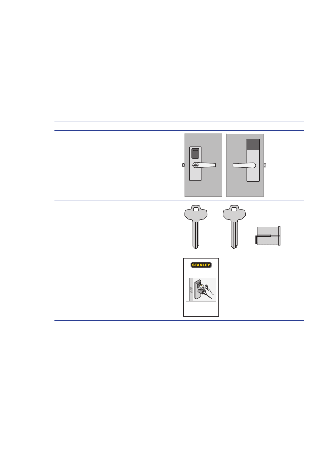
System Overview
Stanley includes two separate systems. The Wireless system combines powerful access
control software with Gateways and Wireless Locksets to allow complete lock control at the
door. This system allows remote access to any environment; no hardwiring is needed.
System Components
A Stand-Alone system has 3 components:
Component
1 Lockset
2 Core/Keyset
3 Proximity Cards
Exterior
Exterior
Extérieur
C
Operator Key
Operator Key
Operator Key
Temporary Operator Card
Place near reader to grant access
to factory default locksets.
125 kHz x 26 Bit
Interior
Interior
Intérieur
O
Core
Core
Core
Overview
8
Page 9
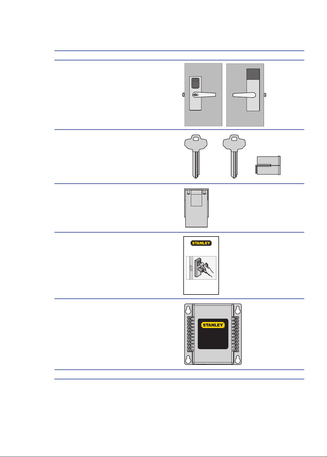
A Wireless system has 9 components:
Component
1 Lockset
2 Core/Keyset
3 Wireless Card
4 Proximity Cards
Exterior
Exterior
Extérieur
C
Operator Key
Operator Key
Operator Key
Temporary Operator Card
Place near reader to grant access
to factory default locksets.
125 kHz x 26 Bit
Interior
Interior
Intérieur
O
Core
Core
Core
5 Gateway
6 Stanley Intelli-M Software
9
Overview
This device complies with Part 15 of the FCC Rules.
Operation is subject to the following two
conditions: (1) this device may not cause harmful
interference, and (2) this device must accept any
interference received, including interference that
may cause undesired operation.
FCC ID: WEF-QZGW001
IC: 7713A-QZGW001
Model: QZGW001
Page 10
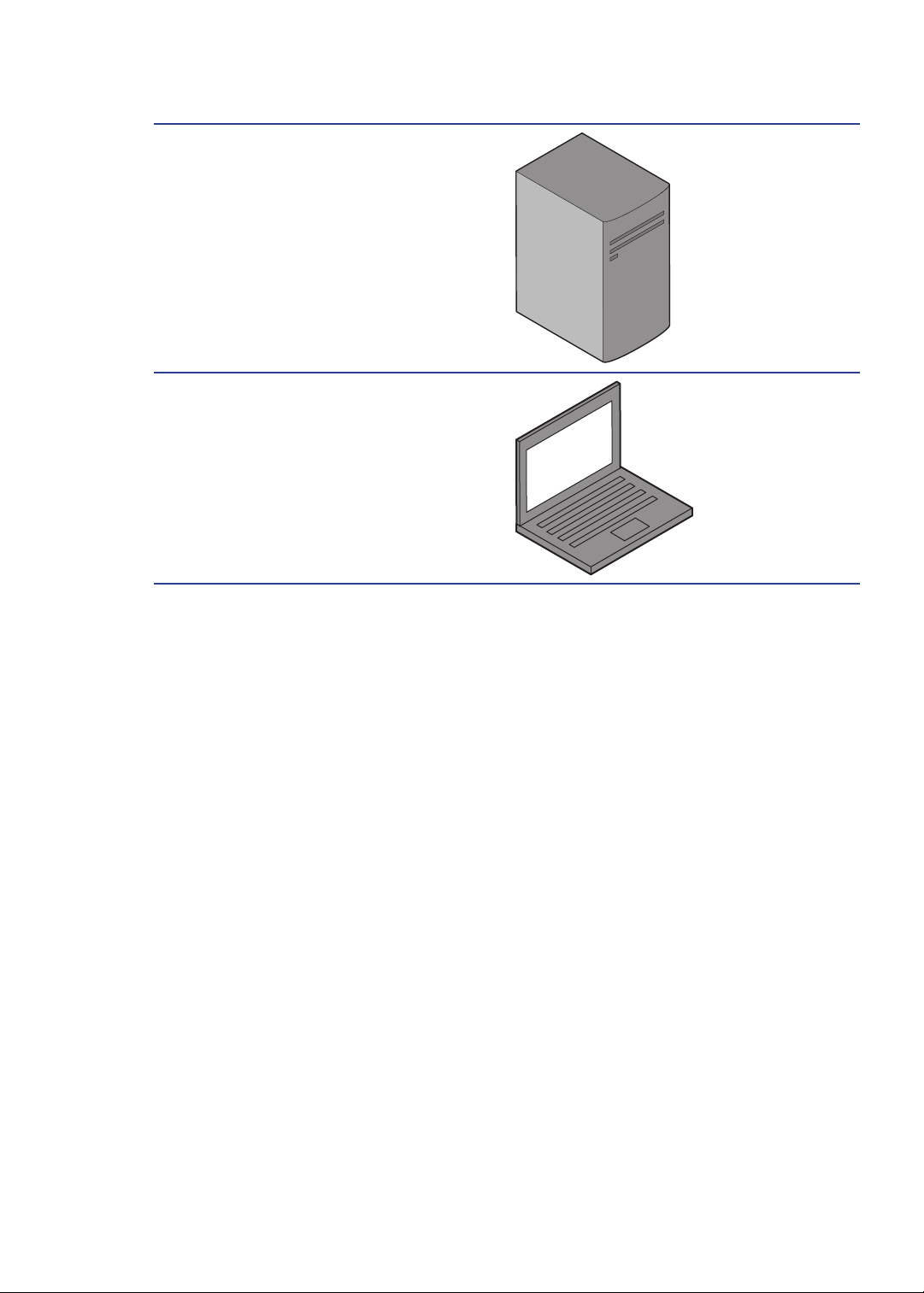
7 Host Computer
8 Mobile Device (optional)
Overview
10
Page 11

System Setup Steps
Standalone System:
Please see Chapter 2 for Standalone System setup instructions.
1 Install Standalone Locks
2 Standalone Management
Wireless system:
Please see Chapter 3 for Wireless System setup instructions.
1 Develop a Site Plan
2 Organize Segment Data
3 Prepare Host Computer
4 Install Software
5 Install Gateway(s)
6 Connect Gateway(s) to Lock(s)
7 Install Wireless Lock(s)
8 Understand Lockset Modes
9 Congure Software
11
Overview
Page 12

Overview
12
Page 13

Standalone System
2
Page 14

Needed Tools for Setup
Steps Tools
1 Install Standalone Lock(s) • Lockset Installation Instructions and
Template
• Tools listed in the installation instructions
and template
• Core/Keyset or Plastic Turn Piece/Core
• Temporary Operator Card
2 Standalone Management • Lockset(s) need(s) to be installed
• Core/Keyset or Plastic Thumb Core
• Temporary Operator Card
• Operator Card
• Shadow Card
Install Standalone Locksets
Steps
1 Check Installation Settings
2 Document Lockset Identication
3 Prepare Doors
4 Install Locksets
Check Installation Settings
Standalone Locksets are for use inside protected areas. For other applications (such
as outdoor use), contact the factory for the appropriate NEMA enclosure. Changes or
modications not expressly approved by Stanley Security Solutions could void the user’s
authority to operate the equipment.
Note Locks work within a temperature range of -31°F to 151°F. Extreme heat reduces
wireless signal strength and may cause a loss of connectivity.
Standalone System
18
Page 15
Document Lockset Identication
Record the MAC address and location of where you intend to install before lockset
installation to keep for your personal records.
Image of where the MAC address is located on the lockset
Prepare Doors
Use the template provided with the lockset package to prepare the installation. You can also
nd the template at www.stanley.com/templates.
Install Locksets
Use the installation instructions provided with the lockset package. You can also nd
installation instructions at www.stanley.com/installationinstructions.
Standalone Management
Steps
1 Key Lock/Unlock
2 Card Lock/Unlock
3 Basic Functionality
4 Add/Remove User(s)
5 Battery Functionality
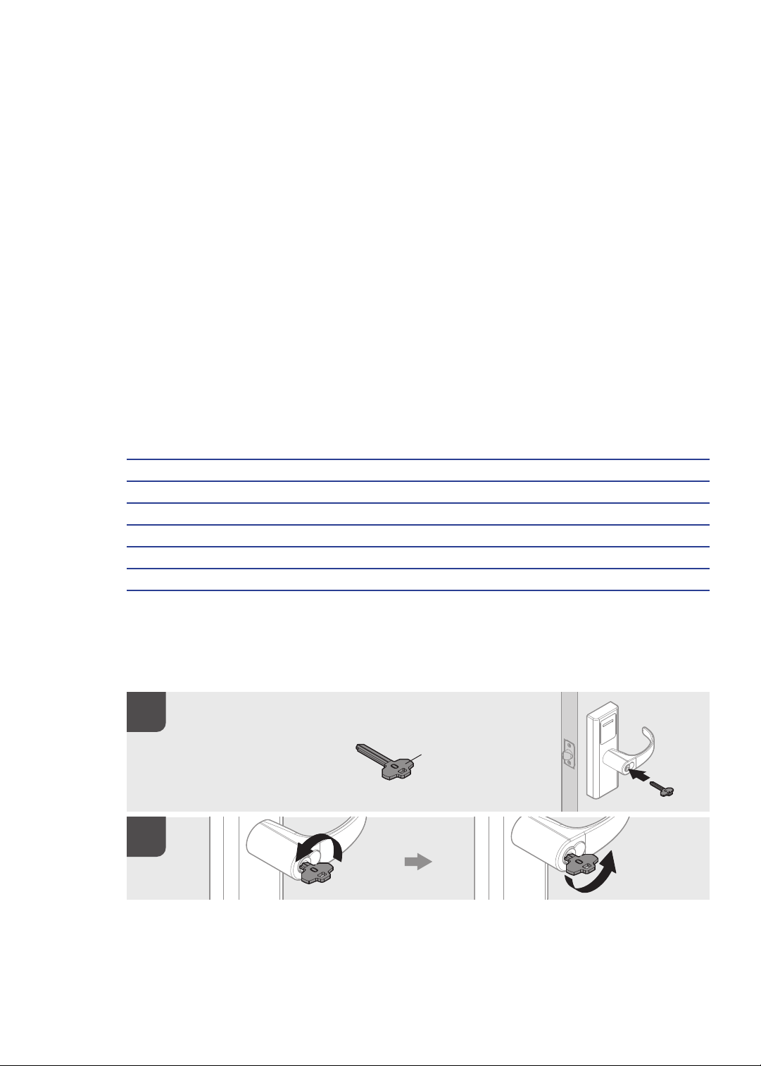
Key Lock/Unlock
Verify lockset operation by following these steps:
19
Insert the key
that is labled O.
Insert the key that
is labled O.
Insert the key that
is labled O.
Lock
Lock
Lock
Standalone System
Operator Key
Operator Key
Operator Key
Unlock
Unlock
Unlock
Page 16

Card Lock/Unlock
1 Present proximity card (do not present card a second time within two seconds).
2 If the lock contains this card data, a visual cue indicating “Single-scan Access Grant” will
occur, accompanied by an audio cue.
3 Lock will perform standard unlock sequence.
4 After a pause of ve seconds, the lock will perform a standard lock sequence.
Place Temp Card near reader to
grant access to factory default
locksets.
Place Temp Card near reader to grant
access to factory default locksets.
Place Temp Card near reader to grant
access to factory default locksets.
Basic Functionality
Passage Mode
1 Present a proximity card.
2 If ACL does not contain this card data, a visual cue indicating “Single-scan Access
Denied” will occur, accompanied by an audio cue.
Extended Passage Mode
1 Present proximity card twice in rapid succession.
2 If ACL contains this card data, lock will perform standard unlock sequence.
3 Lock will enter “Passage Mode,” accompanied by a visual cue.
4 If ACL does not contain this card data, a visual cue for “Double-scan Access Denied” will
occur, along with an audio cue.
Return to Normal Mode
1 Present proximity card once (do not present a second time within two seconds).
2 If ACL contains this card data, lock will perform standard lock sequence.
3 Lock will disable “Passage Mode” visual cue and return to normal operating mode.
Standalone System
20
Page 17

Add/Remove User(s)
Programing Mode
1 Inserts key, unlocks the lock, then re-locks the lock and unlocks it a second time (do this
within a ve-second window of time).
2 A visual cue for “Enter Programming Mode” will occur, along with an audio cue.
Programming Time Out
1 After putting lock in “Programming Mode,” if there is no proximity card interaction for 10
seconds, the activity will time out.
2 A “Leave Programming Mode” visual cue will occur, along with an audio cue.
3 Lock will return to normal operating mode.
Add User
1 While in “Programming Mode,” present the proximity card (do not present card a second
time within two seconds).
2 The card data will be added to the ACL as a normal operator.
3 A visual cue for “Card Added to Stand-Alone ACL” will occur, along with an audio cue.
4 Programming mode counter will reset to 10 seconds.
Remove User
1 While in “Programming Mode,” present the proximity card twice in rapid succession.
2 The card data will be removed from the ACL.
3 A visual cue for “Card Removed from Stand-Alone ACL” will occur, along with an audio
cue.
4 Programming mode counter will reset to 10 seconds.
Battery Functionality
Replace Battery
1 Open front panel and remove battery pack.
2 Insert new battery pack.
3 If battery power level is sufcient, lock will automatically power up and resume normal
functionality.
4 If installation is successful, any “Low Battery Mode” visual or audio cues will cease.
21
Standalone System
Page 18

Low Battery Warning
Both visual and audio “Low Battery Mode” cues will occur when battery power drops below a
specied level
Note At this point a normal load would last two weeks or less (i.e. 6%)
Standalone System
22
Page 19

23
Standalone System
Page 20

Standalone System
24
Page 21

25
Standalone System
Page 22

Standalone System
26
Page 23

27
Standalone System
Page 24

Standalone System
28
Page 25

29
Standalone System
Page 26

Standalone System
30
Page 27

31
Standalone System
Page 28

Standalone System
32
Page 29

33
Standalone System
Page 30

34
Page 31

35
Standalone System
Page 32

36
Page 33

37
Standalone System
Page 34

38
Page 35

39
Standalone System
Page 36

40
Page 37

41
Standalone System
Page 38

42
Page 39

43
Standalone System
Page 40

44
Page 41

45
Standalone System
Page 42

46
Page 43

47
Standalone System
Page 44

48
Page 45

49
Standalone System
Page 46

50
Page 47

51
Standalone System
Page 48

52
Page 49

53
Standalone System
Page 50

54
Page 51

55
Standalone System
Page 52

56
Page 53

57
Standalone System
Page 54

58
Page 55

59
Standalone System
Page 56

60
Page 57

61
Standalone System
Page 58

62
Page 59

63
Standalone System
Page 60

64
Page 61

65
Standalone System
Page 62

66
Page 63

67
Standalone System
Page 64

68
Page 65

69
Standalone System
Page 66

70
Page 67

71
Standalone System
Page 68

Wireless System
67
2
Page 69
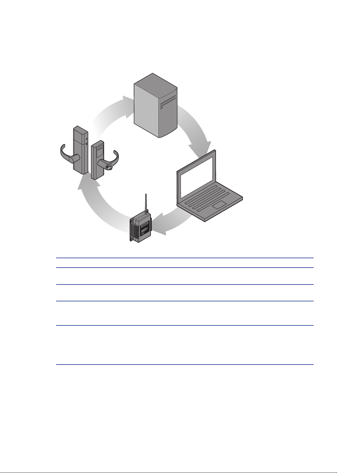
Components at Work for Wireless System
1
4
2
3
Components What It Does
1 Host Computer
2 Mobile device (optional)
3 Gateway
4 Wireless Lockset
PC running Stanley Intelli-M software and
gateway conguration for locksets
Mobile device running Stanley software and
gateway conguration for locksets
Connects to the Host Computer through a secure
IP address. Transfers data signals from Wireless
locksets to and from the Host Computer.
Battery-operated lockset equipped with Stanley
technology that controls user access at the door.
Communicates with the Gateway and grants user
requests according to how they are congured in
the Stanley software.
Wireless System
68
Page 70

Needed Tools for Setup
Steps Tools
1 Develop a Site Plan • Engineering drawings or segment map
• Stanley Technology Site Survey Kit
2 Organize Segment Data • MAC numbers for Gateway(s), Lockset(s),
and Wireless Card(s).
• Gateway(s) and lockset(s) names and
locations
3 Prepare Host Computer • 64-bit PC operating Windows 7
4 Install Software • Software Disc
• Software Quick Start Guide
5 Install Gateway(s) • Gateway Installation Instructions and
template
• Tools listed in the installation Instructions
and template
6 Gateway Conguration • Gateway Webpage
7 Install Wireless Lock(s) • Lockset Installation Instructions and
template
• Tools listed in the installation instructions
and template
• Core/Keyset or Plastic Thumb Core
• Wireless Card
• Temporary Operator Card
• Proximity cards and shadow cards
8 Understand Lockset Modes • Lockset Quick Start Guide
9 Congure Software • Software Disc
• Software Quick Start Guide
69
Wireless System
Page 71
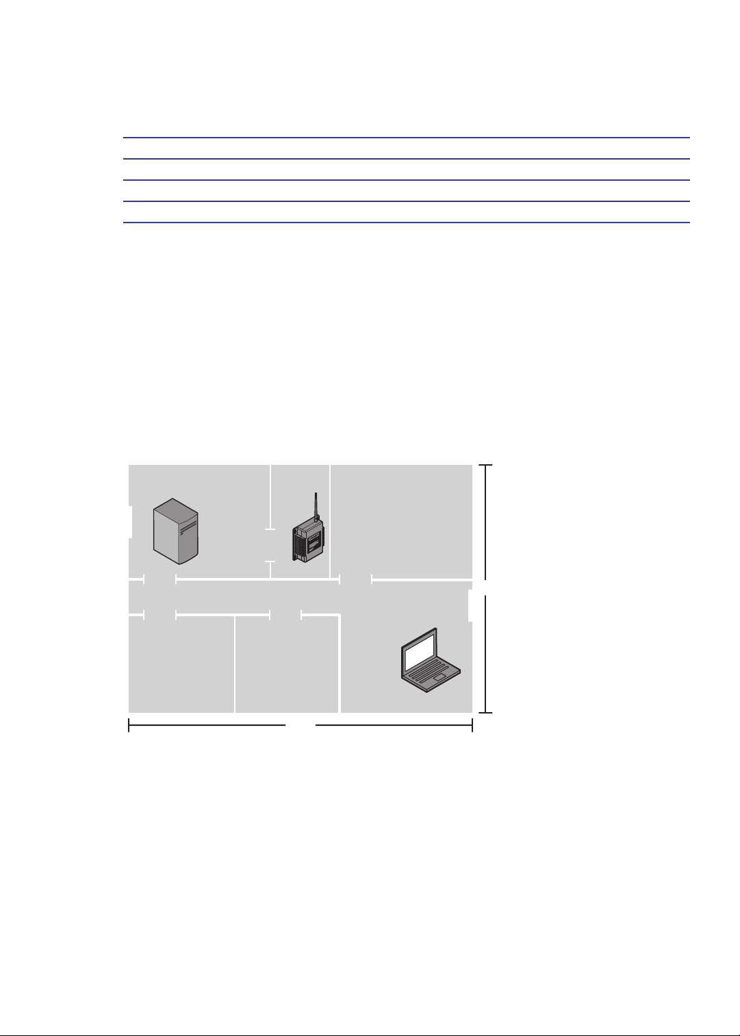
Develop a Site Plan
Steps
1 Gateway(s) placement
2 Document gateway and lockset identication
3 Position gateways
Gateway(s) Placement
Prior to any installation, a technician must perform a Stanley Site Survey using the Site
Survey Kit. You can nd the Site Survey Kit Quick Start Guide at www.stanley.com/
installationinstructions.
The technician may need you to make a site plan with building dimensions, distances
between buildings, possible obstruction, parking, and other gated access points prior to the
site survey. If one is not available through your facilities maintenance or project engineer,
visit the site to take measurements to create one.
Dentist Office
Host
Surgery Room Patient Room
Closet
Gateway
250 ft
Patient Room
Receptionist
150 ft
Typical Site
Configuration
Typical Site
Conguration
Typical Site
Conguration
Gateway Specications
The Gateway is a wireless device connected to the Host computer through a secure IP
address, similar to the way your computer is connected to the internet. It transfers data
signals from Wireless Locksets to and from the Host computer. The Gateway recognizes
all Wireless Locksets within its antenna range. One Gateway can control up to 64 Wireless
Locksets.
Wireless System
70
Page 72

Gateways provide bi-directional radio frequency communication between Wireless Locksets
and the associated host computer(s). All communications are via secure AES 128-Bit encrypted
2.4 HGz using spread spectrum RF Radio technology. The Gateway communicates to the host
computer through web services via either Ethernet 10/100 BaseT, or an approved commercial RF
carrier-enabling a wireless solution end-to-end.
Range
Transmit range from Gateway to lockset varies based on building construction and wi noise.
Site characteristics such as reinforced concrete walls could interfere or weaken the signal;
open spaces and low interference can increase signal strength.
Stanley transfers information between devices in the form of data packets over the 2.4
GHz ISM band. This band frequency is very heavily used in many devices such as wireless
computer networks (802.11 b and g) and cordless phones, which increases the risk of
lost packets, that is, packets that do not make it from a lockset to a Gateway because
of interference. Interference can also reduce lockset battery life due to the constant re-
broadcasting of packets and lost connections to the gateways.
To achieve maximum efciency in wireless system, the frequency range must be managed
effectively. Therefore, the installer must know the positions and channels of all the 2.4 GHz
wireless devices in the segment and ensure channels are assigned to each device so that
there is minimum frequency overlap with adjacent or nearby devices.
Extended Range
It is likely that you will have locations in your segment separated by distances greater than
300 feet. You may want to consider adding a Gateway to extend the transmit range or
purchasing a ceiling mount antenna.
Power Supply
Gateways must be located near lockset(s) and either two options:
1 Access to Ethernet 10/100 Base T network connection.
2 Access to a dedicated power source where they can recieve 24 VDC power from a AC to
DC transformer. Ensure that the gateway is plugged into a 24/7 power circuit that cannot
be turned off at a switch, such as a light switch that might be turned off by a cleaning
crew.
71
Wireless System
Page 73

Document Gateway and Lockset Identication
It is important to document the Gateway Media Access Control number (MAC address)
address, along with capacities and locations, and to give each device a common name (such
as “Patient Lobby”).
Image of where MAC address is located on gateway-TDB
Position Gateways
Position the Gateways for installation, using results from the Stanley Site Survey Kit. It is
important to perform the Site Survey process as many times as necessary to nd the strongest
position.
Note Test signal strength at all door locations near the edges of the coverage area, also at
any location where there may be physical interference.
Organize Segment Data
Steps
1 Collect Gateway and Lockset Information
2 Collect User Information
Collect Gateway Information
During your site survey, you have documented MAC numbers, names, capacities and
physical locations of all gateways and locksets so you can identify and assign them to the
correct location within the Stanley Intelli-M Software.
Collect User Information
You will need to gather the names of users, dene their access requirements, organize user
and timezone groups, and decide how to use other congurable features.
Create a table with information about each user, such as: User Type, User Group, Shift, etc.
Last First User Type Bldg. User
Group
Alverez Alicia Dentist A Admin Default
Bennet Ryan Sr. Technician A Basic Default
Ford Sara Technician A Basic Default
Lee James Receptionist A Basic Default
To organize your data, consider the following issues:
Timezone
Wireless System
72
Page 74

• What User Groups will help manage security?
• Are some shift workers are allowed on site only during specic days/hours?
• Are some areas ‘off limits’ to certain groups?
• Do some users need extra time to pass through a door (e.g. because of a food cart or
wheel chair)?
Prepare Host Computer
Steps
1 Ensure Correct Computer Settings
2 Stop Communication Server (if required)
3 Collect User Information
Note You must have administrative rights on your computer to perform many of the tasks
listed here.
Ensure Correct Computer Settings
Stanley software can be installed on the following server operating systems:
• Microsoft® Windows® Vista® Servers
• Microsoft Windows Server 2008
Vista Server Conguration
1 Power up the server.
2 Navigate the following path: Start > Control Panel > Programs >Turn Windows Features
On or Off > Internet Information > World Wide Web Services > Application Development
Features.
3 Select ASP.NET. The.NET Extensibility ISAPI Extensions and the ISAPI Filters options
will automatically be selected, as shown in Figure 3.
Image - TBD
4 Click OK.
5 Navigate the following path: Message Queue (MSMQ) Server > Microsoft Message
Queue (MSMQ) Server Core.
6 Select the MSMQ HTTP Support, MSMQ Triggers, and Multicasting Support options, as
shown in Figure 4.
Image - TBD
73
Wireless System
Page 75

7 Click OK. Close the window when the conguration process isdone.
8 Install the Stanley software by either downloading the Stanley software from www.
stanley.com.
9 Double-click the setup.exe application icon. Click “Run” to launch the installer.
10 Follow the screen prompts to create the Stanley database. When prompted, click Yes.
11 Following the system reboot, click “Run” to continue the installation. The system will
install the .NET Framework. This can take up to 30 minutes.
12 On the Database Server screen, identify the location for the Stanley database server
(refer to Figure 5).
13 Select “Yes…” to install a database server on thiscomputer.
14 Select “No…” to use an existing database server.
Image - TBD
Note If SQL has not been installed, Select “Yes…”When prompted, create a strong
database password. Enter a combination of upper case, lower case, and numbers.
Select “Complete” for the Setup Type. Click the “Install” button. Click “Finish” to close
the Stanley installer.
Windows Server 2008 Conguration
1 Power up the server.
2 Press the Ctrl+Alt+Delete keys, and enter the server password.
3 Navigate the following path: Start > Control Panel > Administrative Tools > Server
Manager.
4 Click “Add Roles” to display the Add a Roll section.
5 Go to the Web Server (IIS) section.
6 Click “Add A Required Feature” and click “Next.”
7 Go to the Application Development section.
8 Select “ASP.NET.”
9 Click “Add Required Role Services” and click “Next.”
10 Click the “Install” button.
11 Click “Features” to display the Features section.
12 Click “Add Features.”
13 Select “Message Queuing” and click “Next.”
14 Click the “Install” button.
Wireless System
74
Page 76

15 Exit the Conguration window.
16 Go to Installing The Intelli-M Access Software on page 18.
75
Wireless System
Page 77

Windows Server 2003 and XP Conguration
1 Power up the server.
2 Navigate the following path: Start > Settings > Control Panel.
3 Click “Add or Remove Programs.”
4 Click “Add/Remove Window Components” (which can be found onthe left-side margin).
The Windows Component window will be displayed.
5 Depending on the Operating System installed, select (i.e.,check mark) either “Application
Server” or “Message Queuing” along with “Accessories And Utilities.” Refer to Figure 6.
Then click “Next.”
Image - TBD
Wireless System
76
Page 78
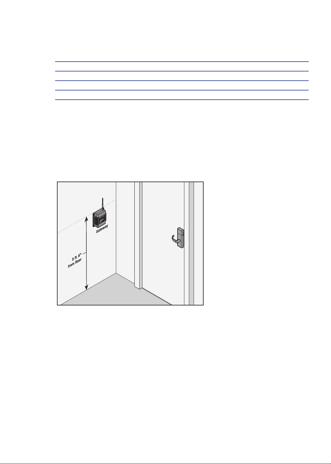
Install Gateways
Steps
1 Prepare Installation Area
2 Install Gateway
3 Verify Operation
Prepare Installation Area
The most common installation site is in a protected area such as a locked room or above
ceiling level.
Note If a protected area is not available, you may want to use a specially-designed locked
enclosure. Contact your dealer for more information.
Use the template provided with the Gateway package to prepare for installation. You can also
nd the template at www.stanley.com/templates.
Install Gateway
Use the installation instructions provided with the Gateway package. You can also nd
installation instructions at www.stanley.com/templates.
Verify Operation
Once your gateway has been connected, the gateway will verigy connection depending on
77
Wireless System
Page 79
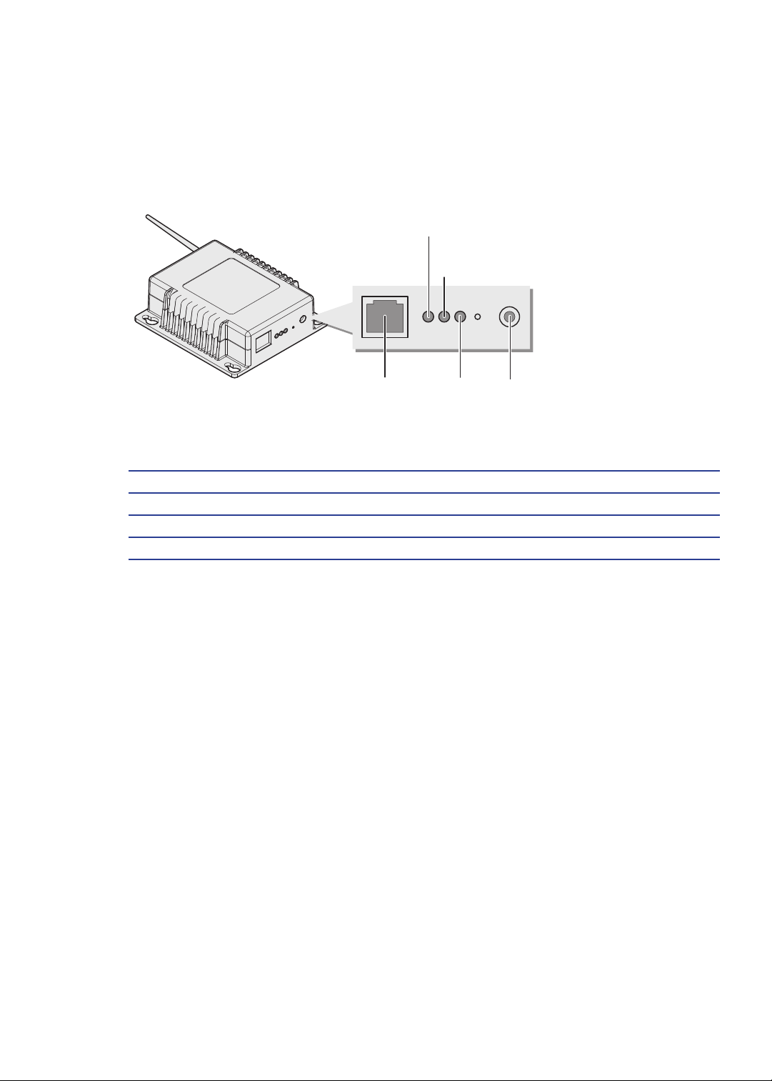
it’s power source and connection.
1 If you used a POE Cable only, the gateway leds will light blue and green.
2 If you used a AC to DC adaptor plus a cable, the gateway leds will light green only.
Power
Indicator
Link
Indicator
Gateway Conguration
Steps
1 Connect Gateway to Network
2 Congure IP Network Settings
3 Gateway Website
Connect Gateway to Network
Congure IP Network Settings
Gateway Website
Ethernet
Connection
Activity
Indicator
Power
Port
Wireless System
78
Page 80

Install Software
Steps
1 Install Software
1 Insert Stanley Intelli-M disc.
2 Double-click the setup.exe application icon.
3 Click “Run” to launch the installer.
4 Follow the screen prompts to create the Stanley Intelli-M database.
5 When prompted, click “Yes.”
6 Following the system reboot, click “Run” to continue the installation.
Note When prompted, create a strong database password. Enter a combination of upper
case, lower case, and numbers.
7 Select “Complete” for the Setup Type.
8 Click the “Install” button.
9 Click “Finish” to close the Intelli-M Access installer.
Install Wireless Locksets
Steps
1 Check Installation Settings
2 Document Lockset Identication
3 Prepare Doors
4 Install Wireless Locksets
5 Test Functionality
Check Installation Settings
Wireless Locksets are for use inside protected areas. For other applications (such as outdoor
use), contact the factory for the appropriate NEMA enclosure. Changes or modications not
expressly approved by Stanley Security Solutions could void the user’s authority to operate
the equipment. Make sure to check temperature. Stanley locks will work from -31°F to 151°F.
Note Locks work within a temperature range of -31°F to 151°F. Extreme heat reduces
wireless signal strength and may cause a loss of connectivity.
79
Wireless System
Page 81
Document Lockset Identication
Record the MAC address before installing device – you will need this when conguring the
lockset.
Prepare Doors
Use the template provided with the lockset package to prepare the installation. You can also
nd the template at www.stanley.com/templates.
Install Wireless Locksets
Use the installation instructions provided with the lockset hardware. You can also nd
installation instructions at www.stanley.com/installationinstructions.
Test Functionality
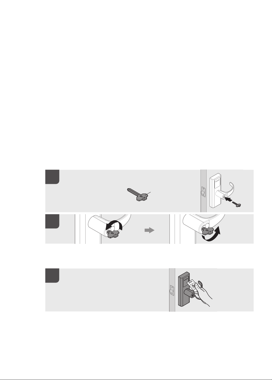
Verify lockset operation by following these steps:
Insert the key
that is labled O.
Insert the key that
is labled O.
Insert the key that
is labled O.
Lock
Lock
Lock
Operator Key
Operator Key
Operator Key
Or use a Temporary Operator Card to test functionality
Place Temp Card near reader to
grant access to factory default
locksets.
Place Temp Card near reader to grant
access to factory default locksets.
Place Temp Card near reader to grant
access to factory default locksets.
Unlock
Unlock
Unlock
Wireless System
80
Page 82

Congure Software
Steps
1 Terms and Concepts
2 Door Behavior
3 Rules and Privileges
4 Schedules and Holiday Sets
5 Events and Alarms
6 Alarm Acknowledgement
7 Extensibility and Peripherals
8 Quick Setup
9 Create Doors
10 Create a Person
11 Create an Access Privilege
12 Licensing Your System
Terms and Concepts
Door vs. Zone
Image - TBD
The Door occupies a physical space, and its border areas are called Zones. When applying
privileges to a Door you’re granting access to a Zone.
Upon installation, Intelli-M creates two default Zones: Inside and Outside. In general, they
represent the inside of your building or ofce and the outside of your building or ofce.
Inside the building you may want secure interior doors . Each secured door also borders two
Zones: the interior of the oor/building and the space you wish to secure. You may re-use the
Inside Zone for the unsecured side of the door and create a new Zone, (e.g. Dental Records
Room) to serve as the name of the secured space. When conguring access privileges, you
will grant access to the Dental Records Room Zone, not the Door that borders it.
You can re-use Zones in more than one way.
1 One way is to re-use the Inside Zone because it represents the same physical space as
your perimeter doors (see example above).
2 Another opportunity to re-use a Zone name is when the same people will always have
identical access privileges to multiple areas. For example, if a dentist ofce has three
patient rooms and the same people always have identical access to these rooms, you
can create a single Zone (e.g. Patient Rooms) to represent this entire space.
81
Wireless System
Page 83

Muster Zone
Image - TBD
A Muster Zone is a Zone tagged with ‘In Muster’ or ‘Out Muster’. When you tag a Zone with
‘In Muster’, Intelli-M will track all users who enter that Zone. You can also tag a Zone with
‘Out Muster’ to track both sides of a Door.
A special Muster View on the Events Page displays the location of all cardholders in these
Muster Zones in real-time.
Cardholder vs. Group
Image - TBD
Stanley Intelli-M denes a cardholder and congures the cardholder’s access rights. It
also puts the Cardholder into a Group, similar to how Windows has Users and Groups. All
cardholders must be a member of one Group, and can be a member of multiple Groups.
Access Privileges are applied to Groups, not individual Cardholders. Therefore you can
modify the access privileges of a large number of Cardholders with one conguration
change. You can also change access privileges for a Cardholder by adding/removing them
from a Group.
Door Types
Image - TBD
A Door Type is a template that describes the input and output conguration gathered into a
single unit. Intelli-M installs several default Door Types.
Most or all your Doors’ wiring conguration is already described in one of the default Door
Types, but if you have Doors with atypical needs, you can create your own Door Type.
Door Behavior
Door Behavior declares the Door’s unlock schedule and the mode of the attached card
reader(s), such as “Card Only” mode or “Card plus PIN” mode.
Stanley Intelli-M creates one behavior by default: the “Always Locked” Behavior. This
Behavior sets the card reader to “Card plus PIN”. This single behavior covers the typical
operating procedures for most of your doors.
Wireless System
82
Page 84

Rules and Privileges
Image - TBD
Privilege is the combination of a Group (who has access), a Zone (where is access granted),
and a Schedule (when is access granted). You can create as many Privileges as desired.
A Rule is “what to do when something happens.” For example, a Privilege is a type of a Rule
(i.e. “what to do when a card is swiped or a PIN is entered”). Other examples include sending
emails, locking and unlocking any Zone or Door, and energizing or de-energizing one of the
Door’s outputs. (See more information in Advanced Setup and Conguration.)
Schedules and Holiday Sets
Image - TBD
A Schedule is a stand-alone time range that denes a seven-day week. Each day has a set
of zero or more time ranges that you dene.
Active Time Range is displayed in blue. Inactive Time Range is displayed in white.
This Schedule can be applied to a Door (via Door Behavior) as an unlock schedule; to a
Person (via Group membership) to dene the hours they may access a Zone; or to a Rule to
dene when it may be active.
For example, when a Schedule is applied to a Door, the Door will be unlocked during the
Active Time Range (blue section), and unlocked during the Inactive Time Range (white
section).
A Holiday is a single day in which normal business hours are altered, such as Thanksgiving
or Christmas.
A Holiday Set is a grouping of Holidays in which the altered business hours match.
For example, a Holiday Set might consist of New Year’s, Thanksgiving, the day after
Thanksgiving, and Christmas Day, when the ofce is closed.
Another Holiday Set might consist of Christmas Eve and New Year’s Eve because the ofce
hours are a half day.
Once you’ve established your Holiday Set, you can assign a set of zero or more time ranges
that dene that Holiday Set. You can then apply that Holiday Set to a Schedule you’ve
created.
You can assign a complex Schedule to any Door Behavior, Person Group, or Rule.
83
Wireless System
Page 85

Events and Alarms
By default, Stanley Intelli-M identies an Alarm as the usual access denial events, but you
can custom an Alarm using the Rules Engine. (See more information in Advanced Setup and
Conguration.)
Alarm Acknowledgement
Image - TBD
Automatic Alarm Acknowledgement allows you determine which events are important.
Extensibility and Peripherals
Image - TBD
A Peripheral is a third-party device that can be plugged into the Intelli-M Rule Engine
allowing integration.
• A Peripheral can be:
• a video surveillance DVR
• an individual IP Camera
• a hardware I/O device
• a web service like Google Maps
Each Peripheral is supported by a Plugin, which is a software module which provides the
bridge between Intelli-M and the third party device/service.
Use the Rules Engine to control the Peripheral. For example, you may instruct it to:
• “Record video on camera X when a card with invalid credentials are swiped at Door Y”
• “Energize output A when input B is raised”
• “Show live video in my browser on camera X when even Y occurs”.
Intelli-M provides one Peripheral by default: a 32 channel ethernet-controlled I/O device.
You can create a Rule to force the device’s outputs to a desired state, or use the device’s
inputs states to lock or unlock doors, send emails, etc.
Reports
Image - TBD
Stanley Intelli-M utilizes Microsoft’s Reporting Services engine and its tools, allowing you to
customize your reports.
Wireless System
84
Page 86

Custom-printed cardholder’s badges also utilize the Reporting Services Engine, giving you
complete control over badge design.
Quick Setup
Follow these simple steps to get your access control up and running in minutes.
Steps
1 Login to Stanley
2 Click All Programs
3 Click Stanley to launch web browser, which will point to the TBD, running under IIS.
You will be presented with a login screen.
4 Use default username, which is admin. The default password is admin. Later in this
chapter you will learn how to change the default password.
Image-TBD
Create a Door
1 Log into the system.
2 Press ‘Conguration’ in upper right corner.. The main page in this section is the Doors
Page.
3 Click the ‘Create Doors’ in Action pane on left side of window. A pop-up window will
appear as shown in Figure XX.
Image-TBD
Choose a Door Name
1 Choose appropriate name (e.g. Front Door, Lobby Door).
2 Click the IP Address or Serial Number combo boxes to nd the IP address of your main
doo r.
Image-TBD
Choose a Door Type
If your door has a contact to detect the open/close status of the door, choose door type listed
as “1 or 2 Reader IN1 Normally Closed”
If your door does not have this contact, choose door type listed as “1 or 2 Reader IN1
Normally Open”
Image-TBD
85
Wireless System
Page 87

Choose a Door Behavior
We recommend “Always Locked” as the default behavior.
Image-TBD
Selecting two Zones which Border the Doors
1 The upper two combo boxes tell the system which two Zones the Door borders. The
lower two combo boxes tell the system which Zones have card reader access.
2 Choose “Outside” and “Inside” for the top two combo boxes.
3 Choose “Inside” for Card Reader One (to grant access to the “Inside” Zone).
4 Choose the proper Zone for Card Reader Two.
Note If you have no second reader, it doesn’t matter which Zone you choose. If you have
two readers and both on the outside, choose “Inside” for Card Reader Two.
Image-TBD
Choose a Time Zone
1 Choose the time zone in which the controller is physically located. (For most installations
this is the currently selected time zone.)
2 Press ‘Create’ and wait a few seconds.
3 The Door will appear in the main Doors viewing area.
4 Three status icons will appear next – the left-most icon will be a yellow triangle.
5 In the icon legend (lower left part of the window) a yellow triangle means the Door’s
conguration has changed and needs to be updated. (This is normal for the rst-time
creation of the Door.)
6 If the icon is a red circle, the system could not communicate with the Door using the
information you provided. If this occurs, please refer to the Troubleshooting section at the
end of this document.
Note If you create or update a Door and you see a red wavy line in a eld, hover the
cursor over that eld and a message will appear explaining the problem. Correct the
problem and try again.
7 Repeat these steps to create additional Doors.
8 When nished, click ‘Update All Doors’ in the Actions menu on the left side of the
window.
Wireless System
86
Page 88

Note At any time you can click on one or more Doors and click the ‘Update’ Action link to
update specic Doors.
Image-TBD
Create a Person (Add a User)
1 Click ‘Home’ in upper left part of window to go back to Events Page.
Image-TBD
Note These two links, ‘Home’ and ‘Conguration’, take you back and forth between normal
operating mode and conguration mode.
2 Click on the ‘People’ tab to start adding people.
Image-TBD
3 You may stay in the ‘Conguration’ section by clicking on ‘Groups’, then clicking on
‘Person View’ under the Views menu in left part of window.
Image-TBD
Note The People Page displays all the Cardholders and Users in the system. (Right now
there is likely only one User – Admin – the account you’re currently using.)
Image-TBD
4 Click ‘Create Person’ in the Actions menu. A pop-up window will appear as shown in
Figure XX.
Image-TBD
5 Enter a First Name and Last Name in the appropriate name elds.
Image-TBD
6 Enter a Site Code and a Card Code.
Image-TBD
Note The Card Code is printed on the card and the Site Code is printed in the paperwork
that came with the cards.
Image-TBD
7 If you do not know the Card Code or Site Code, simply swipe the card at the Door you
created earlier and the Site Code/Card Code will display on the Events Page. Copy these
codes into the two elds.
87
Wireless System
Page 89

Image-TBD
8 Place the Person in a Group.
Image-TBD
9 Click the arrow in the Groups tag (or drag & drop) to add a name to the selected Group
(visible below the Card Code boxes).
Image-TBD
10 A list of Group names will slide from the left, exposing the only existing Group
(‘Everyone’).
Image-TBD
Note To easily nd a Group name in a long list of Groups, click the mouse anywhere in the
Available Groups window and start typing the name of the Group. The name most
closely matching will automatically select.
11 Repeat these steps to create each additional Person.
12 Each time you create/update a Person or prole, the information will be automatically
sent to each Door – there is no need to perform a Door Update Action.
Image-TBD
Note If you create or update a Person and you see a red wavy line in a eld, hover the
cursor over that eld and a message will appear explaining the problem. Correct the
problem and try again.
13 Change the Admin password.
14 Select the Admin rectangle.
15 Click ‘Edit Person’ in the Actions menu. A pop-up window will appear displaying the
Admin information, as shown in Figure XX.
Image-TBD
16 Click ‘Role’ to modify Admin user’s credentials.
17 Provide a new Password in both Password elds.
18 Click ‘Save’.
19 You will automatically log out. You may log back in using the new Password.
Create an Access Privilege
1 Click on ‘Conguration’.
Image-TBD
Wireless System
88
Page 90

Note If you are already in the Conguration section, just click ‘Rules’. The Rules Page will
appear showing a list of default Rules.
2 Select ‘Rules’.
Image-TBD
3 Simply click the Rules tab if you are already in the Conguration section. The Rules
Page will appear showing a list of default Rules.
Image-TBD
4 Click the ‘Create Rule’ Action link in the Actions menu. A ‘Create Rule’ pop-up window
will appear as shown in Figure XX.
Image-TBD
5 The default Rule ‘Access Privilege’ will be selected – you do not need to change the
combo box.
Image-TBD
6 Choose a Schedule.
Image-TBD
7 Choose the ‘Everyone’ Group. (Remember, the Person/People you created earlier belong
to this Group.)
Image-TBD
8 Choose a Zone.
9 Choose the ‘Inside’ Zone. (Remember the perimeter Doors you created have their card
readers providing access to the ‘Inside’ Zone.)
Image-TBD
10 Click the ‘Create’ button to save your new Access Privilege.
11 Click the Doors tab again.
12 The new Door/Doors have a yellow triangle which means the conguration has changed
and an update is needed.
13 Click ‘Update’ or ‘Update All’ Action link to update the Doors.
Image-TBD
14 The Doors are now locked and secured, granting access to the cardholders you created.
89
Wireless System
Page 91

Licensing Your System
1 Click on ‘Conguration’.
Image-TBD
2 Click on the ‘System Settings’ link (in the upper right corner of the window). A popup
window will appear, as shown in Figure XX.
Image-TBD
3 You’ll see the Intelli-M version number along with the trial license key and other
information. Enter the key you received when you purchased the product and the system
will automatically be licensed.
Wireless System
90
Page 92

91
Wireless System
Page 93

Wireless System
92
Page 94

93
Wireless System
Page 95

Wireless System
94
Page 96

95
Wireless System
Page 97

Wireless System
96
Page 98

97
Wireless System
Page 99

Wireless System
98
Page 100

99
Wireless System
 Loading...