

dormakaba USA SDC2K Users Manual
Adding a New User Fields Category
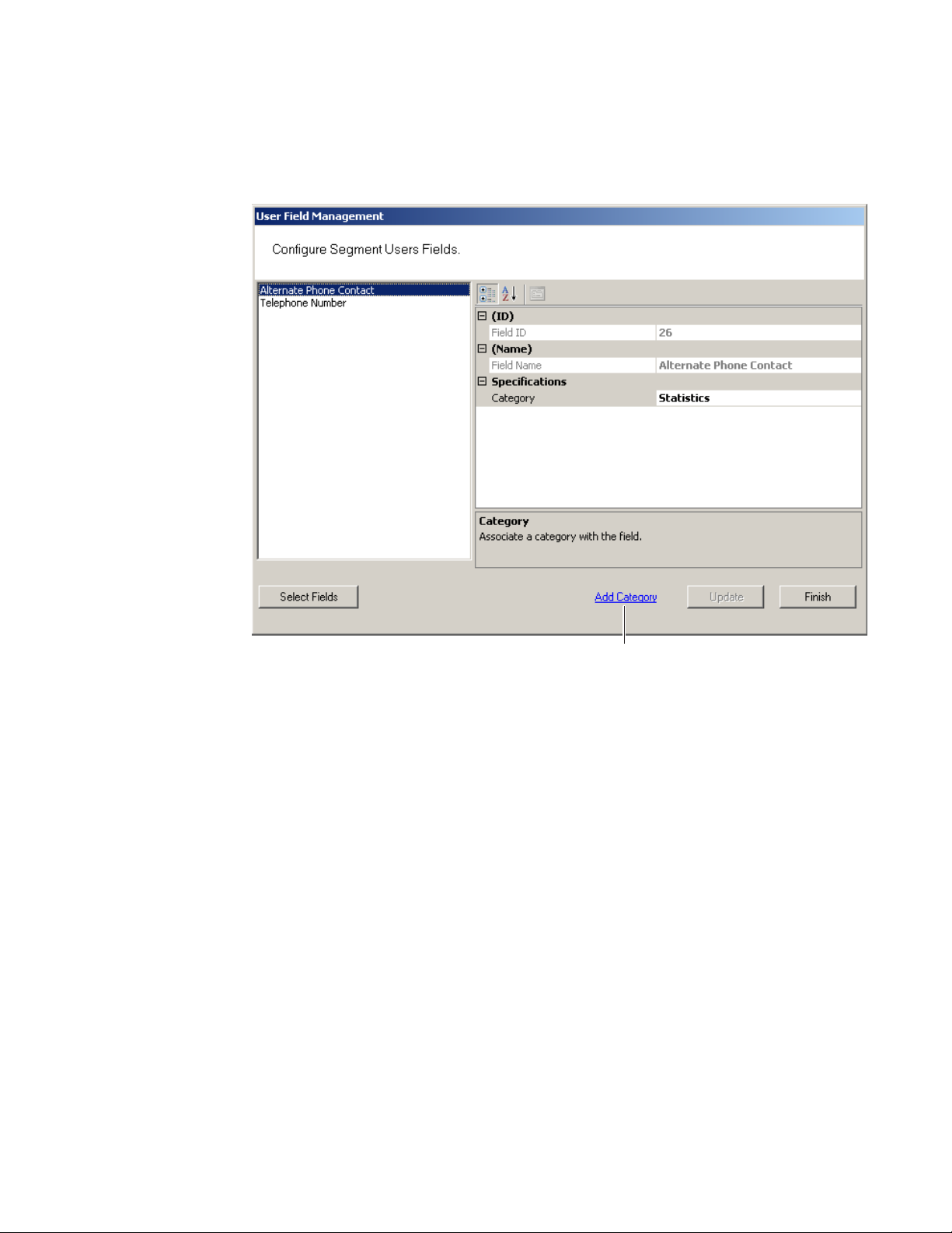
1 In the User Field Management of Segment dialog box, click the Add Category
Link at the bottom of the dialog box.
Figure 71 Add Category
Add Category
2 The Add and Remove System User Categories window opens.
101
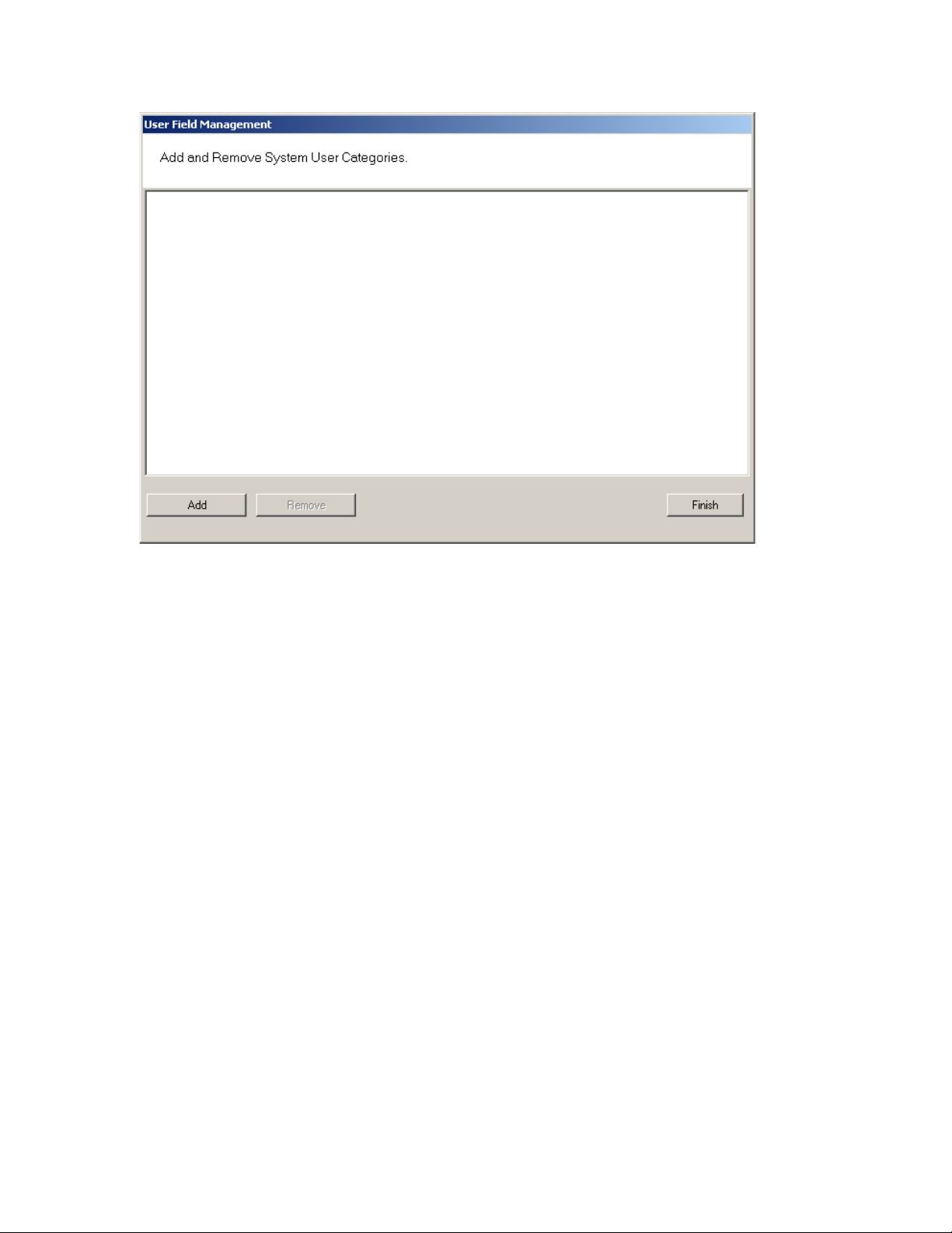
Figure 72 Adding and Remove System User Categories
3 Click the Add button. “Category 1” appears in the text box.
4 Double-click on “Category 1” to rename it.
5 Click Finish. In the Configure Segment Users Fields dialog box, the new cat-
egory is now available for selection from the Category drop-down list. Now you
can select this category when defining a new User Field.
102

Removing User Fields and Categories
You can also remove added User Fields and Categories from the system. The system will not allow you to do this, however, if the field or category is in use. Before
you remove the field or category, ensure there are no records assigned to them,
then perform the following steps.
To remove User Fields from the system
1 In the User Fields Management dialog box, click the Select Fields button at the
bottom of the dialog box.
2 From the User Fields in Facility list on the left, select the fields you wish to re-
move and click Remove>>. The field is moved to the User Fields list on the right,
and remains inactive unless you add it back to the list.
3 Click Finish. The field is no longer available in the User Fields list.
To remove added Categories from the system
1 In the User Field Management window, select Add Category.
2 The Add and Remove System User Category window opens.
3 Select the category you wish to remove, and click Remove. Click Finish when
you are done.
User Groups
User Groups are a convenient way to define properties that will affect certain
groups of individuals in your system. For example, if your Administrative personnel
have different hours or entry parameters, you can create an Administrative group,
make that group a Timezone Group and assign administrative personnel to that
group.
You can define any number of User Groups, such as Administrative, General, Laboratories, Dormitories, Night Shift, Contractors, and so on.
Adding User Groups
1 In the Users Tab, Associations category, click the User Groups field. Select
the ellipsis button at the far right of the field. The User Group Setup dialog box
opens.
103
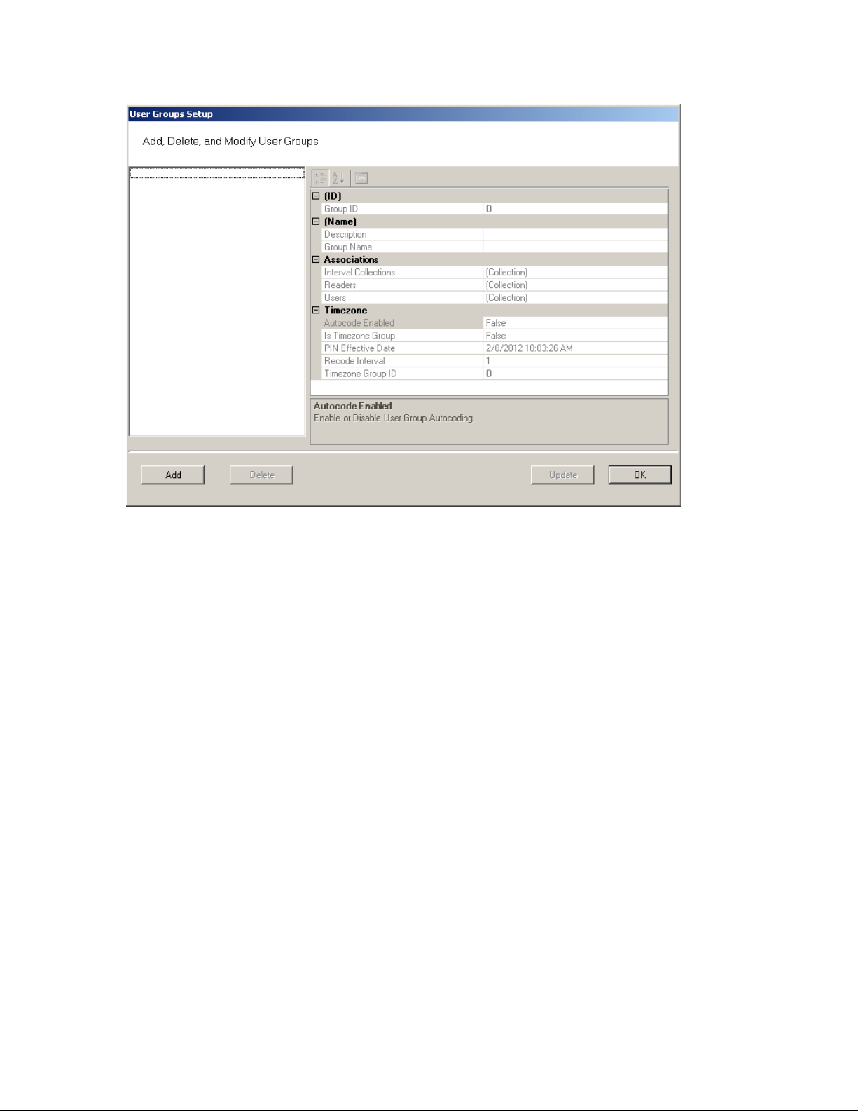
Figure 73 User Groups Setup
2 The groups you create display on the left. The group’s ID, Name, Associations
and Timezone appear on the right.
3 Select Add. A new Group (Group1) is created and displays on the left.
4 In the Group Name box, replace the name Group1 with a name for the new
group (for example, Administrative).
5 Select OK.
Note Once you have added users to the system via the Users Tab, you can assign them
to these User Groups.
Removing User Groups
In the User Group Setup dialog box, select the group you wish to remove and select the Delete button. The group is immediately removed from the list, along with
its associations.
Associating Users with User Groups
1 In the Segment Tab, Associations category, click the User Groups field.
104
2 Select the ellipsis button at the far right of the field.
3 In the User Groups Setup dialog box, select the group you wish to associate
with users.
4 In the Associations category, click in the Users field and select the ellipsis but-
ton. The Users of Group dialog box opens.
5 All users in the segment not already assigned to the group are displayed under
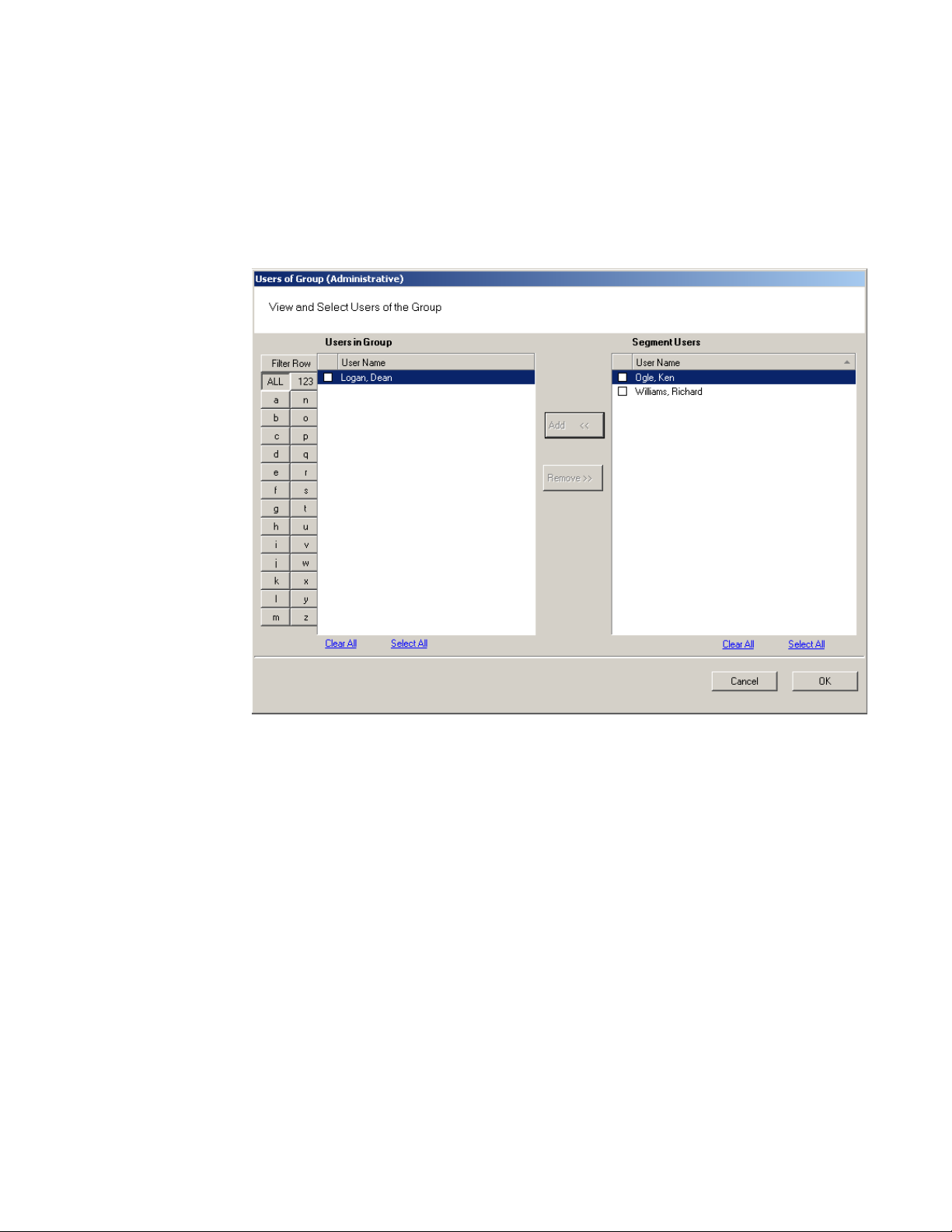
Segment Users list on the right.
Figure 74 Users of Group
Note Users will not appear in the Segment Users list until they have been added to the
system. If you have a large number of users, you can use the Alphabetic sorter
buttons on the left of the list to more quickly find a specific user.
6 Select the checkbox next to the users you wish to associate with the User
Group.
7 Select <<Add. The User names will be removed from the Segment Users list on
the right and display under Users in Group list on the left.
8 Select OK to close the Users of Group dialog box.
105

Removing Users from User Group
1 In the User Groups Setup dialog box, select the group in which the user cur-
rently resides.
2 In the Associations category, click on the Users field, and select the ellipsis
button. The Users of Group dialog box opens.
3 From the Users in Group list on the left, select the checkbox next to the user
you wish to remove from the group.
4 Select Remove. The user name will be removed from Users in Group list on the
left and moved back to the Segment Users list on the right. Select OK to close
the Users of Group dialog box.
Timezone User Groups
You can create up to 512 Timezone User Groups to further define access levels for
the Master Timezone. These can restrict access of a certain group of employees
to a specific time period. Perform the following steps to create a timezone user
group.
1 In the Segment Tab, select the Segment to which you wish to add a new Time-
zone User Group.
2 In the Associations Category, select User Groups and click the ellipsis button at
the far right of the field. The User Groups Setup dialog box opens.
106
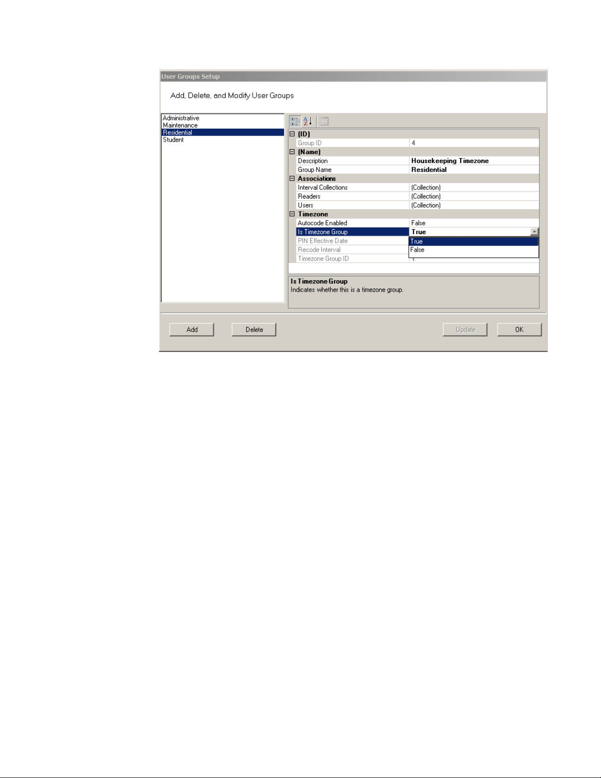
Figure 75 Creating a Timezone User Group
3 Select Add. Group1 is created.
4 In the Name Category, Description, enter a description for the group, for ex-
ample: Housekeeping Timezone.
5 In the Group Name, replace Group1 with the name of your new user group, for
example, Residential.
6 Under Timezone, change the Is Timezone Group default setting from False to
True. Select Update to continue creating groups.
7 Select OK to save the new Timezone group.
Once you have created a Timezone group, you will need to set up access times
to apply to that group. For more information about Timezones and Timezone User
Groups, see “Configuring Timezones” on page 137.
107

Credential Settings
Keypad credentials, magnetic card settings, and proximity card settings are all set in
this category. Detailed steps are presented in the following sections.
Keypad Credential Length
If your access system will have or currently has cards encoded with keypad credentials, you may set the number of digits required here.
Note Keypad credential length must be set before you add users to the system.
Perform the following steps to set the Keypad Credential Length.
1 In the Segment Tab, under the Credential Settings category, click in the Keypad
Credential Length field.
2 Click the ellipsis button at the far right of the field. The Set value of Keypad
Credential Length dialog box opens.
Figure 76 Setting the Credential Length
3 Enter the length or slide the bar to select the position of the Keypad Credential
length you will use on segment cards.
4 Select OK to save your settings and exit the box.
Magnetic Stripe Credential Configurations
Before Magnetic cards can be used in the system, you must configure AMS to
accept the card types and settings. Figure 77 shows the Magnetic Stripe Credential
Configurations Window. Default settings will be sufficient for most systems.
Most users will use Track 2 cards and will not need to set up any type of advanced
card parameters. Wi-Q AMS default Expiration Date, Segment Code, and Issue
Number settings to Not Used, and no other changes need to be made.
Stanley Security Solutions currently stocks and provides Track 2 or Track 3
magnetic cards. These cards conform to ISO standards and can be ordered preencoded or blank. The system can be used with either Track 1, Track 2, or 3 cards,
however you can only encode 1 type within the same segment.
108
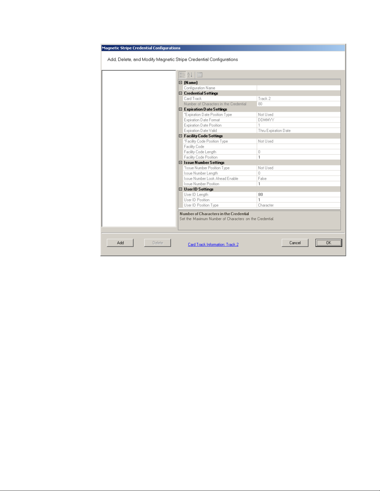
Figure 77 Magnetic Stripe Credential Configurations
If you must make changes to the default settings, click Add to create a new
Magnetic Stripe card configuration, and give a name to your configuration in the
Configuration name field.
109

Credential Settings
Wi-Q AMS can be configured to accept coding from existing Track 1(210 BPI),
Track 2 (75 BPI) or Track 3 (210 BPI) cards as long as the code does not exceed the
maximum number of characters for that track and/or controller. Magnetic cards
are configured as Track 2 by default. Perform the following steps to change to
change the segment track setting for encoding cards:
1 In the Magnetic Stripe Credential Configurations window, click the Card Track
Information link at the bottom of the window.
2 The Define Magnetic Stripe Card Track Information window opens. Specify the
desired track from the dropdown menu. Then click Finish.
3 Click OK to exit the Magnetic Stripe Credential Configurations window.
4 In the Segment tab, click Update at the bottom right to update your segment.
Card Track Limits
Wi-Q AMS is flexible and may accept coding from existing Track 2 or Track 3
cards as long as they do not exceed the maximum number of characters for that
track and/or controller. These characters include any digits and field separators,
however they exclude the starting and ending sentinels. Refer to the Stanley
Security Knowledge Base or contact Technical Support for controller hardware
track limits.
110

Character codes and counts
;
The software recognizes data on a magnetic card stripe using ANSI standard
codes formatted to either a field separator or character count. Following is a brief
description of each type.
Field Separator — Field Separator (FS) character, generally represented as an
equal sign (=) to separate two independent data fields. A card using this method
might have the owner’s individual ID encoded at the beginning of the stripe followed by the FS character then the global segment ID. The fields can be in either
order, or there can be more than two fields, which could be required for compatibility with pre-existing systems, and any one of them can be set up as User ID,
Segment ID, Card Issue ID, or Expiration Date.
Following is an example of encoded data using field separators on Track 2.
Figure 78 Data Fields
1576=3492657182=0=060113
FIELD 3: Card Issue ID
0 = First Issue
FIELD 2: User ID Number (Max 19 digits)
ID Number = 3492657182
FIELD 1: Facility Code = 1576
FIELD 4: Card Expiration Date
060113 = MMDDYY = June 1, 2013
111

Character Count — You can set up a character count from the beginning of each
;
Facility Code = 1576
ID. For example, the Segment ID could start at the beginning of the data stripe,
digit count of 1. If the Segment ID has eight digits, the User ID would be set to
start at digit count of 9. This method requires all data groups with exception of the
last one, to have a fixed number of digits. Following is an example of encoded data
using character counts on Track 2.
Figure 79 Character count fields
157634926571820060113
Card Expiration Date Starts at Character 16
060113 = MMDDYY = June 1, 2013
Card Issue ID Starts at Character 15
0 = First Issue
User ID Number Starts at Character 5
ID Number = 3492657182
Facility Code Starts at Character 1
Note If you are not using the default settings for Magnetic Stripe Credential
Configurations, make sure that Expiration Date Position Type, Facility Code
Position Type, Issue Number Position Type and User ID Position Type are all set to
either must be set to “Field” (Field Separator) or “Character” (Character Count);
you cannot mix types.
112

Expiration Date Settings
Perform the following steps to define a card expiration date.
1 In the Magnetic Stripe Credential Configurations window, under the Expiration
Date Settings category, click in the Expiration Date Position Type field.
2 Select either Character or Field from the drop-down list. The Expiration Date
Format, Position and Valid list boxes activate.
3 In the field next to Expiration Date Format, select the date format you need
from the drop down list (MMDDYY, etc.).
4 In the field next to Expiration Date Position, enter the value to represent either
the field position or the character number where the expiration date appears
on the card stripe.
5 In the field next to Expiration Date Valid, select either To or Thru Expiration
date.
6 Select OK to save your settings and exit the box.
Note If you use the character code format and select the six-digit expiration date
format, the value of your next setting (Facility Code Settings) must start with
character position 7. If you enter an incorrect value, the system will report an error
message. Review the “Character codes and counts” on page 111 if you need
clarification.
Facility Code Settings
Perform the following steps to define a facility code type, position and length.
1 Under the Facility Code Settings category, click in the Facility Code Position
Type field.
2 Select either Character or Field from the drop-down list. The Facility Code
fields below activate.
3 In the field next to Facility Code, enter your Facility Code number.
4 In the field next to the Facility Code Length, enter the length.
5 In the field next to Facility Code Position, enter the facility code position.
6 Select OK to save your settings and exit the box.
113

Issue Number Settings
You can issue a replacement card to a user in lieu of issuing a new User ID. The
Card Issue ID consists of one or two digits from 0 through 99. After using the card
with an incremented (higher number) Card Issue ID in a reader, that lock will no
longer accept cards with the same User ID that have a lower Card Issue ID.
Perform the following steps to define an issue number position.
1 In the Issue Number Settings category, click in the Issue Number Position Type
field.
2 Select either Character or Field from the drop-down list. The Issue Number
fields below activate.
3 Enter the Issue Number length.
4 Click the Issue Number Look Ahead Enable field, and select true or false from
the dropdown menu.
5 Enter the Issue Number position.
6 Select OK to save your settings and exit the box.
User ID Settings
You can specify the position of the User ID code in the credential number either
by character or field position. Perform the following steps to modify the User ID
Settings.
1 Enter the User ID Length.
2 In the User ID Position field, enter the position number.
3 In the User ID Position Type field, specify Character or Field.
4 Select OK to save your settings and exit the box.
5 Select Finish to save all your settings.
114
Proximity Credential Configurations
If you are using proximity cards in your system, you can add card configurations
by clicking on the Proximity Credential Configurations field and selecting the ellipsis button at the far right. Figure 80 shows the Proximity Credential Configurations
window.
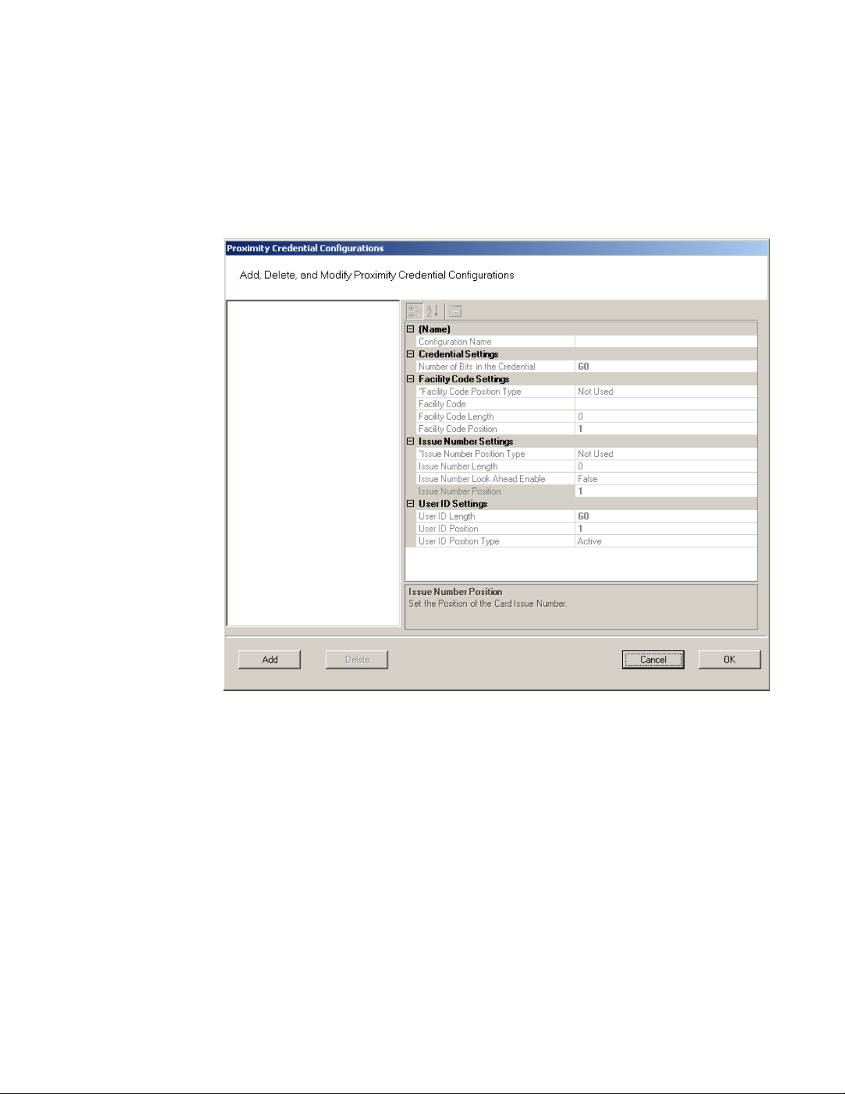
Figure 80 Proximity Credential Configurations
To add a card configuration, perform the following steps.
1 Click Add. Give your new configuration a name in the Configuration Name field.
2 Under Credential Settings, select Number of Bits in the Credential. Change the
number to the right (default 60) to match the number of bits on your card.
3 If your card is configured to include the facility code, change Facility Code
Position type to Active. The facility code fields below will activate.
a Enter your facility code in the Facility Code field.
b Change the Facility Code Length to match the number of bits in your facility
code.
c Change the Facility Code Position to match your card.
Note Issue Number Settings are not configurable for proximity cards. Proceed to User
115

ID Settings.
4 Under the User ID Settings category, change the User ID Length to the number
of bits used for User IDs on your card. Set the User ID Position.
5 When finished, click OK.
Daylight Saving Settings
You can set Wi-Q AMS to automatically respond to Daylight Saving Time settings.
When you select North American as the Daylight Saving Type, the system defaults to standard Daylight Saving Time settings. When you select Europe as the
Daylight Saving Type, the system defaults to the settings for Europe. When you
select Southern Hemisphere, the system defaults to the settings for the Southern
Hemisphere. Once the settings are selected, the system will adjust to Daylight
Saving Time automatically.
To change Daylight Savings Settings, place the cursor in the field next to Daylight
Saving Type and select the type you wish to use. The settings below change to the
defaults for that setting.
I/O
If you are using input/output devices in your system, they are recognized and
defined similar to a Controller.
For example, if you are using a WAC to collect transactions from an alarm, you will
see it in your Segment Tree as a “Reader” when its associated Portal Gateway is
brought online. You can define and modify I/O events for the controller under I/O
References.
Adding and Modifying I/O References
1 In the Segment tab, click the I/O References field, and click the ellipsis button
at the far right. The I/O References Setup dialog box opens.
116
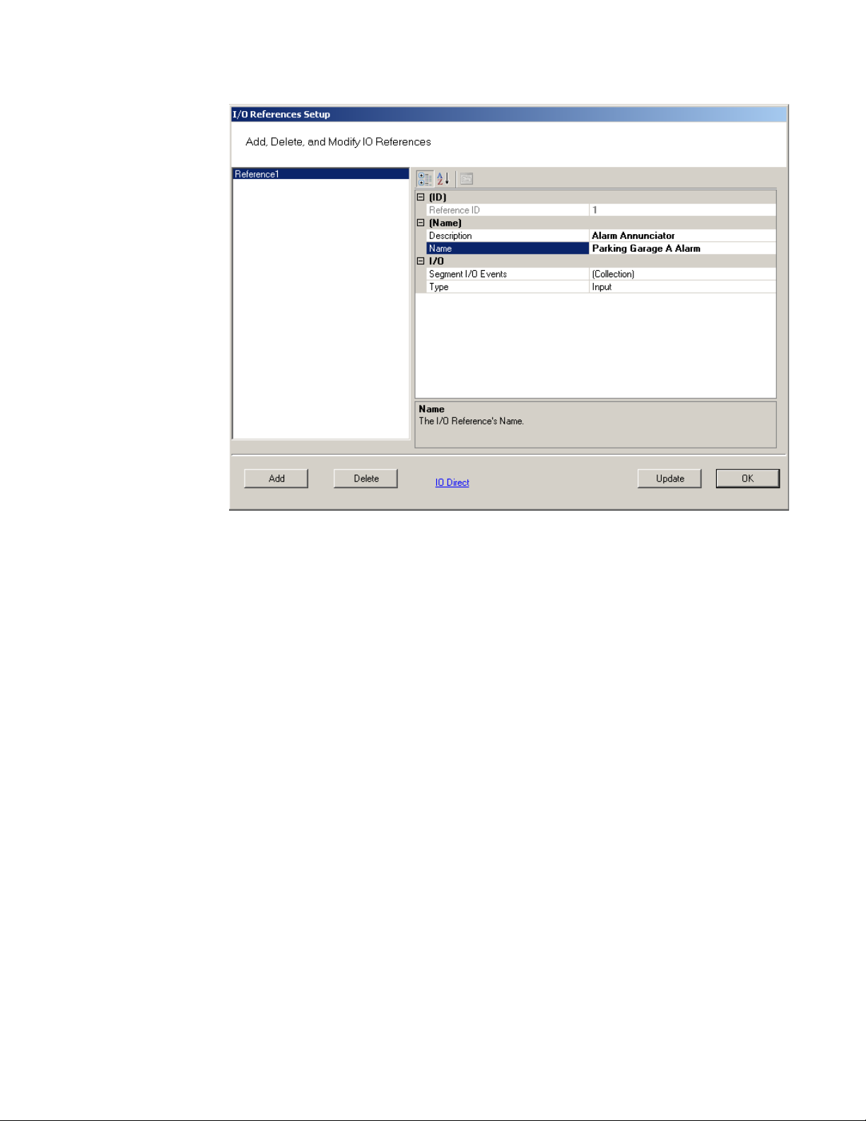
Figure 81 I/O References Setup
Here, you define an event and type for the reference. The system creates an I/O
reference point in the left column of the dialog box and assigns it a reference ID
number.
2 Click Add.
3 Under Description, replace the default description “Reference1’ with a descrip-
tion that will have meaning for your segment, such as Alarm Annunciator.
4 Under Name, replace the default name “Reference1” with a name that will have
meaning for your segment, such as Parking Garage A Alarm.
5 Under the I/O category, click the Segment I/O Events field and select the ellip-
sis button at the far right. This will open the I/O Events Setup window.
117
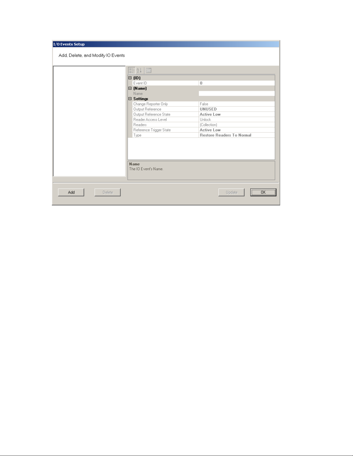
Figure 82 I/O Events Setup
From here you can create an event, check the device’s current state of operation,
define an access level, associate it with a reader in the system, define a trigger
state (high or low), and define the type of event to be triggered.
Note: The system recognizes the WAC as any other “reader” in the system. It will appear
in the referenced dialog boxes as a reader; however, you will recognize it by its
MAC address.
6 Click the Add button. The system creates an Event ID and adds it to the list in
the left hand column.
7 Enter a name for the event, such as Fire Alarm A.
8 Under the Settings Category, click the Readers field and click the ellipsis but-
ton.
9 This will open up a new window. See Figure 83. Select a device from the Read-
ers in Segment section that will be associated with the event.
10 Click Add << to add it to the list of Readers Associated with I/O Event list.
118
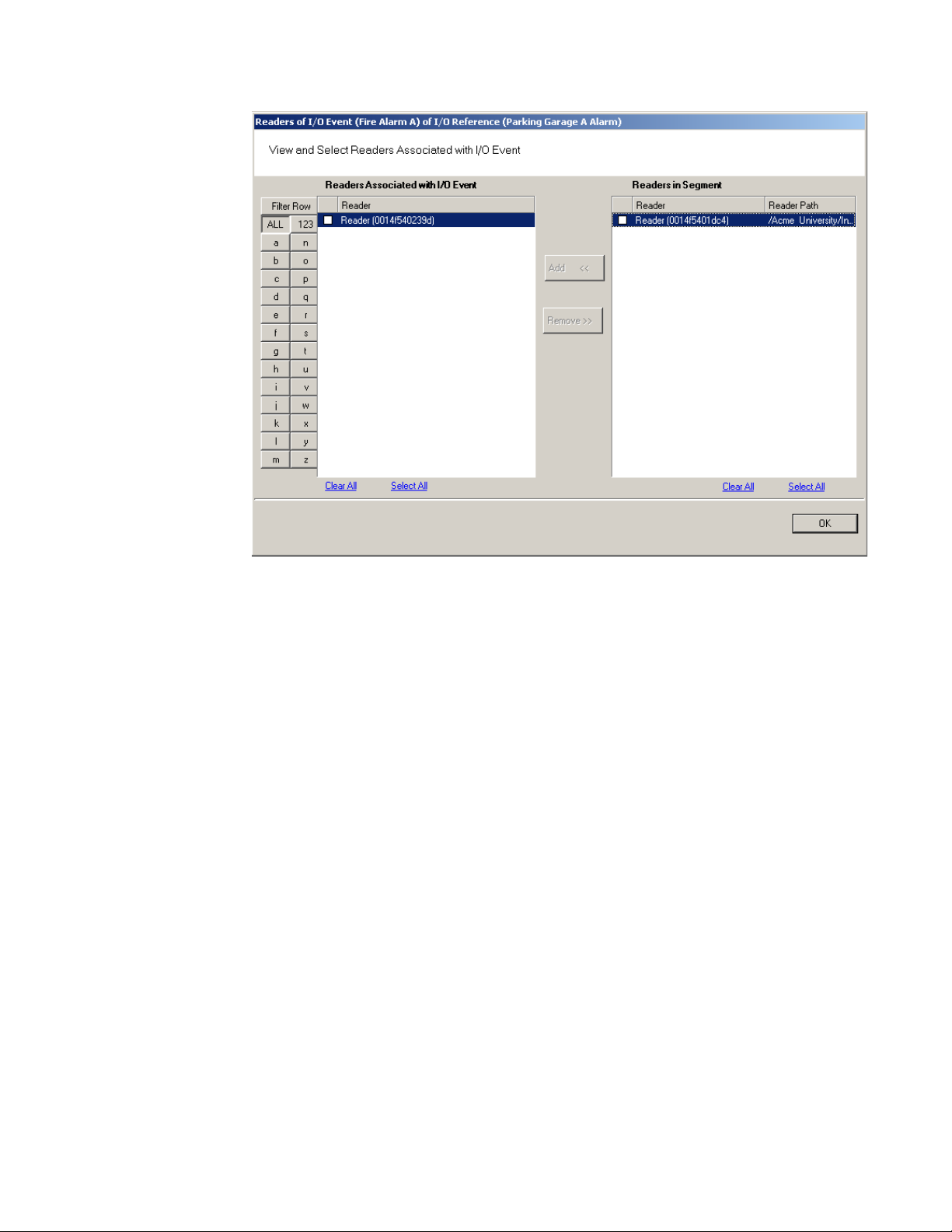
Figure 83 Associating an I/O event with a Reader
11 Click OK to save the association and return to the Setup dialog.
12 In the Reader Access level field, select either Unlock or Lockout from the drop-
down list.
13 In the Reference Trigger State field, select either Active High or Active Low
from the drop-down list (this reference will act as a toggle from one state to
the other).
14 Under Type, select the event type from the drop-down list.
Restore Readers To Normal
Change Output Reference
Override Reader Access Level
Override Timezone User Group Access
Restore Output Reference To Normal.
15 Click Update and continue defining devices then click Finish to save your set-
tings and exit the dialog box.
119
Misc
This category contains three fields (Contact 1, Contact 2, and Reference) that you
can use to store any miscellaneous information you that will be helpful to you and
your system. For example, you may decide to enter the phone number or email address for Stanley Technical Support in case you experience technical difficulties.
PIN Settings
If your system will require user PINs, you may set the PIN length here. Perform
the following steps.
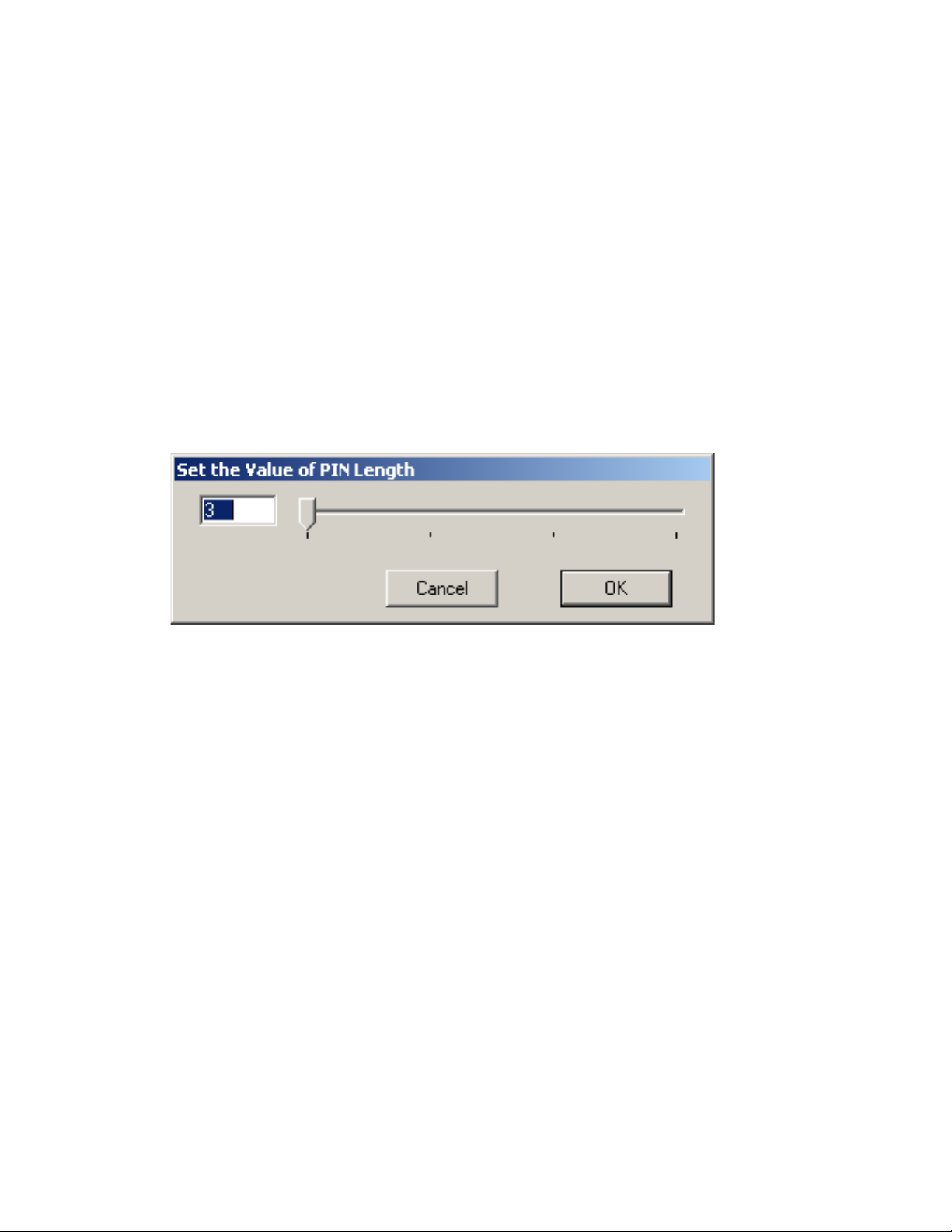
1 Click in the PIN Length field, and select the ellipsis button at the far right. The
PIN Length window opens.
Figure 84 Set the Value of PIN Length
2 Set the value to a number between 3 and 6 by typing it in or sliding the bar to
select the position of the PIN length you will use on segment cards. Then, press
OK.
120
Adding Users to the Segment
The system is now ready for you to add users. Follow the steps in this section the
first time you enter users, and each time you add a new user to the system. To get
started, navigate to the Users tab within the Configurator module.
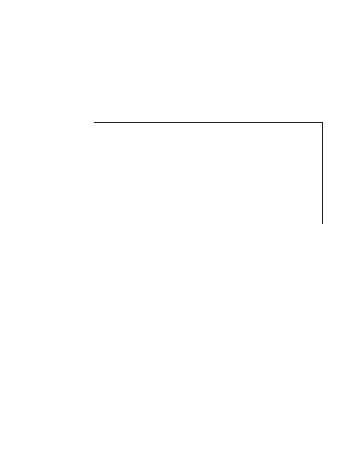
Before You Begin
Before you begin adding users to the system for the first time, be prepared to address the following items:
If... Then...
You plan to use only keypad Controllers AMS assigns a unique keypad credential to each new
You plan to use card readers You must know the card type and settings required for
You plan to use a serial scanning device at your
computer to register user credentials
You plan to use local readers to register credentials
user and automatically registers it with the system.
that t ype.
The scanning device must be attached to the computer com port and you must be able to identify that
port (Com1, Com 2) when you register the credential.
Know the reader name and locations to be used.
You plan to manually enter the credential
numbers
Have a credential number list or creating conventions
ready to enter.
Note If you do not have this information, contact your System Administrator before you
begin.
121
Users Tab Overview
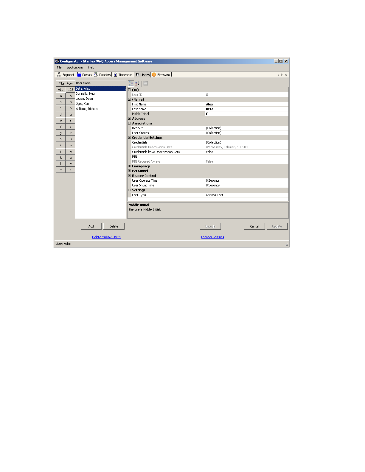
Figure 85 User s Tab
In the Users Tab, all users currently in the system display in the list on the left. If
you have a large number of users, you can use the alphabet buttons on the far left
to quickly sort through the list. Users Categories display on the right. By default,
these categories display as shown; however you can click the A-Z sort button to
display categories alphabetically. Here you can add or remove users from the system, set their credentials, and include any personal information needed to identify
that person in the system.
If an ellipsis button displays when you select a field, additional parameters are
available for selection. From here you will define user name and address information and access parameters such as readers, user groups, credentials, PIN, and so
on.
Note If you see a need for additional fields to define for your Users, contact your System
Administrator. They can add more fields to the Users Tab, or create additional User
Fields unique to your organization.
122
The following sections describe each category in the Users Tab, and present steps
for adding and configuring users in the system.
ID — When you add a user, the system automatically assigns them a unique ID
and displays the number in the User ID field.
Name — Provides entry fields for Users’ first and last name and middle initial.
Adding a User Name
1 In the Users Tab, select the Add User button. In the ID category, the system will
display a new unique User ID.
2 In the First Name line, highlight and replace the default text (example: User1)
with a first name.
3 In the Last Name field, highlight and replace the default text
(“_New”) with a last name. Add a Middle Initial if needed.
Note The Update button will flash to remind you to update your settings. You can update
each time you add a user, or wait until all user information is added. The software
will automatically update your settings when you exit the Users tab.
User Defined Categories and Fields— If your segment has been configured with
user defined categories and fields, such as Address, City, Zip Code, enter the
information as configured.
Associations — In this category, you associate Users with Readers and User
Groups. This task defines which readers will recognize the User’s requests for
entry and exit. If User Groups have been created for your organization, these will
also be available for selection from the Associations category.
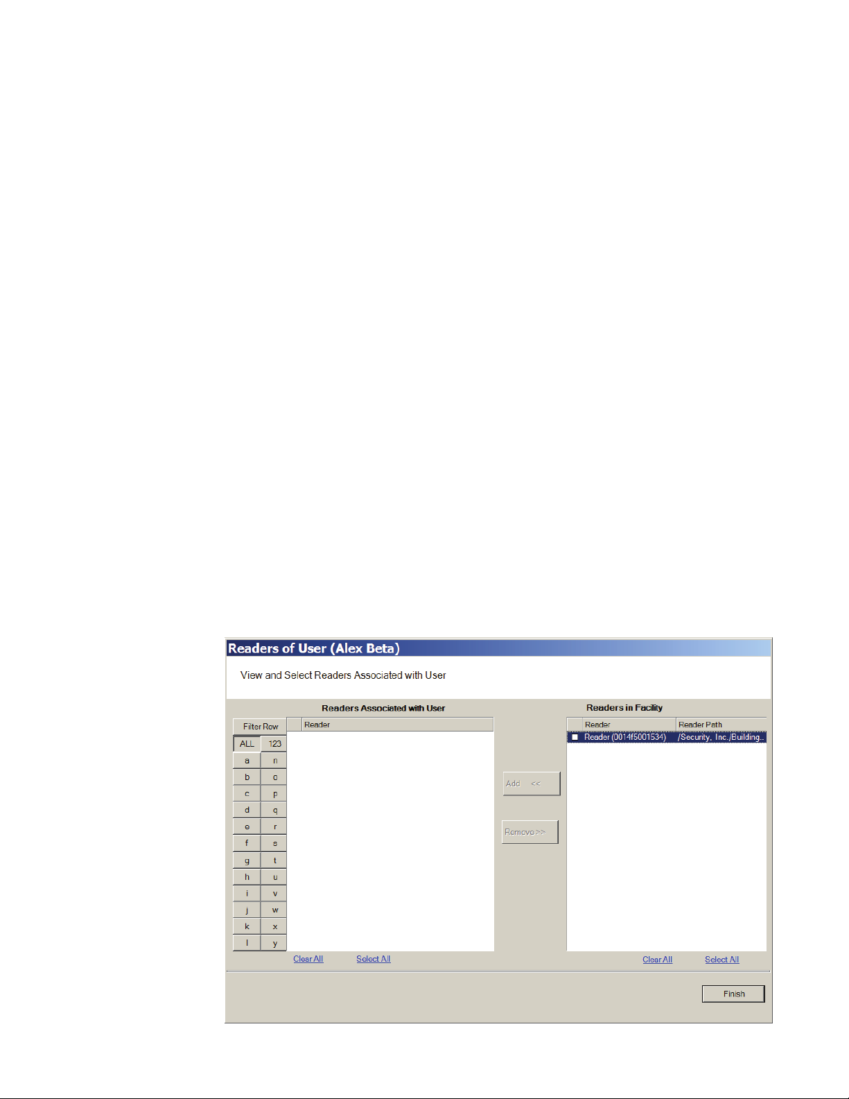
To associate a user with readers
1 In the Associations category, click inside the Readers field, and select the el-
lipsis button at the far right.
2 The Readers of User dialog box opens and displays a list of readers available to
the User.
Figure 86 Readers of User
123
3 Select the reader(s) from Readers in Segment.
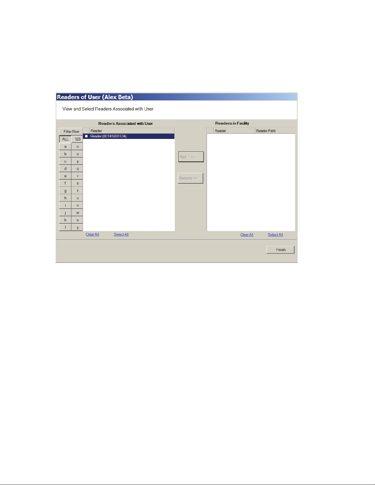
4 Select Add <<. The selected readers are moved from the Readers in Segment
list to the Readers Associated with User list on the left. You can associate a
user with any number of readers.
Figure 87 Selecting a reader to associate with a user
5 Select OK to save your settings and return to the Users Tab.
User Groups
If User Groups have been created for your segment, these will already be associated with readers. For example, a User Group may have been defined for
Laboratory Building 1. Laboratory Building1 might have six readers. By assigning
the User to the Laboratory Building 1 Users Group, they will automatically be associated with all the readers in that group.
A User Group may also be defined as a Timezone Group. Timezone User Groups
further define access levels for the Master Timezone. You can restrict access of
certain groups of employees to a specific time period. For example, you may have
a housekeeping group designated as a Timezone Group with restricted access
to dormitories from 8:00 a.m. to 4:00 p.m., weekdays only. You would then assign
Users from the housekeeping department to this group. Steps to add users to User
Groups are presented in the following section. For more information about creating Timezone Groups, see “Timezone User Group Collections” on page 142.
124
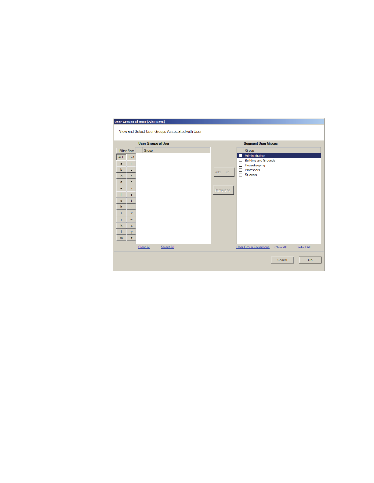
Perform the following steps to add a user to a User Group.
To add a user to a User Group
1 When adding or editing a User, in the Associations Category, click in the User
Groups field and click the ellipsis button. The User Groups of User dialog box
opens.
Figure 88 User Groups of User
2 Select the group(s) to associate with this user and click the Add << button. The
groups are added to the User of Groups list.
3 Select OK to save your selections and return to the Users Tab. You can add or
change User Groups for a user any time by returning to this list.
Credential Settings
Wi-Q AMS tracks individual requests for access or exit from the segment by their
unique credentials, and each request is recorded as a transaction in the database
for reference. Whether your organization uses keypad Controllers or card readers,
each user will be assigned a unique credential number. Under Credential Settings, you will enter the credential ID and number, select a credential type, and set
additional parameters related to the credential type. You can add another level of
security by combining an individual’s credential with a personal ID number (PIN).
If your organization requires a PIN, you will enter them here. Credential setup is
a two-step process: First you will select the credential type to be used, then you
125

will register the credential.
Keypad Type — The default credential type in AMS is Keypad. When you add a
user to the system, the software assigns them a unique keypad credential number, then automatically registers it with the system. If your segment uses only
keypads, once you add the new user name, you can skip to Adding PINs and
Expirations Dates.
Card Type — If your segment uses card type credentials, you must select the card
type, enter the appropriate settings, and then register the credential number with
the system.
To select the card type
1 In the Users Tab, Credentials line, select the ellipsis button. The User Creden-
tials Setup dialog box opens. The credential types are listed on the left and the
categories available for each type are listed on the right.
Figure 89 Selecting a User Credential type
126
2 Select the type of credential the reader will use, for example, Keypad. The
credential options in the categories on the right will change, depending on the
type selected.
Passage Mode Authority — User credential has the authority to activate passage
mode with 2 entries.
1st Card Unlock Authority — User credential has the authority to leave the door
unlocked when in an ‘unlock with ID’ access mode.
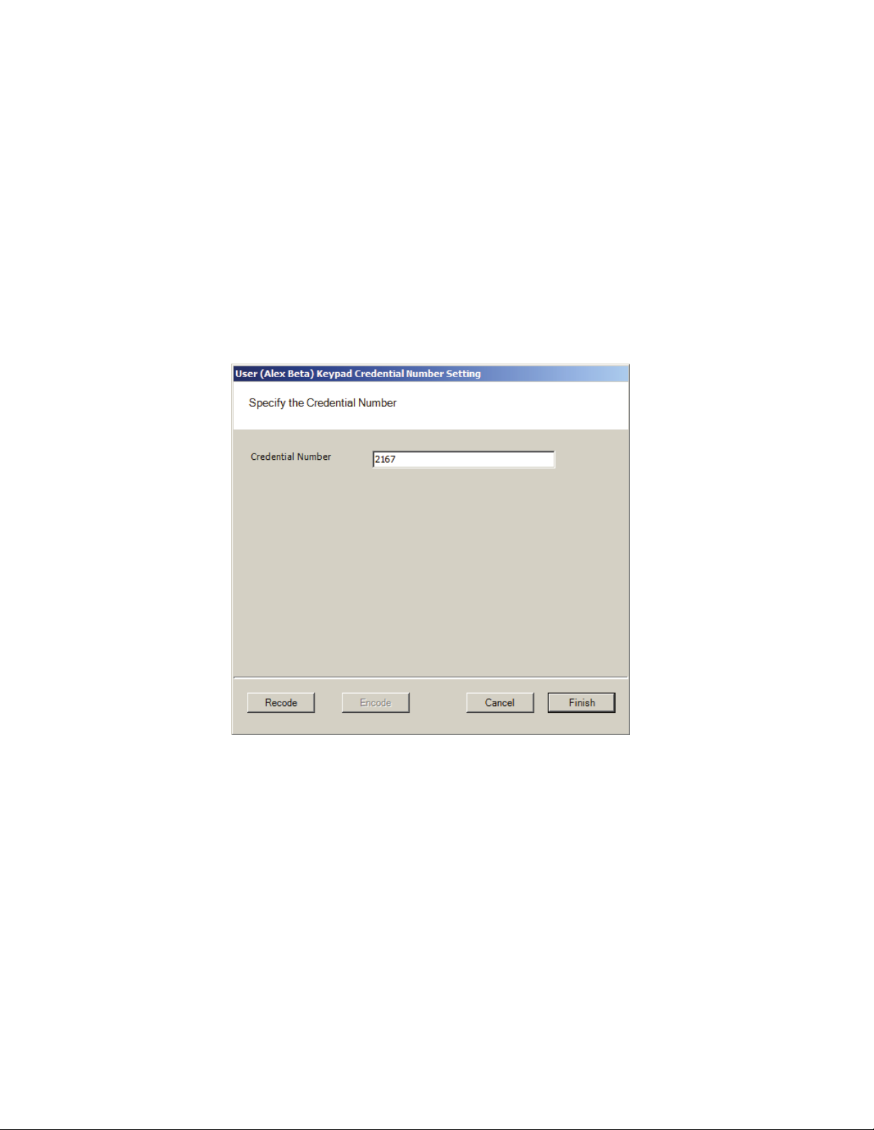
3 Under the credential category, click the Number field and click the ellipsis but-
ton. The Specify the Credential Number dialog box opens.
Figure 90 Enter a user credential number
4 If you wish to have the software generate a new number, select Recode. Or,
you may type in the user’s credential number. Click Finish. You can change the
credential number at a later date if needed.
5 Now you are ready to register the credential.
Note If the credential type you need is not in the list of card types on the left, you can
add one. See “Adding a Credential Type” on page 131.
Credentials Deactivation Date — You can define whether a user’s credentials
can be automatically de-activated based on an expiration date. This is useful, for
example, when entering credentials for a temporary employee or contractor. If the
credential can expire, select True from the drop-down list next to the Credentials
have Deactivation Date field, and then enter the de-activation date in the Creden-
127
tials Deactivation Date field. If the credential cannot be de-activated, select False
from the drop-down list. The default deactivation date is 26 years to ensure a
user’s credential is not inadvertently deactivated.
Registering the Credential
When you click on the Number field below the Credential category and select the
ellipsis button, the Specify the Credential Number dialog box opens. From here,
you can enter the credential number manually, scan the user’s card with a scanning device connected to your computer, or specify a reader where the user will
scan their card. Steps to register each type of card are presented in the next few
sections.
Note If you use the reader scan method, the card used must be unassigned.
To register a Keypad credential
1 Keypad credentials are automatically registered by the system, and no further
steps are required.
To register a Magnetic Stripe Card credential
1 From the User Credential Setup dialog box, select Mag Card from the list.
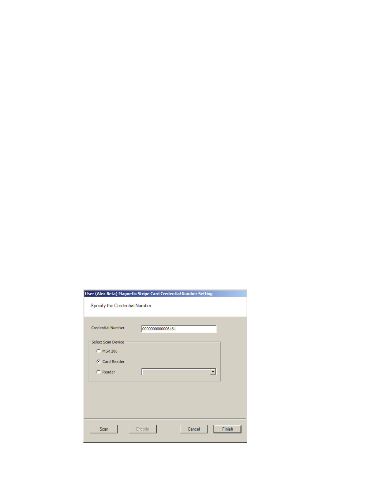
2 Click in the Number field and select the ellipsis button. The Users Magnetic
Stripe Card Credential Number Setting dialog box opens.
Figure 91 Entering a Magnetic Card credential number
128
3 Enter a Credential Number manually (must be less than 16 characters, zeros
will be appended) or select a scan device.
Using a scanning device to register a credential
You can use a scanning device connected to your computer to register a credential.
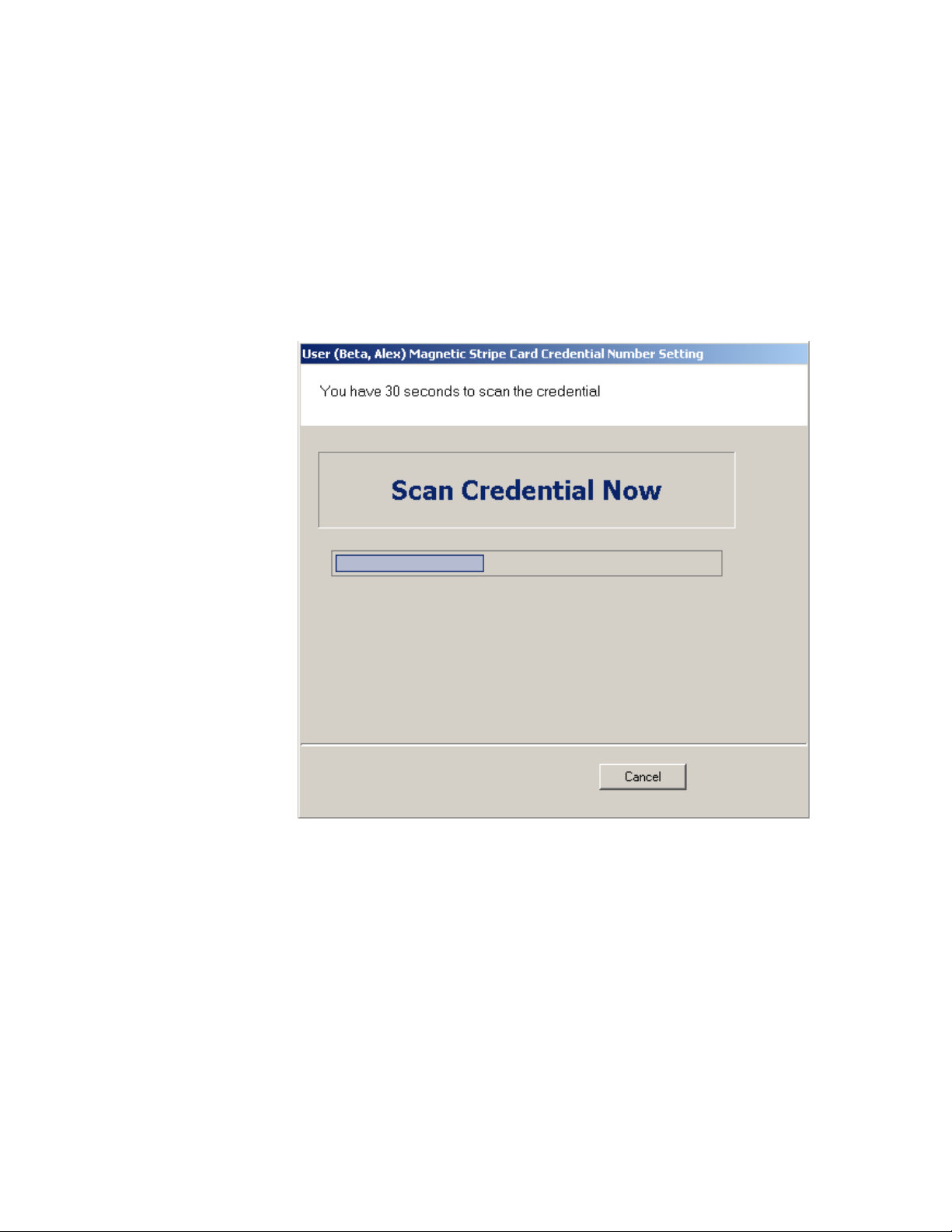
1 Select Card Reader. When you are ready to scan the card, select the Scan but-
ton. You will have 30 seconds to scan the card.
Figure 92 Scan Credentials
2 When recognized, the number will display in the Credential Number text box.
3 Select Finish and return to the Credential Setup dialog box.
Using a local reader
You can use a local reader to scan the card credentials.
1 Select Reader, and then use the drop-down list to navigate to the reader where
the card will be scanned. When you are ready to scan the card, select the Scan
button. You will have 30 seconds to scan the card. When recognized, the number will display in the Credential Number text box.
2 Select Finish and return to the Credential Setup dialog box.
129
Note You may need to expand the drop-down list to view all available readers. Use the
highlighted area in the lower right corner.
Registering a Prox card credential
In the Proximity Card category, review the Prox Card Type. If the default entry
is not the one you will use, select the field and use the down-arrow to select the
correct type from the list.
To register a Prox Card Credential
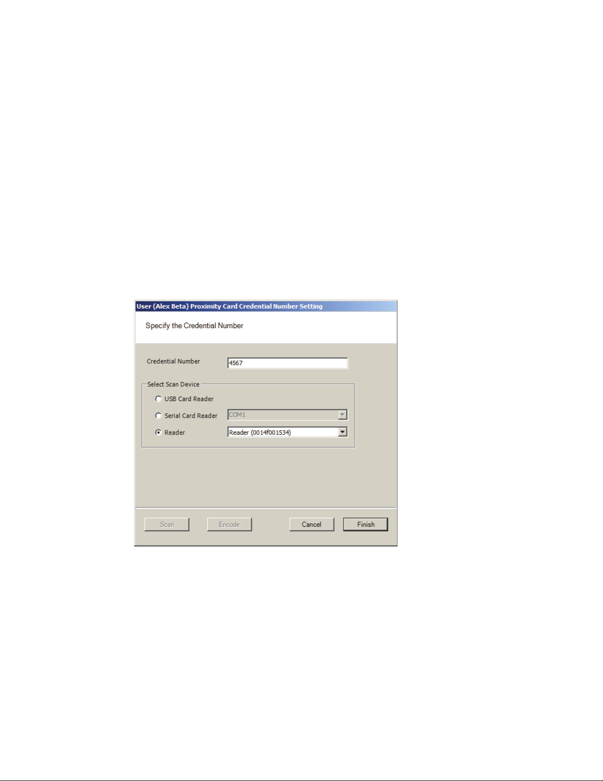
1 Select Prox Card from the list on the left. Click the ellipsis in the Number field,
under the Credential category. The User Proximity Card Credential Number
Setting dialog box opens
Figure 93 Entering a Proximity Card credential number
130
2 Enter a Credential Number manually (must be less than 16 characters, zeros
will be appended) or select a scan device:
USB Card Reader
If you have a MSR 206 USB Card reader connected to your computer, select MSR
206.
1 When you are ready to scan the card, select the Scan button. You will have
30 seconds to scan the card. When recognized, the number will display in the
Credential Number text box.
 Loading...