


D.O.R.C. International b.v.
SERVICE
MANUAL
6700
Associate Dual Unit
Manufacturer : |
Distributor in the USA: |
||
Dutch Ophthalmic Research Center |
Dutch Ophthalmic USA |
||
International b.v. |
10 Continental Drive, Bldg 1 |
||
Scheijdelveweg 2 |
Exeter, NH 03833 |
||
3214 VN Zuidland |
U.S.A. |
|
|
The Netherlands |
Phone |
: 800-75-DUTCH or 603-778-6929 |
|
|
|
||
Phone |
: +31 181 458080 |
Fax. |
: 603-778-0911 |
Fax. |
: +31 181 458090 |
: sales@dutchophthalmicusa.com |
|
: sales@dorc.nl |
|
|
|
Website |
: www.dorc.nl |
|
30203300-G |
|
|
|
|
TECHNOLOGY CREATED BY VISION

D.O.R.C. International b.v. |
|
|
Contents |
|
|
Section 0 – Revision Information.................................................................................................................................... |
3 |
|
Section 1 - General Information ...................................................................................................................................... |
4 |
|
1.1 |
Introduction ......................................................................................................................................................... |
4 |
1.2 |
Description of this manual .................................................................................................................................. |
5 |
1.3 |
Warranty.............................................................................................................................................................. |
5 |
1.4 |
Description of the unit......................................................................................................................................... |
5 |
1.7 |
Description of the remote control........................................................................................................................ |
7 |
1.8 |
Audible tones ...................................................................................................................................................... |
7 |
1.9 |
Specifications ...................................................................................................................................................... |
8 |
Section 2 - Theory of Operation..................................................................................................................................... |
10 |
|
2.1 |
Block schedule .................................................................................................................................................. |
10 |
2.2 |
User Interface .................................................................................................................................................... |
12 |
2.3 |
Description of Phaco ......................................................................................................................................... |
12 |
2.4 |
Description of Vitrectomy................................................................................................................................. |
12 |
2.5 |
Description of Irrigation/Aspiration .................................................................................................................. |
13 |
2.6 |
Description of Diathermy.................................................................................................................................. |
13 |
2.7 |
Description of Triple Port Illumination ............................................................................................................. |
13 |
2.8 |
Description of Air module................................................................................................................................. |
13 |
2.9 |
Description of Viscous Fluid Injection module................................................................................................. |
13 |
2.10 Description of Viscous Fluid Extraction Module............................................................................................ |
14 |
|
Section 3 - Maintenance Instructions ............................................................................................................................ |
15 |
|
3.1 |
General Information .......................................................................................................................................... |
15 |
3.2 |
Warnings ........................................................................................................................................................... |
16 |
3.3 |
Recommended Spare Parts ................................................................................................................................ |
17 |
3.4 |
Periodical Instructions for Preventive Inspection and Maintenance.................................................................. |
17 |
3.5 |
Returning the Unit for Repairs .......................................................................................................................... |
17 |
3.6 |
User or Operator Instructions for cleaning the ASSOCIATE®.......................................................................... |
17 |
3.7 |
Replacing the Fuses........................................................................................................................................... |
18 |
3.9 |
Disassembly of the Top Cover .......................................................................................................................... |
20 |
3.10 Replacing the Harddisk ................................................................................................................................... |
20 |
|
3.11 Remove the LCD screen.................................................................................................................................. |
21 |
|
Section 4 – Schematics.................................................................................................................................................... |
23 |
|
4.0 |
Block schedule Mainpower ............................................................................................................................... |
23 |
4.1 |
Block schedule Userinterface............................................................................................................................ |
24 |
4.2 |
Block schedule PCB Electronic functions......................................................................................................... |
26 |
4.3 |
Block schedule pneumatic................................................................................................................................. |
27 |
4.3.1 Block schedule pneumatic 1500 cuts.............................................................................................................. |
27 |
|
4.3.2 Block schedule pneumatic 2500 cuts.............................................................................................................. |
28 |
|
4.4 |
Mainpower ........................................................................................................................................................ |
29 |
4.5 |
Overview Power supply .................................................................................................................................... |
30 |
Powersupply Embeddedboard and Instruments (20615100) Rev:1......................................................................... |
31 |
|
4.6 |
Powersupply PC (206146) Rev:3 ...................................................................................................................... |
34 |
4.7 |
baseplate embeddedboard (206151 Rev:3)....................................................................................................... |
37 |
4.8 LED-FRAME front ........................................................................................................................................... |
44 |
|
4.10 Remote controlle receiver................................................................................................................................ |
48 |
|
4.11 Remote control transmitter .............................................................................................................................. |
49 |
|
4.12 Embeddedboard............................................................................................................................................... |
50 |
|
4.13 Light ................................................................................................................................................................ |
58 |
|
4.14 Phaco and Diathermy ...................................................................................................................................... |
60 |
|
Service Manual |
Page 2/63 |
30203300-G |

D.O.R.C. International b.v.
Section 5 - Update letter ................................................................................................................................................ |
61 |
|
5.1 calibration and test software.............................................................................................................................. |
61 |
|
5.2 |
Introducing 2500 cutting range from SN200451214 to SN20051243 .............................................................. |
62 |
5.3 |
Introducing 2500 cutting range from SN 200451243 ...................................................................................... |
62 |
5.4 |
Introducing new GUI from SN 200651421 ...................................................................................................... |
63 |
5.5 |
Introducing Embedded XP from SN 200751421............................................................................................... |
63 |
Section 6 - Warranty...................................................................................................................................................... |
63 |
|
Section 0 – Revision Information
Datum |
Revision |
Description |
From serial number |
2002 |
A (Version 1.0) |
First version |
|
2003 |
B (Version 1.1) |
New power supply pcb 206152 Rev:01 |
200351179 |
|
|
Modification base plate. 206151 Rev:03 |
|
2004 |
C (Version 1.2) |
Text update |
|
2004-08 |
D (Version 1.3) |
To prepare 2500 cuts range |
200451214 |
|
|
Introducing 2500 cuts range |
200451243 |
2005-01 |
E (Version 1.4) |
Text update specification page |
|
2007-03 |
F (Version 1.5) |
Introduction new PC-board with XP |
200751421 |
|
|
Embedded and introduction GUI 2.5 |
|
2008-03 |
G |
Upgrade front page |
|
Service Manual |
Page 3/63 |
30203300-G |

D.O.R.C. International b.v.
Section 1 - General Information
1.1 Introduction
The ASSOCIATE® provides all necessary functions to perform phaco and vitrectomy surgery. The unit includes eight separate function modules, a remote control and a footswitch.
The function modules are:
·Phaco-Emulsification / Fragmentation Module
·Vitrectomy Module
·Irrigation/Aspiration Module
·Diathermy Module
·Triple Port Illumination Module
·Air Module
·VFI Module
·VFE Module
These modules may be used together, or in combination. Functions of some of the modules are interactive. For example, when the Phaco & Vitrectomy Module is activated, the Irrigation/Aspiration Module is activated also. A Footswitch provides a convenient way of controlling several modules at once.
The phaco and vitrectomy modules are prepared for a future combination with a laser source.
To provide the ophthalmic surgeon the optimum convenience, the ASSOCIATE® is equipped with a dual pump system, Peristaltic and Venturi selectable for both anterior and posterior surgery.
High Vacuum Sensor Cartridge
The ASSOCIATE® operates on one cartridge suitable for Peristaltic and Venturi aspiration system and is suitable for both anterior and posterior segment surgery. An integrated microprocessor guarantees an optimal intraocular vacuum and High Vacuum Occlusion Technology for advanced capsular protection in phaco surgery. Due tot the integrated microprocessor technology, a maximum sterile barrier is guaranteed.
The first part of this manual includes some general instructions for the unit. This is followed by specific descriptions of each of the modules, in the order listed above. The end of the manual includes a list of the accessories which may be used with the unit.
The ASSOCIATE® complies with the safety standards as described in the international norm: IEC 60601-1 class 1 type BF. The unit complies with IEC-60601-1-2.
Service Manual |
Page 4/63 |
30203300-G |
D.O.R.C. International b.v.
1.2 Description of this manual
The purpose of this manual is to provide the field engineer with the necessary information to maintain and repair the ASSOCIATE®.
1.3 Warranty
D.O.R.C. International b.v. warrants that all possible care was used in the choice of materials and manufacture of its products.
D.O.R.C. International b.v. shall not be liable for any incidental or consequential loss, damage or expense, arising from abuse of its products. However, if D.O.R.C. International b.v.'s investigation shows that its products were defective at the time of shipment by D.O.R.C. International b.v., products will be replaced/repaired at no charge.
Otherwise all D.O.R.C. International b.v. equipment is covered with a full year warranty, which does not cover the accessories.
D.O.R.C. International b.v. neither assumes backflush authorizes any other person to assume for it, any other or additional liability or responsibility in connection with its products.
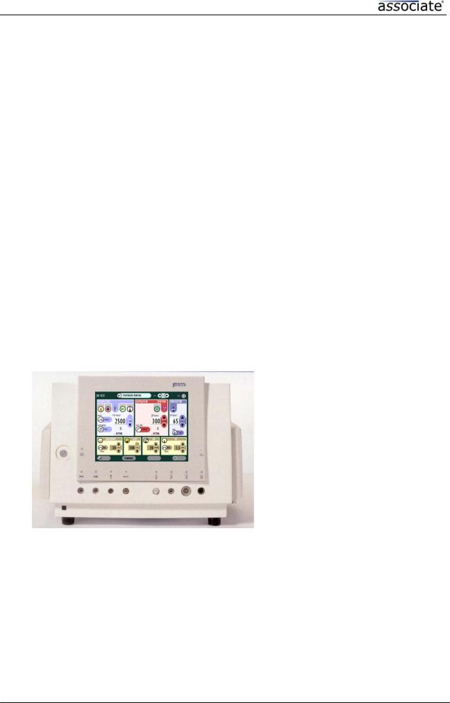
1.4 Description of the unit
|
|
|
|
|
|
10 |
|
|
|
||||||
|
|
|
|
|
|
|
|
|
|
|
|
|
1) |
Triple-port light connector |
|
|
|
|
|
|
|
|
|
|
|
|
|
|
|
||
|
|
|
|
|
|
|
|
|
|
|
|
|
|
||
|
|
|
|
|
|
|
|
|
|
|
|
|
2) |
Scissors connector |
|
|
|
|
|
|
|
|
|
|
|
|
|
|
3) |
Proportional scissors connector |
|
|
|
|
|
|
|
|
|
|
|
|
|
|
4) |
VFI connector |
|
|
|
|
|
|
|
|
|
|
|
|
|
|
5) |
Air connector |
|
|
|
|
|
|
|
|
|
|
|
|
|
|
|
6) |
Pneumatic vitrectome connector |
|
|
|
|
|
|
|
|
|
|
|
|
|
|
||
1 |
|
|
|
|
|
|
|
|
|
|
|
|
|
7) |
Electric vitrectome connector |
|
|
|
|
|
|
|
|
|
|
|
|
|
8) |
Phaco connector |
|
|
|
|
|
|
|
|
|
|
|
|
|
|
|||
|
|
|
|
|
|
|
|
|
|
|
|
|
|
||
|
|
|
|
|
|
|
|
|
|
|
|
|
|
9) |
Diathermy connector |
|
|
|
|
|
|
|
|
|
|
|
|
|
|
10) ON/OFF indicator |
|
|
|
|
|
|
|
|
|
|
|
|
|
|
|
|
|
|
|
|
|
|
|
|
|
|
|
|
|
|
|
|
|
|
|
|
|
|
|
|
|
|
|
|
|
|
|
|
|
2 |
3 |
4 |
5 |
6 |
7 |
8 |
9 |
Fig.2
D.O.R.C. Associate® - Front View
Service Manual |
Page 5/63 |
30203300-G |

D.O.R.C. International b.v.
1) Inlet pressure connector
2) Brightness control User Interface
3) VFI+ (to set-up VFI syringe)
4) Infusion pole connector
5) Footswitch connector
6) Auxiliary/Vitrectomy interface
1 connector
7) Earth potential point
8) ON/OFF switch
2 |
3 |
4 |
5 |
6 |
7 |
8 |
|
|
|
|
|
|
Fig. 3 |
D.O.R.C. ASSOCIATE® - Rear View
Fig.4
D.O.R.C. ASSOCIATE® - Side View
Handle to release cartridge
Fig. 5
D.O.R.C. ASSOCIATE® - Side View (without cartridge set in place)
Service Manual |
Page 6/63 |
30203300-G |
D.O.R.C. International b.v.
1.5 Description of the footswitch
The unit includes a multi function Footswitch which allows the surgeon to control many different functions on the ASSOCIATE®. For more detailed explanations, see the instruction manual.
Fig. 5
Ergo Footswitch
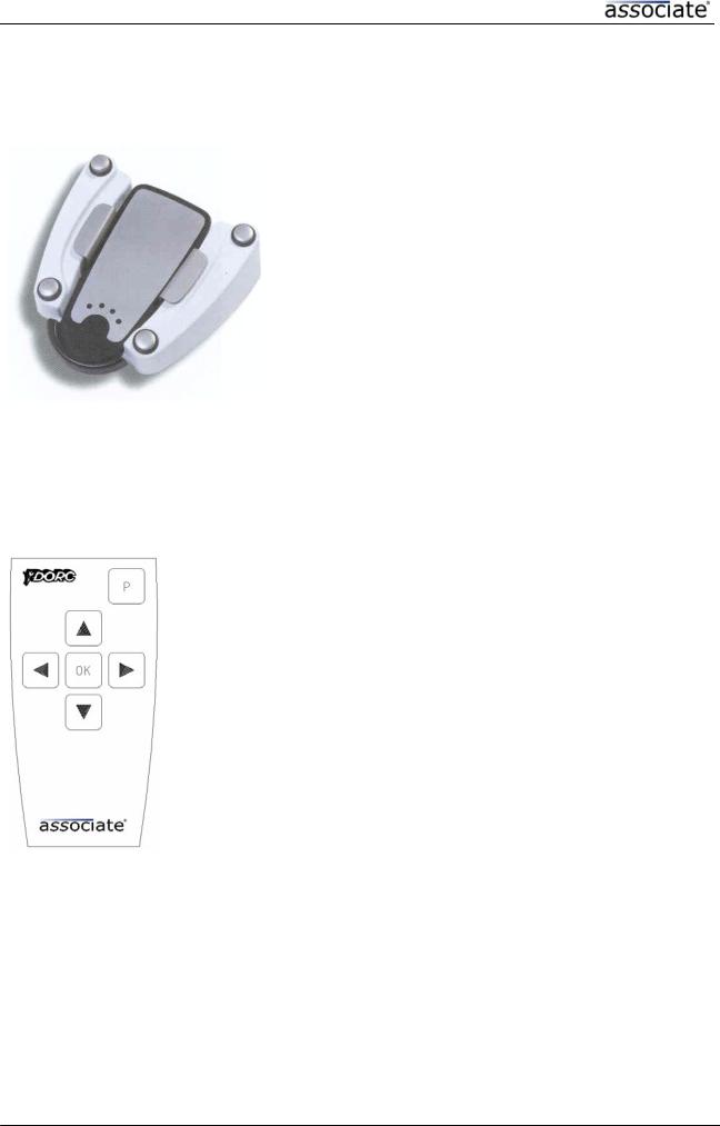
1.7 Description of the remote control
The ASSOCIATE® is standard supplied with an infra-red remote control to select and control all surgical functions without touching the user’s interface screen.
The ASSOCIATE® Remote Control can be placed in a sterile bag to be used in the sterile field for surgeon and/or operating staff.
By depressing the UP/DOWN, LEFT/RIGHT button cursor lights up and is skipping to the next function mode.
Select the requested function mode with the cursor and by depressing the “O.K.” button, the selected function will be activated or preset UP/DOWN.
NOTE : the remote control is only functional in the main menu, priming and surgical screens.
Fig. 6
Remote Control
1.8 Audible tones
The ASSOCIATE® can generate audible tones in several different patterns, depending on the functions in use at the time. The volume can be controlled using the system setting screen.
Service Manual |
Page 7/63 |
30203300-G |

D.O.R.C. International b.v.
1.9 Specifications
GENERAL |
|
|
|
Apparatus |
|
: |
ASSOCIATE® |
Type : |
|
|
|
Compact Version |
|
: |
6600 |
Dual Version |
|
: |
6700 |
Weight |
|
: |
35 Kg. |
Dimensions : |
|
|
|
Console |
|
: |
50 x 50 x 36 cm. |
Display |
|
: |
10.1 inch |
INPUT |
|
|
|
Mains supply |
|
: |
100VAC~/120VAC~50/60Hz |
|
|
|
230VAC~/240VAC~50/60Hz |
Fuses |
|
: |
2 x at 100VAC~-120VAC~AT T6,3A |
|
|
|
2 x at 230VAC~-240VAC~AT T3,15A |
Power consumption |
|
: |
600VA (max. ASSOCIATE® Configuration) |
Air pressure input |
|
: |
5-6 BAR / 35-40 lt. Flow (consumption) |
(medical grade filtered air !) |
|
|
|
Pump |
|
: |
Peristaltic or Venturi |
I/A MODULE Preset : |
|
|
|
Vacuum linear |
: |
|
from 0-500 mmHg |
|
|
|
In case of Peristaltic Pump : also 1-50 cc/min. |
VITRECTOMY MODULE : |
|
|
|
Pneumatic Cutting range |
: |
100-2500 cuts/minute linear (+/- 10%) |
|
Electric Cutting range |
|
: |
100-1500 cuts/minute linear |
SCISSORS MODE : |
|
|
|
Scissors Cutting Range |
: |
60-600 cuts/minute |
|
Proportional Scissors Mode |
: |
0-100% linear open/close action |
|
PHACO EMULSIFICATION/ |
|
|
|
FRAGMENTATION MODULE : |
|
|
|
Power Consumption |
|
: |
50 Watts |
Frequency |
|
: |
40 kHz |
Autotuning |
|
|
|
(The ASSOCIATE® is prepared for a future combination with an Auxiliary Unit)
TRIPLE PORT ILLUMINATION MODULE : |
|
||
Lamp |
: |
24V / 150 Watts Halogen bulb, including |
|
|
|
automatic back-up bulb |
|
|
|
|
|
Service Manual |
|
Page 8/63 |
30203300-G |

D.O.R.C. International b.v.
DIATHERMY MODULE : |
|
|
Output |
: |
(values at room temperature) |
RF Output |
: |
0-7.5 Watts, 100 Ω (1 MHz) loaded, |
|
|
linear and fixed output |
Frequency |
: |
1 MHz, crystal controlled |
AIR MODULE : |
|
|
Air Pressure |
: |
from 0-120 mmHg. |
VFI MODULE : |
|
|
Pressure |
: |
from 0.5-5.0 BAR, linear or fixed pressure |
VFE MODULE : |
|
|
Pressure |
: |
from 10-500 mmHg |
|
|
in case of Peristaltic pump 10-600 mmHg, also 1-50 |
ENVIRONMENT : |
|
cc/min. aspiration flow |
|
|
|
Operation : |
|
|
a)An ambient temperature range of +10°C to +40°C.
b)A relative humidity range of 10% to 85% without condensation.
c)An atmospheric pressure range of 700 hPa to 1060 hPa.
Transport & Storage Conditions :
a)An ambient temperature range of -40°C to 70°C.
b)A relative humidity range of 10% to 95% without condensation.
c)An atmospheric pressure range of 500 hPa to 1060 hPa.
The D.O.R.C. ASSOCIATE® complies with the safety standards as described in the international standard : IEC 60601-1 class 1 type BF & IEC 60601-2-2.
Service Manual |
Page 9/63 |
30203300-G |

D.O.R.C. International b.v.
Section 2 - Theory of Operation
2.1 Block schedule
Air |
|
|
|
|
|
|
|
Vitrectomy |
|
|
|
|
|
|
|
|
|
||
|
|
|
|
|
|
||||
|
5 - 6 Bar |
|
|
Pneumatic |
|
||||
|
|
|
|
||||||
|
|
|
|||||||
|
|
|
|
|
|
|
|
|
|
|
|
|
|
|
|
|
|
|
|
|
|
|
|
|
|
|
|
VFI |
|
|
|
|
|
|
|
|
|
|
|
|
|
|
|
|
|
|
|
|
|
|
|
|
|
|
|
|
|
|
|
|
|
|
|
|
|
|
|
|
|
|
|
|
|
|
|
|
|
|
|
|
|
|
|
|
|
|
|
|
|
|
|
|
|
|
|
|
|
|
|
|
|
|
|
|
|
|
|
|
|
|
|
|
|
|
|
|
|
|
|
|
|
AIR |
|
|
|
|
|
|
|
|
|
|
|
|
|
|
|
|
|
|
|
|
|
|
|
|
|
|
|
|
|
|
|
|
|
|
|
|
|
|
|
|
|
|
|
|
|
|
|
|
|
|
||
|
|
|
|
|
|
|
|
|
|
|
|
|
|
|
|
|
|
|
|
|
|
|
|
|
|
|
|
|
|
|
|
|
|
|
|
|
|
|
|
|
|
|
|
|
|
|
|
|
|
|
|
|
|
|
Aspiration Vacuum |
|
|
|
|
|
|
|
|
|
|
|
|
|
|
|
||||
|
|
|
|
|
|
|
|
|
|
Irrigation & |
|
|
|
|
|
|
|
|
||||||
|
Extern |
Peristaltic / ventury |
|
|
|
|
|
|
|
|
|
|
|
|
|
|
||||||||
|
|
|
|
|
|
Backflush & |
|
|
|
|
|
|
|
|
||||||||||
|
|
|
|
|
|
|
|
|
|
|
|
|
|
|
|
|
|
|
|
|
|
|
|
|
|
infusion pole |
|
|
|
|
|
|
|
|
|
|
|
|
Aspiration |
|
|
|
|
|
|
|
|
||
|
|
|
|
|
|
|
|
|
|
|
|
|
|
|
|
|
|
|
|
|
|
|||
|
|
|
|
|
|
|
|
|
|
|
|
|
|
|
|
|
|
|
|
|
|
|
|
|
|
|
|
|
|
|
|
|
|
|
|
|
|
|
|
|
|
|
|
|
|
|
|
|
|
|
|
|
|
|
|
|
|
|
|
|
|
|
|
|
|
|
|
|
|
|
|
Proportional |
|
|
|
|
|
|
|
|
Dedicated Purpose |
|
|
|
|
|
|
|
|
|
|
||||||||
|
|
|
|
|
|
|
|
|
|
|
|
|
|
Scissors |
|
|
||||||||
|
Extern |
|
Processor |
|
|
|
|
|
|
|
|
|
|
|
||||||||||
|
|
|
|
|
|
|
|
|
|
|
|
|
||||||||||||
|
|
|
|
|
|
|
|
|
|
|
|
|
|
|
|
|
|
|
||||||
|
|
|
|
|
|
|
|
|
|
|
|
|
|
|
|
|
|
|
||||||
|
|
|
|
|
|
|
|
|
|
|
|
Floating |
|
|
|
|
|
|
||||||
|
|
|
|
|
|
|
|
|
|
Rs-232 |
|
|
|
|||||||||||
|
Footswitch |
|
|
|
|
|
|
|
|
|
|
|
|
|
|
|
|
Diathermy |
|
|
||||
|
|
|
|
|
|
|
|
|
|
|
|
|
|
|
|
|
|
|
||||||
|
|
|
|
|
|
|
|
|
|
|
|
|
|
|
|
|
|
|
|
|
||||
|
|
|
|
|
|
|
|
|
|
|
|
|
|
|
|
|
|
|
|
|
||||
|
|
|
|
|
|
|
|
|
|
|
|
|
|
|
|
|
|
|
Phaco |
|
|
|||
|
|
|
|
|
|
|
|
|
|
|
|
|
|
|
|
|
|
|
|
|
||||
|
|
|
|
|
|
|
|
|
|
|
|
|
|
|
|
|
|
|
|
|
|
|
|
|
|
|
|
|
|
|
|
|
|
24Vdc |
|
|
|
|
|
|
|
|
|
|
|
||||
|
|
|
|
|
|
|
|
|
|
|
|
|
|
|
|
|
|
|
|
|||||
|
|
|
|
|
|
|
|
|
|
|
|
|
|
|
|
|
|
|
|
|
|
|||
|
|
|
|
|
|
Power-supply for |
|
|
24Vdc |
|
|
|
Vitrectomy |
|
|
|||||||||
|
|
|
|
|
|
|
|
|
|
|
|
|
||||||||||||
|
|
|
|
|
|
|
|
|
|
|
|
|
||||||||||||
|
|
|
|
|
|
Embedded |
|
|
|
|
|
|
|
|
|
Electric |
|
|
||||||
90-240 Vac |
|
|
|
|
24Vdc BF |
|
|
|
|
|
||||||||||||||
|
Power-supply for |
|
|
|
|
|
|
|
|
|
|
|
||||||||||||
|
|
|
|
|
|
|
|
|
||||||||||||||||
|
|
|
|
|
|
|
|
|
|
|
|
|
|
|
|
|
|
|||||||
legend: |
|
Instr. BF |
|
|
|
|
|
|
|
|
|
|
|
|||||||||||
|
|
|
|
|
|
|
|
|
Vitrectomy |
|
|
|||||||||||||
|
|
|
|
|
|
|
|
|
|
|
|
|
|
|
|
|
|
|
||||||
|
power-supply for |
|
|
|
|
|
|
|
|
|
|
|||||||||||||
|
|
|
|
|
|
|
|
|
|
|
|
|
|
|
|
|||||||||
|
|
|
=dry air |
|
|
|
|
|
|
|
|
|
Scissors |
|
|
|||||||||
|
|
|
|
|
|
|
|
|
|
|
|
|
|
|||||||||||
|
|
|
|
User Interface |
|
|
|
|
|
|
|
|
|
|
||||||||||
|
|
|
|
|
|
|
|
|
|
|
|
|
|
|||||||||||
|
|
|
|
|
|
|
|
|
|
|
|
|
|
|
|
|
||||||||
=fluid |
5&12Vdc |
|
|
=control line |
Light |
|
|
|
=power line |
User |
Rs 232 |
|
|
|||
|
|
|
|||||||
|
|
=infra red |
Interface |
|
|
|
|
||
|
|
|
|
|
|
||||
|
|
processor |
|
|
|
|
|||
|
|
|
|
|
|||||
|
|
|
|
|
|
|
|
||
|
|
=Light |
|
|
|
|
|
Flash Disk |
|
|
|
|
|
Real time |
|
|
|
|
|
|
|
|
|
clock |
|
|
|
|
|
|
|
|
|
|
|
|
|
|
|
|
Extern |
|
|
Rs 232 |
|
|
Touch |
||
|
|
|
|
Sound |
|
|
|
|
screen |
|
Remote |
|
|
|
|
|
|||
|
|
processor |
|
|
|
|
|
||
|
|
|
|
|
|
||||
|
control |
|
|
|
|
|
|
||
|
|
|
|
|
|
|
|
||
|
|
|
|
|
|
|
|||
|
mouse |
|
|
|
|
|
|
LCD + |
|
|
|
IR |
Video |
|
|
||||
|
|
|
|
|
|
back light |
|||
|
|
|
|
|
|
||||
|
|
|
|
interface |
processor |
||||
|
|
|
|
|
|||||
drawing block_full
Figure 2.1a illustrates the ASSOCIATE® DUAL in block diagram form. The following sections of this chapter cover in detail the principle of operation of each functional module.
Service Manual |
Page 10/63 |
30203300-G |
D.O.R.C. International b.v.
|
|
|
|
|
|
|
|
|
Aspiration Vacuum |
|
|
|
|
|
|
|
|
|
|
|
|
|
|
|||||
|
|
|
|
|
|
|
|
|
|
|
|
|
|
|
Irrigation & |
|
|
|
|
|
|
|||||||
|
|
|
External |
|
Peristaltic / ventury |
|
|
|
|
|
|
|
|
|
|
|
|
|
||||||||||
|
|
|
|
|
|
|
|
|
|
|
|
|
|
|
|
|
||||||||||||
|
|
|
|
|
|
|
|
|
|
Backflush & |
|
|
|
|
|
|
||||||||||||
|
|
|
|
|
|
|
|
|
|
|
|
|
|
|
|
|
|
|
|
|
|
|
|
|
|
|
||
|
|
|
Infusion pole |
|
|
|
|
|
|
|
|
|
|
|
|
|
|
|
Aspiration |
|
|
|
|
|
|
|||
|
|
|
|
|
|
|
|
|
|
|
|
|
|
|
|
|
|
|
|
|
|
|
|
|
||||
|
|
|
|
|
|
|
|
|
|
|
|
|
|
|
|
|
|
|
|
|
|
|
|
|
|
|
|
|
|
|
|
|
|
|
|
|
|
|
|
|
|
|
|
|
|
|
|
|
|
|
|
|
|
|
|
|
|
|
|
|
|
|
|
|
|
|
|
Dedicated Purpose |
|
|
|
|
|
|
|
|
|
|
|
|||||||
|
|
|
|
|
|
|
|
|
|
Processor |
|
|
|
|
|
|
|
|
|
|
|
|||||||
|
|
|
External |
|
|
|
|
|
|
|
|
|
|
|
|
|||||||||||||
|
|
|
|
|
|
|
|
|
|
|
|
|
|
|
|
|
|
|
|
|
|
|
||||||
|
|
|
|
|
|
|
|
|
|
|
|
|
|
|
|
|
|
|
|
|
|
|
||||||
|
|
|
Footswitch |
|
|
|
|
|
|
|
|
|
|
|
Rs-232 |
|
|
|
|
|
|
Diathermy |
|
|||||
|
|
|
|
|
|
|
|
|
|
|
|
|
|
|
|
|
|
|
|
|
|
|
|
|||||
|
|
|
|
|
|
|
|
|
|
|
|
|
|
|
|
|
|
|
|
|
|
|
|
|||||
|
|
|
|
|
|
|
|
|
|
|
|
|
|
|
|
|
|
|
|
|
|
|
Phaco |
|
||||
|
|
|
|
|
|
|
|
|
|
|
|
|
|
|
|
|
|
|
|
|
|
|
|
|||||
|
|
|
|
|
|
|
|
|
|
|
|
|
|
|
|
|
|
|
|
|
|
|
|
|
|
|
|
|
|
|
|
|
|
|
|
|
|
|
|
|
|
|
24Vdc |
|
|
|
|
|
|
|
|
|
|
|
|||
|
|
|
|
|
|
|
|
|
|
|
|
|
|
|
|
|
|
|
|
|
|
|
|
|
||||
|
|
|
|
|
|
|
|
|
|
|
|
|
|
|
|
|
|
|
|
|
|
|
|
|
||||
|
|
|
|
|
|
|
|
|
|
|
|
|
|
|
|
|
|
|
|
|
|
|
|
|
|
|||
|
|
|
|
|
|
|
|
|
|
Power-supply for |
|
|
|
|
|
|
|
|
|
|
Vitrectomy |
|
||||||
|
90-240 Vac |
|
Embedded |
|
|
|
|
24Vdc BF |
|
|
|
Electric |
|
|||||||||||||||
|
|
|
|
|
|
|
|
|
|
|||||||||||||||||||
|
|
|
|
|
|
|
|
|
|
|
|
|
|
|
|
|
||||||||||||
|
|
Power-supply for |
|
|
|
|
|
|
|
|
|
|||||||||||||||||
|
|
|
|
|
|
|
|
|
||||||||||||||||||||
|
|
|
|
|
|
|
|
|
|
|
|
|
|
|
|
|
|
|
|
|
|
|
||||||
|
legend: |
|
Instr. BF |
|
|
|
|
|
|
|
|
|
|
|
|
|||||||||||||
|
|
|
|
|
|
|
|
|
|
|
|
|
|
|
|
|
|
|
|
|
||||||||
|
|
power-supply for |
|
|
|
|
|
|
|
|
|
|
|
|
|
|||||||||||||
|
|
|
|
|
=dry air |
|
|
|
|
|
|
|
|
|
|
|
|
|
||||||||||
|
|
|
|
|
|
|
|
|
|
|
|
|
|
|
|
|
||||||||||||
|
|
|
|
|
|
User Interface |
|
|
|
|
|
|
|
|
|
|
|
|
|
|||||||||
|
|
|
|
|
|
|
|
|
|
|
|
|
|
|
|
|
|
|
||||||||||
|
|
|
|
|
|
|
|
|
|
|
|
|
|
|
|
|
|
|
|
|
|
|||||||
|
|
|
|
|
=fluid |
|
|
|
|
|
|
|
|
|
|
|
|
|
|
|
|
|
|
|
|
|||
|
|
|
|
|
|
|
|
|
|
5&12Vdc |
|
|
|
|
|
|
|
|
|
|
|
|||||||
|
|
|
|
|
|
|
|
|
|
|
|
|
|
|
|
|
|
|
|
|
|
|
|
|
||||
|
|
|
|
|
=control line |
|
|
|
|
|
|
|
|
|
|
|
|
|
||||||||||
|
|
|
|
|
|
|
|
|
|
|
|
|
|
|
|
|||||||||||||
|
|
|
|
|
|
|
|
|
|
|
|
|
|
|
|
|
|
|
|
|
|
|
|
|
||||
|
|
|
|
|
=power line |
|
User |
|
Rs 232 |
|
|
|
|
|
|
|
|
|||||||||||
|
|
|
|
|
|
|
|
|
|
|
|
|
|
|
||||||||||||||
|
|
|
|
|
=infra red |
|
Interface |
|
|
|
|
|
|
|
|
|
|
|
|
|||||||||
|
|
|
|
|
|
|
|
|
|
|
|
|
|
|
|
|
|
|
|
|
|
|
|
|
||||
|
|
|
|
|
|
|
|
|
|
processor |
|
|
|
|
|
|
|
|
|
|
|
|||||||
|
|
|
|
|
|
|
|
|
|
|
|
|
|
|
|
|
|
|
Flash Disk |
|
||||||||
|
|
|
|
|
|
|
|
|
|
|
|
|
|
|
|
|
|
|
|
|
|
|
|
|
|
|
|
|
|
|
|
|
|
|
|
|
|
|
Real time |
|
|
|
|
|
|
|
|
|
|
|
|
|
|
|
|||
|
|
|
|
|
|
|
|
|
|
clock |
|
|
|
|
|
|
|
|
|
|
|
|
|
|
||||
|
|
|
|
|
|
|
|
|
|
|
|
|
|
|
|
|
|
|
|
|
|
|
|
|||||
|
|
External |
|
|
|
|
|
|
|
|
|
Rs 232 |
|
|
|
|
|
|
Touch |
|
||||||||
|
|
|
Sound |
|
|
|
|
|
|
|
|
|
|
screen |
|
|||||||||||||
|
|
|
|
|
|
|
|
|
|
|
|
|
|
|
|
|
|
|
|
|
|
|
||||||
|
|
|
Remote |
|
|
processor |
|
|
|
|
|
|
|
|
|
|
|
|
|
|
|
|||||||
|
|
|
control |
|
|
|
|
|
|
|
|
|
|
|
|
|
|
|
|
|
||||||||
|
|
|
|
|
|
|
|
|
|
|
|
|
|
|
|
|
|
|
|
|
|
|
|
|||||
|
|
|
mouse |
|
|
IR |
|
|
|
|
Video |
|
|
|
|
|
|
LCD + |
|
|||||||||
|
|
|
|
|
|
|
|
|
|
|
|
|
|
|
|
|
|
|
back light |
|
||||||||
|
|
|
|
|
|
|
|
|
|
|
|
|
|
|
|
|
|
|
|
|
||||||||
|
|
|
|
|
|
|
|
|
|
interface |
|
|
|
|
processor |
|
|
|
|
|
|
|
||||||
|
|
|
|
|
|
|
|
|
|
|
|
|
|
|
|
|
|
|
|
|
||||||||
|
|
drawing |
|
|
|
|
|
|
|
|
|
|
|
|
|
|
|
|
|
|
|
|
||||||
|
|
block_compact |
|
|
|
|
|
|
|
|
|
|
|
|
|
|
|
|
|
|
|
|
||||||
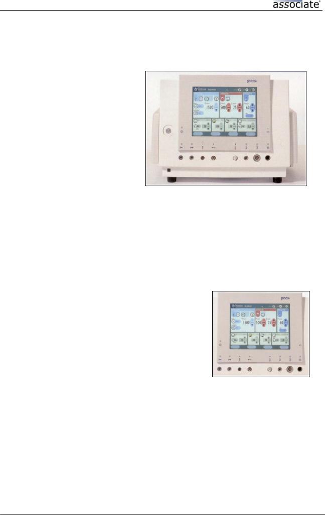
Figure 2.1b illustrates the ASSOCIATE® COMPACT in block diagram form. The following sections of this chapter cover in detail the principle of operation of each functional module.
Service Manual |
Page 11/63 |
30203300-G |
D.O.R.C. International b.v.
2.2 User Interface
The ASSOCIATE® provides all necessary functions to perform phaco and vitrectomy surgery. The unit includes nine separate function modules, a remote control and a footswitch.
The function modules are :
Phaco-Emulsification / Fragmentation Module
Vitrectomy Module
Scissors Module
Irrigation/Aspiration Module
Diathermy Module
Triple Port Illumination Module
Air Module
VFI Module
VFE Module
These modules may be used together, or combination. Functions of some of the modules are interactive. For example, when the Phaco & Vitrectomy Module is activated, the Irrigation/Aspiration Module is activated as well. A footswitch provides a convenient way of controlling several modules at once.
To provide the ophthalmic surgeon the optimum convenience, the ASSOCIATE® is equipped with a dual pump system, Peristaltic and Venturi selectable for both anterior and posterior surgery.
The ASSOCIATE® is prepared for a future combination with an Auxiliary Unit.
Color LCD Display and Touch Screen
The display and touch screen show the icons and buttons with which the user interacts with the system. An icon or button is selected and activated when the user presses that region of the screen where it is displayed. A sterile drape can be used over the touch screen so the ASSOCIATE® can be operated with sterile surgical gloves.
2.3 Description of Phaco
The module can provide linear control of aspiration in combination with both linear, fixed and/or pulsed outputs to a phaco handpiece. This module features continuous auto-tuning. This allows the instrument to maintain constant performance and adjust automatically for changes in loading. When the Phaco-emulsification is activated, the Irrigation/Aspiration Module is also activated.
2.4 Description of Vitrectomy
Service Manual |
Page 12/63 |
30203300-G |

D.O.R.C. International b.v.
The Vitrectomy Module provides outputs for electric and pneumatic high speed vitrectomes. Electric outputs can produce a maximum frequency of 1.500 cuts per minute and Pneumatic outputs can produce a maximum frequency of 2.500 cuts per minute. This module can provide linear or fixed control of vitrectomy cutting in combination with linear control of aspiration.
2.5 Description of Irrigation/Aspiration
The I/A mode generates vacuum by a selectable peristaltic or venturi pump.
The I/A mode also provides I/A Min. mode for capsule cleaning, selectable by the ON/OFF switch on the screen.
Constant irrigation ON/OFF is controlled by the ON/OFF switch on the screen or footswitch command. The irrigation flow is regulated by the height of the infusion pole.
The peristaltic pump can produce a maximum vacuum of 500mmHg and max. 50cc/min. flow independently from each other. The Venturi pump can produce a maximum vacuum of 500 mmHg. The upper limit can be selected using the preset control buttons. The actual vacuum level can be controlled up to the maximum, using the Footswitch.
2.6 Description of Diathermy
The Diathermy Module provides selective burn placement for anterior and posterior segment surgery. The diathermy energy is produced by a crystal-controlled solid-state oscillator. The output is regulated so that the diathermy energy remains constant at the preselected value. The output of the Diathermy Module can be controlled in fixed or linear mode by using the footswitch.
2.7 Description of Triple Port Illumination
The Triple Port Illumination Module is intended to provide intraocular illumination during vitreo retinal surgery. The module includes three light source outlets to use three illumination accessories simultaneously. The light output of the source can be controlled using the On/Off switch and the UP/DOWN selector on the screen. The light module will accept a wide range of D.O.R.C. fiber optic accessories.
2.8 Description of Air module
The Air Module provides an automatic air infusion system. The pressure can be selected on the front panel of the module, and is indicated on the screen. The air is delivered to the tubing set through an extended 0.22µ filter to assure sterility. During operations on the posterior segment of the eye which require fluid-gas exchange, the Air Module provides an automatic injection of sterile air at the preset pressure.
2.9 Description of Viscous Fluid Injection module
The V.F.I. (Viscous Fluid Injection) module has to be used with the 1363-D V.F.I. accessory.
This section provides a way of fixed or linear controlled injection of viscous fluids. The system can inject viscous fluids with a viscosity of up to 5.000 centistokes.
Service Manual |
Page 13/63 |
30203300-G |

D.O.R.C. International b.v.
2.10 Description of Viscous Fluid Extraction Module
The V.F.E. Module generates a vacuum by Venturi or Peristaltic pump which provides aspiration to remove intraocular viscous fluids.
The aspiration source can produce a maximum vacuum of 500 mm Hg. In case of peristaltic aspiration, max. aspiration flow can be set at 50cc/min and 600 mm Hg. The upper limit of the vacuum or aspiration flow can be selected using the preset UP/DOWN buttons. The actual vacuum level can be linear controlled, up to the maximum, using the Footswitch # 9.
Service Manual |
Page 14/63 |
30203300-G |

D.O.R.C. International b.v.
Section 3 - Maintenance Instructions
3.1 General Information
Warnings.
Before servicing, please read the information given in the chapter "WARNINGS" of this manual.
Technical assistance
Assistance with servicing is available from D.O.R.C. International Service department either by letter to the following address or by Facsimile or Telephone.
Returns for repair or calibration
To return the equipment to the D.O.R.C. Service Department, a written description including the following information must accompany all returned units:
1.The customer name, address and telephone number.
2.The customer account number.
3.A description of the problem or service desired.
4.The return authorization number.
Returned products should be shipped including footswitch and any handpiece which may be associated with the fault.
Recommended tools and test equipment. |
|
|
ITEM |
SPECIFICATION |
|
1. |
Auto-Ranging Multimeter |
Fluke Model 77 or equivalent. |
2. |
Scopemeter |
Fluke model 99 or equivalent. |
3.Miniature Inspection Light
4.Inspection mirror
5.Set of Flat-tip Screwdrivers
6. RF Voltmeter |
DTS600 |
Introduction and applicability of this manual.
The service manual give the information required to maintain and repair the ASSOCIATE®. In order to understand this manual it is necessary to have a complete understanding of the functions of the ASSOCIATE®. This information can be obtained from the Instruction Manual of the ASSOCIATE®. Usually field service for Phaco module and Diathermy module is limited to swapping the suspected circuit boards, swapping compressed air components, measuring units etc.
Depending on the capabilities of the service facility, some repairs may not possible ; e.g. troubleshooting the main modules of the ASSOCIATE® without proper test equipment and qualified personal. In such cases the defect parts or the complete ASSOCIATE® should be send to D.O.R.C. International b.v.
Service Manual |
Page 15/63 |
30203300-G |

D.O.R.C. International b.v.
3.2 Warnings
A warning indicates a potentially harmful situation to yourself or others.
Electric shock hazard
The ASSOCIATE® contains high voltage circuits.
After performing any repair, calibration procedure performs a final electrical safety check and leakage current test.
Unplug the power cord before cleaning or servicing the unit. Should the power cord or plug become cracked, frayed, broken or otherwise damaged, it should be replaced immediately.
Do not touch any exposed wiring or conductive surface, while the cover is off and the unit is energized. The voltages present, when electric power is connected to the ASSOCIATE®, can cause injury or death.
Never wear a grounding wrist strap when working on an energized unit. The operator should now perform any servicing except as specifically stated in the Instruction Manual.
Do not, under any circumstances, perform any testing or maintenance on medical instruments, while they are being used to monitor a patient.
Always turn ASSOCIATE® OFF before cleaning.
Explosion hazard
Never use this ASSOCIATE® in the presence of flammable aesthetics.
EMC between ASSOCIATE® and other devices. It is important to install and use the equipment in accordance with the instruction in order to prevent interference with other devices in the vicinity.
Cautions
A caution indicates a condition that may lead to equipment damage or malfunction.
Electrostatic discharge through the printed circuit boards will damage the components of the ASSOCIATE®. Handle all circuit boards (replacements and defective) by their non-conductive edges and use anti-static containers, when transporting them. Before servicing the equipment, ground yourself and the tool to discharge any accumulated static charge, by wearing a static tool wrist strap. Use hospital-grade grounded receptacle only.
Servicing of this product, in accordance with the Service Manual, should never be undertaken in the absence of proper tools, test equipment and the most recent revision of the Service Manual, which must be clearly and thoroughly understood.
Do NOT apply tension the line cord. Check rear panel voltage setting before connecting the ASSOCIATE® to AC main power.
NEVER IMMERSE THIS UNIT IN LIQUID !!!
Service Manual |
Page 16/63 |
30203300-G |

D.O.R.C. International b.v.
3.3 Recommended Spare Parts
D.O.R.C. International b.v. recommends that you keep the following parts on hand. If a problem develops, this will allow you to return the unit to service quickly.
Part no. |
Part |
Description |
1266-A2 |
Light bulb - Halogen |
24V,150 Watt |
|
Fuse-110/120/230/240VAC~ |
6,3 A slow-blow |
|
Fuse-110/120/230/240VAC~ |
3,15 A slow-blow |
|
Fuse light 10 amp |
12 A |
|
Fuse Trafo secondary |
|
|
Fuse Trafo secondary |
6,3 A |
|
O-ring |
|
|
|
|
Table 7 - Recommended Spare Parts
3.4 Periodical Instructions for Preventive Inspection and Maintenance
Periodical instructions for preventive inspection, besides user or operator cleaning instructions (see par. 3.6), are not required.
3.5 Returning the Unit for Repairs
Before returning the unit to D.O.R.C. International b.v. for repairs, please contact the After Sales Department:
After Sales Department D.O.R.C. International b.v. Scheijdelveweg 2
3214 VN Zuidland
The Netherlands
Tel |
: ++31 181 458080 |
Fax |
: ++31 181 458090 |
: sales@dorc.nl |
|
Web-site |
: www.dorc.nl |
Please try to protect the unit as much as possible during shipping. It is best to use the original packaging if it is available.
3.6 User or Operator Instructions for cleaning the ASSOCIATE®
Before cleaning the ASSOCIATE® disconnect the power cord and let the ASSOCIATE® cool down first. The ASSOCIATE® should only be cleaned with a humid (clean or sterile water) towel.
Be aware of liquid running into the ASSOCIATE®.
Service Manual |
Page 17/63 |
30203300-G |

D.O.R.C. International b.v.
3.7 Replacing the Fuses
1.Turn off the power switch on the back of the unit. Unplug the power cord.
2.The fuses are located on the rear of the unit, inside the black box at the point where the power cord is attached. The fuse cover has two tabs. Squeeze these together, and pull the fuse assembly out.
3.Remove the old fuses. Replace them with two new fuses of the same type:
Voltage |
Fuse |
Dimensions |
|
|
|
110/120/VAC~ |
6,3 AT (slow blow) |
5 x 20 mm |
|
|
|
220/240/VAC~ |
3,15AT (slow blow) |
5 x 20 mm |
|
|
|
The fuse type is also listed on the label on the rear of the unit.
4.Plug in the power cord and turn on the power switch on the rear of the unit.
5.Important! If the new fuses fail quickly, there may be something wrong with the unit. Call D.O.R.C. International b.v. for instructions.
Service Manual |
Page 18/63 |
30203300-G |
D.O.R.C. International b.v.
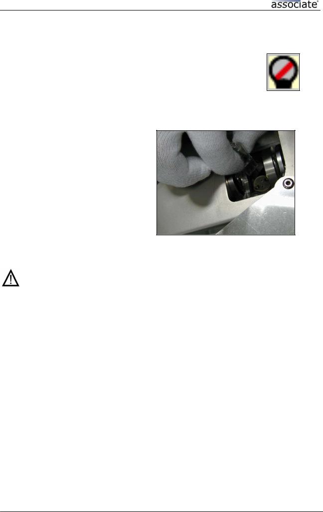
3.8 Changing a Halogen Bulb
In the event of a bulb burn-out, the Illuminator icon is indicating :
The illumination mode automatically switches to the second back-up bulb.
NOTE : At the end of the procedure, it is recommended that the
burned out bulb is replaced so that a back-up light source is always available.
Changing a Halogen Bulb :
1.Unplug the power cord of the ASSOCIATE®. Allow about 5 minutes for the bulb to cool down.
2.Open cover-lid on the left monitor side.
3.Turn inner protection cover to the left to enter light module.
4.Remove the defective bulb excentric from the optical system.
5.Install a new halogen bulb (24 Volt/150 Watt)
6.Close protection cover and cover lid.
7.Plug-in the power cord again.
Warning !
The halogen bulbs used in this unit become very hot when the unit is operating. Before changing the bulb, shut OFF the unit and allow at least 5 minutes for the bulb to cool down. Never touch a hot bulb with your bare fingers. Don’t wear vinyl gloves when working with a hot bulb.
Caution !
Do not touch the mirror and lens near the bulb. Any fingerprints will reduce the amount of light produced by the unit. Remove any fingerprints using a lens cloth and alcohol.
Service Manual |
Page 19/63 |
30203300-G |
 Loading...