


User’s Manual
Version 6.3C
Account Manager Software for Windows
DoorKing, Inc.
120 Glasgow Avenue
Inglewood, California 90301
U.S.A.
Phone: 310-645-0023
Fax: 310-641-1586
www.doorking.com
P/N 1835-066 REV N, 7/13
Copyright 2013 DoorKing, Inc. All rights reserved.

Page 2 1835-066-N-7-13

NOTICE
DOORKING INC. reserves the right to make changes in the product described in this manual at any time
and without notice or obligation of DoorKing Inc. to notify any persons of any such revisions or
changes. Additionally, DoorKing Inc. makes no representations or warranties with respect to this
manual. This manual is copyrighted, all rights reserved. No portion of this manual may be copied,
reproduced, translated, or reduced to any electronic medium without prior written consent from
DoorKing Inc.
Companies, apartment complexes, names, and data used in the examples in this manual are fictitious unless
otherwise noted.
END-USER LICENSE AGREEMENT FOR DOORKING SOFTWARE
IMPORTANT – READ CAREFULLY: This DoorKing End-User License Agreement (EULA) is a legal
agreement between you (either an individual or entity) and DoorKing, Inc. for DoorKing software
products which includes computer software programs and may include associated media, printed
materials or other electronic documentation (SOFTWARE PRODUCT). By installing, copying, or
otherwise using the SOFTWARE PRODUCT, you agree to be bound by the terms of this EULA. If you do
not agree to the terms of this EULA, do not install or use the SOFTWARE PRODUCT.
SOFTWARE PRODUCT LICENSE
The SOFTWARE PRODUCT is protected by copyright laws and international copyright treaties, as well as
other intellectual property laws and treaties. The SOFTWARE PRODUCT is licensed, not sold.
DOORKING, Inc. licenses the DoorKing SOFTWARE PRODUCT for your use only. You assume all
responsibility for the installation, operation and results. You may create copies of the SOFTWARE
PROGRAM. You may not copy the printed materials or other electronic documentation accompanying the
SOFTWARE PRODUCT.
You may not reverse engineer, disassemble or decompile the SOFTWARE PRODUCT nor copy its features
or methods of operation for use in any other program. You recognize that DoorKing’s source code, data,
features and methods of operation are trade secrets belonging to DoorKing.
You may permanently transfer all of your rights under this EULA, provided you retain no copies, you
transfer all of the SOFTWARE PRODUCT (including the media and printed materials) and the recipient
agrees to the terms of this EULA.
Without prejudice to any other rights, DoorKing may terminate this EULA if you fail to comply with the
terms and conditions of this EULA. In such event, you must destroy all copies of the SOFTWARE
PRODUCT and all of its component parts.
LIMITED WARRANTY
DOORKING, INC. warrants that the SOFTWARE PRODUCT will perform substantially in accordance with the accompanying written
materials for a period of ninety (90) days from the date of receipt.
DOORKING, INC. warrants the diskettes on which on which the software is recorded to be free from defects in materials and faulty
workmanship under normal use for a period of ninety (90) days after the date of the original purchase. If during this 90 day period a defect
in the diskette should occur, the diskette may be returned for replacement without charge through your authorized DoorKing dealer. Your
sole remedy in the event of a defect in a diskette is limited to replacement of the diskette as provided above. This remedy is your exclusive
remedy for breach of this warranty. It gives you certain rights and you may have other rights which vary from state to state.
EXCEPT FOR THE EXPRESS WARRANTY ABOVE, THE DOORKING REMOTE ACCOUNT MANAGER (PRODUCT) IS
PROVIDED ON AN "AS IS" BASIS, WITHOUT ANY OTHER WARRANTIES, OR CONDITIONS, EXPRESS OR IMPLIED,
INCLUDING BUT NOT LIMITED TO WARRANTIES OF MERCHANTABLE QUALIT Y, MERCHANTABILITY OR FITNESS FOR
A PARTICULAR PURPOSE, OR THOSE ARISING BY LAW, STAT UTE, USAGE OF TRADE OR COURSE OF DEALING. THE
ENTIRE RISK AS TO THE RESULTS AND PERFORMANCE OF THE PRODUCT IS ASSUME D BY YOU. NEITHER WE NOR OUR
DEALERS OR DISTRIBUTORS SHALL HAVE ANY LIABILITY TO YOU OR ANY OTHER PERSON OR ENTITY FOR ANY
INDIRECT, INCIDENTAL, SPECIAL OR CONSEQUENTIAL DAM AGES WHATSOEVER, INCLUDING BUT NOT LIMITED TO
LOSS OF REVENUE OR PROFIT, LOST OR DAMAGED DATA OR OTHER C OMMERCIAL OR ECONOMIC LOSS , EVEN IF WE
HAVE BEEN ADVISED OF THE POSSIBILITY OF SUCH DAMAGES OR TH EY ARE FORESEEABLE; OR FOR CLAIMS BY A
THIRD PARTY. OUR MAXIMUM AGGREGATE LIABILITY TO YOU, AND THAT OF OUR DEALERS AND DISTRIBUTORS
SHALL NOT EXCEED THE AMOUNT PAID BY YOU FOR THE PRODUCT. THE LIMITATIONS IN THIS SECTION SHALL
APPLY WHETHER OR NOT THE ALLEGED BREACH OR DEFAULT IS A BREACH OF A FUND AMENTAL CONDITION OR
TERM, OR A FUNDAMENTAL BREACH. SOME STATES / COUNTRIES D O NOT ALLOW THE EXCLUSION OR LIM ITATION
OF LIABILITY FOR CONSEQUENTIAL OR INCIDENTAL DAMA GES SO THE ABOVE LIMITATIONS MAY NOT APPLY TO
YOU.
1835-066-N-7-13 Page 3

TABLE OF CONTENTS
Section 1 – Introduction
1.1 Installation Guidelines – All Systems........................................................................................................7
1.2 Getting Started
1.2.1 Windows 8, Windows 7, Windows Vista or Windows XP Install ..............................................8
1.2.2 File Information.........................................................................................................................9
1.2.3 Security Levels.........................................................................................................................10
1.2.4 Elevator Control........................................................................................................................10
1.2.5 Hold Open Time Zones............................................................................................................10
1.2.6 Holiday Schedule .....................................................................................................................11
1.2.7 Transactions.............................................................................................................................11
1.2.8 Live Transactions.....................................................................................................................11
1.2.9 Live Streaming .........................................................................................................................11
1.2.10 Anti-Pass Back.........................................................................................................................11
1.2.11 Users........................................................................................................................................11
1.2.12 Port Configuration ....................................................................................................................11
1.2.13 Clock Setting............................................................................................................................12
1.2.14 Prior to Programming ...............................................................................................................12
1.2.15 Start the Program.....................................................................................................................12
1.2.16 Series Column..........................................................................................................................12
Section 2 – Account Management
2.1 Account Information..................................................................................................................................13
2.1.1 Creating User Types ................................................................................................................14
2.1.2 Creating a New Account...........................................................................................................15
2.1.3 Editing Account Information .....................................................................................................16
2.1.4 Deleting Accounts ....................................................................................................................16
2.2 Share Information Feature........................................................................................................................17
2.3 Communication Port Configuration
2.3.1 Communication Configuration..................................................................................................18
2.3.2 Server Login / Registration.......................................................................................................18
Section 3 – System Management
3.1 Entry Panel Programming ........................................................................................................................19
3.1.1 Entry Panel Setup ....................................................................................................................20
3.1.2 Communication Setup..............................................................................................................20
3.1.3 Tone Open Numbers................................................................................................................20
3.1.4 Entry Codes..............................................................................................................................21
3.1.5 Miscellaneous Setup Items ......................................................................................................22
3.1.6 System Message......................................................................................................................22
3.2 Relay Numbering and Control..................................................................................................................23
3.2.1 Labeling Relays with Tracker Disabled....................................................................................24
3.2.2 Labeling Relays with Tracker Enabled.....................................................................................25
3.3 Relay Hold Open Time Zone Programming
3.3.1 Creating Relay Hold Time Zones.............................................................................................26
3.3.2 Applying Relay Hold Time Zones.............................................................................................27
3.4 Holiday Schedule......................................................................................................................................28
3.5 Security Levels.........................................................................................................................................29
3.5.1 Planning Security Levels..........................................................................................................30
3.5.2 Creating Security Levels ..........................................................................................................31
3.6 Anti-Pass Back (APB)
3.6.1 True Anti-Pass Back.................................................................................................................33
3.6.2 Facility Counter ........................................................................................................................33
Page 4 1835-066-N-7-13

Re-Sync Operations.................................................................................................................33
3.6.3
3.6.4 Programming Anti-Pass Back ..................................................................................................34
3.7 Facility Codes and Device Association
3.7.1 Facility Codes...........................................................................................................................35
3.7.2 Device Association...................................................................................................................36
3.7.3 Mass Enable ............................................................................................................................37
3.8 Elevator Control
3.8.1 Planning Elevator Control / Security Levels.............................................................................38
3.8.2 Programming the Relay / Elevator Control Table.....................................................................39
3.8.3 Programming Security Levels with Elevator Control................................................................40
Section 4 – Database Management
4.1 User (Resident) Information .....................................................................................................................45
4.1.1 Adding Resident (User) Information.........................................................................................46
4.2 Assigning Device Codes ..........................................................................................................................48
4.3 Elevator Reference
4.3.1 Programming the Elevator Reference Table............................................................................49
4.3.2 Assigning Elevator Reference to Residents.............................................................................50
Section 5 – Data Transfer / Reports
5.1 Transfer Now
5.1.1 Send Data Now........................................................................................................................52
5.1.2 Receiving Data Now.................................................................................................................53
5.1.3 Receiving Transactions............................................................................................................54
5.2 Scheduled Transfers
5.2.1 Scheduling Transfers ...............................................................................................................55
5.3 Viewing / Reporting Transactions
5.3.1 Viewing Transactions and Reports ..........................................................................................56
5.3.2 Viewing Live Transactions .......................................................................................................58
5.3.3 Creating Transaction Reports ..................................................................................................59
5.3.4 Exporting Reports ....................................................................................................................59
5.4 Live Streaming..........................................................................................................................................60
5.4.1 Output Destinations..................................................................................................................60
5.4.2 Output Format..........................................................................................................................61
5.5 Log Files...................................................................................................................................................62
5.6 Exporting / Importing Database Files
5.6.1 Exporting Data .........................................................................................................................63
5.6.2 Importing Data in CSV Format (Microsoft Excel) .....................................................................64
5.6.3 Main Frame Import...................................................................................................................66
Section 6 – Appendix
6.1 Backup and Restore
6.1.1 Backup .....................................................................................................................................69
6.1.2 Restore.....................................................................................................................................69
6.2 Trouble Shooting
6.2.1 Modem .....................................................................................................................................70
6.2.2 Entry System............................................................................................................................70
6.2.3 Phone Line...............................................................................................................................70
6.2.4 Date / Time...............................................................................................................................70
6.2.5 Computer System Information Form........................................................................................71
6.2.6 Error Messages........................................................................................................................72
6.3 Glossary ...................................................................................................................................................73
Security Level Planning Guide .................................................................................................................75
1835-066-N-7-13 Page 5

Page 6 1835-066-N-7-13

SECTION 1 - INTRODUCTION
The DoorKing Remote Account Manager for Windows Version 6.3 is a powerful, flexible and easy to use
computer program that allows you to manage access control in a variety of controlled access applications
including apartment complexes, gated communities, apartment and condominium building's, college resident
halls, office buildings, factories, industrial sites, etc. Use this program with the DKS models 183 3, 1834, 1835
and 1837 Telephone Entry and Access Control Systems, and with the model 1838 Multi Door Card Access
System. Programming the access system can be via the DK IMServer, an internet connection, LAN, modem or
RS-232 protocol.
This software program will allow you to program and manage up to 9,999 different 1 833, 1834, 1835, 1837 or
1838 systems (called accounts), each with up to 16 differ ent controlled access points (using Tracker e xpansion
boards), each using a variety of control technologies (Card, RF ID, PIN, etc.) for up to 3000 individuals, and can
accommodate up to 8000 unique device (Card, RFID, PIN) codes. You can also manage guest and resident
elevator usage for each account for up to eight (8) elevators serving up to 64 floors each for those applications
where elevator control is a necessity. NOTE: The 1834 does n ot ha ve card, securit y le vel, anti-pass back o r
elevator control capability, and cannot be interfaced with Tracker expansion boards.
IMPORTANT! Prior to creating a new account, you will be prompted to choose the "series" number of
the circuit board in the entry system that you are going to program. This software program and user
manual can only be used with 40E and 30 series circuit boards.
The information in this manual describes the use of the DoorKing Remote Account Manager for Windows,
versions 6.3 only. For information relating to the installation of th e telephone entry or access control systems,
refer to the respective installation and maintenance manual shippe d with the system. For information relating to
the Tracker™ expansion boards, refer to the separate manual for these boards. For information about the
elevator control board, refer to the Elevator Control Installation manual.
1.1 Installing the Software
Here are the minimum requirements needed to install and use the DoorKing Remote Account Manager for
Windows.
A PC running Windows 8, Windows 7, Windows Vista or Windows XP.
An internet connection (if using this method to send and receive data to the access system).
An RS-232 port or USB to Serial Adapter (for direct wired connection).
An Ethernet connection if using TCP/IP to connect to the access system.
A mouse.
A voice/data modem (if using this method to send and receive data to the access system) plus a
telephone line connected to the modem.
A CD Drive or download the software from doorking.com.
The DoorKing Remote Account Manager Software (This software program is not designed to operate in
a network environment).
Some computers with an internal modem will not communicate with the 1833, 1834, 1835, 1837 and 1838
systems. If you have difficulty communicating using an internal modem, we suggest you use the internet
connection option to allow the DKS server to communicate with the access system.
1835-066-N-7-13 Page 7

1.1.1 Installing from the CD
Stop all running programs. Insert the DKS CD in the CD dr ive. If the setup program does not st art automaticall y,
follow the steps below.
1. Select RUN.
2. Enter: E:DKSETUP (use the letter of your CD drive) in the command line and then click OK.
3. Follow the on screen instructions.
1.1.2 Download from Internet Site
If you have downloaded the software from our internet site:
1. Double click DKSETUP.EXE (from your Downloaded Program Files Folder)
2. Follow the on screen instructions.
1.1.3 File Information
When you installed the DoorKing Remote Account Manager, the software automatically created a folder
(directory) named DoorKing in the Program Files folder. Each account that you establish creates a sub-folder in
the DoorKing Account Manager folder starting with ACCT0000. The respective account files are then stored
under the account sub-folder.
Windows XP
C:
PROGRAM FILES
DOORKING 32
ACCT0000
ACCT0001
ACCT0002
Windows Vista / Windows 7 / Windows 8 – Just Me
Program Files Data Files
C:
PROGRAM FILES
DO
ORKING
DOORKING ACCOUNT
MANAGER
C:
Windows Vista / Windows 7 / Windows 8 – Everyone
C:
USERS
PUBLIC
PUBLIC DOCUMENTS
DOORKING
DOORKING ACCOUNT
MANAGER
PROGRAMDATA
DOORKING
DOORKING ACCOUNT
MANAGER
ACCT0000
ACCT0001
ACCT0002
ACCT0000
AC
CT0001
ACCT0002
Page 8 1835-066-N-7-13
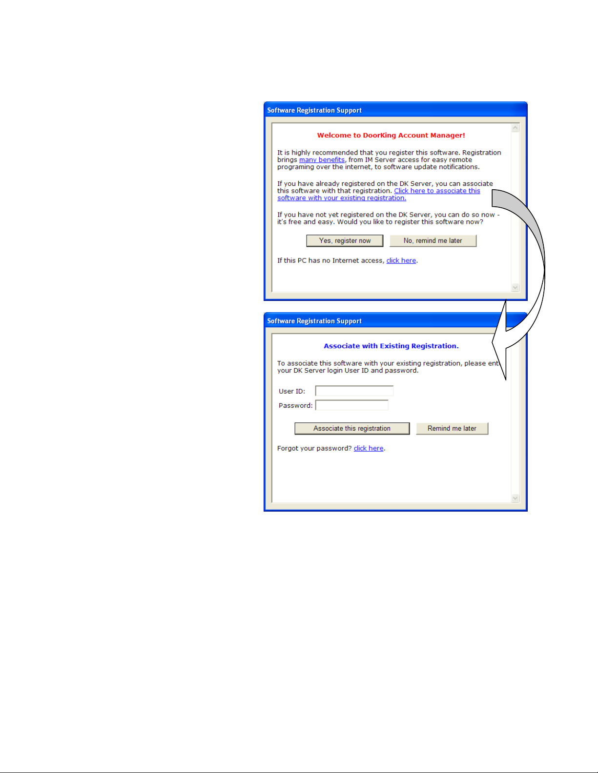
1.1.4 Software Registration with an Existing DK Server Registration
When you first open the Account Manager software, you will receive a prompt to register the software.
Already Registered
If you already have a registration from an
earlier version of the Account Manager
software, you do not need to create
another. Use “Click here to associate
this software with your existing
registration” to continue.
ou have never registered any
(If y
software on the DK Server, go to
section 1.1.5.)
Login
Enter your existing user name and
password and click “Associate this
Registration.”
1835-066-N-7-13 Page 9
1.1.5 New Registration
To register the software, we highly recommend that your PC has an internet connection. This will greatly simplify
the registration process.
Internet Connection
If the PC does have an internet
connection (recommended), click the
“Yes, register now” button to create a
ew registration.
n
If the PC does not have an internet
connection, you can click “this PC
ternet connection” to continue.
in
has no
Page 10 1835-066-N-7-13
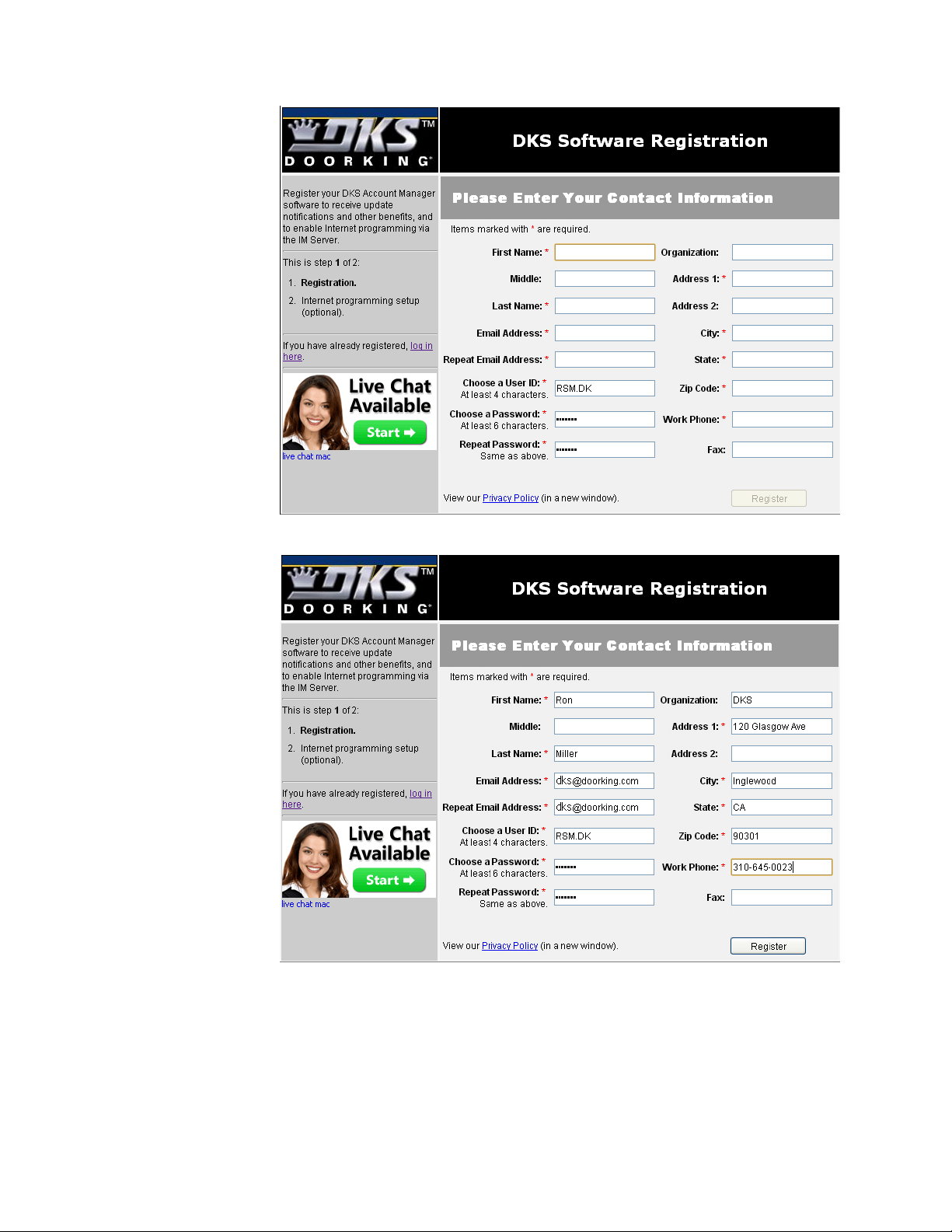
Once a user ID and
password are
created, your web
browser will open to
the DKS Software
R
egistration page.
Complete the form
to register
the
software. Your
user name and
password you
entered will already
be filled in for you.
Click the “Register”
utton
b
nished.
fi
when
1835-066-N-7-13 Page 11
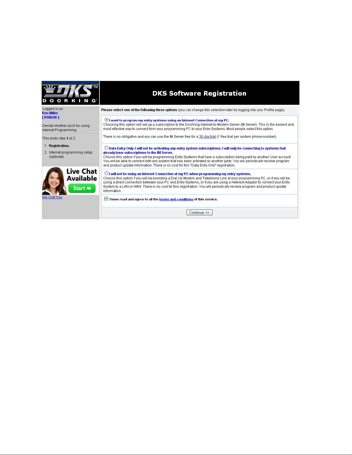
Select the option that best describes what you want to do, then click “Continue”.
If you select either option 2 or 3, the registration of the software is complete.
If you selected option 1(using the IM Server to program your entry system), you will then be directed to
activate the entry system in the IM Server. See section 1.1.6.
Page 12 1835-066-N-7-13
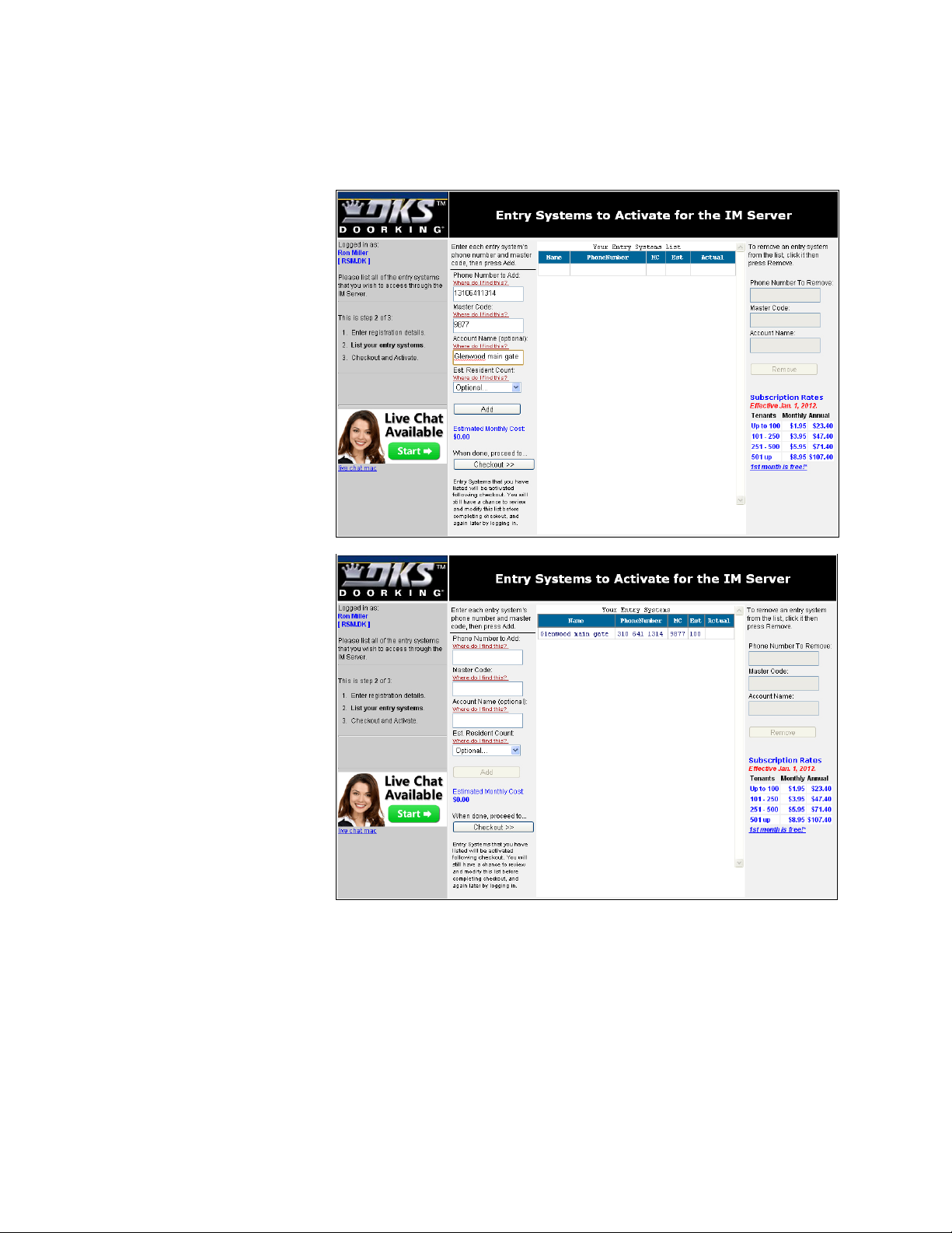
1.1.6 Entry System Activation
If you have chosen to use the DoorKing IM Server to program your entry system, then the system must be
activated in the IM Server first. Enter the following information in the spaces provided on the left hand side of the
system activation screen.
Enter the 11-digit telephone
number (1 + Area Code +
Number) of the phone line
connected to the entry
system. This information is
required.
Enter the 4-di
system Master Code
information is required.
Enter a descriptive name for
the system (Optional).
Enter the number of
residents that the entry
system serves (Optional).
Click “Add” when completed.
he entry system will be
T
shown in the Entry Systems
List.
Repeat the above steps to
add additional entry systems,
or click “Checkout.”
git entry
. This
1835-066-N-7-13 Page 13
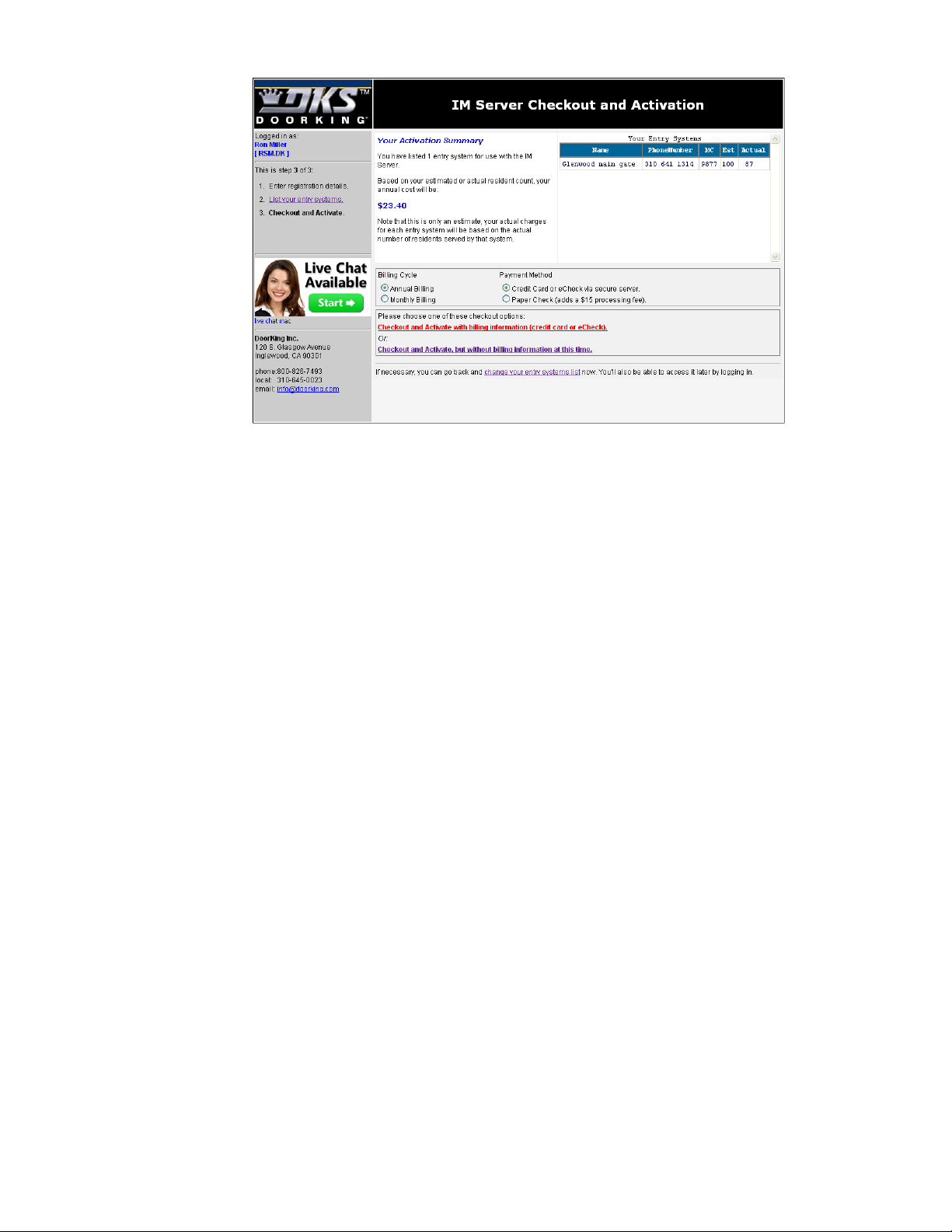
The checkout
screen shows the
estimated annual
cost of using the IM
Server to program
your entry system.
Select the bi
lling
cycle and payment
method.
To finish, choose
one of the checkout
options.
Checkout and Activate with Billing Information (credit card or eCheck)
This choice completes the activation of your system. You will receive the first 30 days free and subsequent
payments (either monthly or yearly) are automatic.
Checkout and Activate, but without Billing Information at this time
This choice activities your system for the 30 day free trial period. After the 30 day free trial period, you will no
longer be able to use the IM Server until billing information is received.
Page 14 1835-066-N-7-13

1.2 Getting Started
1.2.1 Security (Permission) Levels
Security (permission) levels allow you to set individual door/gate access times for residents using a wiegand
device (Card, RFID, PIN, etc.). An example of this would be a gated apartment community that has a vehicula r
entry gate, a pedestrian access gate, a pool gate, a laundry room door, tennis court gate, office door, etc., where
entry is controlled by a card reader. Security levels can be created that would allo w residents access throu gh the
vehicular entry gate and pedestrian access gate 24 hours a day, 7 days a week, access to the pool and tennis
court from 9:00 AM - 10:00 PM 7 days a week, access to the laundry room 7:00 am - 11:00 PM 7 days a week,
and access to the office 9:00 AM - 6:00 PM Monday through Friday only.
Security levels are not assigned to the access control device. T hey are assigned to the individual user. In this
manner, different security levels can be created allowing different access times to different users through a single
access point. For example, this could be applicable in a controlled office (or factor y) environment where different
employees have different working hours.
There are 31 security levels available in the software program. The first two (Security Level 00 and 01) are
factory set and are not programmable. Security Level 00 (SL00) will deny access at all controlled access
locations to the user(s) that it is assigned to. An example of using SL00 would be a tenant in an apartment
building who has been evicted and is no lo nger all owed entr y to the building or any other contro lled acc ess point
within the building. Security Level 01 (SL01) is the opposite of SL0 0, and will allow access to users that it is
assigned to 24 hours a day, 7 days a week. An example of using SL01 would be for management or
maintenance personnel who need to have full access to ALL locations at ALL times.
The remaining 29 security levels (SL02 - SL30) allo w you to setup four different time zones for each level, and
allow you to select the controlled access point(s) that it applies to. In the example given in paragraph 1 above,
four different time zones where created under a single security level, and then the controlled entr y point(s) that
the time zone applies to were selected. The security level was then assigned to the individual residents.
When anti-pass back is in use, residents must be assigned a security level between 02 and 27. These
security levels can be limited by the APB feature when it is turned on. Security levels 01, 28, 29 and 30
are not limited by APB.
Note: When using the Holiday schedule feature, the software will automatically c onvert Time Zone 4 in each
security level to conform to the Holiday Schedule. TZ-4 on the security level pag e will then be labeled HOL.
Security levels are not available on the Model 1834.
1.2.2 Elevator Control
The elevator control feature determines which elevator(s) in a building a guest or res ident will be allowed to use,
and to which floor(s) the resident or guest will be allowed to go to, under certain controlled access con ditions. In
its most common use, when a resident grants access to a guest in a high rise apartment building, the system will
call the designated elevator(s) to the ground floor, and then only the floor button that the resident resides on will
be active in the elevator(s). This prevents the guest from accessing other than the designated elevat or(s), or
from going to unauthorized floors.
Elevator control can also be applied to residents to control which elevator( s) they can use and to which floor(s)
they are allowed access too. In this application, a card re ader is installed inside the elevator(s) car. When the
resident enters the elevator, they must use their access card to "turn on" the elevator buttons. The buttons that
will be turned on are set in the software. Security levels can also be applied in this application. As an example,
suppose a resident lives in a high-rise apartment bui lding. On the 20th floor of this building is a workout room
that is only open 7 days a week from 6:00 AM to 11:00 PM only. Elevator control and security level c ontrol can
be employed to allow residents access via the elevator to the workout room at the designated days and time s
only.
Note: Elevator control is not available on the Model 1834.
1.2.3 Hold Open Time Zones
Seven different time zones can be created to "Hold Open" th e door or gate at a controlled access point. An
example of using this feature would be to hold open a vehicular access gate during "r ush hour" traffic, unlock an
office door during normal working hours, etc. Hold open time zones can be applied individually, or in any
combination to each controlled access point(s). The eight hold open time zone is labeled HOL for “Holiday.”
This time zone takes precedent whenever a “Holiday” date is present.
1835-066-N-7-13 Page 15

1.2.4 Holiday Schedule
32 different “Holidays” can be set up in the software program. Whenever a holida y is present, the software will
look first at the HOL schedules in the Hold Open Time Zones and the Security Levels. For e xample, if a holida y
is created for Christmas Day, the software will revert to the HOL hold-open time zone on December 25th.
1.2.5 Transactions
Transactions are automatically saved each time that they are received from the 1833, 1834, 1835, 1837, or
1838. Each time transactions are received, the software will automatically create a file name for them starting
with TRANS0000. The file number will increase sequentially to a m aximum TRANS9999. When 9999 files have
been created, prior to receiving the next transaction file, the software will over write the old TRANS0000 file with
the new transaction information and will delete file TRANS0001. The next transaction file that is received will be
stored in the now empty TRANS0001 file and the information in TRANS0002 will be deleted to make room for the
next transaction file. This sequence repeats itself sequentially.
Transactions are stored under their respective account sub-folders. This prevents transactions from on e account
being mixed up with transactions from another account. Each account can therefore have up to 9999 transaction
files stored as described above.
1.2.6 Live Transactions
Transactions can be viewed on the computer screen as they happen. Live transactions require an RS-232
connection between the PC and the access controller or L AN option and a TCP/IP connection to the controller
using a DKS TCP/IP connection kit (P/N 1830-175).
1.2.7 Live Streaming
Live streaming provides data that can be captured and used by other software applications. Live streaming
requires an RS-232 connection (use P/N 1818-040 cab le) between the PC and the access controller, or LAN
option and a TCP/IP connection to the controller using a DKS TCP/IP connection kit (P/N 1830-175).
1.2.8 Anti-Pass Back
The anti-pass back feature in this software program is TRUE anti-pass back. TIMED anti-pass back is not
available. True anti-pass back can be set up in one of three different modes. PASSIVE anti-pass back will
record APB violations but will allow the offending card access. ACTIVE anti-pass back will record APB violations
but will not allow the offending card access. TRAP anti-pass back will record the APB violation, and will allow the
card access at the entry, but deny access at the exit. Anti-pass back is not available on the 1834.
1.2.9 System Administrator / Data Entry Users
There are two types of users that can be set up with passwords. The system Administrator has access to all
the features of the software program and can set up sec urity levels, hold op en times, elevator contro l, etc. Data
Entry users are limited to daily tasks such as adding or removing resident names and sending data to the
system.
System Administrators and Data Entry users are created in the Log In screen which is accessed by the USE RS
button on the account screen. If users are set up, the first one MUST be an Administrator. Multiple
administrators and users can be set up.
1.2.10 Port Configuration
If using a modem to send and receive data, the software will automatic ally set the mod em to operate under COM
2, 2400 Baud rate, and will install a set-up string that is common to most modems. If your modem is installed on
another com port, or if you need to enter any special set-up strings, click the CONFIG PORTS button on the
accounts screen. The port configuration window will appear and allow you to make the necess ary adjustments,
or use the auto-config button that will set up the software to respond to your modem installation.
If using the DKS server option to send and receive data, click the Test Server Connection button to i nsure that an
internet connection is made between your computer and the DKS server.
Page 16 1835-066-N-7-13

1.2.11 Clock Setting
Each time contact is made with the entry system from the computer, the clock / calendar in the entr y system is
automatically updated to match the clock information from your PC. Be sur e that your co mputers c lock / cal endar
is set to the correct time and date.
1.2.12 Prior to Programming
The DoorKing Remote Account Manager can manage up to 10,000 separate accounts. By definition, an
"account" is any 1833, 1834, 1835, 1837 or 1838 system that you are going to program with this software. Each
unit must have a unique account name set-up for it, even if the unit is sharing the phone line with another
DoorKing system. If this is the case, you must be sure that the master codes of each unit sharing the line are set
differently. You must also set the software for multiple systems sharing a line by going to the SYSTEM INFO
screen and clicking the YES button next to the multiple systems line.
The following hardware (entry system) parameters cannot be set with the software. These parameters must be
set and programmed into the entry system from the system keypad, or they are factory set limits or features
which cannot be changed remotely. The entry system shoul d be tested to be sure that it is oper ating properly. It
is very important that the phone line connected to the entry system is free of any hum, noise, or other
interference that could cause modem communication problems. Refer to the installation and maintenance
manual that was included with the 1833, 1834, 1835, 1837 or 1838 system to program the following parameters.
1. The system Master Code (default is 9999).
2. 10 or 255 Area Codes (default is 255). 255 area codes are available on REV E or higher
circuit boards only. REV D and lower boards have only 10 area codes available.
3. Single or multiple systems sharing the same phone line (default is single).
4. Match the memory size of the chips sent with the unit (default is 3000). The memory size
cannot be set from the software program.
5. Call-up operation (default is OFF).
1.2.13 Start the Program
The account screen is the main screen that you come to after entering the program. T his is where most of your
work will be done after you have set-up your account(s), programmed your system information and entered your
resident data. From the account screen, you will be able t o program the entry system, receive information from
the remote system, and receive transactions to your PC.
To use the DoorKing Remote Account Manager to program your entr y systems, you will perform the following
three basic steps.
1. Create an account for the access system.
2. Enter the access system information.
3. Enter the resident (user) data.
1.2.14 Series Column
The last column on the account screen is the SERIES column and is indicated by the letter S. This column will
indicate either”30” or "4E" depending on which series control board was selected when the account was created.
1835-066-N-7-13 Page 17
SECTION 2 – ACCOUNT MANAGEMENT
To begin using the DoorKing Remote Account Manager to program your 1833, 1834, 1835, 1837, or 1838
systems, you must first create an ACCOUNT under which all the relevant account information (resident user
data, transaction files, etc.) will be stored.
By definition, an ACCOUNT must be created for every 1833, 1834, 1835, 1837 or 1838 system that will be
programmed with the Remote Account Manager software (up to 10,000 accounts can be managed with this
software). Two or more units cannot share the same account name, even if they are sharing the same pho ne
line. However, different accounts may share a common resident database (Section 2.2).
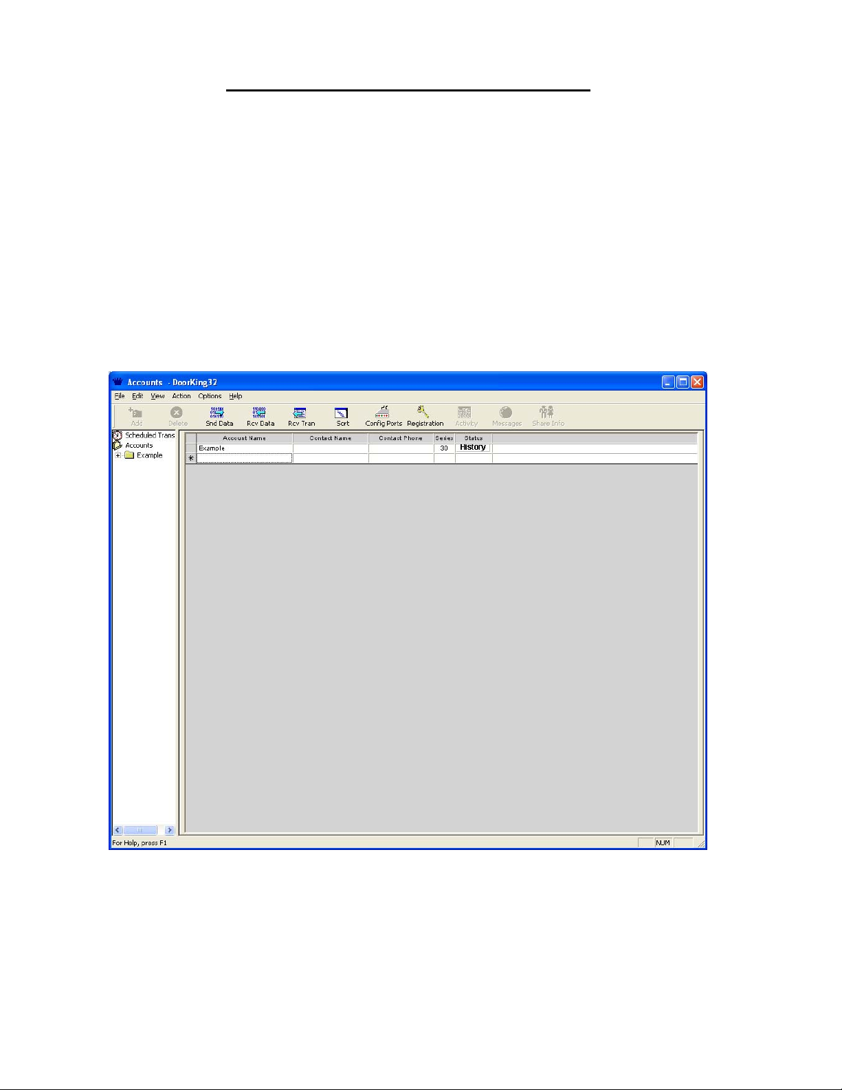
2.1 Account Information
1. Start the Remote Account Manager Software program. While the program is loading, a DoorKing
logo will appear on your screen.
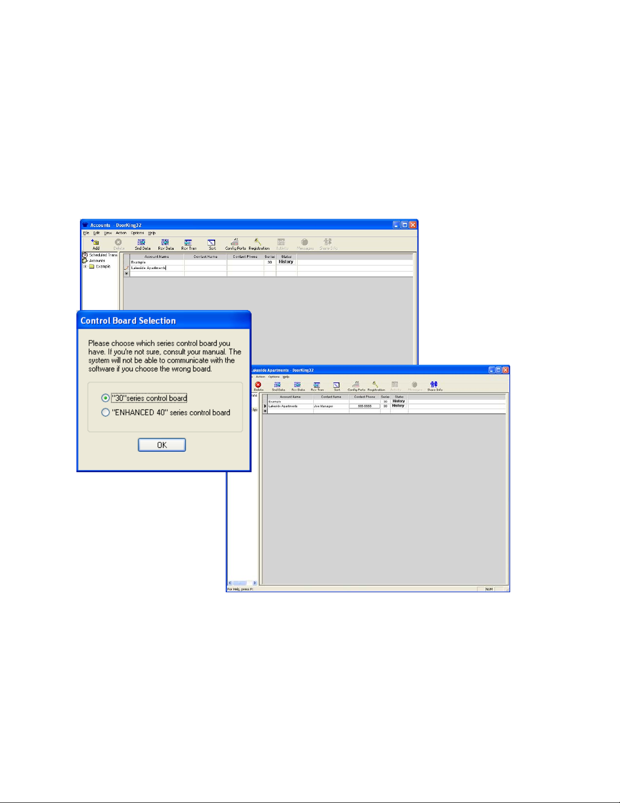
2. The ACCOUNT screen will appear on your screen (fig 1). An account named “Example” has
already been created.
Figure 1
Page 18 1835-066-N-7-13
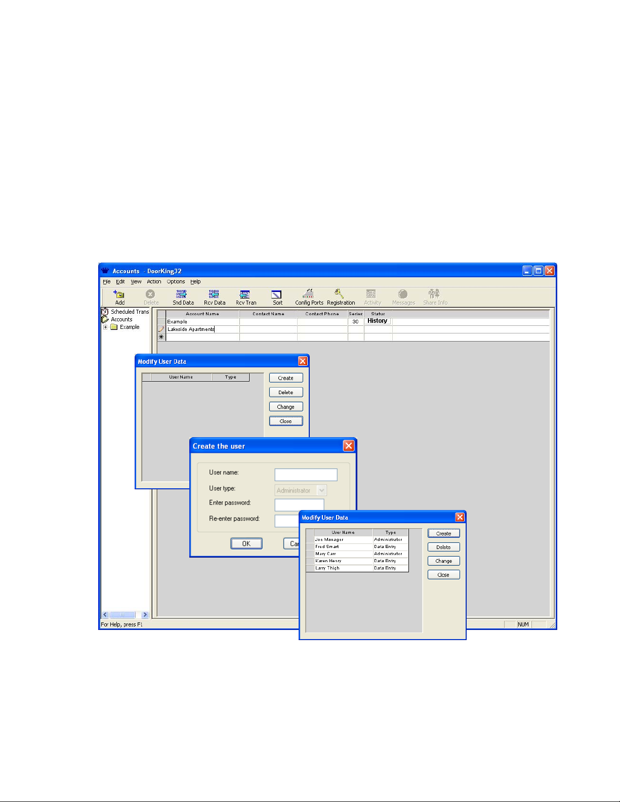
2.1.1 Creating User Types
There are two types of users that can be created in the program; Admi nistrators and Data Entry. Administrators
have access to all levels and features of the program while Data Entry users are limited to daily tasks such as
adding or removing resident names and sending updated i nformation to the acc ess system. When cr eating user
types, the first one MUST be an Administrator. Up to 20 Administrators and 20 Data Entry user types can be
entered in the program.
1. Under OPTIONS, select USER INFO from the pull down menu to display the Modify User window.
2. Click the CREATE button to display the Create the User window.
3. Enter the administrators name and create a password (by s ystem default, this first user MUST be
an administrator; therefore the user type is defaulted to this). Click OK when done.
4. Enter additional names and passwords as required. Once the first name is entered, you can no w
select the user type from the pull down menu. Up to 20 administrators and 20 date entry users can
be created.
5. When complete, click CLOSE on the modify user screen to return to the ACCOUNT screen.
Figure 2
1835-066-N-7-13 Page 19
2.1.2 Creating a New Account
1. With the ACCOUNT screen displayed, place the cursor in the empt y nam e field (b elo w example) or
click the ADD button in the tool bar. Enter the new account name and press the TAB or ENTER
key.
2. The CONTROL BOARD SELECTION window will appear. You must select the type of control
board installed in the system that you are goin g to program. Click “30 Series” to program 1833,
1834, 1835, 1837 or 1838 systems. After selecting the control board series, click OK.
3. Complete your new account information by entering the account manager’s name and phone
number.
4. Repeat steps 1-3 to create up to 99 additional accounts.
5. If more than one account is displayed on the screen, clic k the SORT button to list the accounts in
alphabetical order.
Figure 3
Page 20 1835-066-N-7-13
2.1.3 Editing Account Information
1. Click on the account that you want to edit and make the necessary changes.
NOTE: Editing an account here changes only the account name and contact information. It does nothing to
change any of the resident, system, time zone, security level, etc. information associated with the account.
Figure 4
2.1.4 Deleting Accounts
1. Click on the account that you want to delete.
2. Click the DELETE icon from the tool bar or click FILE then DELETE.
3. A warning will appear asking if you are sure that you want to proceed.
4. Click OK to delete the account or click NO to return to the account screen without deleting the
account.
WARNING: When you delete an account, all the system information and resident data c ontained in the account
folder (sub-directory) will also be deleted. Prior to deleting the acc ount, you may want to copy the account data
onto a CD. This will enable you to restore the resid ent data easily if it becomes necessar y at a later date to reestablish the account.
To copy the data, you can use Windows Explorer to copy the information in the account folder to a CD. Refer to
your Windows User's Manual for instructions on copying files and see section 6.3.2.
You can also use the BACKUP command. Refer to section 6.2.1.
1835-066-N-7-13 Page 21
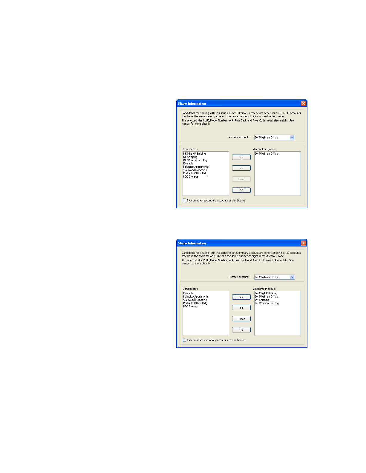
2.2 Share Information Feature
The SHARE INFO feature allows more than one "account" to share its dat abase with other accounts. The share
info feature is useful in applications where there is more than one entry point and the entry points will all have
identical user data. For example, if an apartment complex had a front and rear entry do or (or gate), and an 18 33,
1834, 1835, 1837 or 1838 system was installed on each entry point, the share info feature lets you use and
maintain a single database for both entry loc ation. 30 Series and Enhanced 40 Series accounts can share the
user database with each other, but each account must have the same memory and number of digits in
the directory code set identically. Also, accounts using the APB feature cannot be shared with non-APB
accounts, and vice-versa.
1. From the accounts screen, click the
account name that is the primary account,
then click the SHARE INFO icon in the tool
bar. The share info screen will appear with
the primary account listed in the accounts
group (Fig 5). In the example, DK Mfg
Main Office was selected as the primary
account. Notice that this account name is
shown as the primary account in the upper
right hand corner of the share information
window, and that this account is listed in
the "Accounts In Group" window on the
right side of the screen. To change the
primary account, click the arrow button on
the primary account window, then scroll up
or down and select a new primary
account.
From the candidates list, click the account
2.
that you want to share the primary account
user data base with, and then click the
right ( >>) button to place the account in
the accounts group. In the example, DK
Mfg HP Bldg, DK Warehouse Bldg and DK
Shipping have been placed in the
"Accounts In Group" window (Fig 6).
These accounts will now share the user
database associated with the primary
account - DK Mfg Main Office.
Select other candidate accounts as
3.
required. When complete, click the
CLOSE button.
4. To remove an account from the Accounts
In Group, click on the account you want
removed, and then click the << arrow
button. This will lace the account back in
the candidates list and it will no longer
share the user data with the primary
account.
5. When a candidate account is selected to
share information with a primary account,
the account is removed from the candidate
list, even if a different primary account is
chosen, unless the "Include Other
Secondary Accounts As Candidates"
button is turned ON (X appears in the
button window).
Figure 5
Figure 6
Page 22 1835-066-N-7-13
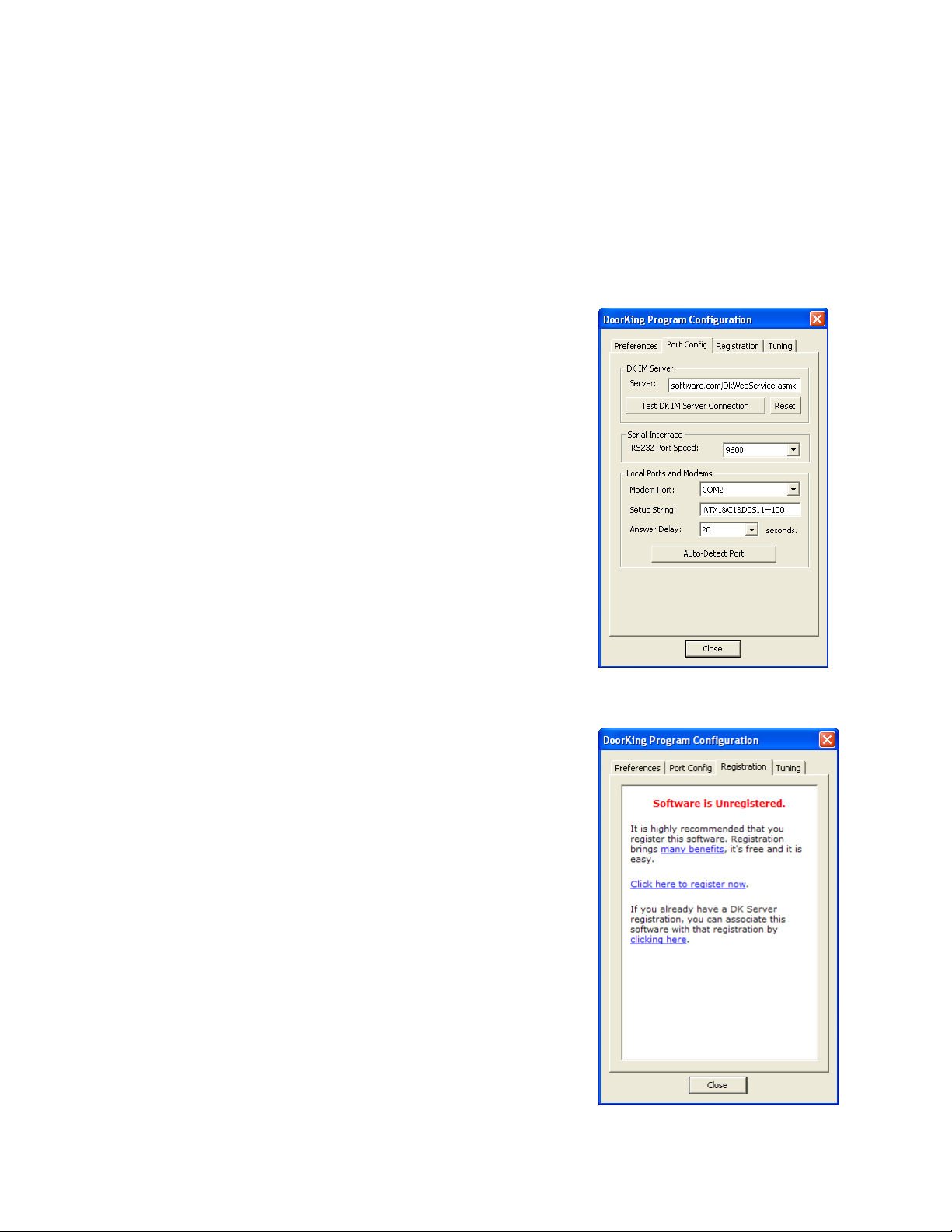
2.3 Communication Port Configuration
If you are using a modem, the Port Config tab in the Program Configuration windo w is provided if you need to
enter any special modem setup strings that may be a pplicable to your modem (refer to the manual that came
with your modem). If you are using a DK IM Server for programming, there is a T est DK IM Server Connection
button that will verify that your computer will connect to the DoorKing server. If you are using the DK IM Server,
you will need to register as a user (see 2.3.2).
IMPORTANT: If using a LAN method to connect, you must have a TCP/IP kit (P/N 1830-175) installed on
the access system control board.
NOTE: Typically, you will not need to make any adjustments to your port configuration, and therefor e no changes
need to be made. You should only make adjustments in these settings if you are experiencing problems in
communicating with the entry system.
2.3.1 Communication Configuration
1. Click the CONFIG PORTS icon in the tool bar. The port
configuration window will appear (Fig 7).
2. Select the Port Config tab.
3. If you are using the DK IM server to send and receive data
(see 2.3.2), click the Test DK IM Server Connection button to
insure your computer can connect to the server.
4. If using an RS232 connection, set the rate to 9600 (default)
or 19200. This rate must match the rate of the device
connected to the RS232 port and the access controller.
Note: 19200 baud rate is only available w ith 30 Series
it boards, REV M (or higher) for 1833, 1834, 1835,
circu
1837, and REV L (or higher) for the 1838. Leave the
baud rate set to 9600 for all other 30 Series circuit
boards.
5. If you are using a modem to send and receive data, make
the adjustments to the port setup as required (refer to your
modem manual) or click the Auto Detect Port button.
6. Click OK to proceed with the changes or click CANCEL to
return to the accounts screen without any changes being
made.
2.3.2 Software/Server Registration
Figure 7
1. If you are going to use a DK IM Server for programming, and
you have not yet registered the software, click “Click here to
register now” link and follow the instructions to register the
software and to create a user registration (see 1.1.5).
Figure 8
1835-066-N-7-13 Page 23
SECTION 3 – SYSTEM MANAGEMENT
Once an account(s) has been created, the access control system information must be programmed. This
information includes setting the entry system parameters, labeling the system relays for each entry point, using
or ignoring card (access device) facility codes, mass enabling device (card, transmitter, etc.) codes, creating
security levels and time zones, creating hold open times, creating a holiday schedule and programming the
elevator control parameters if elevator control is used.
The control board series that was chosen when you first created an account (2.1.2) will affect ho w the entry
panel is programmed. This chapter and the illustrations in it, addresses programming an entry panel with a 30
Series control board. If you are programming an entr y panel with the Enhanced 40 Series board, refer to version
5.6 of this manual.
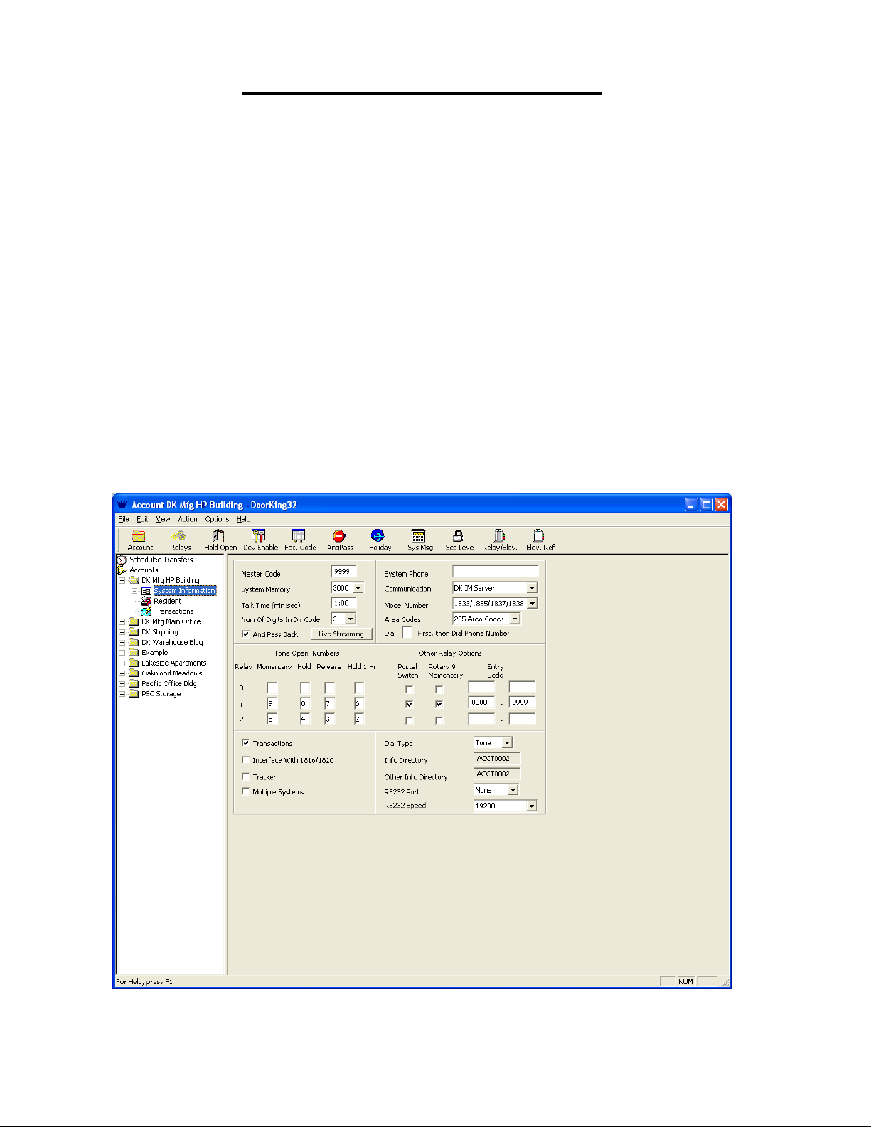
3.1 Entry Panel Programming
The first step in system management is to program the entry panel s yst em param eters. T he entr y p anel can b e a
model 1833, 1834, 1835, 1837 or 1838 depending on your specific needs. The Remote Account Manager
software is designed to address all of these entry panels, therefore some programming steps will be slightly
different for the different panels.
1. On the account screen, select the account t hat you want to program the system information for by
clicking on the account name, or selecting it from the accounts listed in the sidebar.
2. F rom the sidebar, click the + sign next to the accou nt folder, then click the S ystem folder to display
the System Information screen. You can also navigate to this by selecting View and then Accounts
(Fig 9).
Figure 9
Page 24 1835-066-N-7-13
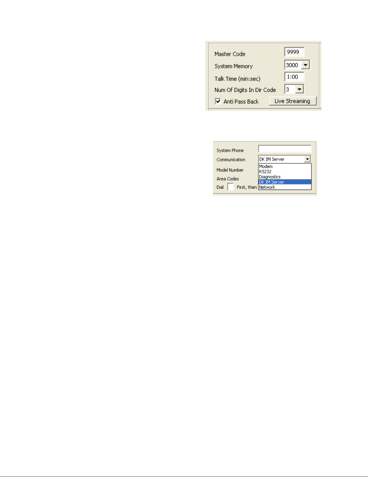
3.1.1 Entry Panel Setup (Fig 10)
1. Enter the four-digit MASTER CODE in the field
provided. The master code entered here must
match the four-digit master code that has been
programmed into the entry panel.
2. Select the SYSTEM MEMORY. The system
memory must match the memory size of the
chips installed in the entry panel.
3. Set the system TALK TIME.
4. Set the DIRECTORY CODE DIGITS.
5. Check ANTI-PASS BACK for 1833, 1835, 1837 and
1838 (APB is standard in these systems). Uncheck this box if you are programming an 1834 (APB is unavailable in the 1834).
Figure 10
3.1.2 Communication Setup (Fig 11)
1. Select Modem, RS-232, DK IM Server or Network1
from the pull-down menu (The diagnostics option is
used only when you are talking with a DKS
technician on the telephone).
Note 1: Requires installation of TCP/IP kit on the
system (P/N 1830-175).
2. If Modem or DK IM Server was selected, enter the
SYSTEM PHONE number in the field provided.
Include the area code if 10-digit dialing is required in your area. W hen using the DK IM Server,
you MUST include 1+Area Code+ Phone Number.
3. If Network was selected, you will need to enter the static, dynamic or l ocal IP address and the port
number (separated by a colon) in the System IP Address field.
Example: hostname.dyndns.org:1040
Examp
4. Select either the 1834 model, or the 1833, 1835, 1837, 1838 models.
5. Select either 10 or 255 Area Codes. The number of area codes selected here must match how
6. If the entry system is set-up on a PBX or KSU and it needs to dial a “9” to get a dia l-tone, enter the
le: 192.168.1.40:1040
the entry panel area code option was programmed; either 10 a rea codes or 255 area codes.
255 area codes are only available on REV E or higher circuit boards.
number where indicated.
Figure 11
3.1.3 Tone Open Numbers (Fig 12)
Tone open numbers are the numbers that the entry panel will respond to and will cause the programmed rel ay
action that the tone number was set for. Tone open numbers can be set to activate a single relay or any
combination of relays. Each relay has four tone open number fields that can be set, however when a call is made
to a resident, the resident can only momentarily activate the rela y - the system will not respond to other tone
open numbers from a resident.
The other three tone open number fields (Hold, Release, Hold 1 Hr.) are functions designed for the system
administrator and will cause the relay(s) in the entry panel to respo nd to the programmed command. To use
these functions, the system administrator calls the entry panel via a touch-tone telep hone, and then enters a
series of numbers to cause the desired relay action (Refer to the O wner's Manual that came with the entry panel
for instructions on using this feature).
NOTE: The 1834 and 1838 Entry Panels do not have RELAY 0 capability. Leave all Relay 0 fields blank if
programming an 1834 or 1838 entry panel.
1835-066-N-7-13 Page 25
1833, 1835, 1837 ENTRY PANELS
If Tracker™ expansion boards are used with the 1833, 1835 or 1837 entr y panels, set the tone open number(s),
postal switch and rotary dial 9 inputs to activate RE LAY 0. Relay 1 and Relay 2 are used as Tracker™ boar d
command relays in this configuration.
1838 ENTRY PANELS
Generally, tone open numbers do not need to be set when using the 1838 entry panel be cause this panel is not
designed for any voice communication requirements. However, it may be desirable to program tone open
numbers for Relays 1 and 2 (there is no Relay 0 in the 1838, leave these fields blank) so that the system
administrator can unlock doors (or open gates) under abnormal situations. For example, if a tone number is
entered in the HOLD and RELEASE fields for Relays 1 and 2, a system administrator could use this function to
command ALL doors and gates connected to the system to unlock (or open) in an emergenc y situation by calling
the 1838 from a touch-tone telephone and entering the hold open tone command. T his function requires that a
CO telephone line be connected to the 183 8 s ystem for comm unication. T his function is not availabl e if R S232 is
the only means of communicating with the 1838 system.
Figure 12
1.
Enter the tone open number for each relay under the desired function for that rela y. If a function is
not desired, leave it blank.
2. Select which relay(s) will activate when the postal switch is activated and when the entry panel
detects a rotary dial 9.
3.1.4 ENTRY CODES
Do not confuse four-digit ENTRY CODES with five-digit PIN codes. An ENTRY CODE is a four-digit number
assigned to an individual and is entered in the entry code field on the resident information screen. Ent ry codes
will activate the relay on the entry panel control board t hat it is programm ed for when the code is entered o n the
entry panel keypad only. PIN (Personne l Identification Number) CODES are five-digit c odes that are assigne d to
an individual and are entered in the device code field on t he resident information screen. T he relay that the PIN
code will activate is determined by which wiegand input the PIN keypad is connected to and security level
programming.
1. If entry codes are used, lower and upper ranges can be programmed which will cause the entry
code to activate the desired relay(s). NOTE: Entry code ranges may ov erlap allowing one entry
code to activate any combination of relays.
2. Enter the lower and upper boundary four digit entry code number for each relay.
Page 26 1835-066-N-7-13

3.1.5 Miscellaneous Setup Items (Fig 13)
1. Click the TRANSACTIONS button if transactions are to be stored in the entry system panel. The
panel can store a maximum of 8000 events in the transaction buffer.
2. Click the INTERFACE WITH 1816/1820 button onl y if the entry panel is connected to a DoorKing
Model 1816 or 1820 Telephone Intercom System.
3. Click the TRACKER button if Tracker™ expansion boards are connected to the entry panel
wiegand input(s). Note: Tracker is not available with the Model 1834.
4. Click the MULTIPLE SYSTEMS button if more than one system will be sharing the resident
database.
5. Set the DIAL TYPE to TONE for most installations. Use the rotary dial type only if the phone line
connected to the entry panel is a rotary dial phone line. NOTE: Typically, this is always set to
TONE.
6. The INFO DIRECTORY field identifies the file name that the resident information will be stored
under for the current account. This field cannot be changed and is sho wn for information purposes
only.
7. The OTHER INFO DIRECTORY field identifies the resident file name of the primary account. The
information in this field will be the same as the resident info directory field, unless this account is
sharing the resident database with another account. This field cannot be chan ged and is sho wn for
information purposes only.
8. If communicating via RS-232 or using Live Transactions, select com port 1, 2, 3, 4, and select the
speed (9600 or 19200).
Figure 13
3.1.6 System Message (Fig 14)
This section applies to the 1834, 1835 and 1 837 entry panels only. Ski p this section if you are programming the
1833 or 1838 entry panel.
1. Click the SYS MESSAGE icon in the tool bar. The Message and Instructions window will appear.
2. Click either single line (for the 1834, 1835) or 8-line (for the 1837).
3. Enter the d esired messages. The System Message has a maximum of 48 characters, while the
Instruction Message has a maximum of 54 characters. Spaces count as a character.
Figure 14
1835-066-N-7-13 Page 27

3.2 Relay Numbering and Control
The model 1833, 1835 and 1837 telephone entr y systems each have three relays (Relay 0, 1, and 2) on the
control board while the 1834 and 1838 systems eac h have two (Relay 1, 2) rela ys. When Tracker™ boards are
added to the system, the output relay on the Tracker™ boards are listed in the soft ware sequentially, beginning
with relay 3 (Relays 0, 1 and 2 are on the main control board). Tracker boards cannot be added to the 1834
system.
When Tracker™ boards are used to expand the access c ontrol system, relays 1 and 2 are used as Tracker™
Command (Cmd) relays with Relay 2 commanding Tracker™ boards 1-8 (system relays 3-10) and Relay 1
commanding Tracker™ boards 9-16 (system relays 11-18). Refer to Figure 19.
1833, 1835 and 1837 SYSTEMS ONLY
If both Relay 1 and Relay 2 are used to cont rol Tracker™ b oards, Relay 0 is us ed as the Primary Rela y that will
open a visitor door or gate when the resident pushes "9" on their telephone. Refer to section 3.1.3.
System Relay
Numbering Scheme
1833, 1835, 1837,
1838
Control Board
Rly 2
Rly 1
Rly 0
14
13
12
11
10
9
8
7
6
5
4
3
2
1
Wiegand Input
Command Relay 2 Output
Command Relay 1 Output
Wiegand Input
1
DOOR
Relay 3
System
2
DOOR
Relay 4
System
3
DOOR
Relay 5
System
4
DOOR
Relay 6
System
5
DOOR
Relay 7
System
6
DOOR
Relay 8
System
7
DOOR
Relay 9
System
8
DOOR
Relay 10
System
Tracker
Boards 1-8
Tracker
Boards 9-16
DOOR 9
DOOR 10
System Relay 11
DOOR 11
System Relay 12
DOOR 12
System Relay 13
DOOR 13
System Relay 14
DOOR 14
System Relay 15
DOOR 15
System Relay 16
DOOR 16
System Relay 17
System Relay 18
Visitor Door / Gate Control (1833, 1835, 1837 Only)
Figure 15
Page 28 1835-066-N-7-13

3.2.1 Labeling Relays with Tracker Disabled
Click the RELAYS button on the tool bar to bring up the relays screen. T he relay screen is where the output
relays of the telephone entry system can be labeled, where you will set the relay strike time for the relays, and
where you can enable the "Hold Open During Modeming" command.
NOTE: The "Hold Open During Modeming" command is not active if RS-232 communication is being used.
Use the following instructions if the TRACKER button (System Info Scre en) is not checked. If the TRACKER
button is checked, go to section 3.2.2.
1. From the SYSTEM INFO screen, click the RELAYS button in the tool bar. The relay information
screen will appear (fig 16).
2. Clicking the "Hold Ope n During Modeming" button activates the relay d uring the data transfer, and
then deactivates it when the data transfer is complete. This will cause your gate or door to remain
open during the data transfer. If this is not desirable, do not activate this fe ature. T he wiegand input
devices (cards, transmitters, etc.) remain operational during the data transfer. NOTE: This feature
is not active when using RS-232 communications.
3. Click in the name field, then enter a name for the relay. This is the name t hat will appear on the
transaction reports, for example: "Main Gate" or "Side Gate". The maximum characters that can be
entered in this field is 12 (Fig 17).
4. Click the time field and enter the time in seconds that the relay is to be activated.
5. When complete with this screen, click OK to return to the System Info screen.
6. Click the RESET button to change the relay options to the default settings.
7. Clicking the CANCEL button will reset this screen to the previous settings and return yo u to the
System Info screen.
NOTE: Relay 0 is not used with the 1834 or 1838 system. Leave this field blank if the account that you are
programming is one of these units.
Figure 16
1835-066-N-7-13 Page 29
Figure 17

3.2.2 Labeling Relays with Tracker Enabled
Click the RELAYS button on the tool bar to bring up the relays screen. T he relay screen is where the output
relays of the telephone entry system can be labeled, where you will set the relay strike time for the command
relays, and where you can enable the "Hold Open During Modeming" command.
NOTE: The "Hold Open During Modeming" command is not active if RS-232 communication is being used.
Use the following instructions if the TRACKER button (System Info Screen) is checked. If the TRACKER opti on
is not checked, refer to section 3.2.1.
1. From the SYSTEM INFO screen, click the RELAYS button on the tool bar.
2. Click "Additional Relays For Tracker 2" button to enable system relays 3-10 (Fig 18).
3. Click "Additional Relays For Tracker 1" button to enable system relays 11-18 (Fig 19).
4. Click "Hold Open During Modeming" (not active if RS-232 communication is used) to activate the
respective relays during the data transfer. This will activate ALL respective tracker board relays
during modeming, which will unlock all door s (gates) during this process. If this is not desirable, do
not turn this feature on. HINT: All wiegand input devices (cards, transmitters, etc.) remain
operational during the data transfer.
5. Click in the name field, then ent er a name for each relay. This is the name that will appear on the
transaction reports, for example: "Main Gate" or "Rear Gate". The maximum characters that can b e
entered in this field is 12.
6. The default relay strike time for system relays 1 and 2 (labeled Cmd 11-18 and Cmd 3-10) is 00
seconds. The individual relay strike times are set at the Tracker™ boards.
7. When complete with this screen, click the OK button to save the changes made and to re turn to the
System Info screen. To return to the System Info screen without saving any changes, click the
CANCEL button.
8. Click the RESET button to change the relay options to the default settings.
NOTE: Relay 0 is not used with the 1834 or 1838 system. Leave this field blank if the account that you are
programming is one of these units.
Figure 18
Page 30 1835-066-N-7-13
Figure 19

3.3 Relay Hold Open Time Zone Programming
Up to seven (7) relay hold time zones can be created in the software. The eighth time zone is labeled HOL and is
used with the Holiday Schedule. After the time zones have been created, they can then be applied as n eeded to
the system relay(s) that you chose.
NOTE: The time zones applied to the Tracker™ board relays (system relays 3-18) are only accurate to 5
minutes.
3.3.1 Creating Relay Hold Time Zones
Click the HOLD OPEN button on the tool bar to bring up the Relay Hold Open Times screen (Fig 20).
1. Enter a Begin Time and an End Time for the first time zone.
2. Click the day(s) of the week that the time zone is to be active (a check will appear in the box).
3. Repeat the above to create up to seven additional time zones. NOTE: Time Zones may
overlap.
4. Click CANCEL to return to the System Info screen without saving the time zones, or click the
CLEAR button to reset the table and start over.
5. Go to Section 3.3.2 to apply the time zones to the desired system relays, or click OK to save
the time zones and return to the System Info screen without applying the time zones to an y
relay.
Figure 20
1835-066-N-7-13 Page 31

3.3.2 Applying Relay Hold Time Zones
Once the required time zones are created, you can then apply them to the system relay(s) that you want to
operate under the time zone.
1. Click the rela y(s) next to the time zone that you want to apply the time zone to. A check will
appear in the box (Fig 21).
2. Use the scroll button under the relay number table to access system relays 11-18.
3. Click OK to save the time zones and return to the System Info screen.
4. Click CANCEL to return to the System Info screen without saving any changes.
5. Click CLEAR to clear all time zones.
In the example below, four time zones have been created. Referring back to Figure 19 on page 25, Relay 3 has
been labeled Res Veh Gate (Resident Vehicle Gate). Time zones 1 and 2 have been a pplied to Relay 3, which
means that on Monday through Friday, the resident vehicular gate will automatically op en at 6:00 AM a nd remai n
open until 8:00 PM. On Saturday and Sunday, this gate will open at 8:00 AM and remain open until 8:00 PM.
Again refereeing back to Figure 19 on page 25, Relay 5 has been labeled Office. Time zone 3 has been applied
to Relay 5, which means that the office door will unlock at 9:00 AM and re main unlocked until 5:00 PM Monday
through Friday. This door will remain locked on the weekends.
Relay 9 is labeled the Serv Ent (Service Entrance). Time zone 4 has bee n created and applied to this entry only
(relay 9) meaning that this door will open at 7:00 Am and relock at 5:0 0 PM Monday through Friday, and will
remain locked on the weekends.
Figure 21
Page 32 1835-066-N-7-13

3.4 Holiday Schedules
You can create up to 32 holidays in the HOLIDAY SCHEDULE window. When a holiday date is not pr esent, the
holiday hold open times are not in effect. When a holiday date is present, the holida y hold open times are in
effect.
You can apply the holiday schedule to Securit y Levels by checking the HOLIDAYS FOR SECURITY LEVELS
button in the Holiday Schedule window. Doing this establishes Time Zone 4 (T Z4) in securit y levels 2 th rough 31
as a Holiday (HOL) time zone. Note: Does not apply to Model 1834.
CAUTION: If you turn on Holidays for Security Levels by placing an “X” in the box, the HOL Time Zone
will supersede all other time zones established within the security level. If you have more than a single
time zone programmed within a security level, this will cause all the time zones to revert to the single
HOL time zone that you establish.
Click the HOLIDAY button on the tool bar from
1.
the relays window to display the holiday
schedule window (Fig 22).
2. Enter the holiday name, month and day.
Clicking the down arrow will display a calendar
(Fig 23).
3. Click CANCEL to return to the System Info
screen without saving any changes.
4. Click CLEAR to clear all holidays.
5. Click OK to save the holidays that you created
and to return to the System Information screen.
Some holidays will need to be updated on a yearly
basis. For example, Memorial Day, Labor Day and
Thanksgiving Day usually fall on different days of the
month each year. These holidays will have to be
updated year to year.
Figure 22
Figure 23
1835-066-N-7-13 Page 33

3.5 Security Levels
Security Levels (SL) allow you to control indiv idual access t hroug h the controlle d entr y poin ts by persons using a
wiegand device (card, transmitter, PIN, etc.). As an example of this, a plant manag er may have 24 hour, seven
day a week access into the plant, but individual workers will only be granted access depending on which shift
that they work. It is also possible to allow a person 24 hour a day access at one e ntry poi nt, but limit their access
at another entry point. This is possible because each security level can have up to four different time zones
created. Note: Security levels do not apply to Model 1834.
Individuals can only be assigned a single security level (see sect 4), however there are 31 different security
levels available. The first two security levels are factory set and cannot be changed. SL00 disables all devices
(cards, transmitters, etc.) assigned to an individual. An example of using SL00 would be for an individual who
has been evicted from an apartment, or an employee who has been fired from a job, and the y are no longer
granted access at any entry point. In effect, SL00 "turns off" all devices assigned to that individual. The opposite
of SL00 is SL01, which enables all devices assigned to an in dividual o n a 24 hour a day, 7 day a week basis. A n
example of using SL01 would be for management or mai ntenanc e personnel who need access at all entry points
at all times.
The remaining 29 Security Levels (SL02 - SL30) can eac h have up to four (4) Time Zones (TZ) created within
them allowing up to 116 different time zone combinations. If the Holidays Schedule for Securit y Levels button
was checked in the Holiday Schedule window, then Time Zone 4 (TZ4) becomes the Holiday time zone and will
show as HOL on the screen. CAUTION: The HOL time zone overrides all oth er time zones within the security
level.
Anti-Pass Back – If anti-pass back is in use, residents with security levels 02 through 27 will be limited b y APB as
well as the usual time, day and relay limitations set up in the security level assigned to them. Security levels 01,
28, 29 and 30 are not limited by APB.
Leave the FLOORS buttons (1-64) blank when elevator control is n ot being used. If elevator control is in use,
refer to Section 3.8 for additional programming information.
Figure 24
Page 34 1835-066-N-7-13

3.5.1 Planning Security Levels
Refer to figures 25 – 31
Successful use of security levels (SL) begins with determining who the system users are going to be and what
access control restrictions will be placed on them. Keep in mind th at only one security level can be assigne d to
an individual user of the system, therefore the security level created for them must address all of the users
access needs. The example below gives you an idea of some of the things to consider as you plan your securit y
levels and access control requirements. The hypothetical access system described below controls access to the
following; separate visitor and resident vehicular gates, a resident pedest rian gate, a service entrance vehicular
gate, a South entrance vehicular gate, a pool gate, a laundry room, an exercise room and the management
office. Elevator control is not in use with this hypothetical access system (see section 3.7 for elevator control).
Refer to the instructions and diagrams in Section 3.5.2 for instructions on how the Security Levels de scribed
below were created.
In a typical gated community or apartment building, residents must have a security level t hat allows them access
to their homes 24 hours a day, 7 days a week, but restricts them from gaining access to areas that are closed at
certain times of the day - the office or pool for i nstance. In this case, we cannot use SL01 because this securit y
level allows access 24 hours a day at all controlled access points.
The answer to this problem is to create a security level (start with SL02) with time zone 1 (TZ1) set for 24 ho ur a
day, 7 day a week access (Fig 25). You then apply this first time zone to the relays that control the main entry
gate or main entry door (relay 3), any pedestrian gates (relay 4), rear entrances (relay 11), etc. Once you have
created the first time zone (TZ1) within the first security level (SL02) and applied this T Z to the re lays that control
the access points where 24 hour a day, 7 day a week access is to be granted, you can then use the next thre e
time zones (TZ2, TZ3, TZ4) within the security level (SL02) to restrict the users access to other access points.
Let's next consider access to the pool, laundry and exercise room areas. Time zone 2 (TZ2) is set to allow
access from 8:00 AM to 10:00 PM seven days a week (Fig 26). This time zone is then applied to the relays
(relays 6, 7, 8) that control access to the pool, laundry an d exercise room areas. The next ar ea is access to the
management office. TZ3 is set to allow access from 9:00 AM to 5:00 PM, Monday through Saturday only (the
office is closed on Sundays) and then applied to relay 5 that controls access to the office (Fig 27). You have
now created a security level (SL02) with three different tim e zones and a holiday sc hedule that will allo w entry at
all times through the main gate(s) and/or door(s), and restricts access to certain times of the da y for the pool,
laundry, and exercise room, and limits access to the offic e area to six days a week at certain times only, and
applies a holiday schedule time zone to the office and service entrances.
Next create another security level (SL03) for the landscape and pool service companies. In this example
application, these vendors are allowed access to the propert y at the service entrance Monday through Friday,
8:00 AM to 5:00 PM only (Fig 28). In SL03, TZ1 is set for these times and applied to the respective relays (relays
6, 9). Vendors are now limited in the days and times that they can gain entry to the propert y, and must use the
service entry. It is possible to create security levels for eac h vendor to restrict them to access on certain days of
the week only, and to restrict access to their respective area of concern onl y. The problem with the securit y level
created in the first part of this paragraph is that it will allow all vendors access to all areas within the time limits of
the security level. For example, the laundry service vendor needs access onl y to the laundry room, not to the
pool or exercise rooms. In this case, SL04 has been created with TZ1 set from 8:00 AM to 5:00 PM, and applied
to relays 7 and 9 which control access to the service entry gate and laundry room only (Fig 29).
Another security level (SL05) is created for the office personnel to allow them access to the office (relay 5). The
office is open from 9:00 AM to 5:00 PM, however access will be allowed to these persons from 7:00 AM to 6:00
PM Monday through Friday only (Fig 30). A second time zone (TZ2) has been created within this security level to
restrict office personnel to use the South entry only (relay 11) and to grant access to the pool, laundry and
exercise areas one hour before and after these common areas open (Fig 31).
Office managers, the resident property manager, and maintenance personnel are assigned SL01, which will
allow these users access to all entry points at all times.
When designing and creating your security levels, if the Anti-Pass Back f eature is go ing to b e used, APB
is only supported by security levels 02 through 27. System users who have anti-pass back enabled on
their access cards must be assigned a security level within this range.
1835-066-N-7-13 Page 35

3.5.2 Creating Security Levels
Using security levels requires two basic programming steps. The first step is to plan and create the individual
security level(s) required and then apply them to the indi vidual entry points (relays). Refer to the Security Level
Planning Chart in the back of this manual to see how Security Level 02 was first planned. The second step is to
assign the security level to the individual users of the s ystem. This second step is accomplished in Section 4 Data Base Management.
PROGRAMMING SECURITY LEVEL 02
1. Click the SECURITY LEVEL button to
access the security level screen.
2. Click the Security Level pull down
menu down arrow button to select
which security level you want to
create. If you are creating the first
security level, we suggest that you
start with SL02.
3. Click TZ1 to set begin and end times
for the first time zone in this security
level.
4. Click the begin time and enter the
time desired. Likewise, click the end
time and enter the end time desired.
5.
Select the days of the week for this
time zone (an X will appear in the box
when the day is selected).
6. Select the relays that you want this
security level to apply to. NOTE:
Clicking the RELAYS button will
cause the Relays screen to appear.
This is where you "named" the relays
(pg. 25). From here you can
determine which relays you want this
security level to control. Click
CANCEL to return to the Security
Level screen.
7. Click TZ2 to set up begin and end
times, days of the week, and the
relays that this time zone is to be
applied to.
Repeat step 7 to set up time zones 3
8.
(TZ3) and 4 (TZ4).
NOT
E: The FLOORS buttons are left blank
when elevator control is not used. See section
3.8 for additional programming instructions
when using elevator control.
Figure 25
Figure26
Figure 27
Page 36 1835-066-N-7-13

PROGRAMMING ADDITIONAL SECURITY
LEVELS
9. Click the Security Level pull down menu
down arrow button to select the next
security level you want to create.
10. Enter the begin and end times for TZ1,
select the days of the week for this time
zone and select the relays that this time
zone will be applied to.
11. Click TZ2 and enter the begin and end
times for TZ2, select the days of the week
for this time zone and select the relays
that this time zone will be applied to.
2. Click TZ3 and enter the begin and end
1
times for TZ3, select the days of the week
for this time zone and select the relays
that this time zone will be applied to.
1
3. Click TZ4 and enter the begin and end
times for TZ4, select the days of the week
for this time zone and select the relays
that this time zone will be applied to.
14. Repeat steps 9-13 to create additional
security levels.
To view all the security levels that have been
created, click the VIEW ACTIVE SL button. Click
the DONE button to return to the Security Level
window.
Click the CLE
AR TIME ZONE button to reset the
time zones in the current window.
Click OK to return to the SYSTEM INFO screen.
NOTE: The RELAY/ELEVATOR button is used with
elevator control only. If Elevator control is in use,
see section 3.8 for additional programming
instructions.
Figure28
Figure 29
Figure 30
Figure 31
1835-066-N-7-13 Page 37

3.6 Anti-pass Back
Anti-Pass Back (APB) is a feature that addresses the problem of a user handing his card (or other access
device) to someone else to use. This is accomplished by recording an ‘APB VIOLATION’ when a card is used at
the same reader twice in a row without being used at a different reader in between. For exampl e, lets assume
you have a secured area with both an ‘IN’ card reader and an ‘OUT’ card reader. If card #12345 is pr esented at
the ‘IN’ reader two times in a row without being used at the ‘OUT’ reader, an APB violation has occurred.
NOTE: Users must be assigned a security level of 02 through 27 for the APB feature to be active.
3.6.1 True Anti-pass Back
The APB function in the DoorKing software is TRUE anti-pass back and can be s et up to operate in one of three
different modes.
PASSIVE APB – will record an APB VIOLATION in the transaction buffer if a card is presented two or
more times in a row at the same reader. Access (or exit) will be granted.
ACTIVE APB – will record an APB VIOLATION in the transaction buffer if a card is presented two or
more times in a row at the same reader. Access (or exit) will be denied.
TRAP APB – will trap the ‘user’ in the facility with an illegal use of the card and will record an APB
VIOLATION in the transaction buffer. Active and trap are different in that with ACTIVE APB, the card
will not work at either the IN or OUT card reader once an APB violation has occurre d. With TRAP APB,
once an APB violation has occurred, the card will work at the IN card reader but will not work at the
OUT card reader since it was used twice in a row at the IN reader. This card is TRAPPED in the facility.
3.6.2 Facility Counter
The APB feature also uses a FACILITY COUNTER that keeps a running total of the number of users in the
facility. The information can be used to determine, for example, what percentage of a par king facilit y is in use at
a given time. The counter can be set to OFF, record ever y 15 MINUTES, record ever y 30 MINUTES, or record
EVERY HOUR. When a transaction upload is completed, a ‘USERS IN FACILITY’ report can be run to see ho w
many users were in the facility at the intervals selected. When the APB feature is first put into use, the facility
counter can be manually set with the number of vehicles (people) currently in the facilit y so that you have an
accurate count as the APB features begins to operate.
3.6.3 Re-sync operations
When the APB feature is first enabled, all cards will have 1 RE-SYNC move set. This is also true for new cards
added to the system. That is, whether the card is currently IN or OUT of the facility does not matter. The system
will allow them one ‘move’ and then start looking for APB violations. You can at any time RE-SYNC ALL
DEVICES, RE-SYNC FROM A LIST OF DEVICES or SCHEDULE RE-SYNC’s.
For example, if APB was in use in a parking garage with a barrier arm and the arm is broken, people will
naturally just drive out without using their card to open the gate for exit. Kno wing that a number of people drove
out without using their card, you can do a manu al re-s ync so that you won’t have several APB violatio ns the ne xt
morning.
The program will also allow you to sche dule a re-sync of all cards on a regular basis. It might be a situation
where APB is only enforced say from 8 AM to 6 PM. Entries are un-regulated and vehicles are allowed free
entry after 6 PM. You can schedule a re-sync for 2 AM (when the lot is empty) so that persons who l eft after 6
PM will not have an APB violation the next morning.
Page 38 1835-066-N-7-13

3.6.4 Programming Anti-pass Back
1. Click Anti-Pass under the System Information folder in the sidebar or click the Anti-Pass button i n
the tool bar. The Anti-Pass Back window will appear.
2. Select PASSIVE, ACTIVE or TRAP anti-pass back mode from the pull-down menu.
3. If the counter is going to be used, select the time interval from the pull- do wn menu, othe r wise leav e
the selection to OFF.
4. Select which relays are to be designated as IN, and which relays are to be designated as OUT.
You can click the RELAY button that will bring up the relay screen that was programmed in 3.2.1
and 3.2.2 to show how each of your relays are currently labeled.
5. One Time Functions – Se lecting Re-Sync All Devices will cause all devices to be re-synced at the
next download. Selecting Enable Re-Sync List will cause only the card number(s) entered in the
list to be re-synced at the next download. Up to five (5) card numbers can be entered on this list.
6. Check the Reset Facility Counter button and enter the number of cards currently in the facilit y. If
the facility counter is not used, leave this blank.
7. Click the Enable Scheduled Re-Sync All button to enable the re-sync schedule. The system will
automatically re-sync all card codes at the time and dates specified in the schedule.
8. Click OK to save the Anti-Pass Back setup and return to the SYSTEM INFORMATION window.
Figure 32
1835-066-N-7-13 Page 39

3.7 Facility Codes and Device Association
The software allows for the option of using or not using device facility codes. When the facility code functio n is
enabled, the device facility code must match with a facilit y code entered in the program, other wise access will be
denied. If you do not want to use facility codes, leave the facility code enable button unchecked.
3.7.1 Facility Codes
1. Click the FACILITY CODE button on the tool bar. The
Facility Code window will appear (fig 33).
2. To enable facility codes, click the ENABLE FACILITY
CODE button. Note: you must check this box to enter
facility codes.
3. Enter up to 10 3-digit facility codes. Note: valid facility
codes are 000 – 255.
4. Click CANCEL to return to the system info screen
without saving these changes.
5. Click CLEAR to reset the fields.
6. Click OK to save the changes.
When using DKS MicroPLUS transmitters, leave the first 0 in the
4-digit facility code off so that you enter only a 3-digit number.
For example, if the facility code is 0124, enter 124 in the f acility
code field.
Figure33
Page 40 1835-066-N-7-13

3.7.2 Device Association
The DEVICE ASSOCIATION function allows you to associate the names of a card, transmitter, or other 26-bit
wiegand devices connected to the system with certain code numb ers restricted to that device. For example, if an
entry system is using a combination of card readers and RF transmitters, this feature allows you to name a range
of codes associated with each device. This function will also allow you to "mass enable" (turn on) a specified
range of codes at one time.
NOTE: Device association simply associates a range of "device" codes with a device name that you create.
1. From the SYSTEM INFO screen, click the
DEVICE ENABLE button on the tool bar. The
default Device Association window will appear
(Fig 34).
2.
Click the "Device Name" field and enter a
name for the device (12 characters max).
3. Click the "From" field and enter the beginning
device number. Click the "To" field and enter
the ending device number.
4. Repeat steps 2 and 3 to enter additional device
names and ranges (Fig 35).
5. Click the OK button (or press ENTER) when
complete or click the "Mass Enable" arrow next
to the device codes that you want to activate
(see 3.7.3).
In the example, a combination of access cards,
MicroPLUS™ transmitters, and personal identification
numbers (PINs) have been used for access control
purposes. Device names are a maximum of 12
characters. In this example, access cards have been
labeled "Cards", MicroPLUS™ transmitters have been
labeled "Trans", and PIN codes have been labeled
"PIN". Notice also that three different sets of cards have
been issued, each with their own unique range of codes.
The labels "Cards," "Trans" and "PIN" will be used in the
transaction log anytime a device within the respective
ranges is used. In addition, the first letter of the device
name will show on the resident screen under the T
(type) field to identify the type of device.
IMPORT
a range of device codes. To activate (turn on) these devices, go to section 3.7.3. De vice codes must be
entered as a 5-digit number betw een 00001 and 65407. The system allows a maximum of 8000 device
codes, therefore you simply cannot "mass enable" codes 00001 through 65407 as this exceeds the
maximum amount of device codes allowed.
ANT: These steps do not activate (or turn on) any de vice co des. Device association only "labels"
Figure 34
Figure 35
1835-066-N-7-13 Page 41

3.7.3 Mass Enable
The MASS ENABLE function allows you to activate (turn on) a range of device codes at one time. This allows
resident managers or access system administrators to activate a group of cards (or transmitters or PINs) prior to
the devices being issued or any users being entered in the database. Once the user(s) is entered in the
database, the manager can select the card (or transmitter, or PIN) and as sign it to the user. See section 4.2 for
programming instructions on assigning "mass enabled" codes to system users.
1. Click the ARROW to the right of the device
that you want to mass enable. The Mass
Enable window pops up.
2.
Enter the range of codes that you want to
mass enable and enter a Security Level
for this range if desired (fig. 36). NOTE:
Entering the security level is optional. If
the security level is left blank, the software
will automatically assign security level 01
to the device codes. Keep in mind that
when you assign (see 4.2) a device code
to a user in the database, the security
level will automatically change to that of
the security level assigned to the user.
3. Click the SORT button. The codes will now
be turned on and the range that you
entered in step 3 will move to the field
below (Fig. 37).
4. Repeat steps 2 through 4 to mass enable
other device codes.
To reverse this process, select the device
5.
codes that have been mass enabled by
clicking on them, then click EDIT to
change the devices codes that are mass
enabled or click DELETE to deactivate the
device codes that have been mass
enabled.
6. Click the CLOSE button to close the mass
enable window.
In the example in figure 36, device codes 01000
through 01999 have all been "Mass Enabled" and
placed in security level 2 (SL02). From the device
association window (fig. 35) we know that these
device codes represent access cards.
Once the
device codes have been mass enabled,
they are active (turned on) and ready to be
"assigned" to a system user. Refer to section 4.2 for
instructions on assigning device codes to the
system users.
Figure 36
Figure 37
Page 42 1835-066-N-7-13

3.8 Elevator Control
The elevator control feature is typically used in high-rise a partment buildings or office buildings and is designed
to limit which elevator(s) and which floor(s) a person is allowed access to. This control c an be applied t o building
residents and to visitors that have been granted access by a resi dent. In its most common use, when a resident
grants access to a visitor, the system will call the designated elevator(s) to the gr ound floor, and then only the
floor button that the resident resides on will be active in the elevator(s). This prevents the visitor from a ccessing
other than the designated elevator(s), or from going to unauthorized floors. Elevator re strictions for visitors are
programmed in Section 4.1.1.
Elevator control can also be applied to residents to control which elevator( s) they can use and to which floor(s)
they are allowed access. In this application, a card reader is installed inside the elevator(s) car. When the
resident enters the elevator, they must use their access card to "turn on" the elevator buttons. The buttons that
will be turned on are set in the software. Security levels can also be applied to elevator control, however the
SL01 security level does not affect elevator control and will not grant unrestricted access to all floors in a buil ding
that uses elevator control. Therefore, if it is necessary to allow certain personnel unrestricted access to the
elevators and floor numbers, a security level should be created for this requirement (see SL06, page 41).
Elevator restrictions for system users are programmed in sections 3.8.3.
NOTE: Elevator control requires the installation of the 2348 Elevator Control board(s). This software and
hardware will control a maximum of eight (8) elevators with each elevator serving up to 64 floors.
3.8.1 PLANNING ELEVATOR CONTROL / SECURITY LEVELS
Refer to the instructions and diagrams in Section 3.8.3 for instructions on how Security Levels and Elevator
Control has been used to meet the criteria in the following hypothetical building.
The following example assumes that access control is used in a high-rise apartme nt building with four elevators.
Floors 2 through 4 in this building are reserved for private business. On the 20th floor of this building is a
exercise room that is open from 6:00 AM to 11:00 PM, seven days a week, but access is restricted to only those
residents that pay a monthly fee for the use of the facility. There is a main entry door where the private business
employees, building residents and guests have access. System users (building residents and business
employees) use a card to gain access to the building while visitors will use a telephone entry system to
communicate with the person they wish to visit. A rear entry door is reserved for residents and service personnel
only and access is controlled at this entry with a card reader only. Elevator control is used in this application and
each of the four elevators has a card reader installed in the elevator car.
The building residents are to be granted access 24 hours a day, seven days a week at the main and rear entry.
They will be allowed to use any of the four elevators, but will not have elevator access to the business floors (2,
3, 4). The exercise room in this building is open to residents seven days a week, but the hours are restrict ed from
6:00 AM to 11:00 PM., and only those residents that hav e paid a monthly user fee will be gr anted access to this
area. Visitors will only be allowed access to the floor that th e person they are v isiting lives on, or to the floor that
the office they are visiting is located on, and they (visitors) can only use elevators 1 or 2. The business
employees are granted access only at the main entr y door, Monday through Saturd ay from 6:00 AM to 8:00 PM.
These business employees are restricted to floors 2, 3 and 4 using elevators 1 and 2 only. The business
managers are granted access 24 hours a day, seven days a week, but are restricted to floors 2, 3 and 4 onl y via
elevators 1 and 2 only. Building maintenance personnel and management personnel are granted access 24
hours a day, seven days a week at all controlled entry points and ca n use any of the four elevators and are not
restricted to any floors.
1835-066-N-7-13 Page 43

IDENTIFY THE SYSTEM RELAYS
T
he first step is to identify the system relays
that will be used and to name them (refer to
3.2.2). System relay 1 will be used to control
the main entry door and is labeled "Main
Entry." System relay 2 becomes the command
relay for the Tracker™ expansion boards used
in this application and is labeled Cmd 3-10.
System relay 3 is the card reader on the rear
entry and is labeled "Rear Entry." System relay
4 is the card reader that allows access to the
exercise room (Exercise Rm) and system
relays 5, 6, 7 and 8 are the card readers
installed in elevators 1 through 4 respectively
(Fig. 38).
Figure 38
3.8.2 Programming the Relay/Elevator Control Table
Programming elevator control for the system users (the building residents and busines s employees) consist of
two steps (elevator control for visitors is programmed in Section 4.1.1). The first step is to program the Relay /
Elevator Table. This table tells the access system which system relay controls which elevator and sends this
information to the elevator control board. As identified in figure 41, system relay 5 is activated by the card reader
in elevator 1, system relay 6 by the card reader in elevator 2 , system relay 7 by the card reader in elevator 3, and
system relay 8 by the card reader in elevator 4.
The second step will be to program the appropriate securit y levels needed to control access as descri bed in our
hypothetical application. Besides restricting access to certain days and times and certain access locations, these
security levels will also restrict users to certain floors and determine which elevators they can use.
PROGRAMMING THE RELAY / ELEVATOR TABLE
Click the RELAY / ELEVATOR button on the
1.
tool bar. The Relay / Elevator Table window
will appear.
2. T he system relay numbers are listed on the left
side of the table. Use the scroll button to scroll
up or down to view all the system relay
numbers. The elevator numbers (1-8) are listed
across the top of the table.
3. Click the box under the elevator number that
the corresponding system relay is to control. In
this example, elevator 1 is controlled by system
relay 5, elevator 2 by relay 6, elevator 3 b rela y
7, and elevator 4 by relay 8 (Fig. 39).
4. Click OK to set the table, click CLEAR to start
over, or click CANCEL to return to the system
info screen without saving any changes to the
Relay / Elevator Table.
Figure 39
Page 44 1835-066-N-7-13

3.8.3 Programming Security Levels with Elevator Control
The first step is to identify the different security levels required to control access as described in our hyp othetical
building, and then to program these levels into the s oftware program. Refer to Section 3.5 for more information
on programming security levels.
SL02
his security level is created to allow
T
building residents 24 hour a day, seven
days a week access into the building (TZ1)
either through the main entry (relay 1) or
the rear entry (relay 3). It also allows them
to use elevators 1, 2, 3 or 4 at any time
(relays 5, 6, 7 and 8), and allows them to
access floors 5 through 19 (note that floors
5-19 are activated). Floor 20 is not
included in TZ1 because access to the
exercise room (relay 4) is not available 24
hours a day (Fig 40). TZ2 is created to
allow residents with exercise room
privileges access to the exercise room
(relay 4) and allows them to gain access to
the 20th floor by any of the elevators
during the times defined by TZ2 (Fig 41).
SL03
Z1 is identical to SL02-TZ1, but
SL03-T
SL03 does not have any other additional
time zones. This security level was
created to allow residents without exercise
room privileges access to the building and
all floors with the exception of the exercise
room and floor 20 (Fig 42).
NOTE: You cannot simply assign SL02 to
the residents who do not have exercise
room privileges, even though SL02-TZ1 is
identical to the SL03 security level.
Remember, SL02-TZ2 allows access to
this restricted area. Assigning SL02 to
these residents will give them access to
this area!
he two security levels created here meet
T
all the access control requirements and
restrictions for the building residents as
described in 3.8.1. Additional security
levels now need to be created to meet the
access control and access restriction
requirements for the businesses located
on floors 2, 3 and 4.
Figure 40
Figure 41
Figure 42
1835-066-N-7-13 Page 45

SL04
T
his security level will be assigned to the
employees who work at the businesses
located on floors 2, 3 and 4. Access is
limited to the main entry only (relay 1)
Monday through Saturday, 6:00 AM to
8:00 PM. This security level allows the use
of elevators 1 and 2 only, and restricts
access to floors 2, 3 and 4 only (Fig 43).
SL05
allows business managers access to
SL05
their offices 24 hours a day, seven days a
week through the main entry only. Access
is restricted to the main entry, and the
managers can only use elevators 1 or 2
(Fig 44).
SL06
he other criteria defined in our
T
hypothetical building was that the building
owners and maintenance personnel are t o
be allowed access 24 hours a day, seven
days a week at any entrance, and are
permitted to use any of the elevators.
Since SL01 does not address the elevator
control boards, SL06 is created to allow
access to these persons under the
conditions stated (Fig 45).
Figure 43
Figure 44
Figure 45
Page 46 1835-066-N-7-13

VISITOR FLOOR CONTROL
The next access control criteria to meet in this application is to restrict access for visitors. When a visitor is
granted access to the building, they will be allowed access o nly to the floor that the person they are visiting
resides on. Further restrictions can limit the visitor as to which elevator(s ) they may use. For example, assume
Mr. Smith is visiting Mr. Jones who lives on the 10th floor of our building. When Mr. Jones grants acc ess to Mr.
Smith by pressing 9 on his telephone, the s ystem will "turn on" only the 10th floor button in the el evator(s). Mr.
Smith will not have access to any other floor.
This floor control programming is set in the data base management section. For information on programming this
elevator floor control for visitors, see Section 4.1.1.
1835-066-N-7-13 Page 47

SL02
Assigned to residents with exercise room privileges.
TZ1
in this security level provides access 24 hours a day,
7 days a week through the main and rear entry doors,
and allows them to use any of the four elevators to access
floors 5 through 19.
TZ2
in this security level allows these residents access to
the exercise room and access to floor 20 via any of the
elevators from 6:00 AM to 11:00 PM, 7 days a week.
SL03
Assigned to residents without exercise room privileges.
TZ1
in this security level provides access 24 hours a day,
7 days a week through the main and rear entry doors,
and allows them to use any of the four elevators to access
floors 5 through 19 only.
Exercise Room. Access to
Floor
20
residents with SL02 only,
and personnel with SL06.
SL04
Assigned to private business employees.
TZ1
in this security level provides access Monday through
Saturday, 6:00 AM to 8:00 PM through the main entry door
only, and restricts them to elevators 1 and 2 to access floors
2, 3 and 4 only.
SL05
Assigned to private business managers.
TZ1
in this security level provides access 24 hours a day,
7 days a week through the main entry door only, and restricts
them to elevators 1 and 2 to access floors 2, 3 and 4 only.
SL06
Assigned to building owners, maintenance personnel.
TZ1
in this security level provides access 24 hours a day,
7 days a week at all entry locations with no elevator or floor
restrictions.
Floors
5 through 19
Floors
2 through 4
First Floor
All Residents with SL02 or SL03
24 Hours, 7 Days a Week
Private Business Personnel with SL04
Monday - Saturday 6:00 AM - 8:00 PM
For Guest
Telephone Entry
Residents and
Private Business
Elevator 1 Elevator 2 Elevator 3 Elevator 4Main Entry Rear Entry
Visitors and
Private Business
Exercise Room Access 6:00 AM - 11:00 PM,
Residents with SL02
7 Days a Week
Business Managers with SL05
24 Hours, 7 Days a Week
Residents and
Personnel with SL06
Personnel with SL06
24 Hours a day, 7 days a week
Resident and
Service Entry
Page 48 1835-066-N-7-13

1835-066-N-7-13 Page 49

SECTION 4 – DATABASE MANAGMENT
Once the account(s) has been created (chapter 2) and the system operating parameters have been set (chapter
3), the access control system user database must be programmed. This information includes entering al l the
users (residents) names, phone numbers, assigning directory codes, assigni ng four digit entry codes if used,
assigning a security level to the user, assigning a device code(s) (card, transmitter or PIN) to the user, and
setting floor restrictions for visitors if elevator control is in use.
The control board series that was chosen when you first created an account (Chapter 2) will affect how the user
database is programmed. This chapter and the illustrations in it address p rogramming an entry panel with a 30
Series control board. If you created an account with a 40 Series Enhanced, 40 Series or 50 Series control
board, refer to the User Manual Version 5.6 for programming instructions.
4.1 User (Resident) Information
1. In the sidebar, click the + sign on the account that you are going to input the user data for.
2. Click RESIDENTS.
3. The User (Resident) information screen will appear (Fig 46).
4. The factory default for the name field is “RESIDENT .” This can be changed to any other identifi er
(12 characters maximum) that best suits your needs. Right click Resident and type in th e identifier
you prefer. For example, you may want to enter “EMPLOYEE” if the system is used in a business
environment.
Figure 46
Page 50 1835-066-N-7-13

4.1.1 Adding Database Information
1. Enter the resident (user) name in the name field.
2. Click the H (Hide) button if this name is NOT to be displayed on the electronic directory. (Not
applicable if programming is for the 1833 or 1838 system).
3. Enter a 3-digit Alternate Area Code (AAC) if 10-digit dialing is necessary, or enter a 4-digit AAC
(1+area code) for any long distance dialing requirements. The maximum AACs than can be used
with this system is 255.
4. Enter the resident phone number. (Optional if programming an 1838 system).
5. The directory code is filled automatically by the software, or you can enter your own directory code.
The directory code length (1, 2, 3 or 4 digits) was set i n Chapter 3. The di rectory code will increas e
sequentially as you add new names. NOTE: We suggest that you start with directory code 2, 02,
002 or 0002 (the number of digits is determined by the setting you chose in Chapter 3). T he reason
for this is that the first two directory codes (000 and 001, as a three digit example) have their talk
time factory set for the maximum and this setting cannot be changed. You should use these
directory codes when programming a manager’s office or an emergency number.
6. Enter a 4-d igit entry code ( optional) assigned to this user. NOTE: An entry code is an access code
that the user enters on the entry system keypad to gain access at the entry point defined by the
entry code range numbers and relays. (Entry codes are not used with the 1838 system because
this system does not have a keypad accessible by the users.) Do not confuse 4-digit entry codes
with 5-digit PINs (Personnel Identification Number). PINs are entered on a keypad that sends the
data to the system via wiegand output and treated in the system like card and transmitter codes.
7. Enter the 2-digit Security Level assigned to this user. The default SL is 01. NOTE: To view the
security levels created in Chapter 3, click the SEC. LEVEL button.
8. The T field stands for "Type". This field is automatically set by the soft wa r e wh ic h wi l l en t e r t h e fi r st
letter of the "type" of device you created in the Device Association window in Chapter 3. For
example, if device code 01000 was labeled as a "Card" in the Device Association window, a "C" will
appear in this field if this device code is assigned to a resident.
9. Enter the 5-digit device code in the Device field. NOTE: If the "Mass E nable" feature was used to
activate a range of device codes, leave this field blank. Aft er entering all of the user informati on in
the database, you can then use the ASSIGN button to assign the device codes to the users you
chose. See 4.2 for more information. Device code numbers must be between 00001 and 65407
with a maximum of 8000 codes allowed.
10. If elevator control will be used with this access system, enter the floor number in the F L field that
the resident (user) resides on.
11. Enter the Elevator Reference number in the ER field if elevator control is used. The default ER is 1.
See 4.3 for more information on setting the Elevator Reference.
12. You can enter up to 80 characters in the notes field.
13. Press ENTER to enter t he current information and create a record in the database for this user.
Click the ADD button in the tool bar or simply place the cursor in the next name field to add
additional users.
14. Vendor information is entered into the data base in the same manner as are the system users with
the exception that vendors do not have a phone number field.
15. Use the SEARCH button to search on any of the fields on the resident information screen to locate
specific information or a specific user.
16. Click the STATISTICS button to determine how many user are currently programmed into the data
base, the number of Directory Codes used, how many Mass Enabled devices are currently
programmed, etc.
Notice in the example on the next page (Fig 47) that the device codes have not yet been assigned to the
individual users. Device codes may be entered when the user information is being entered, or if the MASS
ENABLE (3.7.3) feature was used to activate a range of device codes, these devices can now be ASSIGNED to
the individual users. Refer to Section 4.2.
1835-066-N-7-13 Page 51

Figure 47
Page 52 1835-066-N-7-13

4.2 Assigning Device Codes
To use the Assign feature, device codes must be Mass Enabled (3.7.3).
1. Click the user (reside nt or vendor) that you are
going to assign a device (card, transmitter,
PIN) code to. An arrow appears next to the
user name.
Click the ASSIGN button. The Assign Device
2.
Number window will appear (Fig 48).
3. Select a device number by clicking on it.
NOTE: More than one device can be selected
by dragging the mouse pointer over the
number of device codes that are to be
assigned to the resident in step 1.
4. Click the ASSI GN button to assign the device
codes to the user.
5. Select the next user in the Resident Info
screen. Note: You do not have to close the
assign window.
6. Repeat steps 3 and 4 to assign devices t o the
other system users.
7. When complete, click the CLOSE button to
close the Assign window.
NOTE: The device that is assigned will assume the
Security Level of the user. For example, if you assign a
device code with a security level of 02 to a user who has
security level 03 assigned to him, then the device will
automatically assume security level 03 when it is
assigned to this user.
Figure 48
1835-066-N-7-13 Page 53

4.3 Elevator Reference
The Elevator Reference table is part of the elevator control feature that is typically used in high rise apartments
or office buildings and is designed to limit which elevator(s) and to which floor a visitor is allowed access to after
being admitted by a resident. To use the elevator control for visitor access, the resident must have th eir floor
number entered in the FLOOR (FL) field on the Resident Info screen. This tells the system which floor the visitor
will be allowed access to.
The Elevator Reference table sets which elevator(s) the visi tor is allowed to use and sets a time lim it as to how
long the floor button will be active after access has been granted. Up to eight (8) Elevato r References (ER) can
be programmed for greater flexibility. Typically, you will need only a single ER.
NOTE: Elevator control is only available with 30 Series and ENHANCED SERIES 40 boards and req uires the
installation of the 2348 Elevator Control board(s). This software and hardware will control a max imum of eight (8)
elevators with each elevator serving up to 64 floors.
4.3.1 Program the Elevator Reference (ER) Table
Refer to Figure 53 for the following steps.
1.
Click the ELEVATOR REFERENCE
button in the tool bar. The Elevator
Reference Table window will appear.
The elevator numbers are listed
across the first row while the elevator
reference number is listed in the first
column.
2. Start with ER1. Select which
elevator(s) ER1 will be applied to. In
figure 52, ER1 is applied to elevators
1 and 2, which means that visitors of
residents with 1 programmed in the
ER field are limited to using elevators
1 and 2 only.
3. Set the time that the elevator floor
button will be active. When a resident
grants a visitor access, the system will
"turn on" the floor button that the
resident lives on in the elevators
designated in step 2. The floor button
will be active for the amount of time
that you set here. If the elevator is not
at the ground (first floor) level, the
system will "call" the elevator to this
level, and then start the timer after it
reaches this level. In figure 49, the
time for ER1 is set to 2 minutes.
EXAMP
was set to 1 on the Resident Information screen (See 4.3.2). When Mr. Bernard grants a visitor access, that
visitor can only use elevators 1 or 2, and they must activate the button for floor 11 (the only button that will work)
within two minutes after the elevator reaches the ground floor. If the elevator was already at the ground floor, the
visitor will have two minutes to activate the button from the time they entered the building.
LE: In our hypothetical building, Mr. Bernard lives on the 11th floor of the b uilding. His elevat or reference
Figure 49
Page 54 1835-066-N-7-13

4.3.2 Assigning Elevator Reference to Residents
After the Elevator Reference Table is complete, an elevator reference number must be assigned to each resident
using the elevator control feature. This is set on the Resident Information Screen.
1. On the Resident Information Screen, click the resident that you are going to set an Elevator
Reference (ER) number for.
2. Enter the Elevator Reference number and pr ess ENTER. NOTE: You should also enter the floor
number in the FL field that the resident lives on if you have not done so already.
3. Repeat steps 1 and 2 to set the ER for other the other residents.
Figure 50
1835-066-N-7-13 Page 55

CHAPTER 5 - DATA TRANSFER / REPORTS
When transferring data to or from the 1833, 1834, 1835, 1837, or 1 838 entry system using the D oorKing Remot e
Account Manager for Windows, you can choos e to transfer the data immediately (Immediate Transfer) or you
can set up a schedule to transfer the data at a programmed time (Scheduled Transfer).
When performing data transfers (immediate or scheduled), the account na me will be high lighted and the Session
Status window will appear showing “In Progress or Waiting.” Once completed, the status will change to
Successful. You can close this window during the data transfer process if you want to. Once the transfer is
complete, the window will appear again showing the successful or unsuccessful completion.
To cancel a session that is in progress, you can select that session and click the Cancel button in the Session
Status dialog, or you can select the Account for that session on the main Account screen and then choose from
the Action pull down menu “Cancel Session.”
Figure 51
Page 56 1835-066-N-7-13

5.1 Immediate Transfer
There are three choices of immediate data transfer: Send Data Now; Receive Data Now and Receive
Transactions Now. Data transfer times can vary from a few minutes up to 12 minutes depending on th e size of
the file that you are sending and the method by which you are sendin g. The send all data function is normally
used during the initial programming of the entry system to load the entire database.
5.1.1 Send Data Now
1. Click the SEND DATA NOW button i n
the tool bar.
2. Select the account(s) that you are
sending data to (Fig 52) by checking
the Snd Now box.
3. Click OK to send the data or Cancel
to cancel the action.
Figure 52
1835-066-N-7-13 Page 57

5.1.2 Receive Data Now
The receive data feature is basically the opposite of the send all data feature. Instead of the computer sending
data to the entry system, the entry system sends the data to the computer to update the computer files. This
feature is useful for auditing or trouble shooting purposes.
Caution should be used when using this feature b ecause your resident files will be updated with the information
stored in the entry system. We recommend that you create a new "receive account" to receive the information
into. This will keep the received files separate from the original account files. After viewing the information
received, you could then delete these files or use these files by simply deleti ng the original account and then
renaming the "receive account" to the proper account name.
Before using the receive data feature, you must be sure that your "receive account" s ystem information matches
the system information of the entry system that you are going to receive data from. T his includes the master
code, memory size, card usage, entry system phone number, and single or multiple systems on the phone line.
1. Click the REC DATA NOW button and s elect the account that you want to receive data into, then
click OK (Fig 56). A window will appear warning you that existing account information will be
overwritten and will give you the option to contin ue or abor t. If you have not created a new "receive
data" account, we suggest that you do so before continuing, otherwise click the YES button.
2. Once you click the Yes button, the Receive Data window will appear and the software will initiate
communications. Click the MINIMIZE button during the data transfer to allo w you to continue with
other work on your computer while the data transfer is taking place. Do not exit the DoorKing
program during a data transfer (sending or receiving), otherwise the transfer will stop and your data
will be incomplete.
Figure 53
Page 58 1835-066-N-7-13

5.1.3 Receiving Transactions
The 1833, 1834, 1835, 1837, or 1838 entry systems store all activity in a history buffer which is then down
loaded to the PC for auditing, analysis, and record kee ping. T he history buffer in these units will store up to 800 0
events which include the date, time, resident name, if access was by telephone entry, entr y code, postal, or card
/ transmitter and which code number was used. The system will also report if access was granted or denied. If
the access control system includes gate operators with Gate Tracker™ reporting capabilit y, these transactions
are also received during the transaction data transfer.
A new transaction file is created each time the history buffer in the entry system is received by the PC.
Transactions files are checked so that duplicate information is n ot received. For example, suppose that there
were 100 events in the history buffer when you did an initial receive transactions function. A file named
TRANS.0000 will have been created under the account sub-directory. This file will contain the first 100
transactions. Now suppose a week later you perform another transaction function. This time there are a total of
250 events in the history buffer, the first 100 and 150 ne w ones. Only the last 150 events will be received, the
previous 100 events will not be received because they are already stored in the first transaction file. Only the
newest 150 events will be stored in transaction file TRANS.0001.
1. Click the REC TRAN NOW
button on the tool bar.
Select which account(s) that you
2.
want to receive transactions from
(Fig 54).
3. Click OK to proceed or click
CANCEL to cancel the action.
Figure 54
1835-066-N-7-13 Page 59

5.2 Scheduled Transfers
With the DoorKing Remote Account Manager software, you can s et up sophisticated schedules to se nd data or
receive transactions.
5.2.1 Scheduling Transfers
1. Click SCHEDULED T RANSFERS in the side bar. The scheduled transfer window appears (Fig
55).
2. Create your transfer schedule(s). When complete, click ACCOUNTS in the side bar.
Figure 55
here are 4 schedules you can set up, A, B, C and D. In this example schedule A is s et up to Send All data on
T
Mondays, Wednesdays and Fridays at 2:00am. And since the repeat box is checked, this schedule will repeat
every week. Similarly, schedule B sends all data every Tuesday at 3:00 am and will repeat. Schedule C is set up
to receive transactions once a week on Saturdays at 4:00am. Schedule D is not set up at this time.
The lower part of the screen shows all of your accounts from the account screen. T he far left check box is to
enable or disable schedules for your accounts. The A, B, C and D columns allo w you to assign schedules to
accounts. So you can see that DK Mfg HP Bldg has schedules A and C assigned to it and automatic data
transfers will occur since the far left enable box is checked. The account DK Mfg Main Office has schedules B
and C assigned to it and the automatic data transfers will occur since the far left enable box is checked. The DK
Warehouse account will automatically receive transactions on Saturdays at 4:00 AM. Information next to each
account provides details on the last successful send, if the account has been modified since this send, and
information when the last transactions were received.
Page 60 1835-066-N-7-13

5.3 Viewing / Reporting Transactions
After you have received the transactions from the entry system, you can then view the transaction file on your
computer, export the transaction file, print the transaction file, or create a report with specific information.
5.3.1 Viewing Transactions and Reports
1. Click on the account that you want to view
transactions for in the side bar, then click
TRANSACTIONS.
2. The transaction screen (Fig 56) will appear and
the last transaction file received will be
displayed. (If there are no transaction files, an
empty transaction screen will appear.)
3. The transactions can be sorted by any field
(You must first “generate” a report before it can
be sorted (See 5.3.3). Click the SORT
REPORT button to display the Sort report
window (Fig 57). Enter the sorting parameters
that you need.
4.
To view the standard transactions, click the
REGULAR button. To view the Gate Tracker™
transactions, click the GATE button.
Figure 56
Figure 57
1835-066-N-7-13 Page 61

5. To view other transaction files, click the VIEW
FILE button. The Open file window (Fig 58) will
appear on the transaction screen. Select the
transaction file that you want to view by clicking
the file then clicking OK. The transactions for
the file that you selected will appear on your
screen. Transaction files have a .TRA
extension. NOTE: If you want to view all
transactions files, click the GENERATE
REPORT button. When the report generator
window appears, simply click the OK button
without entering any report parameters. This
will cause all transaction files to be displayed in
chronological order.
To print the current file, click FILE and then
6.
PRINT from the pull down menu. To return to
the accounts screen, click the ACCOUNTS button.
To view the APB Who’s In report, click the APB
7.
REPORT button. The APB Who’s In Facility
Report window will appear (Fig 59). Enter the
starting date / time and ending date / time that
you want the report for, then click OK.
Figure 58
Figure 59
Page 62 1835-066-N-7-13

5.3.2 Viewing Live Transactions
LIVE TRANSACTIONS can be viewed directly on your computer screen if the access control system is
connected to your computer directly via an RS-232 connection, or if you are connected to the access control
system via a DKS Server Internet connection or a LAN connection.
1. On the pull down menu, click VIEW and then LIVE TRANSACTIONS.
2. From the Setup Live T ransactions window, select the acco unt you want to view, then click OK (Fig
60).
3. The Live Transactions windo w now appears on your computer screen. The “connection” messag e
confirms that communication is established. Transactions will no w appear in the window as they
occur.
Figure 60
1835-066-N-7-13 Page 63

5.3.3 Creating Transaction Reports
Once you have received transactions from the entry system and have opened a specific transaction file, the
report writer feature lets you set certain parameters to generate spec ific transaction file reports. For example,
you can create a report for a specific date only, or between certain times only, or for a particular resident only.
1. After the transaction file is opened and
displayed on your screen, click the REPORT
button in the tool bar. The report generator
window will appear in the transaction screen
(Fig 61).
2.
Reports can be generated by specifying the
date, time, name, etc., or by any combination
of these parameters. Click the button next to
the item(s) that you are going to use to set your
report parameters. An X should appear in the
button.
3. Reports can be generated across several
accounts. Click the box next to the account(s)
that you want to generate a report for.
4. Enter the specific information, or any known
part and click OK.
5. Your report will be generated allowing you to
view it on the screen or print it on your printer.
6. Click the CANCEL button to cancel the report.
5.3.4 Exporting Reports
Figure 61
After you view or create your
transaction report, you can easily
export it to a file of your choice for
future reference.
After the transaction file is
1.
open and displayed on your
screen, click the EXPORT
button in the toll bar. The
EXPORT TRANSACTION
window (Fig 62) will appear.
2.
Click the OK button if the file
name and destination are
what you want, or use the
BROWSE button to save the
transactions in a different file.
Figure 62
Page 64 1835-066-N-7-13

5.4 Live Streaming
LIVE TRANSACTIONS can be streamed to a Com Port, a Disk File or an IP/Port Address if the access control
system is connected to your computer directly via an RS-232 connection, or if you are connected to the access
control system via a DKS Server Internet connection or a LAN connection using the 1830-175 TCP/IP kit.
Streaming Live Transactions can be used for other products or software applications to capture transaction data.
1. To test the connection, enable Viewing Live Transactions as described in 5.3.2 and confirm that
you get the “connection” message.
2. Close the LIVE TRANSACTIONS window.
3. Go to the SYSTEM INFORMATION screen and click LIVE STREAMING to open the ‘Setup Live
Streaming Output” window (Fig 63).
Figure 63
5.4.1 Output Destinations
There are three Live Streaming destinations; any or all may be enabled by checking the box at the left.
1. You can choose from the available Com ports from the drop down and specify bits per second,
parity, data bits, and stop bits in the Config field.
2. You can name a disk file for the transaction data to be stored. This disk file will be in the directory
where this program resides.
3. You can specify a static, dynamic or local IP address and port number to “broadcast” live
transactions. Ask your network expert for the IP address and port number. Note the IP address
and port number are separated by a colon.
1835-066-N-7-13 Page 65

5.4.2 Output Format
The output format can be either XML or RAW TEXT. This is selected from the drop down box.
RAW TEXT
If Raw Text is chosen, the output is a stream of 158 ASCII characters, beginning and ending with a Carriage
Return (CR) and Line Feed (LF). There are no column headers – just t he Raw Text. The 158 characters are
broken down like this:
Account Name: 23 characters
Date: 11 characters
Time: 10 characters
Event: 13 characters
Number: 8 characters
Name: 18 characters
Access: 8 characters
Relay: 13 characters
APB: 8 characters
Description: 33 characters
Tracker Board: 13 characters
An Example would look something like this:
Westend Apts 7/15/09 11:12AM Card 13356 Sue Smith Admit
The beginning and ending CR LF aren’t printable characters and are not shown here. These are the sa me fields
you see when viewing transaction reports from this progr am after receiving transactions from the buffer of the
system, with a couple of exceptions. The first field is the account name t he transaction belongs to and the last
two fields are used if it was a Gate Transaction. This example is a ‘Regular’ transaction. If the Event field is
blank, there would be a description in the Description field making it a Gate Transaction.
XML
If XML format is chosen, the same transaction data is output as for Raw Text, but in standard XML format. Note
that the Date and Time is using XML time stamp standard. See the example below:
<Transaction>
<Account>Windward Apartments</Account>
<Timestamp>2009-11-24T19:22:00.0-08:00</Timestamp>
<Event>Entry Code</Event>
<Number>3356</Number>
<Name>Henry James</Name>
<Access>Admit</Access>
<Relay>North Gate</Relay>
<APB></APB>
<Description></Description>
<Tracker Board></Tracker Board>
</Transaction>
Page 66 1835-066-N-7-13

5.5 Log Files
Log files are time stamped records of activity performed by the software program. To vie w the log files, click
VIEW LOG FILES on the pull down menu under FILE, then select which file you want to view. To clear the log
files, click CLEAR LOG FILES under the FILE menu and select which log file to clear.
5.5.1 Events Log
The events log provides a detailed report of activity such a s data base imports an d exports, sends and receiv es,
transaction uploads, automatic activity, etc. The report provides the time and date of the activity, what the
activity was, and whether it was successful or not
5.5.2 Summary Log
The summary log provides the same information as the events log, but with less detail.
5.5.3 Users Log
The users log provides details of all logins, l ogin attempts and logouts by the Administrator and Data Entry users.
Report includes time and date, who the user was, and whether the login was successful or not.
Figure 64
1835-066-N-7-13 Page 67

5.6 Exporting / Importing Database Files
DoorKing’s Remote Account Manager software has import / export functions that can be used to get resid ent
data into and out of the DoorKing database. Transactions can also be exported with this feature. The Export
function exports the database in the popular CVS (comma s epar ated v alues) file form at. T his file format is e asily
read by many common spreadsheet programs, such as Microsoft Excel.
The import function recognizes two file formats. One format is CSV that many spreadsheet programs, such as
Microsoft Excel, can generate. This makes it very easy to import data into a DoorKing Account from a
spreadsheet. The other import format is only intended for users
who have in house programmers.
5.6.1 Exporting Data
1. From the FILE pull down menu, click EXPORT. The
export window will appear (Fig 65).
2. Create a file name being sure to include the extension
.CSV. This file will be saved in the current DoorKing
folder, or you can save it in any folder on your hard drive
that you choose. In this example, the file will be saved
in the DoorKing32 folder with the file name
DKEXPORT.CSV.
3. Check the account that you want to export data for.
4. Click OK or cancel. Once the export file has been
created, the activity status window will display and
advise if your export was successful (Fig 66).
he file will automatically load into the excel spreadsheet when
T
you open it from excel (be sure to select “all files” in the file type).
Note the extra ACCOUNT column (Fig 70). This has the account
name in this column. If another account had been included in the
export file from the Export Now screen, you would have seen that
account name in the account column with resident data next to it.
Also note the VENDOR column. This simply has an ‘N’ if this l ine
is a resident, or a ‘Y’ if this line is a vendor. Note also that the ‘T’
column did not export. This is because the ‘type’ of device is
determined by the Device Enable screen on the System Info
screen. It’s not data that the user types in or exports or imports.
Figure 65
Figure 66
Page 68 1835-066-N-7-13
Figure 67

5.6.2 Importing Data in CSV Format (Microsoft Excel)
The import process allows the user to import the resident data from a comma separated value (CS V) text file
rather than keying in individual residents in the DoorKing Remote Account Manager program. The import file may
contain more than one account. The import file is generated from a program such as Microsoft Excel that is
capable of saving a file in .CSV format.
Before the import process can begin, you must set up the accou nt(s) in the DoorKing Remote Accou nt Manager
program in the normal fashion. The account name(s) must match the account name(s) in the import file and is
case sensitive. Details of the import file are described later in this section.
The fields on the System Information screen (see 3.1) that need to be set correctly for the import process are:
System Memory, Num of Digits In Dir Code, Model Number and Transactions. Be careful – the fields
described above depend on the specific phone model and features you bought. You won’t be able to send or
receive data between your PC and your phone system if these fields are not set up corr ectly.
1. Set up an ACCOUNT in the Remote Account
Manager program that you want to import data to.
Be sure the required fields are set correctly as
described in the above paragraph.
From FILE pull down menu, select IMPORT and
2.
then choose IMPORT NOW or SCHEDULED
IMPORT. The selected import window will appear
(Fig 68).
3. T ype in a path name or use the BROWSE button to
locate the file you want to import (this is the file you
have created in Microsoft Excel and saved in the
CSV format).
3a. If you selected SCHEDULED IMPORT in step 2,
click the days of the week and enter the time that
you want the import to be performed (Fig 69).
Check the REPEAT square if the schedule is to
repeat on a weekly basis. You must also check the
Enable Schedule box to initiate the schedule that
you created.
Check the CSV Format box (Main Frame Format is
4.
for special purposes only and is described in 5.6.3).
5. Check INITIALIZE if this is the first time that you are
importing the file to the Remote Account Manager
program, or check UPDATE if you have made
changes to a file that has already been imported to
the Remote Account Manager program. Note: if
this is the first time that you are importing a file,
then update and initialize will do the same thing –
import the file.
6. Check SINGLE ACCOUNT if you are importing
data for a single account, or check MULTIPLE
ACCOUNTS if you are importing data to two or
more accounts. If you are importing to a single
account, select the account from the drop down list.
If you are importing to multiple accounts, the
account name must be present in the import file
that you created in Excel (column A – Account).
Click OK and the import will perform immediately or
7.
later if scheduled.
Figure 68
Figure 69
1835-066-N-7-13 Page 69

Below (Fig 70) is the Lakeside.csv file opened with Microsoft Excel. This is the file we imported into the DoorKing
Remote Account Manager program. Note the column headings here. You need to use these column headings so
the DoorKing import program can recognize the data. Notice that it’s not necessary to have a ‘T’ or type colum n
since the type of device is determined by the Device Enable screen on the System Info screen.
Figure 70
The ACCOUNT column in the Excel spread sheet put all of the residents in the Lakeside Apartments account i n
the DoorKing database. Different account names in this column would have directed the data on that line to the
account in the Remote Account Manager program with the same name. The ‘N’ in th e VENDOR column of the
Excel spreadsheet made all of the entries residents. A ‘Y’ would make the data on that line a vendor.
HINT: To easily setup the proper columns in the spreadsheet program, create an account in the Remote
Account Manager program and EXPORT it to Excel (5.6.1). You do not need to enter any resident data – just
export the “empty” account. When you open it in the spreadsheet program, the columns will be setup and you
need only to enter the resident data. You can also create columns of yo ur own choice (address, for example).
When importing the file to the DoorKing program, these columns are simply ignored.
The import process checks for errors in the data just as if you were entering them in manually from the resident
screen. If you encounter errors, a message is displayed informin g you that error details can be found in the
summary or events.log file by pulling down the file menu in the upper left hand corner. It is important that you
understand the data restrictions for residents. For example, the maximum number of characters in a resident
name is 15 (spaces count as a character), the directory code length, etc.
Page 70 1835-066-N-7-13

Important .CSV information
In the Excel file example on the previous page, you ca n see that all the columns of D oorKing data were present
and were being maintained in Excel. If other columns of data were in the Excel spre ad sheet that did not pertain
to the DoorKing database, they would have been ignored. If you’re maintaining al l columns of data from Excel or
some other program and always importing all the data and all th e columns, that makes this import process fairl y
simply. You can choose ‘Initiate’ every time you import, and all the data in t he DoorKing account will be r eplaced
with the data from your import file.
However, you may not want to import all the columns of DoorKing data. Perhaps you have some other
application program where only the data you want to impo rt to the DoorKing database is the name and phone
number. In that case, the initial time you import, only the NAME and PHON E colum ns would be im ported and t h e
DoorKing import program would generate the directory codes for you. The next time you import, choose the
Update option and new names in the import file would be adde d to the DoorKin g databas e. You’ll g et a messag e
pointing out the names that are still in the DoorKing database, but no longer in the import file. It would be up to
you at that point to remove them from the DoorKing database. You could at that point enter in device numbers,
etc, into the resident screen. But be careful here. If at some later time you want to import device numbers,
the device numbers that you’ve been maintaining in the DoorKing database will be replaced with the
imported data. Messages will warn you that you’ve not imported this column of data before and this new data
will replace this column of data in the DoorKing database. Just be aware of where you are mainta ining what
types of data. If you’ve maintaining device numbers from the DoorKing database, just al ways maintain them from
there. If you’ve using Excel to maintain all columns of data for DoorKing and whatever other ap plication you’re
using, just keep maintaining it in that fashion.
5.6.3 Main Frame Import
This import process allows the user to import the resident data from a single comma delimited text file rather than
keying in individual residents in the DoorKing Account Mana ger program. The import file may contain more than
one account. This import file format is non-standard and is intended only for those who have in-house
programmers who can write a program to extract d ata from a large database and put the data into this
non-standard format. Most users will want to use the CSV – Excel Import that is intended for PC users.
Before the import process can begin, you must set up the accou nt(s) in the DoorKing Remote Accou nt Manager
program in the normal fashion. The account name(s) must match the account name(s) in the import file and is
case sensitive. Details of the import file are described later in this section.
The fields on the System Information screen (see 3.1) that need to be set correctly for the import process are:
System Memory, Num of Digits In Dir Code, Model Number and Transactions. Be careful – the fields
described above depend on the specific phone model and features you bought. You won’t be able to send or
receive data between your PC and your phone system if these fields are not set up corr ectly.
1835-066-N-7-13 Page 71

1. Set up an ACCOUNT in the Remote
Account Manager program that you want
to import data to. Be sure the required
fields are set correctly as described in the
above paragraph.
2. From the FILE pull down menu, select
IMPORT and then choose IMPORT NOW
or SCHEDULED IMPORT. The selected
import window will appear (Fig 71).
3. Type in a path name or use the BROW SE
button to locate the file you want to import
(this is the file you have created in a single
comma delimited text file format).
3a. If you selected SCHEDULED IMPORT in
step 2, click the days of the week and
enter the time that you want the import to
be performed (Fig 72). Check the
REPEAT square if the schedule is to
repeat on a weekly basis. You must also
check the Enable Schedule box to initiate
the schedule that you created.
4.
Check the Main Frame Format box (CSV
Format is intended for PC users and is
described in 5.6.2). The Update, Initialize
and Account Selection options are for CSV
format only and will be grayed out.
5.
Click OK and the import will perform
immediately or later if scheduled.
Figure 71
Figure 72
Page 72 1835-066-N-7-13

Below is the WestCon.txt file from the above example opened with Notepad. Note that the non-printable carriage
return and line feed characters are present at the end of each line. You must put these characters in your import
file. During the import process, the import program will check for errors just as if you were entering the data
manually at the screen. If the import process encounters errors, a mess age is displayed informing you that error
details can be found in the summary or events.log file by pulling down the file menu in the upp er left hand corner.
It is important that you understand the restrictions of the data on the resident screen.
Figure 73
There are a few keywords and they must be capitalized:
ACCOUNT= account name (up to 20 printable ASCII characters except comma)
R signifies a Resident Record
V signifies a Vendor Rec ord
D signifies additional devices for the previous resident or vendor
rd
Y when in 3
N when in 3
field of an R type record means ‘Hide’
rd
field of an R type record means ‘Do Not Hide’
The columns of data in the DoorKing resident screen are delimited by a comma. The only required fields for a
resident or vendor record besides ‘R’ or ‘V’ is the directory code. So R, , , , , 001, , , , , , and V, , 003, , , , , ,
are legal records in an import file. The only required field for an additi onal devic e record besides ‘D’ is t he devic e
number itself. So D, 65000, is a legal additional device record. Data left out will use the same defaults as if you
were manually entering in data on the resident screen. Notice that a resident record always has 11 commas,
vendor record always has 8 commas and a device record always has 2 commas separating the data. Notice that
the T column was not imported. Data in this column is determined by the Device Enable screen found on the
System Info screen.
Below shows how the data looks after it’s been imported to the DoorKing Account Manager software program.
Figure 74
1835-066-N-7-13 Page 73

CHAPTER 6 – APPENDIX
The resident data base files created for a “40 series enhanced” type account can be shared with accounts using
a “30 series” circuit board. This allows you to share the res ident data fi les from existing teleph one entr y systems
using 40 series enhanced boards with newer systems installed on the same property using 30 series circuit
boards.
You cannot share resident data base files from accounts programmed into older type circuit boards (5 0 series,
standard 40 series) with accounts based on 30 series circuit boards. These data base files are not compatibl e
with each other.
6.1 Backup and Restore
The backup and restore features allow you to keep a copy of all the account and resident file informatio n so that
this information can be easily restored or transferred to a different computer. We recommend doing a backup
after you have created your account and entered your resident information. You should also do a backup e ach
time that you make changes to your account(s).
6.1.1 Backup
1. Click the FILE menu and choose BACKUP.
2. Select the destination folder that the account and resident file information will be copied to.
3. Click OK.
6.1.2 Restore
1. Click the FILE menu and choose RESTORE.
2. Select the folder from where your backup was copied.
3. Click OK.
Page 74 1835-066-N-7-13

6.2 Trouble Shooting
If you experience problems with the DoorKing Remote Account Manager for Windows, a problem may exist in
your modem, at the telephone entry system, or with the phone line. Before calling your DoorKing dealer or
DoorKing directly for assistance, check the following items and be sure to complete the information sheet so that
we can properly assist you.
6.2.1 Modem
1. Be sure that your modem is working correctly. Check modem communications with an on line
service provider such as America On Line or Earthlink.
2. If your modem is external, make sure it is turned on.
3. Make sure the correct COM port is selected. When running Microsoft Windows, chances are you
have a mouse connected to COM1. Your modem should be connected to COM2. The COM port
that your modem is connected to, and the IRQ setting, can be determined from the Windows
software.
4. If running Windows, use the Windows Add New Hardware command to locate your modem.
5. If the software is reporting many re-tries when sending blocks of information (mismatch received,
resending data block), you might have experienced noise on the phone line. Try resending the
data. The phone company routes calls differently each time you call.
6. Refer to the manual that came with your modem for additional modem trouble shooting guidelines.
6.2.2 Access System
1. Be sure that the entry system (1833, 1834, 1835, 1837, or 1838) is working correctly. Call the
phone number that the entry system is installed on. After two rings, there should be silence
indicating that the entry system has answered and is waiting for information to be received.
2. If the entr y system does not answer, check to be sure that the ring pin is installed on the entry
system control board. Check to be sure that the phone number is correct.
3. Refer to t he installation and maintenance manual that came with the entry system for additional
entry system trouble shooting information.
6.2.3 Phone Line
1. Have the installer check the phone line for any hum or noise. Any hum or noise can disru pt modem
communications. Disconnect the phone line from the entry system and connect a telephone test set
to the phone line. If the line is noisy or there is any hum on the line, this will have to b e corrected
before the entry system will be able to communicate with your computer.
6.2.4 Date / Time
1. The date and time ar e set in the entry system from your computer each time contact is made with
the entry system via modem. If your computers date and time are set incorrectly, then all
transaction events stored in the system history buffer will reflect this incorrect data.
1835-066-N-7-13 Page 75

6.2.5 Computer / System Information
If you need to contact your installing dealer or DoorKing for assistance with the DoorKing Remote Account
Manager software, you must have all of the following information available so that we can assist you.
Your Computer (Make / Model)_______________________________
Your Modem (Make / Model) ________________________________ Comm Port ______________________
Entry System (1833, 1834, 1835, 1837, 1838) ___________________
7-Digit Circuit Board Number (ex: 1833-010) ____________________ Serial No. / Rev___________________
Master Code _____________________________________________ Memory Size _____________________
Directory Code Digits (1-2-3-4)_______________________________ Model Number____________________
System Phone No. & Area Code _____________________________ Talk Time________________________
Modem or RS232 Communication ____________________________ Multiple Systems (Yes / No) _________
Dial (number) before dialing resident phone_____________________ Anti-Pass Back Enabled (Yes / No) ___
Relay 0 Tone Numbers
(Momentary / Hold / Release / Hold 1 Hr.) ______________________
Relay 0 Options
(Postal Activate / Rotary 9 Activate) ___________________________ Entry Code Range_________________
Relay 1 Tone Numbers
(Momentary / Hold / Release / Hold 1 Hr.) ______________________
Relay 1 Options
(Postal Activate / Rotary 9 Activate) ___________________________ Entry Code Range_________________
Relay 2 Tone Numbers
(Momentary / Hold / Release / Hold 1 Hr.) ______________________
Relay 2 Options
(Postal Activate / Rotary 9 Activate) ___________________________ Entry Code Range_________________
Transactions Enabled (Yes / No) _____________________________
Interface with 1816 System (Yes / No) _________________________
Dial Type (Tone / Rotary) ___________________________________
Tracker Expansion Boards Used (Yes / No)_____________________ How Many? ______________________
Elevator Control Boards Used (Yes / No)_______________________ How Many?______________________
Page 76 1835-066-N-7-13

6.2.6 Error Messages
These are some of the most common error messages that you m a y rec eiv e when attempting to sen d ( or receiv e)
data and the remedy to fix the errors. There are other error messages that you can receive when enter ing data in
the different screens, many of which are self-explanatory. For example, DUPLICAT E CARDS or DUPLICATE
DIR CODES error messages alert you to the fact that you have dup licate entries in these respective fields. Y ou
can correct these errors as you enter the data.
CARD MISMATCH - You are attempting to send card data information to an 1834 entry system. The 1834
system has no capability to store card data.
CHECK SUM MISMATCH - Check sum mismatch is typically caused by static or hum on the phone l ine. The
software will retry several times to communicate with the entry system, but will eventually terminate modem
communications if clear data cannot be sent and received. If this happens, you might try to re-establish
communication with the entry system since the phone compan y r outes cal ls differently each time a ca ll is placed.
If the problem persist, the phone line at the entry system will need to be checked.
MASTER CODE MISMATCH - The master code that you entered in the system information screen does not
match the master code that is programmed into the entry system. Either re-enter the master code in the system
information screen to the correct one, or reprogram the master code at the entry system to match the master
code entered in the system information screen.
MEMORY MISMATCH - The memory size selected in the system information screen does not match the
memory size of the chips installed in the entry system. Reset the memory size in the system information screen
to match the memory chips installed in the entry system.
MODEM INITIALIZATION FAILED - This indicates a problem with your modem or the modem setup. Check to be
sure that the COM port selected for the modem is correct. If using an external modem, be sure that it is turned
on. Click the CONFIG PORTS button on the accounts screen, then click the AUTO CONFIG button. This should
correct any modem setup errors, but will not correct any problems with the modem itself.
NO CONNECT - Multiple systems selected in the system information screen d oes not m atch the multiple s ystem
programming in the entry system. If the multiple system button is turned on, turn it off. If it is turned off, turn it on.
This error message can also be caused by a b ad phone line, modem, or other external factors than may affect
the data transfer.
VERSION ERROR - The entry system that you are attempting to up load data to is an earlier version that does
not support transactions or time zone functions. Turn the transaction and time zone functions off in the s ystem
information screen, otherwise the entry system must be upgraded with a current revision board.
1835-066-N-7-13 Page 77

6.3 Glossary
ACCOUNT - When using the DoorKing Remote Account Manager Software for Windows, an account is any single entry
system (1833, 1834, 1835, 1837, 1838) installed in the field. Each installed system should be given its own unique name to
differentiate it from other systems.
ACCOUNT SCREEN - The screen where accounts are created and maintained. The account screen is the primary screen from
which most of the functions of the program are carried out. This includes sending and receiving data, receiving transactions,
and establishing time zones.
ANTI-PASS BACK – A feature that address the problem of a system user allowing someone else to use their assigned card to
gain entry to a facility. An anti-pass back violation will occur when this happens.
ALTERNATE AREA CODE - The alternate area code is entered on the system information screen as a three digit (area code)
or four digit (1+ the area code) number. The alternate area code is used when the entry system is required to use a 10 or 11
digit number to call certain residents. This may be required with the local phone companies "over laying" area codes in certain
parts of the country.
BUFFER - Buffer refers to the RAM storage in the entry system where all access attempts are recorded and stored. The buffer
can be received to the PC for storage on the computers hard disk and for creating and printing transaction reports. Buffer is
also referred to as history buffer, event buffer, transaction buffer.
DEVICES - Refers to an access control devices that allow the holder access provided that the device number is programmed
into and activated by the software. Device numbers are five digits in length. Devices are typically access cards or RF
transmitters, however, most 26 bit wiegand devices can be supported to control access.
DIAL TYPE - Normally, tone dial type will be selected on the system information screen. This causes the entry system to call
out by using DTMF tones. Some older applications may still use rotary style phone lines. Set the system to rotary if this is the
case.
DIRECTORY CODE - A code number that a particular residents data (phone number, name, entry code numbe r, card number)
is stored under. It is also the number that a guest will enter on the entry system keypad to cause the system to dial that
particular residents phone number.
DIRECTORY NAME - Automatically created by the software. This is the account sub-directory under which all the pertinent
account information is stored. Normally, you do not need to make any changes to the account directory selection when a new
account is established. However, if two or more entry systems are going to share the same resident file information, you can
choose the same directory name which would eliminate the need to create separate resident files for each entry system.
DIVIDE NUMBER - A four digit number that is entered in the system information screen. The divide number allo ws entry codes
to activate either relay, 1 or 2. Entry code equal to or less than the divide number will activate relay 1. Entry codes greater than
the divide number will activate relay 2.
DOS - Disk Operating System
DTMF - Dual Tone Multi Frequency. Basically, DTMF is phone company lingo for the tones that are heard when you press the
buttons on your telephone.
EEPROM - Electrically Erasable Programmable Read Only Memory. This type memory does not lose the information stored in
it when power is removed. This is the type of memory used in the 1833, 1834, 1835, 1837, and 1838 systems.
ELEVATOR CONTROL - Limits system users as to which elevators can be used and to which floors they may have access to.
Also limits the elevators that can be used by a visitor, and limits them to access only the floor (via the elevator) that the person
who granted them access resides on.
ENTRY CODES - A four-digit number that when entered on the entry system keypad (preceded by the # sign) caus es one of
the relays in the entry system to activate for its programmed strike time.
ENTRY CODE RANGES - A range of four-digit numbers with upper and lower boundaries. Ranges are applied to relay 0, relay
1 and relay 2. When a four-digit entry code is entered on the system keypad, the range that the entry code falls into will cause
the respective relay(s) to activate.
MASTER CODE - The master code is a four digit number that provides programming security. You must know the system
master code to perform any programming. The master code can only be set at the entry system. If you attempt to send
information to the entry system with an incorrect master code, a MASTER CODE MIS-MATCH ERROR message will appear
on your computer screen and the modem will be disconnected.
MULTIPLE SYSTEMS - Multiple systems is a term used when two or more entry systems are sharing the same phone line. If a
single system is on a single phone line, multiple systems is set to NO. If two or more systems are connected to the same
phone line, multiple systems is set to YES. Multiple systems programming can only be set at the entry system. You must match
the multiple systems programming on the system information screen. If this programming parameter is not set correctly, a NO
CONNECT ERROR message will be received on your computer screen.
Page 78 1835-066-N-7-13

ODES - Personal Identification Number that is assigned to a system user. A five-digit code entered on a digital keypad
PIN C
that outputs the code to the access system in wiegand format. PIN codes are treated by the system in the same way as card
and transmitter codes are processed and treated.
RAM - Random Access Memory. Memory that will lose information stored in it if power is removed.
RE-SYNC – Used with anti-pass back. A method to allow a card one ‘move’ into or out of a facility without causing an anti-
pass back violation.
RELAY TIME - Relay time (also called strike time) is the amount of time that the relay will activate after a momentary open
command is received by the system. Typical relay strike times are 1 second to activate a gate operator and five or more
seconds to release an electric door strike or magnetic lock.
RESIDENT SCREEN - The resident screen is accessed from the accounts screen. This is where all the resident information is
entered into the program. This information includes the resident name, directory code, phone number, entry code number, and
any card or transmitter number if these devices are used.
SECURITY LEVEL - Restricts access at the different entry locations to certain times and days depending on the security level
assigned to the individual user.
SYSTEM INFORMATION and SYSTEM MESSAGE - The user programmable message that scrolls from right to left on the
1834 and 1835 system, or which is displayed on the 1837 system screen. There are two parts to the user programmable
message. The system message precedes the system information message in the 1834 and 1835 system. In the 1837 system,
the system message is displayed on the top 4 lines of the screen while the system information message is displayed on the
bottom 4 lines of the screen. The system message can be up to 48 alphanumeric characters long (spaces count as a
character) and the information message can be up to 52 characters long. Clicking the reset buttons resets the messages to the
factory default.
SYSTEM PHONE - This refers to the phone number of the central office (C.O.) phone line attached to the entr y system. This
phone number is entered in the system information screen and is typically a local number. However, management companies
with complexes out of the local area can enter an 11 digit long distance number in this programming area.
SYSTEM SCREEN - The system screen is accessed from the accounts screen. This is where all the system operating
parameters are entered into the program. The following parameters cannot be set from the system screen, they must match
the entry system parameters. 1) master code, 2) system memory, 3) model number 4) multiple systems.
TALK TIME - The talk time is the maximum amount of time that the entry system will allow communication to a resident to take
place. The talk time clock starts timing after the system has dialed the resident phone number, not when the reside nt picks up
their phone. Talk time is typically set between 30 seconds and 1 minute since the time required to identify the guest and press
the tone open number is usually short.
TONE NUMBERS - The tone numbers are the numbers that the resident will press on their touch tone telephone to grant or
deny a visitor access when a call has been placed to them from the entry system. Typically, the number 9 is used to grant
access and the number 4 is used to deny access, although these numbers can be programmed to any number desired. In
addition to these two-tone numbers, managers can also program a "hold" tone number and a "hold 1 hour" tone number. These
numbers would be for management use only and would allow a manager to call th e entry system and command it to open the
door or gate and hold it open until the manager calls back to release the door or gate. As an alternative, the hold 1 hour
command would automatically release the door or gate after one hour. See the system installation and maintenance manual for
more information on tone numbers.
TRACKER™ - An optional feature that expands the 1833, 1835, 1837 and 1838 systems to control up to 16 doors/gates.
Tracker™ expansion boards are required.
TRANSACTIONS - Transactions are stored in the entry system buffer, then received to the PC. These events are date and
time stamped. The event log is stored in RAM memory in the entry system until it is down loaded to the PC. There are two
types of transactions stored in the history buffer - regular and gate. Regular transactions are events generated by persons
using the entry system. Gate transactions are gate operator events reporting to the system from the Gate Tracker¿ reporting
device.
VENDOR - A vendor is a listing on the resident information screen that is assigned an entry code, device code only, and
security level only. Vendor codes are typically assigned to maintenance personnel, utility companies, service companies, etc.
“30” SERIES – Refers to all 1830 circuit boards.
"40" SERIES - Refers to 1840, 1841, 1842 and 1844 circuit boards.
"40" SERIES ENHANCED - Enhanced boards are identified by Revision level D or higher on the 1840, 1841 and 1842 circuit
boards. All 1844 circuit boards are “enhanced.”
"50" SERIES - Refers to 1852, 1853, 1854, 1855, 1856, 1857 circuit boards.
1835-066-N-7-13 Page 79

Security Level Planning Guide
The sample below was used to create security level 02 as described in Section 3.5.2. Use the guides on the
following pages to simplify planning and organizing your different security levels before starting to program the
different levels in the software.
1. Name ALL rela ys that the system will control. Remember th at the software program will only allo w
you to enter 12 characters in the relay name field, so you may have to abbreviate in some cases.
2. Complete a chart for EACH security level that needs to be created. Copy the blank charts if
necessary. You can create up to 29 security levels starting with level 02. Security levels 00
(always deny access) and 01 (always grant access) are not programmable.
Relay 0:
(1833, 1835, 1837 Only)
Relay 1:
Relay 11:
Relay 12:
Tracker Command
Relay 13:
Relay 14:
Relay 15:
Relay 16:
Relay 17:
Relay 18:
SECURITY LEVEL DAYS RELAYS
Time
Zone
1
2
3
Visitor Vehicular Gate
Tracker Co mmand Tracker Co mmand
South Entry
North Entry
West E ntry
Elevator 1 Card
Elevator 2 Card
Elevator 3 Card
El
evator 4 Card Service E N trance
2
Start Time - Stop Time
12:00 AM - 11:59 PM
8:00 AM - 10:00 PM
9:00 AM - 5:00 PM
Relay 2:
Relay 3:
Relay 4:
Tracker Command
Relay 5:
Relay 6:
Relay 7:
Relay 8:
Relay 9:
Relay 10:
SMTWTFS012345678910111213141516 1817
X
XXXXXXX
XXXXXX
XXXXXX
X
Resident Vehic ula r Gate
Resident Pedestrian Ga te
Laund r y Room
XXX
4
Office
Pool
Exerci se Room
XXX
Page 80 1835-066-N-7-13

Label each relay in the system. If relay 1 or relay 2 is used to control Tracker expansio n boar ds, we suggest that
you label these relays “Tracker Command.” This can be abbreviated in the software as Tracker Cmd.
If both relay 1 and relay 2 are used as Tracker Command relays, then relay 0 becom es the controlling relay for
visitor entry, otherwise relay 0 is typically not used.
Relay 0:
(1833, 1835, 1837 Only)
Relay 1:
Relay 11:
Relay 12:
Tracker Command
Relay 13:
Relay 14:
Relay 15:
Relay 16:
Relay 17:
Relay 18:
Time
Zone
1
2
3
4
Start Time - Stop Time
Relay 2:
Relay 3:
Relay 4:
Tracker Command
Relay 5:
Relay 6:
Relay 7:
Relay 8:
Relay 9:
Relay 10:
DAYS RELAYSSECURITY LEVEL
SMTWTFS012345678910111213141516 1817
DAYS RELAYSSECURITY LEVEL
Time
Zone
Start Time - Stop Time
SMTWTFS012345678910111213141516 1817
1
2
3
4
1835-066-N-7-13 Page 81

Time
Zone
1
2
3
4
Time
Zone
1
2
3
4
Time
Zone
1
2
3
4
Start Time - Stop Time
Start Time - Stop Time
Start Time - Stop Time
DAYS RELAYSSECURITY LEVEL
S M T W T F S 0 1 2 3 4 5 6 7 8 9 10 11 12 13 14 15 16 1817
DAYS RELAYSSECURITY LEVEL
S M T W T F S 0 1 2 3 4 5 6 7 8 9 10 11 12 13 14 15 16 1817
DAYS RELAYSSECURITY LEVEL
S M T W T F S 0 1 2 3 4 5 6 7 8 9 10 11 12 13 14 15 16 1817
Time
Zone
1
2
3
4
Time
Zone
1
2
3
4
Start Time - Stop Time
Start Time - Stop Time
DAYS RELAYSSECURITY LEVEL
S M T W T F S 0 1 2 3 4 5 6 7 8 9 10 11 12 13 14 15 16 1817
DAYS RELAYSSECURITY LEVEL
S M T W T F S 0 1 2 3 4 5 6 7 8 9 10 11 12 13 14 15 16 1817
Page 82 1835-066-N-7-13

Time
Zone
1
2
3
4
Time
Zone
1
2
3
4
Time
Zone
1
2
3
4
Start Time - Stop Time
Start Time - Stop Time
Start Time - Stop Time
DAYS RELAYSSECURITY LEVEL
S M T W T F S 0 1 2 3 4 5 6 7 8 9 10 11 12 13 14 15 16 1817
DAYS RELAYSSECURITY LEVEL
S M T W T F S 0 1 2 3 4 5 6 7 8 9 10 11 12 13 14 15 16 1817
DAYS RELAYSSECURITY LEVEL
S M T W T F S 0 1 2 3 4 5 6 7 8 9 10 11 12 13 14 15 16 1817
Time
Zone
1
2
3
4
Time
Zone
1
2
3
4
Start Time - Stop Time
Start Time - Stop Time
DAYS RELAYSSECURITY LEVEL
S M T W T F S 0 1 2 3 4 5 6 7 8 9 10 11 12 13 14 15 16 1817
DAYS RELAYSSECURITY LEVEL
S M T W T F S 0 1 2 3 4 5 6 7 8 9 10 11 12 13 14 15 16 1817
1835-066-N-7-13 Page 83

Time
Zone
1
2
3
4
Time
Zone
1
2
3
4
Time
Zone
1
2
3
4
Start Time - Stop Time
Start Time - Stop Time
Start Time - Stop Time
DAYS RELAYSSECURITY LEVEL
S M T W T F S 0 1 2 3 4 5 6 7 8 9 10 11 12 13 14 15 16 1817
DAYS RELAYSSECURITY LEVEL
S M T W T F S 0 1 2 3 4 5 6 7 8 9 10 11 12 13 14 15 16 1817
DAYS RELAYSSECURITY LEVEL
S M T W T F S 0 1 2 3 4 5 6 7 8 9 10 11 12 13 14 15 16 1817
DAYS RELAYSSECURITY LEVEL
Time
Zone
Start Time - Stop Time
S M T W T F S 0 1 2 3 4 5 6 7 8 9 10 11 12 13 14 15 16 1817
1
2
3
4
DAYS RELAYSSECURITY LEVEL
Time
Zone
Start Time - Stop Time
S M T W T F S 0 1 2 3 4 5 6 7 8 9 10 11 12 13 14 15 16 1817
1
2
3
4
Page 84 1835-066-N-7-13
 Loading...