

DoorKing DKML-S12-1, DKML-S12-1LT, DKML-S12-1L Mounting And Wiring Instructions

Magnetic Lock (DKML-S12-1, DKML-S12-1L, DKML-S12-1LT)
Mounting and Wiring Instructions
Armature Plate Mounting
1. Follow the instructions on the
supplied template to mount the
armature plate to a hollow metal
frame door. Use the supplied
aluminum spacer as shown at right.
The armature plate mounts to the
door using 1 rubber washer between
2 steel washers as shown.
2. If mounting the armature plate to a
solid wood door, follow the drilling
instructions for this type door as
shown at the right.
3. Remember to insert the guide pins on
each side of the armature plate.
Magnetic Lock Mounting
1. Remove the mounting bracket from
the magnetic lock.
2. Using the supplied template, drill two
1/8 inch holes (4 ½ O.C.) and install
the mounting plate using two 5/8-inch
flathead screws. Note the type of
doorframe header and install spacer
bar or angle bracket as required to
provide a flat surface (see
illustrations).
3. Adjust the mounting plate so that it
and the armature plate form a right
angle to each other.
4. Use the mounting pl ate as a template
and drill the wire hole.
5. Install four 1 ¼-inch flathead screws
through the mounting plate into the
header.
6. Route wiring through the mounting
plate and install the lock using the
screws removed in step 1.
SOLID DOOR HOLLOW METAL DOOR
STEP 1
Drill 5/16 through door.
STEP 2
Drill 7/16 from sexnut side
1 3/8 deep.
HEADER
Insert 1 ¼ Screws
Insert 5/8 Screws
STEP 1
Drill 5/16 through door.
STEP 2
Drill 11/16 from sexnut side
of door through this side only.
DOOR
ARMATURE PLATE
MOUNTING BRKT
MAGNET
SPACER BAR
ANGLE BRACKET
P/N DKML-065 REV C 5/02
7/16 Hole for Wiring
MOUNTING BRACKET
IMPORTANT! – Magnetic locks must be supplied with DC power for proper operation. Use
only a UL listed (or equivalent) DC power transformer that supplies the proper voltage and
amperage.
• P/N 1812-035 – 24-Volt DC power transformer. .5 amp maximum power output.
• P/N 1812-037 – 12-Volt DC power transformer. 1 amp maximum power output.
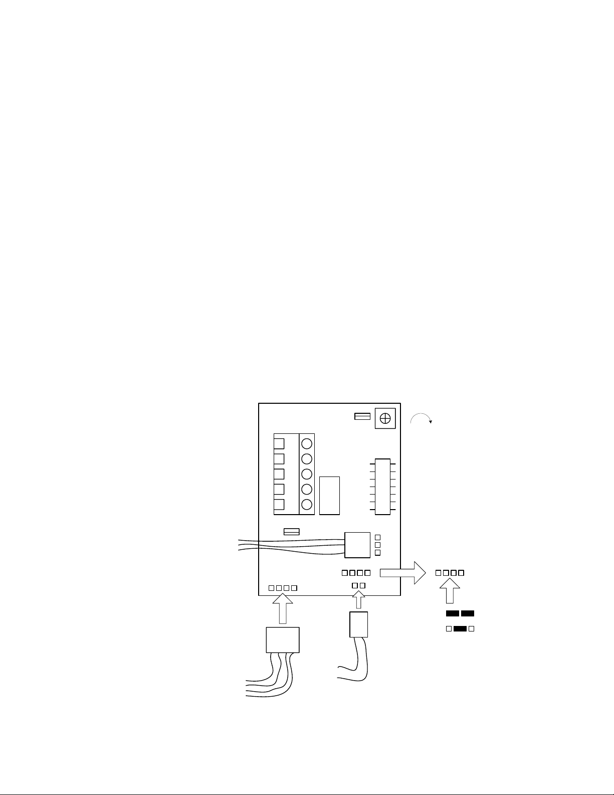
12 VDC POWER
• Requires .5-amp power.
• Connect 12 Volt DC POSITIVE to terminal 1.
• Connect 12 Volt DC NEGATIVE to terminal 2.
• Be sure power select jumpers are set for 12 VDC operation.
24 VDC POWER
• Requires .25-amp power.
• Connect 24 Volt DC POSITIVE to terminal 1.
• Connect 24 Volt DC NEGATIVE to terminal 2.
• Be sure power select jumpers are set for 24 VDC operation.
Lock Status LED and Relay (DKML-S12-1L and DKML-S12-1LT only)
• LOCKED CONDITION - LED glows green and relay activates.
• UNSECURE CONDITION – LED glows red and relay is deactivated.
• Relay contacts are rated for 1 amp at 24 VDC maximum. Do not exceed this rating.
Timer (DKML-S12-1LT only)
• Adjustable from 0-90 seconds.
TIMER
12 or 24 VDC POSITIVE
12 or 24 VDC NEGATIVE
RELAY NORMALLY OPEN
RELAY COMMON
RELAY NORMALLY CLOSED
FROM MAGNET
TO MAGNET
+
1
2
NO
3
C
4
NC
5
WHT
BLK
GRN
RED
L1 L2
J1 J2
TO LED
LED1
GRN
BLK
RED
INCREASE
IMPORTANT!
J1 J2
12 VDC
24 VDC
P/N DKML-065 REV C 5/02
 Loading...