

DoorKing 9500 Series Owner's Manual
Owner’s Manual
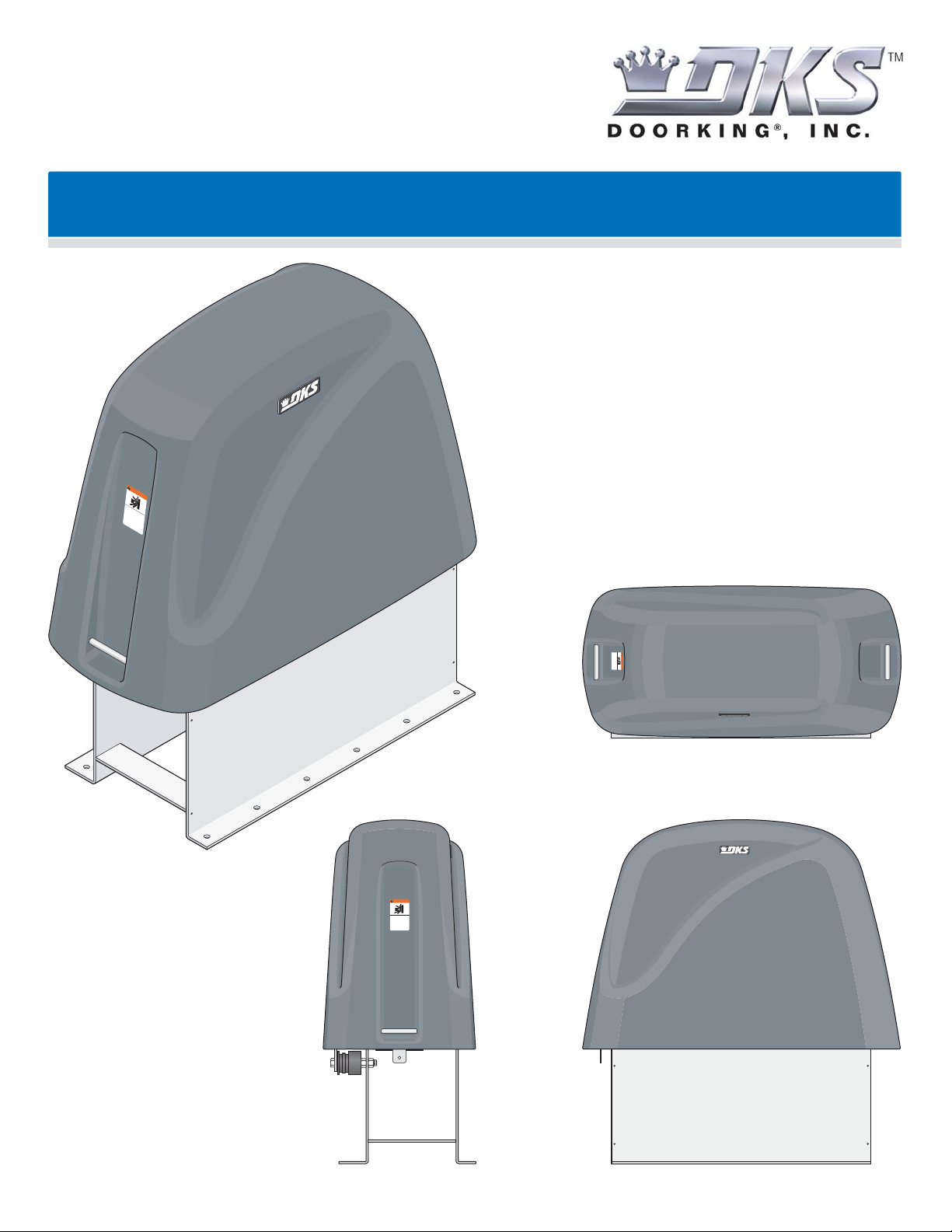
Maximum Security Heavy-Duty Vehicular Slide Gate Operators
WAR
NING
M
OV
SE
IN
G
R
I
G
O
A
U
T
S
Ope
E
I
r
N
C
a
a
t
A
JUR
n
e
d
ga
N
f
r
t
e
e
C
e
Y
on
A
o
OR
f
l
U
y
D
p
o
e
w
S
op
h
no
E
e
D
le
o
n
t
r
a
E
a
g
o
l
nd
a
lo
pe
A
t
e
w
T
r
o
a
a
c
bs
H
r
t
hi
e
e
t
a
l
r
g
D
d
uc
i
a
s
r
o
t
e
e
t
i
no
n
i
n
.
on
t
pa
s
t
o
i
s
s
p
g
t
.
ta
h
ht
l
a
nd
w
y
h
i
n
il
i
n
e
g
g
ga
R
a
a
t
e
e
t
t
e
a
e
a
p
d
i
r
s
e
a
o
a
t
w
m
h
n
o
o
e
v
r
r
i
’
n
w
s
g.
a
m
l
k
a
t
n
hrou
ua
l
a
gh
nd
s
a
f
e
ty
in
s
tr
u
c
t
i
o
ns
.
Series 9500
Series 9500
WARNING
MOVING GATE CAN CAUSE
SERIOUS INJURY OR DEATH
Operate gate only when gate area is in sight
and free of people and obstructions.
Do not allow children to play in gate area
or operate gate.
Do not stand in gate path or walk through
path while gate is moving.
Read owner’s manual and safety instructions.
SERIOUS INJURY OR DEATH
Operate gate only when gate area is in sight
and free of people and obstructions. Do not allow children to play in gate area
or operate gate. Do not stand in gate path or walk through
path while gate is moving. Read owner’s manual and safety instructions.
MOVING GATE CAN CAUSE
WARNING
Copyright 2010 DoorKing, Inc. All rights reserved.

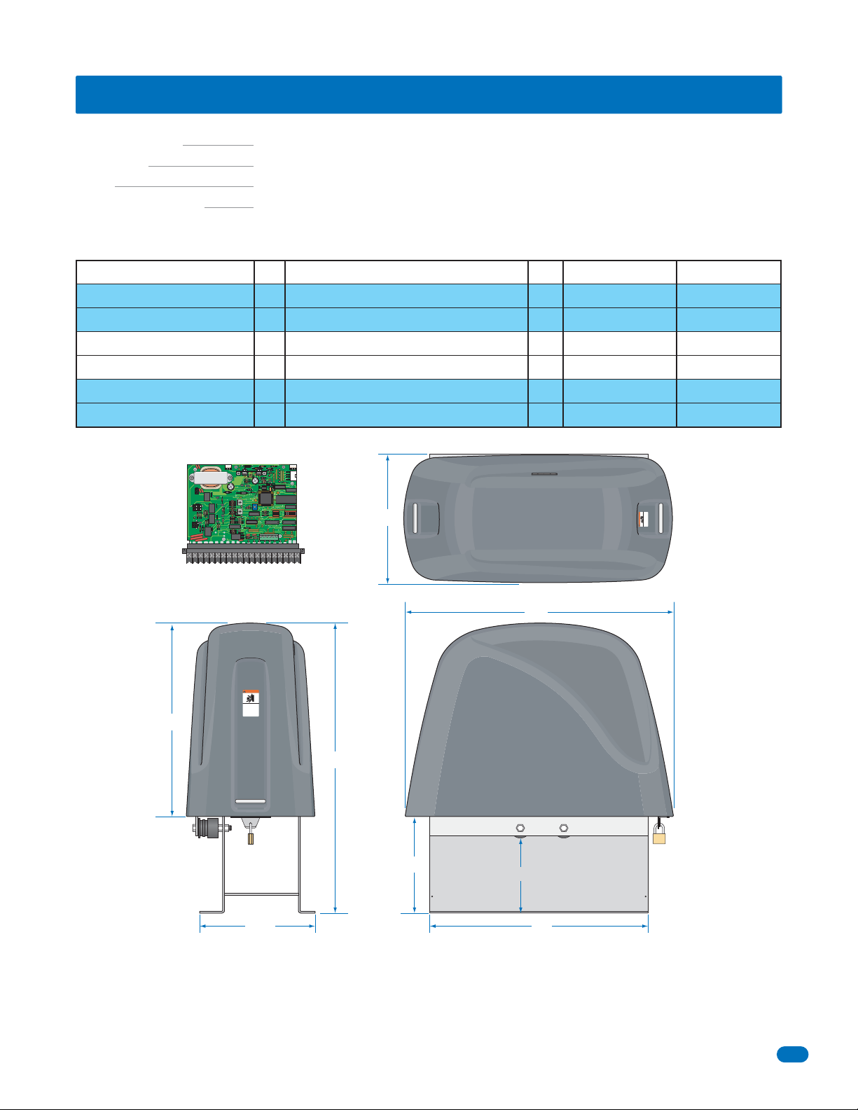
SPECIFICATIONS
g
Class of Operation Series 9500 - UL325 Class III, IV
Type of Gate Vehicular Slide Gates Only
Cycles Continuous
Entrapment Protection Provision for connection of a non-contact sensor (Type B1) and/or a contact sensor (Type B2).
Current sensor system
3 HP - 230 VAC Single-Phase
Gear Ratio - Traveling SpeedAmpHorsepower - Voltage - Phase
40:1 - Speed Controller from 0 to 2 Ft/Sec
17
Max Gate Weight
Installed Level
No
10,000 Lbs.
Max Gate Length
Installed LevelBrake
160 Ft
3 HP - 230 VAC Three-Phase
3 HP - 460 VAC Three-Phase
5 HP - 230 VAC Three-Phase
5 HP - 460 VAC Three-Phase
5 HP - 230 VAC Three-Phase
5 HP - 460 VAC Three-Phase
REVERSE
P8
4404-010
P7P6
20 19 18 17 16 15 14 13 12 11 10 9 8 7 6 5 4 3 2 1
4404-010
Circuit Board
39”
40:1 - Speed Controller from 0 to 2 Ft/Sec
9.2
40:1 - Speed Controller from 0 to 2 Ft/Sec
4.6
40:1 - Speed Controller from 0 to 2 Ft/Sec
12.4
40:1 - Speed Controller from 0 to 2 Ft/Sec
6.2
10:1 - Speed Controller from 0 to 4 Ft/Sec
15.4
10:1 - Speed Controller from 0 to 4 Ft/Sec
8.2
LOOP
REV SENSE
OPEN
REV SENSE
CLOSE
NO
NC
EXIT
LOOP
LMT
LMT
TIME
DELAY
1ON23 41ON23 45 67 8
26”
No
No
No
No
Yes
Yes
10,000 Lbs.
10,000 Lbs.
20,000 Lbs.
20,000 Lbs.
10,000 Lbs.
10,000 Lbs.
WARNING
160 Ft
160 Ft
160 Ft
160 Ft
160 Ft
160 Ft
MOVING GATE CAN CAUSE
Operate gate only when gate area is in sight
and free of people and obstructions.
Do not allow children to play in gate area
or operate gate.
Do not stand in gate path or walk through
path while gate is moving.
Read owner’s manual and safety instructions.
SERIOUS INJURY OR DEATH
54”
WARNING
MOVING GATE CAN CAUSE
SERIOUS INJURY OR DEATH
Operate gate only when gate area is in sight
and free of people and obstructions.
Do not allow children to play in gate area
or operate gate.
Do not stand in gate path or walk through
path while gate is moving.
Read owner’s manual and safety instructions.
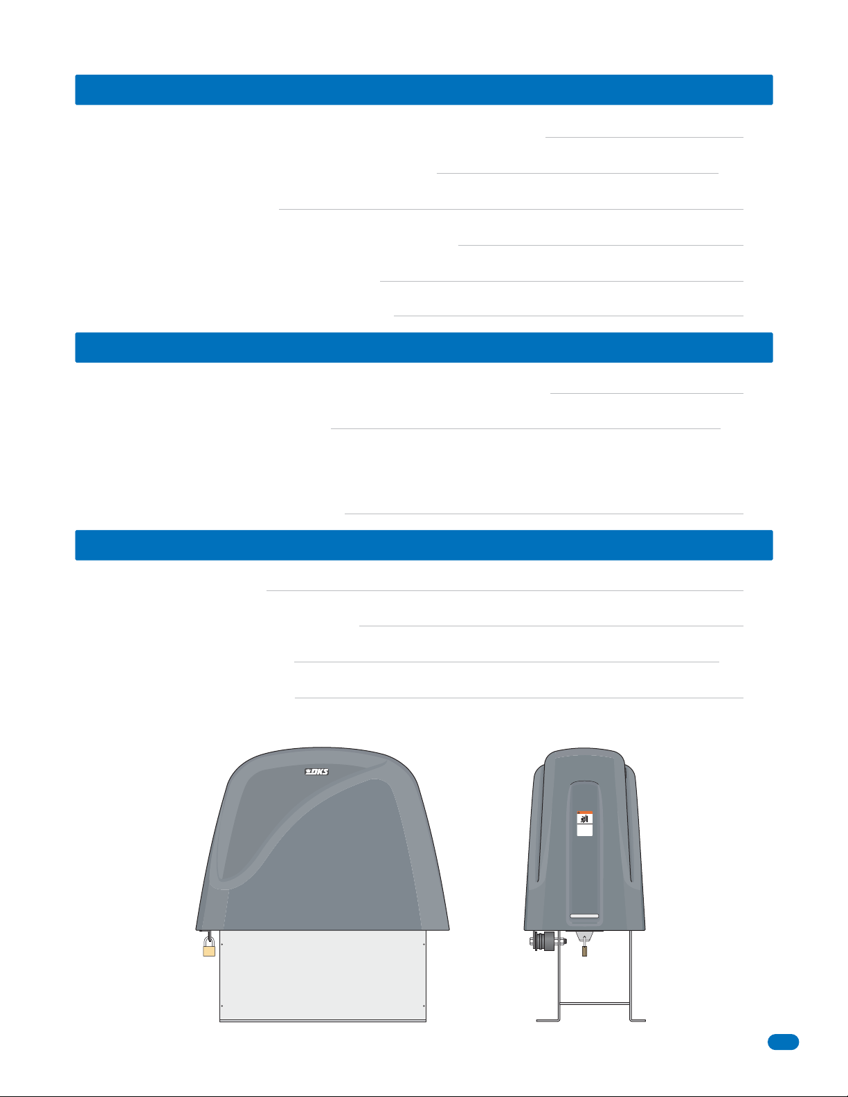
59”
Padlock
Not Provided
23.5”
20”
15”
44”
Use this manual for the 9500 series operators with circuit board 4404-010 Rev A or higher ONLY.
DoorKing, Inc. reserves the right to make changes in the products described in this manual without notice and without obligation of DoorKing, Inc. to notify any
persons of any such revisions or changes. Additionally, DoorKing, Inc. makes no representations or warranties with respect to this manual. This manual is
copyrighted, all rights reserved. No portion of this manual may be copied, reproduced, translated, or reduced to any electronic medium without prior written
consent from DoorKin
9510-065-D-3-10 - Draft - Not for Release
, Inc.
1

SPECIFICATIONS 1
Gate Construction
Important Safety Instructions
Instructions regarding intended installation:
Important Notices
UL325 Entrapment Protection
Glossary
Slide Gate Requirements
Slide Gate Protection
4
4
4
5
6
7
8
9
SECTION 1 - INSTALLATION 10
1.1 Gate Hardware
1.2 Removing Cover
10
10
1.3 Underground Conduit Requirements
1.4 Concrete Pad Description
1.5 Mounting Operator and Chain
1.6 Installation of Chain Tray
1.7 Installation of Warning Signs
10
11
12
13
13
SECTION 2 - WIRING 14
2.1 High Voltage Wire Runs
2.2 High Voltage Terminal Connection
2.3 Main Terminal Description
2.4 UL 325 Terminal for Secondary Entrapment Protection
2.5 Control Wiring
14
14
15
16
17
2.6 Auxiliary Device Wiring
2.7 Loop Detector Wiring
2.8 Primary / Secondary Dual Gate Operators Wiring
2
Draft - Not for Release - 9510-065-D-3-10
18
19
20
SECTION 3 - ADJUSTMENTS 21
3.1 4404 Circuit Board Description and Adjustments
3.2 DIP-Switch SW 1 and SW 2 Settings
3.3 Limit Switches
3.4 Inherent Reverse Sensor Adjustment
3.5 Current Sensor Adjustment
3.6 Speed Controller Adjustment
21
22-23
24
25
25
26
SECTION 4 - OPERATING INSTRUCTIONS 27
4.1 Built-In Controls and Reset Buttons Description
4.2 Shutdown Conditions
Soft Shutdown
Hard Shutdown
4.3 Manual Gate Operation
27
28-29
29
SECTION 5 - MAINTENANCE AND TROUBLESHOOTING 30
5.1 Maintenance
5.2 Built-In Diagnostic Tests
5.3 Troubleshooting
5.4 Accessory Items
MOVING GATE CAN CAUSE
SERIOUS INJURY OR DEATH
Operate gate only when gate area is in sight
and free of people and obstructions.
Do not allow children to play in gate area
or operate gate.
Do not stand in gate path or walk through
path while gate is moving.
Read owner’s manual and safety instructions.
WARNING
30
31
31-32
33
9510-065-D-3-10 - Draft - Not for Release
3

Gate Construction
Vehicular gates should be constructed and installed in accordance with ASTM F2200; Standard Specification for Automated
Vehicular Gate Construction. For a copy of this standard, contact ASTM directly at 610-832-9585; service@astm.org; or
www.astm.org.
Important Safety Instructions
WARNING - To reduce the risk of injury or death:
1. READ AND FOLLOW ALL INSTRUCTIONS.
2. Never let children operate or play with gate controls. Keep the remote control away from children.
3. Always keep people and objects away from gate. NO ONE SHOULD CROSS THE PATH OF THE MOVING GATE.
4. Test the operator monthly. The gate MUST reverse on contact with a rigid object or stop or reverse when an object
activates the non-contact sensors. After adjusting the force or the limit of travel, retest the gate operator. Failure to adjust
and retest the gate operator properly can increase the risk of injury or death.
5. Use the emergency release only when the gate is not moving.
6. KEEP GATES PROPERLY MAINTAINED. Read the owner's manual. Have a qualified service person make repairs to gate
hardware.
7. The entrance is for vehicles only. Pedestrians must use separate entrance.
8. SAVE THESE INSTRUCTIONS!
Instructions regarding intended installation:
• Install the gate operator only if:
1. The operator is appropriate for the construction of the gate and the usage class of the gate.
2. All openings of a horizontal slide gate are guarded or screened from the bottom of the gate to a minimum of 4 feet
(1.22 m) above the ground to prevent a 2 ¼ inch (57.2 mm) diameter sphere from passing through the openings
anywhere in the gate, and in that portion of the adjacent fence that the gate covers in the open position.
3. All exposed pinch points are eliminated or guarded.
4. Guarding is supplied for exposed rollers.
• The operator is intended for installation only on gates used for vehicles. Pedestrians must be supplied with a separate
access opening. The pedestrian access opening shall be designed to promote pedestrian usage. Locate the gate such that
persons will not come in contact with the vehicular gate during the entire path of travel of the vehicular gate.
• The gate must be installed in a location so that enough clearance is supplied between the gate and adjacent structures
when opening and closing to reduce the risk of entrapment. Swinging gates should not open into public access areas.
• The gate must be properly installed and work freely in both directions prior to the installation of the gate operator. Do not
over-tighten the operator clutch, pressure relief valve or reduce reversing sensitivity to compensate for a damaged gate.
• For gate operators utilizing Type D protection:
1. The gate operator controls must be placed so that the user has full view of the gate area when the gate is moving.
2. A warning placard shall be placed adjacent to the controls.
3. An automatic closing device (such as a timer, loop sensor, or similar device) shall not be employed.
4. No other activation device shall be connected.
• Controls intended for user activation must be located at least ten feet (10’) away from any moving part of the gate and
where the user is prevented from reaching over, under, around or through the gate to operate the controls. Outdoor or
easily accessible controls should have a security feature to prevent unauthorized use.
• The Stop and/or Reset button must be located in the line-of-sight of the gate. Activation of the reset control shall not
cause the operator to start.
• A minimum of two (2) WARNING SIGNS shall be installed, one on each side of the gate where easily visible.
• For gate operators utilizing a non-contact sensor:
1. See the instructions on the placement of non-contact sensors for each type of application.
2. Care shall be exercised to reduce the risk of nuisance tripping, such as when a vehicle trips the sensor while the gate
is still moving in the opening direction.
3. One or more non-contact sensors shall be located where the risk of entrapment or obstruction exist, such as the
perimeter reachable by a moving gate or barrier.
4
Draft - Not for Release - 9510-065-D-3-10

• For gate operators utilizing contact sensors:
1. One or more contact sensors shall be located where the risk of entrapment or obstruction exist, such as at the
leading edge, trailing edge, and post mounted both inside and outside of a vehicular horizontal slide gate.
2. One or more contact sensors shall be located at the bottom edge of a vehicular vertical lift gate.
3. One or more contact sensors shall be located at the pinch point of a vehicular vertical pivot gate.
4. A hardwired contact sensor shall be located and its wiring arranged so that the communication between the sensor
and the gate operator is not subjected to mechanical damage.
5. A wireless contact sensor such as one that transmits radio frequency (RF) signals to the gate operator for
entrapment protection functions shall be located where the transmission of the signals are not obstructed or
impeded by building structures, natural landscaping or similar obstructions. A wireless contact sensor shall function
under the intended end-use conditions.
6. One or more contact sensors shall be located at the bottom edge of a vertical barrier (arm).
Important Notices
Vehicular gate operator products provide convenience and security. However, gate operators must use high levels of force
to move gates and most people underestimate the power of these systems and do not realize the potential hazards associated with an incorrectly designed or installed system. These hazards may include:
• Pinch points
• Entrapment areas
• Reach through hazards
• Absence of entrapment protection devices
• Improperly located access controls
• Absence of vehicle protection devices
• Absence of controlled pedestrian access
In addition to these potential hazards, automated vehicular gate systems must be installed in accordance with the UL-325
Safety Standard and the ASTM F2200 Construction Standard. Most lay persons are unaware of, or are not familiar with,
these standards. If an automated vehicular gate system is not properly designed, installed, used and maintained, serious
injuries or death can result. Be sure that the installer has instructed you on the proper operation of the gate and gate
operator system.
Be sure that the installer has trained you about the basic functions of the required reversing systems associated with your
gate operating system and how to test them. These include reversing loops, inherent reversing system, electric edges,
photoelectric cells, or other external devices.
• This Owner’s Manual is your property. Keep it in a safe place for future reference.
• Be sure that all access control devices are installed a minimum distance of 10 feet away from the gate and gate
operator, or in such a way that a person cannot touch the gate or gate operator while using the device. If access
control devices are installed in violation of these restrictions, immediately remove the gate operator from service
and contact your installing dealer.
• Loops and loop detectors, photo-cells or other equivalent devices must be installed to prevent the gate from
closing on vehicular traffic.
• The speed limit for vehicular traffic through the gate area is 5 MPH. Install speed bumps and signs to keep
vehicular traffic from speeding through the gate area. Failure to adhere to posted speed limits can result in
damage to the gate, gate operator, and to the vehicle.
• Be sure that all persons who will use the gate system are familiar with the proper use of the gate and gate
operator and are familiar with the possible hazards associated with the gate system.
• Be sure that warning signs are permanently installed on both sides of the gate in an area where they are fully
visible to traffic.
• It is your responsibility to periodically check all entrapment protection devices. If any of these devices are
observed to function improperly, remove the operator from service immediately and contact your installing or
servicing dealer.
• Follow the recommended maintenance schedule.
• Do not allow children to play in the area of the operator or to play with any gate-operating device.
• To remove the gate operator from service, operate the gate to the full open position and then shut off power to
the operator at the service panel.
9510-065-D-3-10 - Draft - Not for Release
5
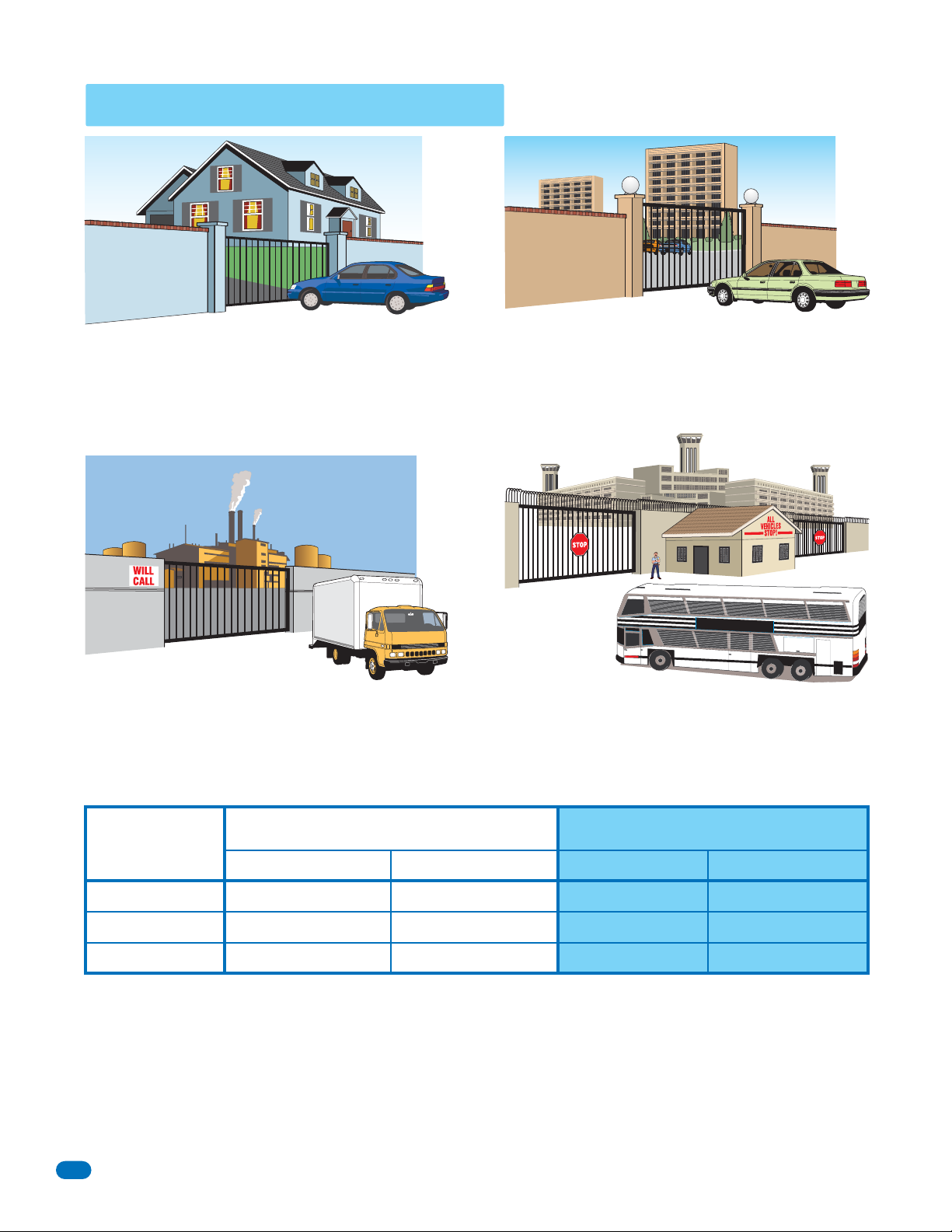
UL325 Entrapment Protection
Class I
A vehicular gate operator (or system) intended for use in a
home of one-to four single family dwelling, or a garage or
parking area associated therewith.
Class II
A vehicular gate operator (or system) intended for use in a
commercial location or building such as a multi-family
housing unit (five or more single family units) hotel,
garages, retail store or other building servicing the general
public.
Class III Class IV
A vehicular gate operator (or system) intended for use in a
industrial location or building such as a factory or loading
dock area or other locations not intended to service the
general public.
A vehicular gate operator (or system) intended for use in a
guarded industrial location or building such as an airport
security area or other restricted access locations not
servicing the general public, in which unauthorized access
is prevented via supervision by security personnel.
STA
TE
PR
ISON
This table illustrates the entrapment protection requirements for each of the four UL325 classes.
UL325
Classifications
Class I and II
Class III
Class IV
A - Inherent entrapment protection system.
B1 - Provision for connection of, or supplied with, a non-contact sensor (photoelectric sensor or the equivalent).
When used as the PRIMARY device, must be monitored.
B2 - Provision for connection of, or supplied with, a contact sensor (edge device or the equivalent).
When used as the PRIMARY device, must be monitored.
C - Inherent adjustable clutch or pressure relief device.
D - Provision for connection of, or supplied with, an actuating device requiring continuous pressure to maintain
opening or closing motion of the gate.
E - An inherent audio alarm.
6
Horizontal Slide, Vertical Lift, Vertical Pivot Swing and Vertical Barrier (arm)
Primary Protection
A B1, B2 or D A, B1, B2, C or DA or C
A, B1 or B2 A, B1, B2, D or E A, B1, B2, C or DA, B1, B2 or C
A, B1, B2 or D A, B1, B2, D or E A, B1, B2, C, D or EA, B1, B2, C or D
Secondary Protection Primary Protection Secondary Protection
Draft - Not for Release - 9510-065-D-3-10

Glossary
GATE - A moving barrier such as a swinging, sliding, raising, lowering, or the like, barrier, that is a stand-alone passage
barrier or is that portion of a wall or fence system that controls entrance and/or egress by persons or vehicles and
completes the perimeter of a defined area.
RESIDENTIAL VEHICULAR GATE OPERATOR – CLASS I - A vehicular gate operator (or system) intended for use in a home
of one-to four single family dwelling, or garage or parking area associated therewith.
COMMERCIAL / GENERAL ACCESS VEHICULAR GATE OPERATOR - CLASS II - A vehicular gate operator (or system)
intended for use in a commercial location or building such as a multi-family housing unit (five or more single family units),
hotels, garages, retail store, or other building servicing the general public.
INDUSTRIAL / LIMITED ACCESS VEHICULAR GATE OPERATOR - CLASS III - A vehicular gate operator (or system)
intended for use in an industrial location or building such as a factory or loading dock area or other locations not intended
to service the general public.
RESTRICTED ACCESS VEHICULAR GATE OPERATOR - CLASS IV - A vehicular gate operator (or system) intended for use in
a guarded industrial location or building such as an airport security area or other restricted access locations not servicing
the general public, in which unauthorized access is prevented via supervision by security personnel.
VEHICULAR BARRIER (ARM) OPERATOR (OR SYSTEM) - An operator (or system) that controls a cantilever type device (or
system), consisting of a mechanical arm or barrier that moves in a vertical arc, intended for vehicular traffic flow at
entrances or exits to areas such as parking garages, lots or toll areas.
VEHICULAR HORIZONTAL SLIDE-GATE OPERATOR (OR SYSTEM) - A vehicular gate operator (or system) that controls a
gate which slides in a horizontal direction that is intended for use for vehicular entrance and exit to a drive, parking lot, or
the like.
VEHICULAR SWING-GATE OPERATOR (OR SYSTEM) - A vehicular gate operator (or system) that controls a gate which
moves in an arc in a horizontal plane that is intended for use for vehicular entrance and exit to a drive, parking lot, or the
like.
SYSTEM - In the context of these requirements, a system refers to a group of interacting devices intended to perform a
common function.
WIRED CONTROL - A control implemented in a form of fixed physical interconnections between the control, the associated
devices, and an operator to perform predetermined functions in response to input signals.
WIRELESS CONTROL - A control implemented in means other than fixed physical interconnections (such as radio waves or
infrared beams) between the control, the associated devices, and an operator to perform predetermined functions in
response to input signals.
INHERENT ENTRAPMENT PROTECTION SYSTEM - A system, examples being a motor current or speed sensing system,
which provides protection against entrapment upon sensing an object and is incorporated as a permanent and integral part
of the operator.
EXTERNAL ENTRAPMENT PROTECTION DEVICE - A device, examples being an edge sensor, a photoelectric sensor, or
similar entrapment protection device, which provides protection against entrapment when activated and is not incorporated
as a permanent part of an operator.
ENTRAPMENT - The condition when an object is caught or held in a position that increases the risk of injury.
9510-065-D-3-10 - Draft - Not for Release
7
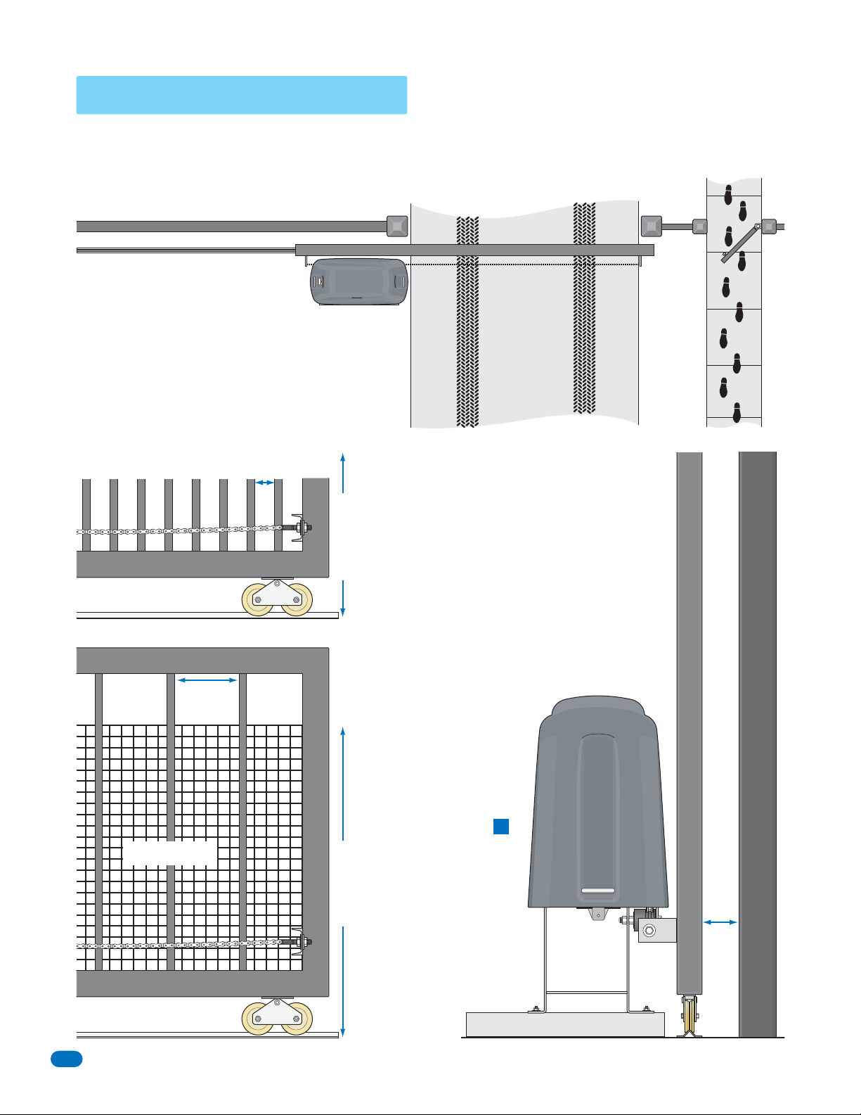
Slide Gate Requirements
The operator is intended for installation only on gates used for vehicles. Pedestrians must be supplied with a separate
access opening. The pedestrian access opening shall be designed to promote pedestrian usage. Locate the gate such that
persons will not come in contact with the vehicular gate during the entire path of travel of the vehicular gate.
(ref. UL325 56.8.4.b)
Adjacent fence that covers open gate position.
X X X X X X X X X X X X X X X X X X X X X X X X X X X X X X X X X X X X X X X X X X X X X X X X X X X X X X X X X X X X X
High Risk of Entrapment Area
X X X
All openings of a horizontal slide gate are guarded or
screened from the bottom of the gate to a minimum
of four (4) feet (1.22 m) above the ground to
prevent a 2 1/4 inch (57.2 mm) diameter sphere
from passing through the openings anywhere in the
gate and in that portion of the adjacent fence that
the gate covers in the open position.(ref. UL325
56.8.4.a.2 and ASTM F2200 6.1.2)
Compliant openings less than 2 1/4”.
Gate Frame and Adjacent Fence Area
Drawings NOT to scale.
Fence
X X XX X XX X XX X XX X XX X X X X XX X X
X X X X X X X X X X X X X X X X X X X X X X X X X X X X X X X X X X X X X X X X X X X X X X X X X X X X X X X X X X X X X X X X X X X X X
SERIOUS INJURY OR DEATH
Operate gate only when gate area is in sight
and free of people and obstructions. Do not allow children to play in gate area
or operate gate. Do not stand in gate path or walk through
path while gate is moving. Read owner’s manual and safety instructions.
MOVING GATE CAN CAUSE
WARNING
Closed Gate
A gap, measured in the horizontal
plane parallel to the roadway, between
a fixed stationary object nearest the
roadway (such as a gate support post)
and the gate frame when the gate is in
either the fully open position or the
fully closed position, shall not exceed
4 ft. minimum
2 1/4 inch (57.2 mm).
(ref. ASTM F2200 6.1.4)
Non-compliant openings
Wider
than
2 1/4”
Screened Wire Mesh
less than 2 1/4”.
Gate Frame and Adjacent Fence Area
Note: Install
screened wire
mesh to an
existing
non-compliant
gate and the
adjacent fence
that covers
4 ft. minimum
open gate
position
(See above).
Note: A filler post or barrier may
need to be installed in the gap area
to reduce the distance to 2 1/4
inches or less.
A contact
sensor
should be
installed in
this area
for safety.
(See
A
on next
page).
High Risk of Entrapment Area
Gate Frame
Gate Support Post
2 1/4” maximum gap area
8
Draft - Not for Release - 9510-065-D-3-10
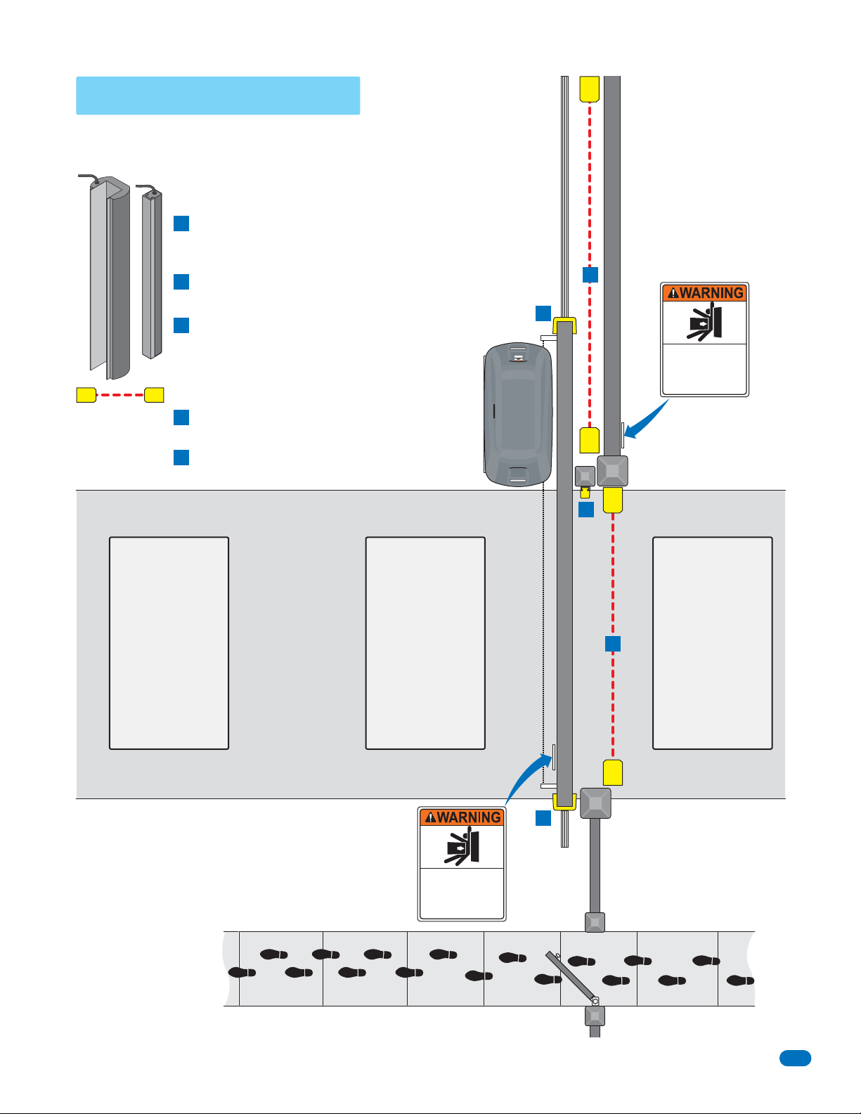
Slide Gate Protection
Entrapment protection devices are required to reduce the risk of injury. Install sensors
where the risk of entrapment or obstruction exists while gate is moving. Individual
requirements will vary.
Contact Sensor (Reversing Edges)
Installed on the fence to help minimize the potential of
A
entrapment between the gate and fence. A filler post or
barrier may need to be installed between fence and gate.
Helps minimize the potential of entrapment during
B
the back travel of the gate.
Minimizes the potential of the gate closing on
C
vehicular or other traffic that loops cannot sense.
Non-Contact Sensors (Photocells)
Minimizes the potential of the gate closing on
1
vehicular or other traffic that loops cannot sense.
Helps minimize the potential of entrapment during
2
the back travel of the gate.
B
Read owner’s manual and safety instructions.
path while gate is moving.
Do not stand in gate path or walk through
or operate gate.
Do not allow children to play in gate area
and free of people and obstructions.
Operate gate only when gate area is in sight
SERIOUS INJURY OR DEATH
MOVING GATE CAN CAUSE
WARNING
2
Fence
Warning Signs
Permanently mounted
and easily visible from
either side of the gate.
Moving Gate Can Cause
Serious Injury or Death
KEEP CLEAR! Gate may move at any time
without prior warning.
Do not let children operate the gate or play
in the gate area.
This entrance is for vehicles only.
Pedestrians must use separate entrance.
Automatic
Exit Loop
(Optional) will
provide an open
command to the
gate operator(s)
when a vehicle
is exiting the
property.
Separate
Pedestrian
Walkway
Located so pedestrians
cannot come in contact
with the vehicular gate.
Reverse
Minimizes the
potential of the
gate closing when
a vehicle is
present. Number
and placement of
loops is dependent
on the application.
Warning Signs
Permanently mounted
and easily visible from
either side of the gate.
Loop
Moving Gate Can Cause
Serious Injury or Death
KEEP CLEAR! Gate may move at any time
without prior warning.
Do not let children operate the gate or play
in the gate area.
This entrance is for vehicles only.
Pedestrians must use separate entrance.
Closed Gate
C
A
Fence
Reverse
Loop
Minimizes the
potential of the
1
gate closing when
a vehicle is
present. Number
and placement of
loops is dependent
on the application.
9510-065-D-3-10 - Draft - Not for Release
9
 Loading...