

DoorKing 9411 Single Channel with Aux Relay, 9410 Single Channel, 9409 Dual Channel Information Manual
Information Manual
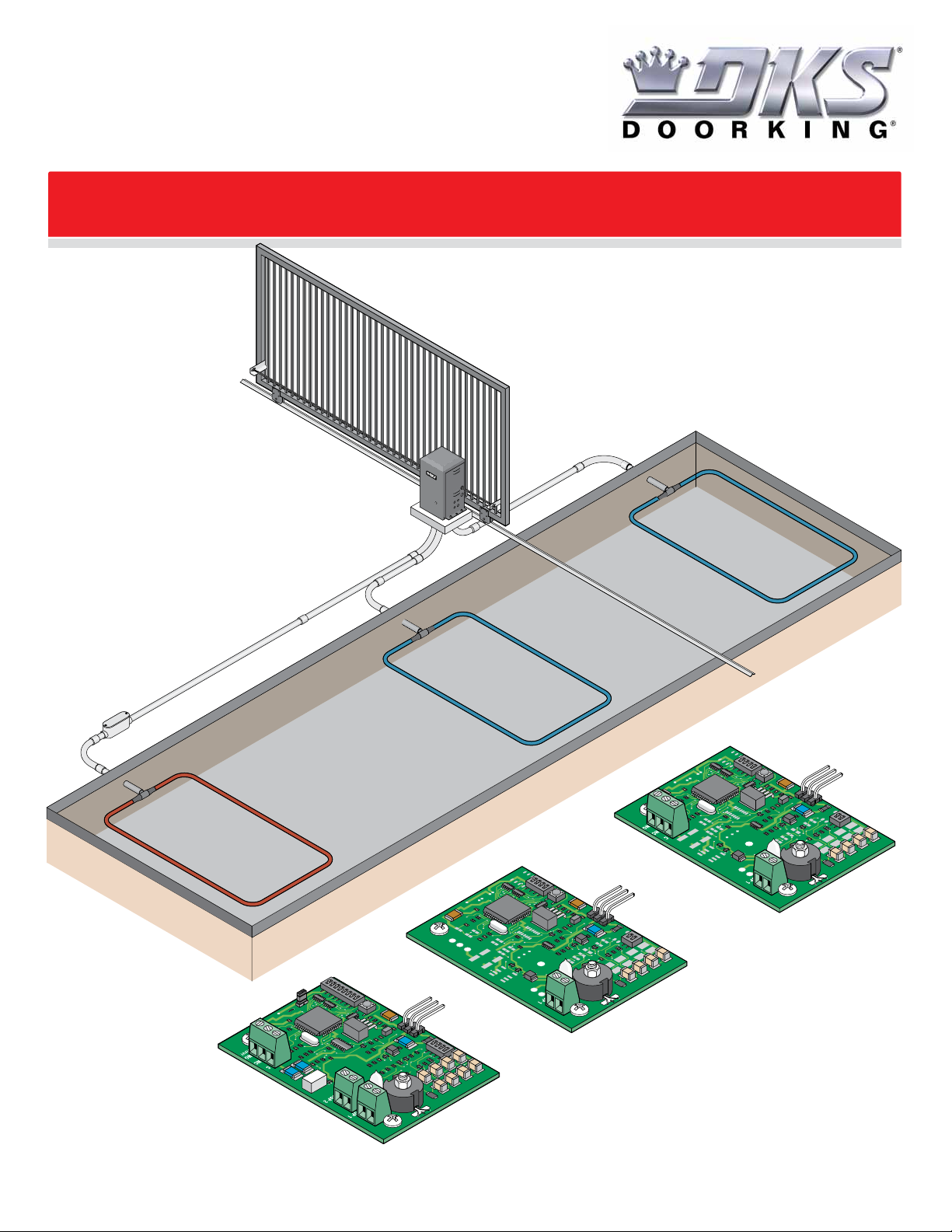
Underground Loops and Loop Detectors
Underground Loops and Loop Detectors
DoorKing Plug-In Loop Detectors and Loop Accessories
9409 Dual Channel
9411 Single Channel
with Aux Relay
9410 Single Channel
Copyright 2016 DoorKing, Inc. All rights reserved.


INTRODUCTION 2
Underground Loop
Lead-In Wire or Cable
Loop Detector
Design Facts
2
2
2
2-3
SECTION 1 - HOW THE LOOP SYSTEM WORKS 4
Field of Sensitivity
Height of Detection
Field Cancellation Effect
Field Enhancement Effect
Loop Phasing
Electrically Reverse the Phase of a Loop
Loop Detection Field Interference and Loop Placement
4
4
5
5
6
6
7
SECTION 2 - LOOP INSTALLATION GUIDELINES 8
Saw Cut Loop Guidelines
DoorKing Preformed Loop Guidelines
8-9
10
SECTION 3 - TYPICAL LOOP LAYOUT EXAMPLES 11
Slide Gates
Swing Gates
11
12
SECTION 4 - TROUBLESHOOTING LOOP SYSTEMS 13
Loop Diagnostics
Poor Connections
Shorted Loop Wire
Detector Adjustments
13
13
13
13
SECTION 5 - DOORKING LOOP DETECTORS AND ACCESSORIES 14
Loop Info-Q-2-16
1
INTRODUCTION
A loop detection system is a method of sensing vehicles and is typically used in automated gate applications to prevent a
gate from automatically closing on a vehicle or to automatically open the gate when a vehicle is exiting a property. Vehicle
loops can also be used to activate card readers, ticket spitters, etc. When properly installed, loops are an extremely
reliable form of vehicle detection. The loop detection system operates by creating an electrical field of sensitivity that
tunes to the surrounding environment. When a metallic object enters this electrical field, the loop detector senses a
change in the field and generates an output, usually activating a relay in a gate operator or other access control device that
controls the operation of the gate.
There are three basic components in a loop detection system:
• Underground loop
• Loop lead-in wire or cable
• Loop detector
Operator Chassis Ground
grounding restrictions).
Short Leg Length
Loop with
3 Wire Turns
(See page 6 for
Long Leg Length
PVC Conduit
in Watertight J-Box
Underground Loop
The loop is made from a continuous
piece of wire (NO SPLICES) that is
coiled around for a number of turns
in a square or rectangular pattern.
The wire is embedded into pavement
either as a preformed loop placed
prior to paving, or into a saw cut that
is cut into existing pavement. Both
ends of this wire are then extended
to the edge of the pavement.
Design Facts
Proper installation of the loops is essential for reliable functioning of the detector system. Most detector problems are caused
by improper loop installation! The geometry (size and shape) of the loop defines the detection zone characteristics.
Loop Lead-In Wire or Cable
The lead-in wire or cable extends the two
ends of the loop wire back to the loop
detector. On short runs (Loop is within ten
feet from the loop detector), the two wires
exiting the loop can be twisted together,
run in conduit to the operator and
connected directly to the loop detector.
The lead-in wire: DoorKing recommends
that lead-in wire be twisted a minimum of six turns per foot.
The lead-in cable: If additional lead-in wire is required, DoorKing recommends that you
use a shielded twisted pair (Insulated (floated) at one end and grounded at gate operator) with a direct burial rated jacket or be placed in PVC conduit. All splices must be
soldered and placed in a watertight J-box.
Soldered Spliced Connections
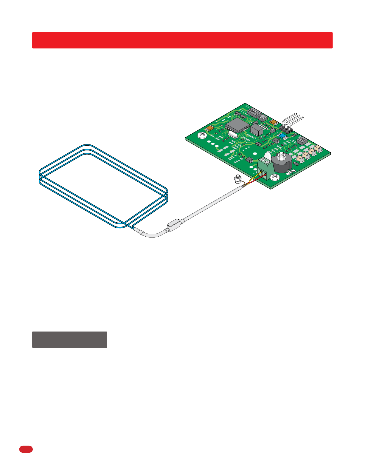
Loop Detector
The loop detector is the electronic
component that controls the loop
system. DoorKing offers loop detectors
(Models 9409, 9410 and 9411) that plug
directly into the gate operator control
board, eliminating the wire harness and
wiring connections other than the loop
lead-in wires. These detector boards have
a terminal strip where the loop lead-in
wire connects. There are also various
other types of standalone detectors
available on the market that can be hard
wired into the gate operator control
board.
• Loop size may vary and will depend on lane width, traffic patterns, and types of vehicles to be detected.
• The short leg of any loop used for vehicle detection should never be less than 18 in. The height of detection is directly
related to the length of the short leg of the loop. A general rule of thumb to follow is that the height of detection is
1/2 to 2/3 the length of the short leg of the loop.
• Normal loops (4 ft x 8 ft) are used to detect motorcycles and automobiles. Minimum size for loops to detect typical
vehicular traffic is 18 in x 48 in. It is always recommended to use a larger loop whenever possible.
• Maximum “detection height” of a loop is 3 to 4', which may be achieved with a loop measuring 6' on the short leg.
• Loops can be saw cut into concrete or asphalt. They can be placed under brick pavers and asphalt or be imbedded in a
poured concrete road surface.
2
Loop Info-Q-2-16
Loops that are physically adjacent to each other and operating on separate loop detectors may interfere (cross-talk) with each
other if they are operating on the same frequencies. Changing the operating frequency on one of the loop detectors can
eliminate this interference. (See page 7 for more information)
When connecting two loops to a single loop detector terminal, always connect the loops in series. If the loops are close
together, the direction of the windings should be considered. Loops physically near each other and wound in the same direction
electrically (i.e. both Clockwise or Counter-Clockwise) will cause field cancellation effects (a dead zone) between the loops. This
may be desirable when two loops (reverse loops) are placed on each side of a sliding gate. Wiring the loops in this manner will
allow the gate to slide between the two loops without causing the loops to detect the gate. If the loops are wound in electrically
opposite directions (i.e. one Clockwise and one Counter-Clockwise), field enhancement will occur between the loops, effectively
extending the field of sensitivity for the loop system. (See pages 5 and 6 for more information)
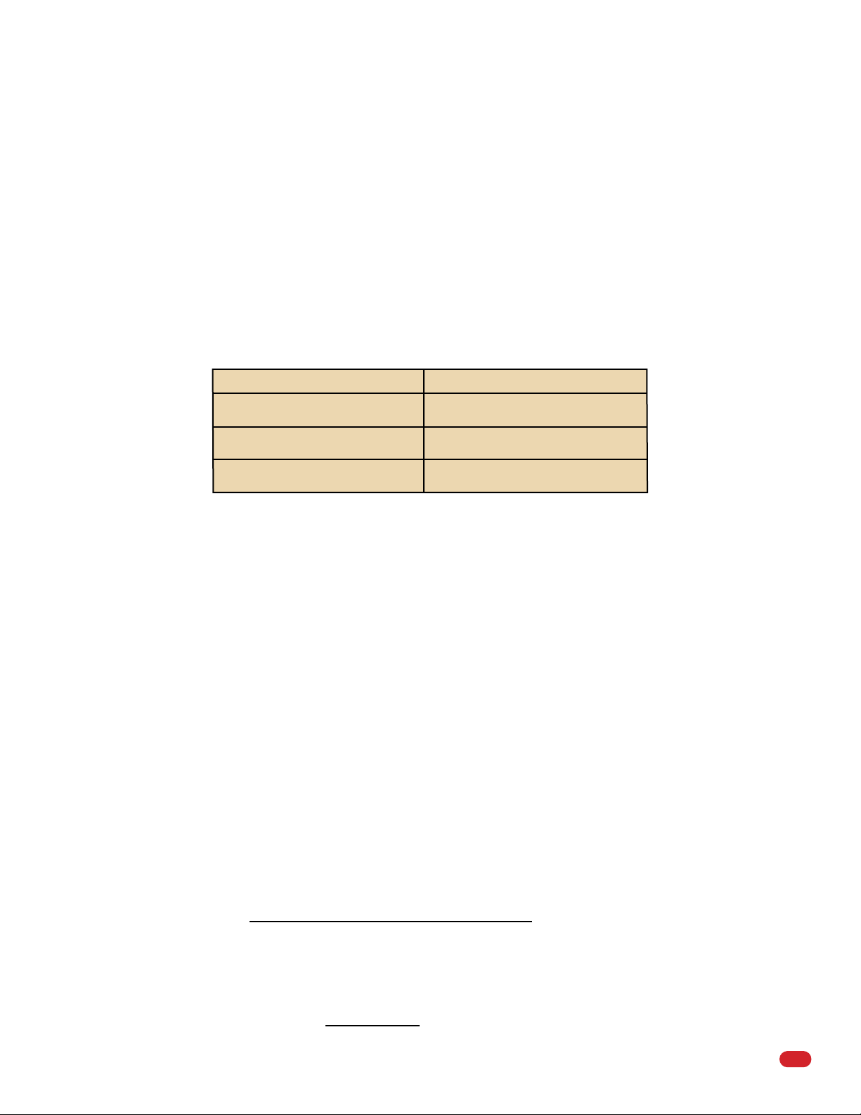
Determine the Number of Wire Turns Required for Each Loop
Loop area (Sq. Ft.) - Multiply loop width by loop length.
Loop Area in Square Feet Number of Turns Required
6 - 12
12 - 60
60 - 240
Note: The number of turns should be increased by 1 turn if lead-in wire or cable length is 500 ft or greater.
• During the construction of new installations (i.e. concrete or asphalt), a pre-formed loop may be used as an alternate to
the saw cut type. Pre-formed loops are typically encased in PVC or other durable materials to provide high reliability and
long life. Sizes may vary depending on the source of the pre-formed loop. DoorKing offers a variety of pre-formed loops
that come with 25 feet of lead-in wire. (See page 10 for more information)
6
4
3
• The loop will tune to its environment. Stationary or static metal objects, such as conduits, pipes, metal grates, etc., will
not affect the loop field. High voltage electrical power lines, either underground or overhead, can affect the loop field.
In addition, fluctuating electrical fields, such as heating coils, can cause loop lock-ups and false detection.
• A heavy grid of reinforcing bars (re-bar) may affect the loop field. To minimize this, DO NOT place a loop directly on the
rebar. Support the loop 1 - 2 inches above the rebar. If possible, make cuts or bends in the rebar grid directly below the
loop. Bars and electrical wires running at angles to the loop have less effect on the loop than those running parallel to the
loop wires. (See page 10 for more information)
• If a single loop is used with a long lead-in cable (500 feet or greater), it is advisable to add an additional turn in the loop.
This increases the ratio of the loop inductance to the total inductance, thereby improving loop sensitivity and overall loop
system stability.
• The inductance of the loop (in micro henries) must fall within the tuning range of the loop detector for the loop system to
operate properly. This is typically not a problem since most loop detectors have a very wide tuning range (20 - 2500
micro henries) and can accommodate most size loops.
To calculate the inductance of a loop use this formula:
Side 1 + Side 2 + Side 3 + Side 4 ) Number of Turns2 = Inductance
(
2
Example: To calculate the inductance of a typical 6 x 8 foot loop with four turns of wire:
6 + 8 + 6 + 8 ) 42 = 224 Micro Henries
(
2
Loop Info-Q-2-16
3
SECTION 1 - HOW THE LOOP SYSTEM WORKS
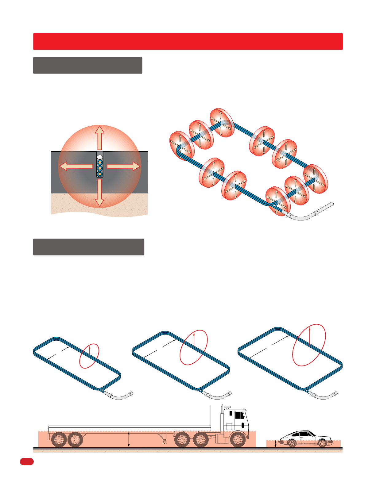
Field of Sensitivity
A loop sets up an inductive field, called a field of sensitivity. This field of sensitivity completely surrounds the loop wires
extending above, below, and on all sides of the loop. When a vehicle (or any metallic object) enters this field of sensitivity, the
inductance of the loop changes as more of the inductive field is disrupted by the vehicle. Once the disruption of the inductive
field is high enough, the loop detector senses this change and outputs a signal, usually in the form of a dry contact relay switch
activation.
Sensitivity Field
Roadway
3 Turn
Saw Cut Loop
Cutaway of Underground Loop
Inductive Field of Sensitivity
Height of Detection
The height of the field of sensitivity, and therefore the height of detection, is determined by the size of the loop. The height
of detection is especially important when you need to detect a high bed truck, which requires more height than a passenger car.
The height of detection above (and below) the loop is determined by the shortest leg of the loop. The height of detection is
equal to 1/2 to 2/3 the length of the SHORT LEG. For example, a four-foot by eight-foot loop will give you approximately 2-1/2
feet of detection height, whereas a six-foot by eight-foot loop will give you approximately 4-feet of detection height. The short
leg of a loop used for vehicle detection should never be shorter than 18 in. The maximum “detection height” of a loop is
6-feet on the short leg. If larger loops are used, the “detectable height” of the loop will NOT increase.
Maximum Detection Height
Approx. 4 ft.
6’
o
ng
L
eg
18”
Short Leg
L
Detection Height
Approx. 1 ft.
M
in.
ong
L
eg
5’
Short Leg
L
o
ng
Detection Height
Approx. 3 ft.
L
eg
Short Leg
L
Larger short leg needed to detect trailer height vs. car height.
4
Loop Info-Q-2-16
 Loading...