

DoorKing 9245 Installation & Owner's Manual
Installation/Owner’s Manual
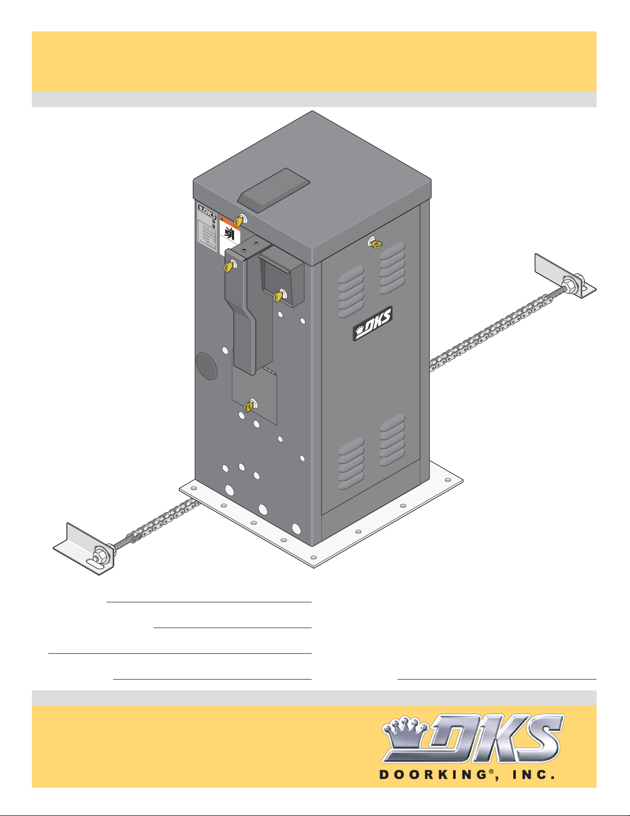
9245
Heavy-Duty Vehicular Slide Gate Operator
9245
9245
Use this manual for circuit board 4404-010 Revision A or higher.
C
ONFO
ANSI/UL-
RM
S
TO
3
C
C
25
A
ER
N/
TIFIED TO
C
SA C
WARNING
V
2
2.2
EHICULA
NO. 2
53382
C
LA
47
R
S
S
GA
T
E OP
M
ODEL
E
R
ATOR
S
ERIAL
HP
V
OLT
S
A
M
P
S
M
M
O
A
P
X
V
HA
SERIOUS INJURY OR DEATH
GA
ING GATE CAN CAUSE
S
T
E
E LOAD
D
6
Oper
o
0 Hz
o
rKin
a
and
t
e
g
ga
f
, I
ree
t
n
e
only
c
of
., I
D
p
n
o
e
w
g
n
o
h
l
ple
ot
e
en gat
or oper
wo
a
a
l
low ch
nd o
o
d
e
, CA
are
a
bs
t
e
i
Do not
t
a
l
ga
r
dre
u
i
s
t
c
e
i
t
n
.
ion
n
path w
t
s
o p
s
s
i
ght
t
.
a
l
nd in gat
a
y
hil
in gat
e
ga
Re
t
a
e
e
e
d owner
a
pa
i
s
r
e
m
t
a
h or walk t
o
v
i
’
ng.
s
man
hrou
ua
l
and s
gh
afe
t
y
ins
t
ructi
o
ns
.
9245-065-C-4-12
Leave Manual with Owner
Date Installed:
Installer/Company Name:
Phone Number:
UL 325 Compliant
Circuit Board
Serial Number
and Revision Letter:
Copyright 2012 DoorKing, Inc. All rights reserved.
TM
Copyright 2009 DoorKing, Inc. All rights reserved.

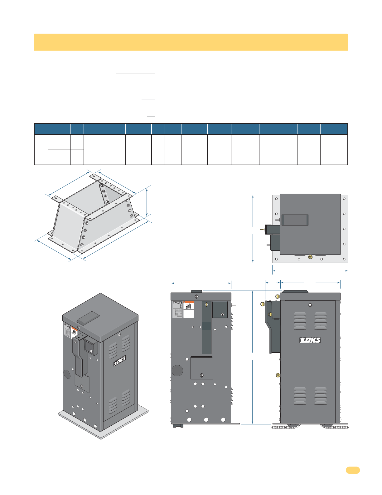
SPECIFICATIONS
Class of Operation Series 9245 - UL 325 Class III, IV
Type of Gate Vehicular Slide Gates Only
Operating Temperature 10° F to 140° F (-12° C to 62° C)
“Optional” heater kits recommended for colder temperatures.
Entrapment Protection Provision for connection of a non-contact sensor (Type B1)
and/or a contact sensor (Type B2).
Power Failure Operation Fail-Safe
Horse
Power
3
Volt/Phase
16.5”
208 / 1
230 / 1
Amps
12.8
12.6
20”
Gearbox
10:1
Mech. Disc
Brake
Yes
18”
31.5”
Gate
Speed
2 ft/sec
Adjustable
Specialized Base Plate Model
Thicker base plate without mounting holes.
C
ONF
ORM
A
NS
I/UL
S
T
O
-3
C
C
2
A
E
5
N/CS
R
T
IF
IE
A
WARNI
D
C
V
2
T
2
E
O
.2
H
IC
NO.
U
5
3
C
3
L
2
8
L
2
A
4
AS
7
R
S
G
A
T
E
M
NG
O
ODE
P
E
L
R
A
T
S
O
E
HP
R
Specialized
base plate
model
operator’s
housing
dimensions
are the
same as
the
standard
model.
RIAL
V
OL
T
S
A
M
P
S
M
M
O
A
P
X
V
HA
SE
GA
ING
S
T
R
E
E
IO
L
G
OA
A
U
DoorKi
6
T
D
Op
S INJ
0
E
Hz
e
r
a
C
a
t
ng
n
e
A
d
g
U
,
N
f
a
r
I
t
R
e
nc., I
e
C
e
o
Y
o
n
A
f
O
l
D
y
p
U
n
o
e
w
g
R
n
o
S
h
l
p
o
e
e
D
o
E
l
t
e
n
w
r
a
a
o
o
g
l
E
l
n
p
a
od
o
d
AT
t
e
w
e
r
,
o
c
a
a
b
t
C
r
h
e
H
s
e
A
i
Do
t
a
l
g
r
d
a
u
i
r
s
t
c
e
e
n
t
n
i
.
i
o
n
o
p
t
t
n
a
o
s
s
t
s
i
h
g
t
p
.
a
h
l
n
w
a
t
y
d
h
i
i
i
n
l
n
e
g
g
Re
g
a
a
a
t
t
t
a
e
e
e
d
i
a
p
s
o
r
a
e
w
t
mo
a
h
n
o
e
v
r
r
i
’
n
s
w
g
m
a
.
l
k
a
n
t
h
u
r
a
o
l
a
u
g
n
h
d
s
a
f
e
t
y
i
n
s
t
r
u
c
t
i
o
n
s
.
Slow
Down
Yes
Chain #
80
Max Gate
Weight - lbs.
8000
Max Gate
Length - ft.
100
Installed
Level
12”
Heavy-Duty Pedestal
Mounting Stand Kit
Included with Standard Model Only
16”
WARNING
CONFORMS TO
ANSI/UL-325
53382
CERTIFIED TO
CAN/CSA C22.2 NO. 247
VEHICULAR GATE OPERATOR
CLASS
HP
MOVING GATE CAN CAUSE
SERIOUS INJURY OR DEATH
MODEL
Operate gate only when gate area is in sight
SERIAL
and free of people and obstructions.
VOLTS PHASE
Do not allow children to play in gate area
or operate gate.
AMPS 60 Hz
Do not stand in gate path or walk through
path while gate is moving.
MAX GATE LOAD
Read owner’s manual and safety instructions.
DoorKing, Inc., Inglewood, CA
Gate
Cycles
Continuous
Standard Model
Thinner base plate with mounting
holes for the pedestal mounting stand.
18”
35.5”
AC
Module
10 HP
4”
Electronic
Brake
Yes
Pedestal
Stand Kit
With
Standard
Model
Only
20”
16”
Special
Base Plate
On
Specialized
Model
Only
DoorKing, Inc. reserves the right to make changes in the products described in this manual without notice and without obligation of DoorKing, Inc. to notify any persons
of any such revisions or changes. Additionally, DoorKing, Inc. makes no representations or warranties with respect to this manual. This manual is copyrighted, all rights
reserved. No portion of this manual may be copied, reproduced, translated, or reduced to any electronic medium without prior written consent from DoorKing, Inc.
9245-065-C-4-12
1

TABLE OF CONTENTS
SPECIFICATIONS 1
Gate Construction
Important Safety Instructions
Instructions regarding intended installation:
Important Notices
UL325 Entrapment Protection
Glossary
Slide Gate Requirements
Slide Gate Protection
SECTION 1 - INSTALLATION 10
1.1 Gate Hardware
1.2 Underground Conduit Requirements
10
10
4
4
4
5
6
7
8
9
1.3 Installation Options, Gate Types
1.4 Pedestal Mounting Stand Installation
1.5 “Specialized Base Plate” Installation
1.6 Chain Tray Kit Installation
1.7 Chain Installation
1.8 Installation of Warning Signs
11-12
13
14
15
16
17
SECTION 2 - AC/DC OPERATOR(S) POWER 17
2.1 High Voltage Wire Runs
2.2 High Voltage Power Connection and Battery Power
17
18
SECTION 3 - ADJUSTMENTS 19
3.1 Circuit Board Description and Adjustments
19
3.2 DIP-Switch SW 1 and SW 2 Settings
2
20-21
9245-065-C-4-12

TABLE OF CONTENTS
3.3 Limit Switches
3.4 Inherent Reverse Sensor Adjustment
3.5 Current Sensor Adjustment
3.6 AC Module Adjustment
22
23
23
24
SECTION 4 - ENTRAPMENT AND SAFETY PROTECTION 25
4.1 UL 325 Terminal Description
4.2 Secondary Entrapment Protection Device Locations
4.3 Loop Detector Wiring
25
26-27
28
SECTION 5 - MAIN TERMINAL WIRING 29
5.1 Main Terminal Description
5.2 Control Wiring for Single/Primary Operator
29
30
5.3 Auxiliary Device Wiring
31
SECTION 6 - OPERATING INSTRUCTIONS 33
6.1 AC Power Switch and Reset Button
6.2 Shutdown Conditions
Soft Shutdown
Hard Shutdown
6.3 Manual Gate Operation
33
34
35
SECTION 7 - MAINTENANCE AND TROUBLESHOOTING 36
7.1 Maintenance
7.2 Built-In Diagnostic Tests
7.3 Troubleshooting
7.4 Accessory Items
36
37
37-38
39
9245-065-C-4-12
3

ASTM F2200 Standard for Gate Construction
Vehicular gates should be constructed and installed in accordance with ASTM F2200; Standard Specification for Automated
Vehicular Gate Construction. For a copy of this standard, contact ASTM directly at 610-832-9585; service@astm.org; or
www.astm.org.
Important Safety Instructions
WARNING - To reduce the risk of injury or death:
1. READ AND FOLLOW ALL INSTRUCTIONS.
2. Never let children operate or play with gate controls. Keep the remote control away from children.
3. Always keep people and objects away from gate. NO ONE SHOULD CROSS THE PATH OF THE MOVING GATE.
4. Test the operator monthly. The gate MUST reverse on contact with a rigid object or stop or reverse when an object
activates the non-contact sensors. After adjusting the force or the limit of travel, retest the gate operator. Failure to adjust
and retest the gate operator properly can increase the risk of injury or death.
5. Use the emergency release only when the gate is not moving.
6. KEEP GATES PROPERLY MAINTAINED. Read the owner's manual. Have a qualified service person make repairs to gate
hardware.
7. The entrance is for vehicles only. Pedestrians must use separate entrance.
8. SAVE THESE INSTRUCTIONS!
Instructions regarding intended installation:
• Install the gate operator only if:
1. The operator is appropriate for the construction of the gate and the usage class of the gate.
2. All openings of a horizontal slide gate are guarded or screened from the bottom of the gate to a minimum of 6 feet
(1.83 m) above the ground to prevent a 2 ¼ inch (57.2 mm) diameter sphere from passing through the openings
anywhere in the gate, and in that portion of the adjacent fence that the gate covers in the open position.
3. All exposed pinch points are eliminated or guarded.
4. Guarding is supplied for exposed rollers.
• The operator is intended for installation only on gates used for vehicles. Pedestrians must be supplied with a separate
access opening. The pedestrian access opening shall be designed to promote pedestrian usage. Locate the gate such that
persons will not come in contact with the vehicular gate during the entire path of travel of the vehicular gate.
• The gate must be installed in a location so that enough clearance is supplied between the gate and adjacent structures
when opening and closing to reduce the risk of entrapment. Swinging gates should not open into public access areas.
• The gate must be properly installed and work freely in both directions prior to the installation of the gate operator. Do not
over-tighten the operator clutch, pressure relief valve or reduce reversing sensitivity to compensate for a damaged gate.
• For gate operators utilizing Type D protection:
1. The gate operator controls must be placed so that the user has full view of the gate area when the gate is moving.
2. A warning placard shall be placed adjacent to the controls.
3. An automatic closing device (such as a timer, loop sensor, or similar device) shall not be employed.
4. No other activation device shall be connected.
• Controls intended for user activation must be located at least ten feet (10’) away from any moving part of the gate and
where the user is prevented from reaching over, under, around or through the gate to operate the controls. Outdoor or
easily accessible controls should have a security feature to prevent unauthorized use.
• The Stop and/or Reset button must be located in the line-of-sight of the gate. Activation of the reset control shall not
cause the operator to start.
• A minimum of two (2) WARNING SIGNS shall be installed, one on each side of the gate where easily visible.
• For gate operators utilizing a non-contact sensor:
1. See the instructions on the placement of non-contact sensors for each type of application.
2. Care shall be exercised to reduce the risk of nuisance tripping, such as when a vehicle trips the sensor while the gate
is still moving in the opening direction.
3. One or more non-contact sensors shall be located where the risk of entrapment or obstruction exist, such as the
perimeter reachable by a moving gate or barrier.
4
9245-065-C-4-12

• For gate operators utilizing contact sensors:
1. One or more contact sensors shall be located where the risk of entrapment or obstruction exist, such as at the
leading edge, trailing edge, and post mounted both inside and outside of a vehicular horizontal slide gate.
2. One or more contact sensors shall be located at the bottom edge of a vehicular vertical lift gate.
3. One or more contact sensors shall be located at the pinch point of a vehicular vertical pivot gate.
4. A hardwired contact sensor shall be located and its wiring arranged so that the communication between the sensor
and the gate operator is not subjected to mechanical damage.
5. A wireless contact sensor such as one that transmits radio frequency (RF) signals to the gate operator for
entrapment protection functions shall be located where the transmission of the signals are not obstructed or
impeded by building structures, natural landscaping or similar obstructions. A wireless contact sensor shall function
under the intended end-use conditions.
6. One or more contact sensors shall be located at the bottom edge of a vertical barrier (arm).
Important Notices
Vehicular gate operator products provide convenience and security. However, gate operators must use high levels of force
to move gates and most people underestimate the power of these systems and do not realize the potential hazards associated with an incorrectly designed or installed system. These hazards may include:
• Pinch points
• Entrapment areas
• Reach through hazards
• Absence of entrapment protection devices
• Improperly located access controls
• Absence of vehicle protection devices
• Absence of controlled pedestrian access
In addition to these potential hazards, automated vehicular gate systems must be installed in accordance with the UL 325
Safety Standard and the ASTM F2200 Construction Standard. Most lay persons are unaware of, or are not familiar with,
these standards. If an automated vehicular gate system is not properly designed, installed, used and maintained, serious
injuries or death can result. Be sure that the installer has instructed you on the proper operation of the gate and gate
operator system.
Be sure that the installer has trained you about the basic functions of the required reversing systems associated with your
gate operating system and how to test them. These include reversing loops, inherent reversing system, electric edges,
photoelectric cells, or other external devices.
• This Owner’s Manual is your property. Keep it in a safe place for future reference.
• Be sure that all access control devices are installed a minimum distance of 10 feet away from the gate and gate
operator, or in such a way that a person cannot touch the gate or gate operator while using the device. If access
control devices are installed in violation of these restrictions, immediately remove the gate operator from service
and contact your installing dealer.
• Loops and loop detectors, photo-cells or other equivalent devices must be installed to prevent the gate from
closing on vehicular traffic.
• The speed limit for vehicular traffic through the gate area is 5 MPH. Install speed bumps and signs to keep
vehicular traffic from speeding through the gate area. Failure to adhere to posted speed limits can result in
damage to the gate, gate operator, and to the vehicle.
• Be sure that all persons who will use the gate system are familiar with the proper use of the gate and gate
operator and are familiar with the possible hazards associated with the gate system.
• Be sure that warning signs are permanently installed on both sides of the gate in an area where they are fully
visible to traffic.
• It is your responsibility to periodically check all entrapment protection devices. If any of these devices are
observed to function improperly, remove the operator from service immediately and contact your installing or
servicing dealer.
• Follow the recommended maintenance schedule.
• Do not allow children to play in the area of the operator or to play with any gate-operating device.
• To remove the gate operator from service, operate the gate to the full open position and then shut off power to
the operator at the service panel.
9245-065-C-4-12
5
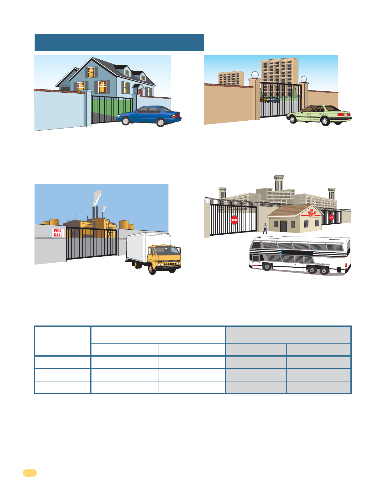
UL325 Entrapment Protection
Class I
A vehicular gate operator (or system) intended for use in a
home of one-to four single family dwelling, or a garage or
parking area associated therewith.
Class II
A vehicular gate operator (or system) intended for use in a
commercial location or building such as a multi-family
housing unit (five or more single family units) hotel,
garages, retail store or other building servicing the general
public.
Class III Class IV
A vehicular gate operator (or system) intended for use in a
industrial location or building such as a factory or loading
dock area or other locations not intended to service the
general public.
A vehicular gate operator (or system) intended for use in a
guarded industrial location or building such as an airport
security area or other restricted access locations not
servicing the general public, in which unauthorized access
is prevented via supervision by security personnel.
STATE PRISON
This table illustrates the entrapment protection requirements for each of the four UL325 classes.
UL325
Classifications
Class I and II
Class III
Class IV
A - Inherent entrapment protection system.
B1 - Provision for connection of, or supplied with, a non-contact sensor (photoelectric sensor or the equivalent).
When used as the PRIMARY device, must be monitored.
B2 - Provision for connection of, or supplied with, a contact sensor (edge device or the equivalent).
When used as the PRIMARY device, must be monitored.
C - Inherent adjustable clutch or pressure relief device.
D - Provision for connection of, or supplied with, an actuating device requiring continuous pressure to maintain
opening or closing motion of the gate.
E - An inherent audio alarm.
6
Horizontal Slide, Vertical Lift, Vertical Pivot Swing and Vertical Barrier (arm)
Primary Protection
A B1, B2 or D A, B1, B2, C or D A or C
A, B1 or B2 A, B1, B2, D or E A, B1, B2, C or D A, B1, B2 or C
A, B1, B2 or D A, B1, B2, D or E A, B1, B2, C, D or E A, B1, B2, C or D
Secondary Protection Primary Protection Secondary Protection
9245-065-C-4-12

Glossary
GATE - A moving barrier such as a swinging, sliding, raising, lowering, or the like, barrier, that is a stand-alone passage
barrier or is that portion of a wall or fence system that controls entrance and/or egress by persons or vehicles and
completes the perimeter of a defined area.
RESIDENTIAL VEHICULAR GATE OPERATOR – CLASS I - A vehicular gate operator (or system) intended for use in a home
of one-to four single family dwelling, or garage or parking area associated therewith.
COMMERCIAL / GENERAL ACCESS VEHICULAR GATE OPERATOR - CLASS II - A vehicular gate operator (or system)
intended for use in a commercial location or building such as a multi-family housing unit (five or more single family units),
hotels, garages, retail store, or other building servicing the general public.
INDUSTRIAL / LIMITED ACCESS VEHICULAR GATE OPERATOR - CLASS III - A vehicular gate operator (or system)
intended for use in an industrial location or building such as a factory or loading dock area or other locations not intended
to service the general public.
RESTRICTED ACCESS VEHICULAR GATE OPERATOR - CLASS IV - A vehicular gate operator (or system) intended for use in
a guarded industrial location or building such as an airport security area or other restricted access locations not servicing
the general public, in which unauthorized access is prevented via supervision by security personnel.
VEHICULAR BARRIER (ARM) OPERATOR (OR SYSTEM) - An operator (or system) that controls a cantilever type device (or
system), consisting of a mechanical arm or barrier that moves in a vertical arc, intended for vehicular traffic flow at
entrances or exits to areas such as parking garages, lots or toll areas.
VEHICULAR HORIZONTAL SLIDE-GATE OPERATOR (OR SYSTEM) - A vehicular gate operator (or system) that controls a
gate which slides in a horizontal direction that is intended for use for vehicular entrance and exit to a drive, parking lot, or
the like.
VEHICULAR SWING-GATE OPERATOR (OR SYSTEM) - A vehicular gate operator (or system) that controls a gate which
moves in an arc in a horizontal plane that is intended for use for vehicular entrance and exit to a drive, parking lot, or the
like.
SYSTEM - In the context of these requirements, a system refers to a group of interacting devices intended to perform a
common function.
WIRED CONTROL - A control implemented in a form of fixed physical interconnections between the control, the associated
devices, and an operator to perform predetermined functions in response to input signals.
WIRELESS CONTROL - A control implemented in means other than fixed physical interconnections (such as radio waves or
infrared beams) between the control, the associated devices, and an operator to perform predetermined functions in
response to input signals.
INHERENT ENTRAPMENT PROTECTION SYSTEM - A system, examples being a motor current or speed sensing system,
which provides protection against entrapment upon sensing an object and is incorporated as a permanent and integral part
of the operator.
EXTERNAL ENTRAPMENT PROTECTION DEVICE - A device, examples being an edge sensor, a photoelectric sensor, or
similar entrapment protection device, which provides protection against entrapment when activated and is not incorporated
as a permanent part of an operator.
ENTRAPMENT - The condition when an object is caught or held in a position that increases the risk of injury.
9245-065-C-4-12
7
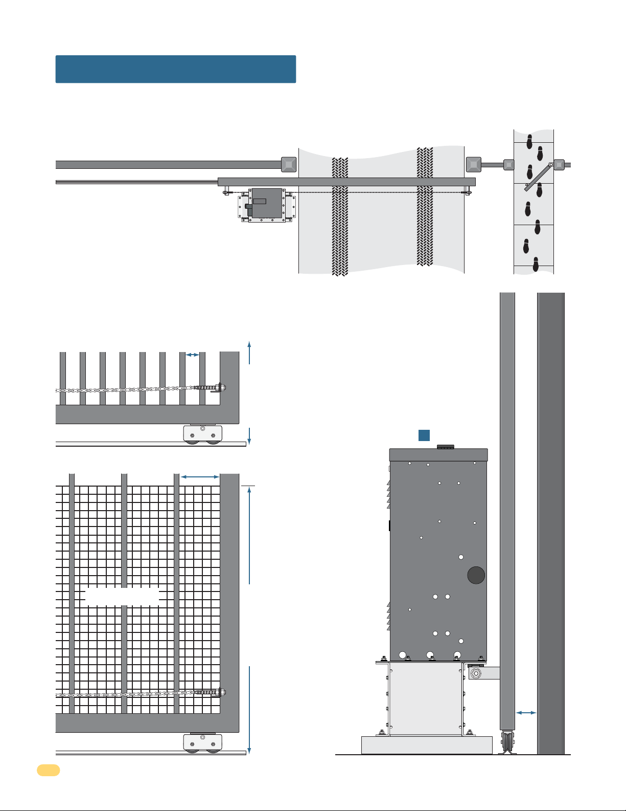
Slide Gate Requirements
The operator is intended for installation only on gates used for vehicles. Pedestrians must be supplied with a separate
access opening. The pedestrian access opening shall be designed to promote pedestrian usage. Locate the gate such that
persons will not come in contact with the vehicular gate during the entire path of travel of the vehicular gate.
(ref. UL 325 56.8.4.b)
Adjacent fence that covers open gate position.
X X X X X X X X X X X X X X X X X X X X X X X X X X X X X X X X X X X X X X X X X X X X X X X X X X X X X X X X X X X X X
High Risk of Entrapment Area
X X X
All openings of a horizontal slide gate are guarded or
screened from the bottom of the gate to a minimum
of six (6) feet (1.83 m) above the ground to prevent
a 2 1/4 inch (57.2 mm) diameter sphere from
passing through the openings anywhere in the gate
and in that portion of the adjacent fence that the
gate covers in the open position.
(ref. ASTM F2200-11a, 6.1.2)
Compliant openings less than 2 1/4”.
Gate Frame and Adjacent Fence Area
Drawings NOT to scale.
Fence
X X XX X XX X XX X XX X XX X XX X X XX X X
X X X X X X X X X X X X X X X X X X X X X X X X X X X X X X X X X X X X X X X X X X X X X X X X X X X X X X X X X X X X X X X X X X X X X
Closed Gate
A gap, measured in the horizontal plane parallel to
the roadway, between a fixed stationary object
nearest the roadway (such as a gate support
post) and the gate frame when the gate is in
either the fully open position or the fully closed
position, shall not exceed 2 1/4 inch (57.2 mm).
(ref. ASTM F2200 6.1.4)
Note: A filler post or barrier may need to be
installed in the gap area to reduce the distance to 2
1/4 inches or less. A contact sensor should be
6 ft. minimum
installed in this area for safety.
(See on next page).
A
Non-compliant openings wider than 2 1/4”.
Less than 2 1/4”
Screened Wire Mesh.
Gate Frame and Adjacent Fence Area
Note: Install
screened wire
mesh to an
existing
non-compliant
gate and the
adjacent fence
that covers
open gate
72” (6 ft) minimum
position
(See above).
Gate Frame
High Risk of Entrapment Area
Gate Support Post
2 1/4” maximum gap area
8
9245-065-C-4-12
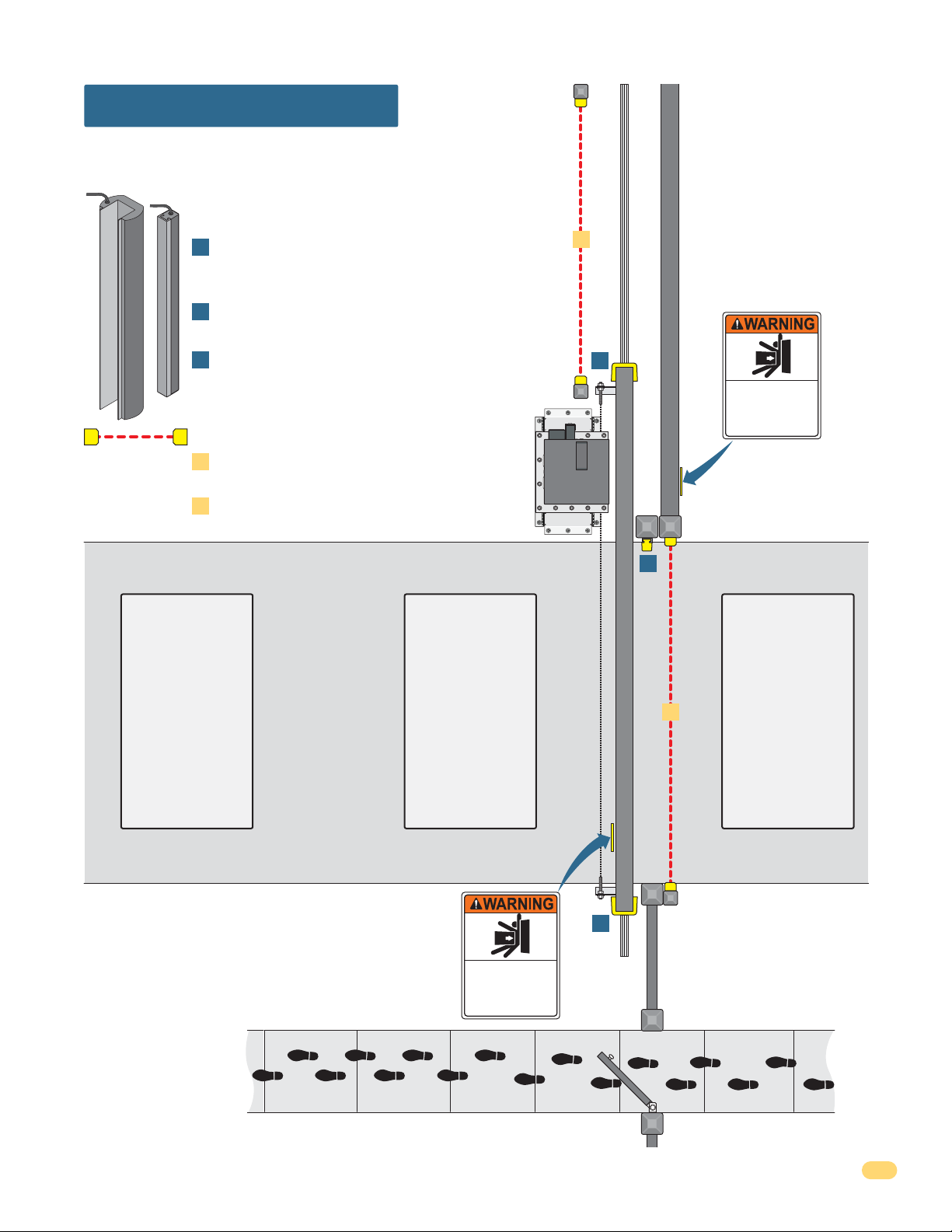
Slide Gate Protection
Entrapment protection devices are required to reduce the risk of injury.
Install sensors where the risk of entrapment or obstruction exists while gate
is moving. Individual requirements will vary.
Contact Sensor (Reversing Edges)
Installed on the fence to help minimize the potential of
A
entrapment between the gate and fence. A filler post or
barrier may need to be installed between fence and gate.
Helps minimize the potential of entrapment during
B
the back travel of the gate.
Minimizes the potential of the gate closing on
C
vehicular or other traffic that loops cannot sense.
Non-Contact Sensors (Photo Sensors)
Minimizes the potential of the gate closing on
1
vehicular or other traffic that loops cannot sense.
Helps minimize the potential of entrapment during
2
the back travel of the gate.
2
Warning Signs
Permanently mounted
Fence
and easily visible from
either side of the gate.
B
Moving Gate Can Cause
Serious Injury or Death
KEEP CLEAR! Gate may move at any time
without prior warning.
Do not let children operate the gate or play
in the gate area.
This entrance is for vehicles only.
Pedestrians must use separate entrance.
Note: DO NOT USE MMTC, Inc. Model IR55 Photo Sensor - P/N 8080-010 for the
9200 series slide gate operator.
Automatic
Exit Loop
(Optional) will
provide an open
command to the
gate operator(s)
when a vehicle
is exiting the
property.
Reverse
Loop
Minimizes the
potential of the
gate closing when
a vehicle is
present. Number
and placement of
loops is dependent
on the application.
Warning Signs
Permanently mounted
and easily visible from
either side of the gate.
Separate
Moving Gate Can Cause
Serious Injury or Death
KEEP CLEAR! Gate may move at any time
without prior warning.
Do not let children operate the gate or play
in the gate area.
This entrance is for vehicles only.
Pedestrians must use separate entrance.
Pedestrian
Walkway
Located so pedestrians
cannot come in contact
with the vehicular gate.
Closed Gate
C
A
Fence
Reverse
Loop
Minimizes the
potential of the
1
gate closing when
a vehicle is
present. Number
and placement of
loops is dependent
on the application.
9245-065-C-4-12
9
SECTION 1 - INSTALLATION
Prior to beginning the installation of the slide gate operator, we suggest that you become familiar with the
instructions, illustrations, and wiring guide-lines in this manual. This will help insure that your installation is
performed in an efficient and professional manner compliant with UL 325 safety and ASTM F2200 construction
standards.
The proper installation of the vehicular slide gate operator is an extremely important and integral part of the
overall access control system. Check all local building ordinances and building codes prior to installing this
operator. Be sure your installation is in compliance with local codes.
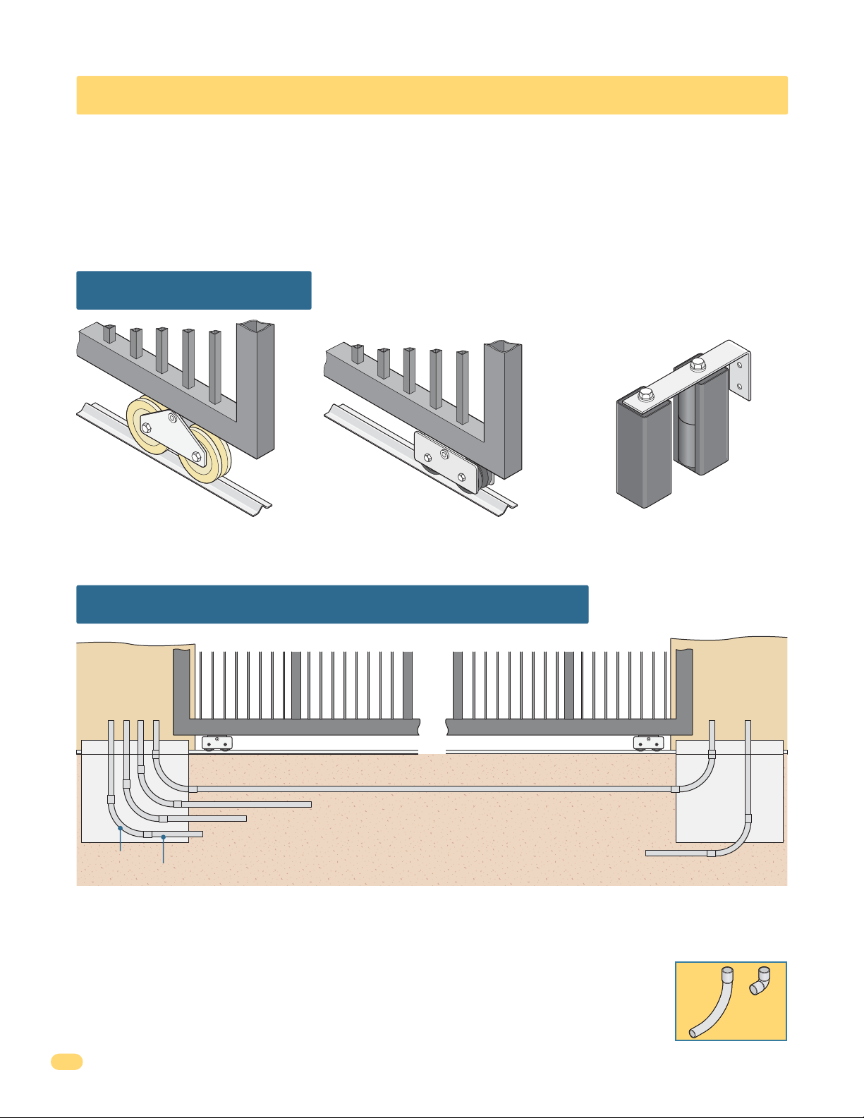
1.1 Gate Hardware
4 Inch6 Inch
DoorKing has a full line of Tandem V-wheels that are ideal for heavy gates and
will ensure safe, reliable and long lasting gate operation. The gate must be
properly installed and roll smoothly in both directions.
Guide Rollers with Protective Covers
Helps to minimize a pinch point on the
gate.
1.2 Underground Conduit Requirements
Single/
Primary
Operator
Position
Primary/Secondary Interconnection Cable (Dual Operator Application Only)
Control and/or P.A.M.S. Wires (Low Voltage wire insulation)
Concrete Pad
Sweeps
3/4 Inch Minimum
• The conduit requirements are for a typical slide gate operator installation (the secondary operator is shown for
those applications where a secondary operator may be used). The conduit requirements for your application may
vary from this depending on your specific needs.
• Use only sweeps for conduit bends. Do not use 90° elbows as this will make wire pulls very difficult
and can cause damage to wire insulation.
• DoorKing recommends using 3/4-inch conduit.
• Be sure that all conduits are installed in accordance with local codes.
• Never run low voltage rated wire insulation in the same conduit as high voltage rated wire insulation.
Loop Lead-In Wires (Low Voltage wire insulation)
AC Input Power (High Voltage wire insulation)
AC Input Power (High Voltage wire insulation)
Secondary
Operator
Position
Sweep
YES
Concrete Pad
Elbow
NO
10
9245-065-C-4-12
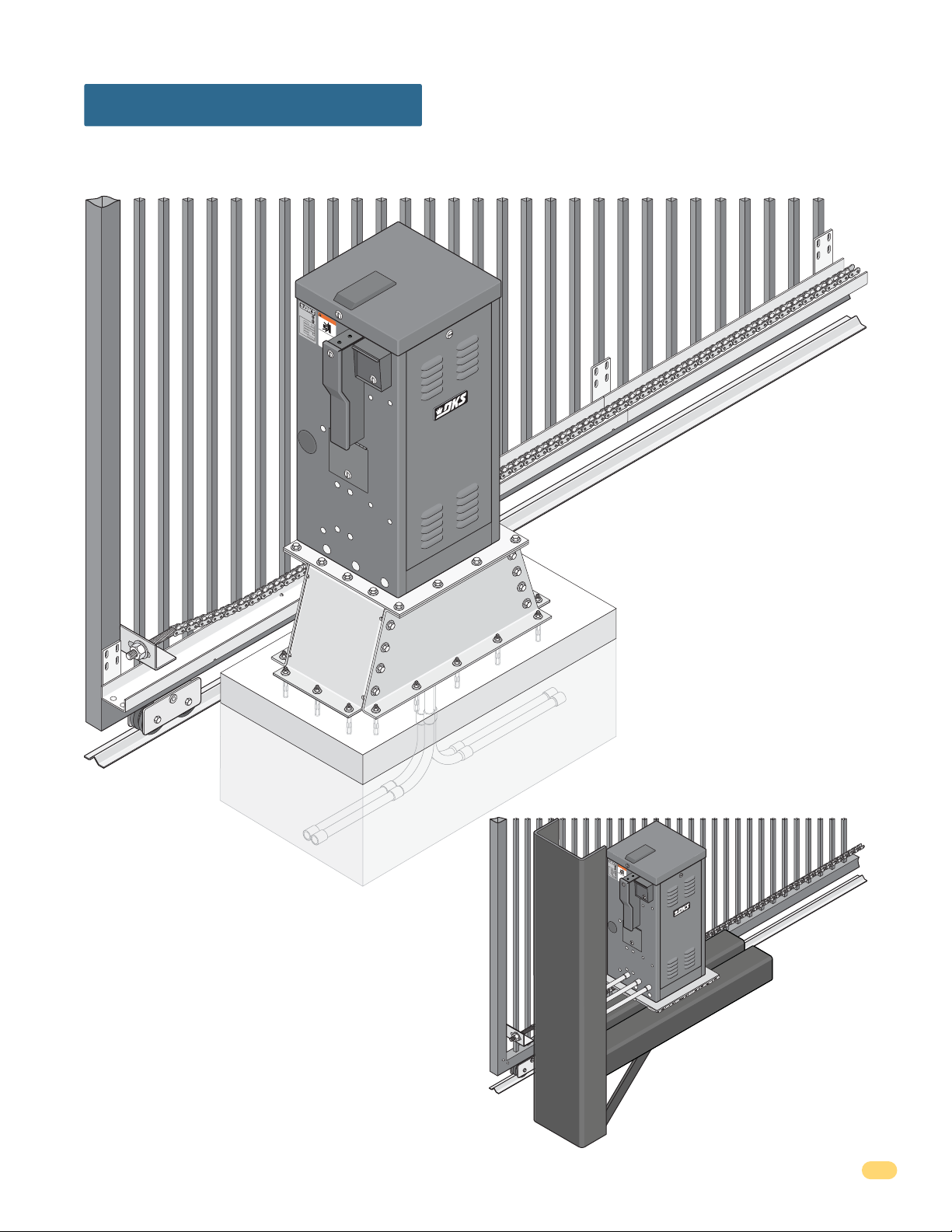
1.3 Installation Options
A chain tray is recommended for gates that are longer than 20 feet in length. The chain tray helps support the weight of the
chain and reduce the chain stretching that occurs over time. DoorKing offers a chain tray kit that will fit any length gate
(P/N 2601-270 10 ft. connecting sections). See page 15 for details.
C
O
N
F
O
A
RM
N
SI
S
/
U
T
L-
O
3
C
C
2
A
ER
5
N/
TI
C
FI
S
A
E
WARNING
D
C
VEH
2
T
2.
O
2
I
N
CU
O
5
.
3
CLA
24
3
LAR
8
2
7
SS
G
AT
E
M
O
OD
PER
E
L
A
T
SER
O
H
R
P
I
A
L
VO
L
TS
AM
P
S
M
M
O
A
PH
X
VI
S
G
A
N
ATE
E
S
G
RIOUS INJ
E
L
G
O
A
A
D
60
T
D
O
o
p
o
E
H
e
rKi
ra
z
C
a
t
n
n
e
A
g
d
g
URY OR
, I
N
f
a
r
t
e
n
e
e
CA
c
o
., I
o
n
f
ly
Do
p
US
n
e
w
g
o
n
h
l
p
o
e
e
o
E
le
t
DE
wo
n
r
a
a
o
g
l
lo
n
p
a
o
d
AT
t
e
d
w
e
r
,
o
a
a
c
b
t
CA
re
h
e
H
s
i
D
t
a
l
g
r
d
a
o
u
i
r
s
t
c
e
e
n
t
n
i
.
i
o
n
o
p
t
t
n
a
o
s
s
t
s
i
h
g
t
p
.
a
h
l
n
w
a
t
y
d
h
in
il
i
n
e
g
g
R
g
a
a
a
ea
t
t
t
e
e
e
d
a
p
is
o
r
a
e
w
t
mo
a
h
n
o
e
v
r’
r
i
n
s
w
g
m
a
.
l
k
a
n
t
h
u
r
a
o
l
u
a
g
n
h
d
s
a
f
e
t
y
i
n
s
t
ru
c
t
i
o
n
s
.
See pages 13, 15 and 16 for details.
Chain Tray
Concrete Pad
Underground
Concrete
Pedestal
Mounting
Stand
R
Underground Conduit
uns
n
Chai
C
O
N
F
O
A
R
N
M
S
I
S
/
U
T
L
O
-
3
C
C
2
A
E
5
N
R
/
T
C
I
F
S
I
A
E
WA
D
C
V
2
T
2
E
O
.
H
2
I
N
C
O
U
53382
.
R
C
L
2
L
A
4
A
7
R
S
N
S
G
A
T
I
E
M
N
O
O
D
P
E
E
G
L
R
A
TO
S
E
H
R
R
P
I
A
L
V
O
L
T
S
A
M
P
S
M
M
O
A
P
X
V
H
G
S
I
A
N
A
E
S
T
G
R
E
E
L
I
GA
O
O
U
A
D
6
D
T
O
S
o
0
p
o
E
H
e
r
I
r
K
N
z
a
C
a
i
t
n
n
e
J
A
g
d
g
U
,
N
f
a
r
I
t
R
e
n
e
e
C
c
o
Y
.
o
n
A
,
f
O
l
D
y
I
p
U
n
o
e
w
g
R
o
S
n
h
l
p
o
e
e
o
E
l
t
D
e
w
n
r
a
a
o
o
g
l
E
l
n
p
o
a
o
d
A
t
e
d
w
e
r
,
o
a
T
a
c
b
t
C
r
h
e
H
s
e
A
i
D
t
l
a
g
r
d
a
o
u
i
r
s
t
c
e
e
n
t
n
i
.
i
o
n
o
p
t
t
n
a
o
s
s
t
s
i
h
g
t
p
.
a
h
l
n
w
a
t
y
d
h
i
i
i
n
l
n
e
g
R
g
g
a
a
a
e
t
t
t
a
e
e
e
d
a
p
i
s
o
r
a
e
w
t
m
a
h
n
o
o
e
v
r
r
i
’
n
s
w
g
m
a
.
l
k
a
n
t
h
u
r
a
o
l
u
a
g
n
h
d
s
a
f
e
t
y
i
n
s
t
r
u
c
t
i
o
n
s
.
it
ray
T
Condu
Specialized Base Plate
See pages 14 and 16 for details.
9245-065-C-4-12
11
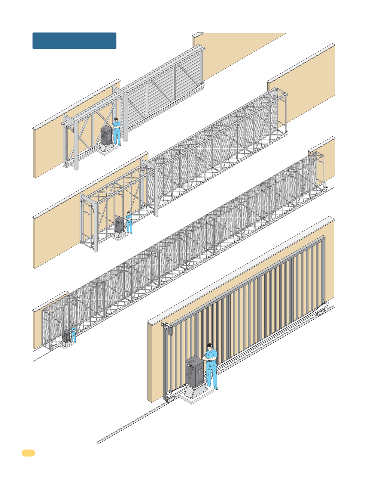
1.3 Gate Types
Heavy-Duty Ornamental Cantilever
CO
N
FO
A
R
N
M
S
I
S
/
U
T
L-
O
CA
C
32
ERTI
N
5
/
C
F
SA
I
W
E
D
C
VE
22.
TO
H
2
A
I
N
C
5
O
U
3
C
.
R
L
3
LAS
2
8
AR
4
2
7
S
N
G
A
T
M
I
E O
O
N
D
EL
PE
G
RA
S
ER
H
T
P
OR
I
A
L
V
O
LTS
A
M
PS
MO
M
A
PH
X
V
S
G
I
A
ER
N
A
SE
T
G
E
I
O
LO
G
U
D
60
A
A
O
o
S
D
T
p
o
H
era
r
E
Kin
I
z
a
N
t
C
n
e
JU
d
g,
A
g
f
a
In
r
N
t
ee
R
e
c
o
on
C
.
Y
,
f
D
A
l
p
I
y
O
n
o
eop
US
w
g
no
R
lewo
h
o
e
t
l
r
e an
al
D
n
E
o
gat
l
E
p
o
o
e
d,
d
w
A
r
e ar
o
at
ch
T
C
b
e g
A
H
s
D
e
i
ld
t
a i
o
r
at
u
r
e
n
s
e.
c
n
o
t
p
i
io
n
t
a
t
st
o
si
n
t
h
p
s.
an
w
g
l
h
ay
d
h
t
i
i
l
i
n
e g
n
g
R
g
ea
a
a
at
t
t
e i
e p
d
e ar
o
s m
a
w
e
t
h
n
a
o
o
er
vi
r
’s
w
n
g
m
a
.
l
a
k
n
t
u
h
a
r
l
o
an
u
g
d
h
sa
f
e
t
y
i
n
s
t
r
u
c
t
i
o
ns.
Heavy-Duty Box Frame Cantilever
C
O
NF
O
A
N
R
S
M
I
S
/
UL
T
C
C
O
-3
A
E
N
R
2
/
5
T
C
I
S
F
A
I
W
ED
C
V
2
T
EH
2
O
.
2
A
I
N
C
5
U
O.
C
3
R
LA
3
L
A
24
8
2
R
S
7
N
S
G
ATE
M
I
O
N
D
O
E
P
L
ER
G
S
ATO
H
E
R
P
I
A
R
L
V
O
L
T
S
A
M
P
S
M
M
O
A
P
X
V
H
S
I
GA
AS
E
N
R
G
E
T
I
E
O
G
L
D
U
6
A
O
O
o
0
S
A
T
p
o
H
D
e
E
r
I
r
K
z
and
N
a
C
i
t
n
J
e
A
g
U
g
f
,
N
r
I
R
a
ee
t
n
Y
e
C
c
D
o
on
A
.,
O
o
f
p
U
I
l
R
no
n
y w
eop
o
S
g
r o
D
E
t
l
al
e
h
E
l
w
p
e an
e
l
A
e
n
o
o
ra
w
T
o
gat
d
H
c
d
t
D
e
,
o
h
g
o
C
e ar
il
b
no
at
A
d
p
s
r
t
e.
a
e
t
e
r
t
a is
u
n
h
s
c
t
t
a
w
t
o
i
n
o
i
h
p
n
d
n
i
R
l
l
s
s
e g
i
ay
n
ea
.
i
g
g
h
a
i
d
n
a
t
t
e i
g
t
o
e
w
at
s m
p
n
e
a
e
t
r
are
h
o
’
o
s
vi
a
m
r
n
w
g
anu
.
al
k
al
t
a
h
r
n
o
d
u
s
g
a
h
f
e
t
y
i
n
s
t
ruct
i
o
ns.
Heavy-Duty Box Frame Roller
C
O
N
F
A
O
N
R
SI
M
C
/
U
S
A
C
T
L
N
E
R
/
O
3
C
TI
25
S
F
A
I
W
E
C
D
V
2
T
2
E
.
H
A
O
2
I
N
C
5
C
U
3
R
O
L
38
L
.
A
A
2
S
2
N
R
4
S
7
G
M
I
A
TE
O
N
D
O
E
G
L
P
S
E
H
E
R
P
R
A
I
T
A
O
L
R
V
O
L
T
S
A
M
P
S
M
M
O
A
P
V
X
S
H
I
E
N
A
G
R
S
G
AT
I
E
O
G
E
D
U
6
A
O
0
o
S
L
T
p
H
o
O
E
I
e
r
a
N
A
r
z
K
C
n
a
D
J
i
A
d
t
n
U
e
N
g
f
R
g
re
C
,
Y
a
I
D
e
A
t
n
e
o
O
o
U
c
R
o
.
f
S
o
n
,
n
p
r
o
E
D
I
l
e
t
y
o
n
E
a
op
p
g
w
A
l
e
l
l
T
l
e
h
o
r
e
D
H
a
w
e
w
a
t
o
n
o
e
c
n
g
o
p
n
g
d
h
d
a
o
a
o
a
i
t
l
,
t
t
t
d
h
e
s
C
b
e
r
w
.
s
a
t
e
A
a
t
r
n
h
r
n
R
e
u
i
a
d
t
e
l
c
o
e
a
i
t
i
p
g
s
n
d
i
on
l
i
a
g
a
o
n
t
a
y
s
w
e
s
t
.
i
i
n
e
i
n
g
s
p
e
h
r
g
m
a
’
t
a
s
t
o
t
h
e
m
v
o
i
a
n
a
r
r
n
g
w
e
u
.
a
a
a
l
l
a
k
n
t
h
d
r
o
s
u
a
g
f
e
h
t
y
i
n
s
t
r
uc
t
i
o
n
s
.
12
Heavy-Duty V-Rail V-Wheel Ornamental
C
O
N
F
O
A
R
N
M
S
I
S
/
U
T
L
O
C
C
3
A
E
2
N
R
5
/
T
C
I
F
S
I
A
W
E
D
C
V
2
T
E
2
O
.
H
2
A
I
N
C
5
O
U
3
C
38
R
.
L
L
2
2
A
A
4
S
R
7
S
NI
G
A
T
M
E
O
N
O
D
E
P
L
E
G
R
S
A
E
H
T
R
P
O
I
A
R
L
V
O
L
T
S
A
M
P
S
M
M
O
A
P
X
V
H
S
G
I
A
E
N
A
S
T
R
E
G
E
I
O
L
G
O
U
D
6
A
A
O
o
0
S
D
T
p
o
H
e
r
E
r
K
I
z
a
a
N
i
t
C
n
n
e
d
J
g
g
A
,
U
f
a
r
N
t
I
e
e
n
R
e
c
o
o
C
.
Y
n
,
f
l
D
A
y
p
I
O
n
o
e
w
U
g
o
n
R
h
l
p
o
S
e
e
o
l
t
e
n
w
r
D
E
a
a
o
g
o
l
l
n
p
E
a
o
o
d
t
e
w
d
e
A
r
o
,
a
a
c
T
b
t
C
re
h
e
s
H
A
i
t
D
a
l
g
r
d
a
o
u
i
r
s
t
c
e
e
n
t
n
i
.
i
o
n
o
p
t
t
n
a
o
s
s
t
s
i
h
g
t
p
.
a
h
l
n
w
a
t
y
d
h
i
i
i
n
l
n
e
g
g
R
g
a
a
a
e
t
t
t
a
e
e
e
d
a
p
i
s
o
r
a
e
w
t
m
a
h
n
o
o
e
v
r
r
i
’
n
s
w
g
m
a
.
l
k
a
n
t
h
u
r
a
o
l
u
a
g
n
h
d
s
a
f
e
t
y
i
n
s
t
r
u
c
t
i
o
n
s
.
• Steel or Aluminum.
• 8,000 lb Max. Weight per Gate.
• Single Operator - 100 Ft Max. Gate Length
Dual Operators - 200 Ft Max. Total Gate Length
• Chain tray recommended for gates over 20 ft. per gate.
9245-065-C-4-12
 Loading...